EP0961221B1 - Probedruckfähiges Aufzeichnungsgerät und -System - Google Patents
Probedruckfähiges Aufzeichnungsgerät und -System Download PDFInfo
- Publication number
- EP0961221B1 EP0961221B1 EP99110185A EP99110185A EP0961221B1 EP 0961221 B1 EP0961221 B1 EP 0961221B1 EP 99110185 A EP99110185 A EP 99110185A EP 99110185 A EP99110185 A EP 99110185A EP 0961221 B1 EP0961221 B1 EP 0961221B1
- Authority
- EP
- European Patent Office
- Prior art keywords
- trial
- user
- button
- data
- Prior art date
- Legal status (The legal status is an assumption and is not a legal conclusion. Google has not performed a legal analysis and makes no representation as to the accuracy of the status listed.)
- Expired - Lifetime
Links
Images


Classifications
-
- G—PHYSICS
- G06—COMPUTING; CALCULATING OR COUNTING
- G06K—GRAPHICAL DATA READING; PRESENTATION OF DATA; RECORD CARRIERS; HANDLING RECORD CARRIERS
- G06K15/00—Arrangements for producing a permanent visual presentation of the output data, e.g. computer output printers
- G06K15/02—Arrangements for producing a permanent visual presentation of the output data, e.g. computer output printers using printers
-
- G—PHYSICS
- G06—COMPUTING; CALCULATING OR COUNTING
- G06K—GRAPHICAL DATA READING; PRESENTATION OF DATA; RECORD CARRIERS; HANDLING RECORD CARRIERS
- G06K2215/00—Arrangements for producing a permanent visual presentation of the output data
- G06K2215/0002—Handling the output data
- G06K2215/0005—Accepting output data; Preparing data for the controlling system
- G06K2215/0011—Accepting output data; Preparing data for the controlling system characterised by a particular command or data flow, e.g. Page Description Language, configuration commands
-
- G—PHYSICS
- G06—COMPUTING; CALCULATING OR COUNTING
- G06K—GRAPHICAL DATA READING; PRESENTATION OF DATA; RECORD CARRIERS; HANDLING RECORD CARRIERS
- G06K2215/00—Arrangements for producing a permanent visual presentation of the output data
- G06K2215/0082—Architecture adapted for a particular function
Definitions
- the present invention relates to an image forming apparatus, such as a shared printer and a digital printing system, which preferably receive data from a plurality of clients through, for example, a local area network (LAN) or the like.
- LAN local area network
- PCs Personal computers
- OA office automation
- PCs personal computers
- a plurality of PCs shares one printer, not each PC having one printer connected to it.
- Each PC may receive data from any other PC in the network and transmit it to the shared printer in the network, whereby the shared printer prints the data.
- Another PC called a "server” is provided in the network to control data that is to be transmitted to the shared printer.
- the server Upon receipt of pieces of print data from a plurality of PCs, the server stores them in a queue. The printer then prints the pieces of data sequentially, i.e. in the order they have been input to the queue. Namely, the printer performs a so-called "first in, first out” process.
- Jpn. Pat. Appln. KOKAI Publication No. 10-11234 discloses the technique of storing data in a queue and processing, thereby to alter the setting of particular print data.
- one printer is connected to two or more PCs by a LAN.
- the printer can therefore receive pieces of print data from the plurality of PCs.
- one printer is shared by a plurality of PC users.
- the printer and the PCs can be arranged more freely than otherwise. For example, each PC user can put the PC on his or her desk, while the shared printer can be installed at any place the PC users have agreed on.
- the user may find that the printed sheets are of lower quality than he or she really wants. For example, the hatching over some printed characters in a word-processed document may happen to be darker or lighter than is desired. In this case, the user needs to print the data again and, hence, must walk back to his or her PC. The user must reset the various print instructions on the PC, then push the print button, and walk again all the way to the shared printer to take the new printed sheets.
- the user may need to spend much time to get desirable printed sheets if his PC is located far from the shared printer and if the sheets printed first by the printer are undesirable ones, compelling him or her to walk back to the PC and reset the print instructions on the PC.
- each PC user needs to walk to the printer to get printed sheets unless the printer is installed just beside his or her PC. Moreover, if the printed sheets are of undesirable quality, the PC user must walk back to his or her PC to reset the print instructions and push the print button, and must walk again to the printer to take the sheet printed for the second time. As a consequence, the PC user cannot get desirable print sheets quickly.
- Document EP-A-0 794 653 discloses an image forming apparatus comprising:
- the object of the present invention is to provide an improved image forming apparatus.
- the image forming apparatus or the printer, prints at least a part of the image data, not all the image data transmitted an image data processing device through the communication line as in the conventional printing system.
- the user examines the printed sheets and, if necessary, changes the print values by operating the control panel provided on the printer. Then, the user operates the control panel to have all image data printed at the printer.
- the present invention provides a printing system that enables the user to get quickly printed sheets of desired quality.
- FIG. 1 shows a printing system according to the invention.
- the system comprises a digital copier (PPC) 1, a plurality of personal computers (PCs) 2 and 3, and a local area network (LAN) 4.
- the PPC 1 is used as a printer in the system.
- the LAN 4 connects PCs 2 and 3 to the PPC 1.
- the PCs 2 and 3 are of the ordinary type. Each can transmit print data to the digital copier 1.
- the digital copier 1 receives the print data from any PC and prints the data.
- the PC 2 has a display section 2a and a keyboard 2b.
- the PC 3 has a display section 3a and a keyboard 3b.
- FIG. 2 is a schematic representation of the digital copier 1, which is the first embodiment of the present invention.
- the digital copier 1 comprises a scanner section 11 and a printer section 12.
- the scanner reads an image signal from an original document, and the image signal is supplied to the printing section 12.
- the printer section 12 prints the image represented by the image signal.
- the scanner section 11 has a CCD sensor (not shown).
- the CCD sensor converts the light reflected from the original document into an electric image signal.
- the printer section 12 is an electrophotographic device. It prints the image represented by the signal, on a sheet of paper.
- the printer section 12 may be replaced with an ink-jet printer.
- the digital copier 1 further comprises a CPU (Central Processing Unit) 13, a ROM 14 (Read Only Memory) 14, a RAM (Random Access Memory) 15, a hard desk drive (HDD) 16, a network interface (I/F) 17, a printer interface (I/F) 18, a scanner interface (I/F) 19, a control panel 20, a control panel interface (I/F) 21, a sorter 22, a sorter control section 23, and a sorter control interface (I/F) 24.
- the CPU 13 controls the other components of the digital copier 1.
- the ROM 14 stores operating software.
- the RAM 15 is provided to store temporarily image data and other data for operating the other components of the copier 1.
- the HDD 16 is used to store various kinds of data.
- the network interface 17 transfers signals between the LAN 4 and the other components of the copier 1.
- the printer interface 18 receives signals from and supplies signals to the printer section 12.
- the scanner interface 19 receives signals from and supplies signals to the scanner section 11.
- the control panel 20 receives various instructions and displays them when operated by a user.
- the control panel interface 21 receives signals from and supplies signals to the control panel 20.
- the sorter 22 sorts printed paper sheets into bins so that the sheets in the same bin may be stapled into a copy of document.
- the sorter control section 23 controls the sorter 22.
- the sorter control interface 24 receives signals from and supplies signals to the sorter control section 23.
- the control panel 20 has a display-input section 20a.
- the display-input section 20a is designed to display and input data, as will be described later in greater detail.
- the digital copier 1 has a bus 25.
- the bus connects the CPU 13 to the ROM 14, RAM 15, HDD 16, network interface 17, printer interface 18, scanner interface 19, control panel interface 21 and sorter control interface 24. Signals are transferred through the bus 25 between the components 13-19, 21 and 24.
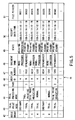
- FIG. 3 illustrates the data, which is transmitted from the PC 2 in the LAN 4 to the digital copier 1 when the PC 2 gives a print request to the digital copier 1.
- This data consists of a user ID field 31, a job number field 32, a document name field 33, a trial print mode field 34, a trial preceding mode field 35, a page field 36, an initial value field 37, and a print data ID field 38.
- the user performs a log-in procedure, inputting the user data into the PC 2 to identify himself or herself.
- the user ID based on the user data is recorded in the user ID field 3.
- the user ID is the code of the person who wishes to have data printed by the digital copier 1.
- the PC 2 may give several print requests to the digital copier 1. In this case, it is necessary to manage the print requests. To this end, serial numbers are assigned to the print requests. Each print request shall be called a "job" hereinafter.
- the serial numbers are recorded in the job number field 32 and will be transmitted from the PC 2 to the digital copier 1.
- the name of the job is recorded.
- the job name is assigned by the software used on the PC 2 to make the print request.
- the job name will be changed to one that depends on the software.
- the fields that characterize the present invention are the trial print mode field 34, the trial preceding mode field 35, and the page field 36.
- the trial print mode field 34 either "normal” or “trial” is recorded. "Normal” indicates that normal printing has been designated. If the job is "normal,” the digital copier 1 will print data in the same way as ordinary printers. If "trial” is recorded in the trial print mode field 34, the printer section 12 will print data for trial. To effect trial printing, the job is set in the print queue 16a provided in the HDD 16, whereby the data is printed for trial.
- trial preceding mode field 35 either "normal” or "pre-printing, trial print indication” is recorded. These values indicate the types of trial print modes.
- page field 36 the page to be printed for trial is recorded if "trial” and "pre-printing, trial print indication" are recorded in the trial print mode field 34 and the trial preceding mode field 35, respectively. In this case, the page is set in the print queue 16a of the HDD 16. If “normal” is recorded in the trial print mode field 34, the values recorded in the trial preceding mode field 35 and page field 36 will be neglected. If “trial” and "normal” are recorded in the trial print mode field 34 and the trial preceding mode field 35, respectively, the value recorded in the page field 36 will be neglected.
- the trial print mode will be described in greater detail.
- This print mode is classified into the following three sub-modes:
- FIG. 5 shows an example of the queue management table 41 stored in the print queue 16a.
- the queue management table 41 may be stored in the RAM 15 if it is small and the RAM 15 has a large storage capacity.
- the queue management table 41 shown in FIG. 5 consists of a queue order field 42, a trial print mode field 43, a trial preceding mode field 44, a page field 45, a user ID field 46, a job number field 47, a document name field 48, a state field 49, a receipt date-time field 50, and a file pointer field 51.
- the data shown in FIG. 3 is stored in the queue management table 41.
- the queue order field 42 the numbers of jobs are stored in the order the jobs are to be executed. Thus, the job of number "1" will be executed first.
- the value recorded in trial print mode field 34 is recorded.
- the value recorded in the trial preceding mode field 44 is recorded.
- the page field 45 the value recorded in the page field 36 (FIG. 3) is recorded.
- the user ID field 46 the value recorded in the page field 36 (FIG. 3) is recorded.
- the job number field 47 the value recorded in the job number field 32 (FIG. 3) is recorded.
- the value recorded in the document name field 33 (FIG. 3) is recorded.
- the state field 49 the value showing the state of the job is recorded. More precisely, either "printing proceeding" or “printing standby" is stored in the state field 49.
- the receipt date-time field 50 the date of receiving the data of the job is stored.
- the file pointer field 51 pointer data for the file, which contains the values recorded in the initial value field 37 and print data ID field 38, respectively, is stored.
- FIG. 6 is a schematic representation of this file 55.
- the file 55 consists of initial value data 56 and print data 57 and is stored in the HDD 16 incorporated in the digital copier 1.
- any specified job recorded in the queue management table 41 can be carried out in the digital copier 1 by operating the control panel 20.
- the HDD 16 stores a password table in which user IDs and passwords for the user IDs are recorded.
- FIG. 7 shows the password table 60.
- the password table 60 is composed of a user ID field 61, a user full-name field 62, and a password field 63.
- the user ID field 61 user IDs are stored.
- the user full-name field 62 the full names of the users assigned with the user IDs are stored.
- the password field 63 the passwords assigned to the users are stored. Since the full names of the users and the like are difficult to input at the control panel 20 of the digital copier 1, the password table 60 is prepared as a file in the PC and transmitted to the digital copier 1 by using file transfer protocol. The password table 60 is thereby stored into the HDD 16 of the digital copier 1.
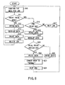
- FIG. 8 is a flow chart explaining the printing routine.
- the job having the smallest serial number is read from the queue order field 42 of the queue management table 41, and the mode for the job, which is recorded in the trial print mode field 43 of the table 41, is confirmed (Step S10).
- the mode recorded in the trial print mode field 43 is the trial print mode (Step S11).
- Step S12 If the mode recorded in the trial print mode field 43 is "normal,” not "trial,” the name of the file, in which the ID and initial value of the print data are recorded, is fetched from the file pointer field 51 (Step S12).
- the print data is developed into image data in the RAM 15 so as to be printed (Step S13).
- the image data is supplied via the printer interface 18 to the printer section 12, which prints the image data on paper sheets (Step S14).
- the file in which the ID and initial value of the print data are recorded is deleted, and the job is deleted from the queue management table 41 (Step S15). Thereafter, the operation returns to Step S10.
- Step S10 the job having the second smallest serial number is read from the queue order field 42, and the mode for this job is confirmed.
- Step S11 If it is determined in Step S11 that the mode recorded in the trial print mode field 43 is "trial,” the trial preceding mode field 44 of the queue management table 41 is checked to see if the mode is "pre-printing” or "trial print indication" (Step S16). If the mode is "normal,” not “pre-printing” or “trial print indication,” the job is skipped (Step S17), and the operation returns to Step S10. In Step S10, the job having the third smallest serial number is read from the queue order field 42, and the mode for the job is confirmed.
- Step S16 If it is determined in Step S16 that the mode is either "pre-printing" or "trial print indication,” the name of the file in which the ID and initial value of the print data are recorded is fetched from the file pointer field 51 (Step S18). The print data is developed into image data in the RAM 15 so as to be printed (Step S19). Next, it is determined whether the value recorded in the trial preceding mode field 44 is "trial" or not (Step S20).
- the image data of the page designated by the value recorded in the page field 45 is supplied via the printer interface 18 to the printer section 12.
- the printer section 12 prints this image data for trial on paper sheets (Step S21). If the value in the trial preceding mode field 44 is "trial,” the image data of the page designated by the value recorded in the page field 45 is developed in the RAM 15, and a mark indicating that the data is printed for trial is added to the image data. The image data containing the mark is supplied via the printer interface 18 to the printer section 12, which prints this image data for trial on paper sheets (Step S22).
- Step S23 the operation goes to Step S23, in which the value in the trial preceding mode field 44, which is "pre-printing" or "trial print indication,” is changed to "normal.”
- the job is skipped (Step S24), and the operation returns to Step S10.
- Step S10 the job having the fourth smallest serial number is read from the queue order field 42, and the mode for the job is confirmed.
- FIG. 9 is a flow chart explaining the trial printing routine.
- the trial printing routine is started when the user walks to the digital copier 1 and operates the display-input section 20a of the control panel 20, thereby selecting the trial print mode.
- Step S30 it is determined whether or not the printer section 12 of the digital copier 1 is printing a job. If the section 12 is printing a job, the print data of the job is saved temporarily so that it may be printed later (Step S31). To be more specific, the various values set, print data and the number of pages already printed are stored, in the form of a file, into the HDD 16 of the digital copier 1.
- Step S32 the user operates the display-input section 20a of the control panel 20, inputting his or her user ID (Step S32).
- the user then operates the display-input section 20a, inputting his or her password (Step S33).
- the user further operates the display-input section 20a, inputting the number of the job he or she wants to print for trial (Step S34).
- the queue management table 41 and the password table 60 are checked to determine whether the user ID and the password, thus input, are correct ones (Step S35). If the user ID or the password, or both are not correct, this fact will be indicated on the display-input section 20a of the control panel 20 (Step S36). Thus ends the trial printing routine.
- Step S35 If it is determined in Step S35 that the user ID and the password are correct, the name of the file, in which the ID and initial value of the print data are recorded, is fetched from the file pointer field 51 (Step S37). The print data is developed into image data in the RAM 15 so as to be printed (Step S38).
- Step S39 the user operates the display-input section 20a, setting various print values (Step S39).
- These print values are print density, sorting mode, stable mode, stapling position, double-side print, number of copies, and the like.
- additional print values such as color saturation, color balance, and the like, must be input.
- the page of data to be printed for trial can be designated.
- Step S40 it is determined whether or not the trial printing has been designated, or whether a trial printing button displayed on the display-input section 20a has been selected. If YES, that is, if the trial print button has been selected, the image data of the pages, which are designated by the values set in Step S39 and which are to be printed, is supplied through the printer interface 18 to the printer section 12. The printer section 12 prints only the designated page of image data for trial on paper sheets (Step S41). Then, the operation returns to Step S39. After examining the quality of the image printed for trial, the user can set, if necessary, different print values to have the same image data printed in more desirable quality.
- Step S40 that is, if the print button displayed on the display-input section 20a has been selected, all pages of image data are supplied via the printer interface 18 to the printer section 12.
- the printer section 12 prints all pages of image data on paper sheets in accordance of the print values set in Step S39 (Step S42).
- Step S43 the file in which the ID and initial value of the print data are recorded is deleted, and the job is deleted from the queue management table 41 (Step S43). It is then determined whether data has been saved in Step S31 in any file (Step S44). If there is data saved, the data is fetched from the file, and the job interrupted at the start of the trial printing routine is resumed (Step S45). Thus, the trial printing routine does end.
- the job-deleting routine will be described, with reference to the flow chart of FIG. 10. This routine is initiated when the user comes to the digital copier 1 and operates the display-input section 20a of the control panel 20, thereby selecting the job-deleting mode.
- Step S51 the user operates the display-input section 20a, inputting his or her user ID (Step S51).
- the user then operates the display-input section 20a, thereby inputting his or her password (Step S52). It is then determined whether the user ID and the password are correct or not (Step S53). If the user ID and the password are not correct, this fact is displayed on the display-input section 20a of the control panel 20 (Step S54).
- the job-deleting routine ends.
- Step S55 If it is determined in Step S53 that the user ID and the password are correct, all data of the job is read from the queue management table 41 (Step S55).
- the job data is displayed in the form of a table on the display-input section 20a of the control panel 20 (Step S56). Seeing the job data displayed, the user operates the display-input section 20a designating the job to be deleted (Step S57). Then, the file containing the initial value and print data of the job and the job itself are deleted from the queue management table 41 (Step S58). Thus ends the job-deleting routine.
- FIG. 11 shows a window 101 which is displayed on the display section 2a of the PC 2, which is used to set the trial print mode on the PC 2.
- This window 101 is displayed to set print values for the digital copier 1, while the PC 2 is using software. Hence, the window 101 is displayed by the use of the driver software installed in the PC 2 for driving the digital copier 1.
- Shown in the window 101 are a trial print tab 102, a density-adjusting tab 103, and a sheet-selecting tab 104.
- the trial print tab 102 is used to designate trial printing.
- the density-adjusting tab 103 is used to adjust the print density.
- the sheet-selecting tab 104 is used to select sheets of a desired size. One of these tabs 102, 103 and 104 is selected by moving a pointer 105 to the tab and clicking a mouse (not shown).
- check buttons 106 to 109, page input area 110, all-page area 111, job number area 112, OK button 113, and cancel button 114 will be displayed in the window 110.
- the check button 106 is selected to designate trial printing, a check button 107 to designate the normal mode of trial printing, a check button 108 to designate the pre-print mode of trial printing, and a check button 109 to designate pre-print display mode of trial printing.
- the page of data to be printed for trial is displayed in the page input area 110.
- the number of all pages to be printed is displayed in all-page area 111.
- the number of the job is displayed in the job number area 112.
- the user moves the pointer 105 to the check button 106 and clicks the mouse, thus setting the digital copier 1 in the trial print mode. Unless or until the check button 106 is thus activated, the other check buttons 107, 108 and 109 and the areas 110 and 112 remain invalid.
- the check button 108 is activated, the trial printing precedes to the normal printing.
- the area 110 can be selected and the check button 109 can be activated.
- the check button 108 remains active, the user may operate the keyboard 3a of the PC 2, inputting the page he or she wishes to have printed for trial and displaying the page in the area 110. If so, the number of all pages of the document is displayed in the area 111. Any one of the pages displayed in the area 111 can be designated and printed for trial.
- the check button 109 can be activated to designate the printing of a mark indicating that the data is printed for trial, as illustrated in FIG. 4, along with the image data printed in the pre-print display mode of trial printing. Unless the check button 108 is activated, the mark cannot be printed.
- the digital copier 1 Every time the digital copier 1 receives a print job, it issues a serial number for the job to the PC 2. This serial number is displayed in the job number area 112. The serial number is a decimal four-digit number, which is easy to learn. When the digital copier 1 receives a print job after the serial number has reached "9999,” the serial number will change to "0001.”
- the OK button 113 is selected by clicking the mouse while the pointer 105 is pointing to this button 113, after all values have been set for trial printing as described above.
- the cancel button 114 is selected by clicking the mouse while the pointer 105 is pointing the button 114, thereby to cancel all values that have been set for trial printing.
- FIG. 12 depicts the initial menu displayed on the display-input section 20a. That is, a PPC-setting button 201, a trial printing button 202, and a job-deleting button 203 are displayed on the display-input section 20a when the power switch of the digital copier 1 is turned on.
- the PPC-setting button 201 is touched to use the copier 1 as an ordinary one and set various print instructions. The print instructions are set in the known manner and will not be described.
- the job-deleting button 203 is touched to delete the job from the queue management table 41.
- the trial printing button 202 will be described. After designating the trial printing by selecting the buttons displayed on the display section 2a and by operating the key board 2b, the user comes to the digital copier 1. The user touches the trial printing button 202 displayed on the display-input section 20a. As a result, the display-input section 20a displays the menu shown in FIG. 13.
- this menu consists of a user ID area 231, a password area 232, a job number area 233, a character key pad 234, a reset button 235, and an input button 236.
- the user inputs his or her user ID in the area 231, by touching the selected keys of the character keypad 234. If the user inputs a wrong user ID, he or she touches the reset button 235, thereby clearing the wrong user ID. After inputting the user ID in the area 231, the user touches the input button 236. Then, the user touches the selected keys of the character key pad 234, thereby inputting his or her password. The password is not displayed in the password area 232. Rather, a prescribed number of asterisks (*) or underline bars (_) is displayed in the password area 232. After inputting the password, the user touches the input button 236. Then, the user touches the selected keys of the character key pad 234, inputting the job number in the job number area 233. Finally, the user touches the input button 236. If the user has input a wrong job number, an error message will be displayed, and he or she can perform no further operations.
- the menu will change to the new one shown in FIG. 14.
- the new menu consists of a density tab 241, a sort tab 242, a double-side print tab 243, and a copy number tab 244. While each of these tabs remains selected, the value for the tab can be set.
- FIG. 14 shows the case where the density tab 241 is selected.
- a photograph mode button 245, a density scale 246, a density-increasing button 247, a density-decreasing button 248, a ten-key pad 249, a reset button 250, a trial print page area 251, a total page number area 252, a trial print button 253, and a print button 254 are displayed in the menu.
- the user may touch the photograph mode button 245 to print a document in photograph mode.
- the button 245 is displayed in reverse mode as long as it remains active.
- a mark 255 indicates the density selected at present.
- the user may touch the density-increasing button 247 to shift the mark 255 toward the upper limit, thereby to increase the print density.
- the user may touch the density-decreasing button 248 to shift the mark 255 toward the lower limit, thereby to decrease the print density.
- the ten-key pad 249 is provided for inputting a page number in the trial print page area 251 that is displayed below the ten-key pad 249.
- the number displayed in the trial print page area 251 is cleared when the reset key 250 is touched.
- the total page number area 252 the total page number of the document is displayed.
- the trial print button 253 is touched to print the page of the document, which is displayed in the trial print page area 251.
- the menu as shown in FIG. 14 does not change at all.
- the display-input section 20a will display the menu shown in FIG. 15.
- This menu has a staple button 260, a sort button 261, a group button 262, an upper staple position button 263, a middle staple position button 264, a lower staple position button 265, a staple position area 266, a ten-key pad 249, a reset button 250, a trial print page area 251, a total page number area 252, a trial print button 253, and a print button 254.
- the user may touch the staple button 260 to staple the printed sheets as a copy of the document. While the button 260 remains active, it is displayed in reverse mode, enabling the user to activate the upper staple position button 263, middle staple position button 264 and lower staple position button 265. If the upper staple position button 263 is activated, the copied sheets will be stapled at the upper margin. If the middle staple position button 264 is activated, the copied sheets will be stapled at the middle margin. If the lower staple position button 265 is activated, the copied sheets will be stapled at the lower margin. Only one staple position button can be activated at a time. The staple position selected is schematically indicated in the staple position area 266.
- the user may touch the sort button 261 to sort copied paper sheets into bins.
- the group button 262 is touched to sort copied sheets, thereby to make groups.
- the sort button 261 and the group button 262 cannot be selected at the same time.
- the ten-key pad 249, reset button 250, trial print page area 251, total page number area 252, trial print button 253 and print button 254 are identical in function to those displayed in the menu of FIG. 14.
- the display-input section 20a will display the menu shown in FIG. 16.
- the menu has a double-side print button 268, a single-side print button 269, a ten-key pad 249, a reset button 250, a trial print page area 251, a total page number area 252, a trial print button 253, and a print button 254.
- the user may touch the double-side print button 268 to print any two consecutive pages of data on the two sides of a paper sheet, respectively.
- the user may touch the single-side print button 269 to print each page of data on one side of a paper sheet.
- the ten-key pad 249, reset button 250, trial print page area 251, total page number area 252, trial print button 253 and print button 254 are identical in function to those displayed in the menu of FIG. 14.
- the display-input section 20a will display the menu shown in FIG. 17.
- This menu has a copy number area 270, a copy number button 271, a trial print page button 272, a ten-key pad 249, a reset button 250, a trial print page area 251, a total page number area 252, a trial print button 253, and a print button 254.
- the user can set a desired number of copies.
- the copy number setting button 271 Once the copy number setting button 271 has been activated, the user can operate the ten-key pad 249 and can activate the reset button 250 to set any desired number of trial copies.
- the desired number of trial copies, set by operating the ten-key pad 249, is displayed in the copy number area 270.
- the user touches the trial print page button 272, whereby he or she can operate the ten-key pad 249 and activate the reset button 250 to designate the page that should be printed for trial.
- the ten-key pad 249, reset button 250, trial print page area 251, total page number area 252, trial print button 253 and print button 254 function in the same way as those displayed in the menu of FIG. 14.
- the menu shown in FIG. 18 is displayed on the display-input section 20a.
- the menu has a sort tab 242, a double-side print tab 243, a copy number tab 244, a density-saturation tab 280, and a color balance tab 281.
- the menu shown in FIG. 18 is displayed while the density-saturation tab 280 remains selected.
- the menu further has a density scale 246, a density-increasing button 247, a density-decreasing button 248, a color saturation scale 282, a saturation-increasing button 283, a saturation-decreasing button 284, a ten-key pad 249, a reset button 250, a trial print page area 251, a total page number area 252, a trial print button 253, and a print button 254.
- the color saturation scale 282 has a mark 285 that indicates the color saturation set at present.
- the user may touch the saturation-increasing button 283 to shift the mark 285 toward the upper limit, thereby to increase the color saturation.
- the user may touch the saturation-decreasing button 284 to shift the mark 285 toward the lower limit, thereby to decrease the color saturation.
- the menu of FIG. 19 has a cyan density scale 290, a cyan-density increasing button 291, a cyan-density decreasing button 292, a magenta density scale 294, a magenta-density increasing button 295, a magenta-density decreasing button 296, a yellow density scale 298, a yellow-density increasing scale 299, a yellow-density decreasing scale 300, a black density scale 302, a black-density increasing button 303, and a black-density decreasing button 304.
- the menu further has a ten-key pad 249, a reset button 250, a trial print page area 251, a total page number area 252, a trial print button 253, and a print button 254.
- the user touches the cyan-density increasing button 291 or the cyan-density decreasing button 292, whereby a mark 293 moves on the cyan density scale 290.
- the user touches the magenta-density increasing button 295 or the magenta-density decreasing button 296 to adjust the magenta density, whereby a mark 297 moves on the magenta density scale 294.
- the user touches the yellow-density increasing button 299 or the magenta-density decreasing button 300 to adjust the magenta density, whereby a mark 301 moves on the yellow density scale 298.
- the user touches the yellow-density increasing button 299 or the magenta-density decreasing button 300 to adjust the magenta density, whereby a mark 301 moves on the yellow density scale 298.
- While the display-input section 20a is displaying the initial menu shown in FIG. 12, the user may touch the job-deleting button 203 in order to delete the job from the queue management table 41.
- the display-input section 20a displays the menu shown in FIG. 20, instead of the initial menu (FIG. 12).
- the menu of FIG. 20 has a user ID area 321, a password area 322, a character keypad 323, a reset button 324, and an input button 325.
- the user inputs his or her user ID in the area 321, by touching the selected keys of the character keypad 323. If the user inputs a wrong user ID, he or she touches the reset button 324, thereby clearing the wrong user ID. After inputting the user ID in the area 321, the user touches the input button 325. The user then touches the selected keys of the character keypad 323, thereby inputting his or her password. The password is not displayed in the password area 322. Rather, a prescribed number of asterisks (*) or underline bars (__) is displayed in the password area 322. After inputting password, the user touches the input button 325. If a wrong password has been input, the display-input section 20a will display an error message. In this case, the user cannot use the digital copier 1.
- the display-input section 20a will display a job deletion menu.
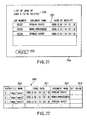
- the section 20a displays the job deletion menu for user B, which is shown in FIG. 21.
- the menu has a user name area 330, a job list area 331, and a deletion button 332.
- the jobs, which user B has performed and which are recorded in the queue management table 41, are displayed in the job list area 331. Seeing these jobs displayed in the area 331, User B touches any job he or she wishes to delete. Then, the job thus selected is displayed in reverse mode. When user B touches the deletion button 332, the job selected is deleted.
- the print values which have been set in any personal computer (PC 2, PC 3) shown in FIG. 1 to make a print request to the digital copier 1, are stored in the personal computer. If the print values are changed in the digital copier 1 to new values, the new print values are transmitted to the personal computer. Hence, the same file can be printed again in the new print values, even if some of the print values, such as print density, are altered to print the file for trial.
- the print driver provided in the personal computer (PC 2, PC 3) that makes a print request has the driver management table 340 shown in FIG. 22 to store the print values.
- the driver management table 340 is recorded on a hard disk (not shown) provided in the personal computer (PC 2, PC 3).
- the driver management table 340 provided in, for example, PC 2 will be described.
- the driver management table 340 consists of a path/file name field 350, an issue date field 351, a document name field 352, and a set value field 353.
- the paths and file names on the PC 2 are recorded in the path/file name field 350, so that the files containing the documents, for which a print request has been made, may be identified.
- the date of making the print request is recorded in the issue date field 351.
- the name of the document is recorded in the document name field 352.
- the print values set, such as the density are recorded in the set value field 353.
- the print driver provided in the PC 2 holds the data set when the print request is made in the PC 2.
- FIG. 23 illustrates the queue management table 400 provided in the digital copier 1.
- the table 400 consists of a queue order field 354, a trial print mode field 355, a trial preceding mode field 356, a page field 357, a user ID field 358, a job number field 359, a document name field 360, a state field 361, a receipt date-time field 362, a PC address field 363, and a file pointer field 364.
- the queue management table 400 is recorded, for example, on the hard disk provided in the digital copier 1.
- This table 400 differs from the queue management table 41 used in the first embodiment, only in that it has an additional field, i.e., the PC address field 363. Therefore, the other fields of the table 400 will not be described.
- the PC address field 363 shows the address of the PC that has sent a print job to the digital copier 1.
- the header of any data packet transmitted via the LAN 4 usually contains the source address and the destination address.
- the address of the PC is acquired from the header of the data packet and is recorded in the PC address field 363.
- Step S39 (FIG. 9) the various print values are changed. More precisely, the address of the PC which has sent the job is read from the queue management table 400 after all pages of the image data are printed in Step S42.
- the digital copier 1 transmits the data representing the print values to the PC having this address.
- the print driver provided in the PC writes the data in the set value field 353 of the driver management table 340, deleting the data that has recorded therein before.
- the print values set for the file and changed in the PC to achieve trial printing in the digital copier 1 can thereby be restored to ones initially set in the copier 1 for the file. Hence, the file can be printed again in the print values set in the digital copier 1.
- the embodiments of the present invention enable the user of a personal computer connected to a LAN to reset print instructions easily at the printer or digital copier connected to the LAN, thereby to get printed sheets of the quality he or she desires.
- the present invention can provide a printing apparatus and a printing system, which comprises at least one printer and a plurality of personal computers and which enables each user to reset print instructions at the printer to get printed sheets of the quality he or she desires.
Claims (5)
- Bildbildungsvorrichtung (1) enthaltend
ein Empfangsmittel (17) zum Empfangen einer Mehrzahl von Seiten von Bilddaten, die über eine Übertragungsleitung gesendet werden, und zum Empfangen eines Teildruck-Anforderungssignals, das das Drucken nur eines Teils der Bilddaten anfordert; und
ein Speichermittel (16), 16a, 41) zum Speichern der Bilddaten und des Teildruck-Anforderungssignals, die beide an dem Empfangsmittel empfangen werden;
ein erstes Druckmittel (12) zum Probedrucken eines Teils der Bilddaten und eines Bilds (7), das angibt, dass die probegedruckten Daten Teil der Bilddaten sind, auf ein Papierblatt (6) in Antwort auf das Teildruck-Anforderungssignal, das in dem Speichermittel (16, 16a, 41) gespeichert ist; und
ein zweites Druckmittel (12) zum Drucken aller Seiten der Bilddaten, die in dem Speichermittel gespeichert sind, bei Empfang einer Druckanweisung für alle Seiten von einem Benutzer über eine Steuerfeld (20), das auf der Bildbildungsvorrichtung bereitgestellt ist, nachdem das erste Druckmittel den Teil der Bilddaten gedruckt hat, wobei die Druckanweisung für alle Seiten verlangt, dass die Bilddaten in einer bestimmten Art und Weise gedruckt werden. - Bildbildungsvorrichtung (1) nach Anspruch 1, wobei die Bildbildungsvorrichtung (1) ausgelegt ist zum Empfangen des Teildruck-Anforderungssignals von einem PC (2), der ein Fenster (101) aufweist, das ein Optionsschaltfeld (109) bereitstellt zum Bestimmen des Vordruckanzeigemodus des Probedrucks.
- Bildbildungsvorrichtung (1) nach Anspruch 1 oder 2, ferner mit
einem Transfermittel (17) zum Übertragen der Daten, die die bestimmte Art und Weise darstellen, an eine Datenverarbeitungsvorrichtung, die die Bilddaten an die Bildbildungsvorrichtung über die Übertragungsleitung gesendet hat, nachdem das zweite Druckmittel (12) alle Seiten von Bilddaten gedruckt hat. - Bildbildungsvorrichtung (1) nach einem der vorangegangenen Ansprüche, wobei
das erste Druckmittel (12) ausgelegt ist zum Drucken, in Farbe, des Teils der Bilddaten, die in dem Speichermittel (16, 16a, 41) gespeichert sind; und
das zweite Druckmittel (12) ausgelegt ist zum Drucken, in Farbe, aller Seiten der Bilddaten, die in dem Speichermittel gespeichert sind, bei Empfang einer Farbdruckanweisung für alle Seiten von dem Benutzer über das Steuerfeld (20), das auf der Bildbildungsvorrichtung bereitgestellt ist, nachdem das erste Druckmittel den Teil der Bilddaten in Farbe gedruckt hat. - Bildbildungsvorrichtung (1) nach Anspruch 4, wobei
das erste Druckmittel (12) ausgelegt ist zum Drucken des Teils der Bilddaten in Farbe in Antwort auf das Teildruck-Anforderungssignal, das in dem Speichermittel (16, 16a, 41) gespeichert ist, bei Empfang einer Teilfarbdruckanweisung von dem Benutzer über das Steuerfeld (20), das auf der Bildbildungsvorrichtung bereitgestellt ist.
Applications Claiming Priority (2)
| Application Number | Priority Date | Filing Date | Title |
|---|---|---|---|
| JP10150345A JPH11342658A (ja) | 1998-05-29 | 1998-05-29 | 印刷装置と印刷システム |
| JP15034598 | 1998-05-29 |
Publications (3)
| Publication Number | Publication Date |
|---|---|
| EP0961221A2 EP0961221A2 (de) | 1999-12-01 |
| EP0961221A3 EP0961221A3 (de) | 2001-01-10 |
| EP0961221B1 true EP0961221B1 (de) | 2006-10-11 |
Family
ID=15494971
Family Applications (1)
| Application Number | Title | Priority Date | Filing Date |
|---|---|---|---|
| EP99110185A Expired - Lifetime EP0961221B1 (de) | 1998-05-29 | 1999-05-26 | Probedruckfähiges Aufzeichnungsgerät und -System |
Country Status (4)
| Country | Link |
|---|---|
| US (2) | US6724492B1 (de) |
| EP (1) | EP0961221B1 (de) |
| JP (1) | JPH11342658A (de) |
| DE (1) | DE69933505T2 (de) |
Families Citing this family (30)
| Publication number | Priority date | Publication date | Assignee | Title |
|---|---|---|---|---|
| JPH11342658A (ja) * | 1998-05-29 | 1999-12-14 | Toshiba Corp | 印刷装置と印刷システム |
| US6496278B1 (en) * | 1998-12-02 | 2002-12-17 | Ricoh Company, Ltd. | Image forming apparatus and printer apparatus |
| JP2001130068A (ja) * | 1999-11-08 | 2001-05-15 | Canon Inc | 画像形成システム及び画像形成方法、記憶媒体 |
| JP2001159963A (ja) * | 1999-12-01 | 2001-06-12 | Minolta Co Ltd | プリント装置、プリントシステムおよびプリント方法 |
| JP3941345B2 (ja) * | 2000-06-05 | 2007-07-04 | 富士ゼロックス株式会社 | 印刷システムおよびその印刷制御方法 |
| US7386790B2 (en) * | 2000-09-12 | 2008-06-10 | Canon Kabushiki Kaisha | Image processing apparatus, server apparatus, image processing method and memory medium |
| US6888647B2 (en) * | 2001-02-06 | 2005-05-03 | Eastman Kodak Company | Proofing with watermark information created by a raster imaging processor |
| JP2004032704A (ja) * | 2002-05-09 | 2004-01-29 | Canon Inc | 画像形成装置、その制御方法、プログラム、記憶媒体、印刷システムに好適な方法および印刷システム |
| JP4364484B2 (ja) | 2002-06-24 | 2009-11-18 | 東芝テック株式会社 | 画像形成装置、および画像形成方法 |
| US7710596B2 (en) * | 2002-08-29 | 2010-05-04 | Canon Kabushiki Kaisha | Image processing apparatus, image processing apparatus administration information display method, system, program and storage medium |
| JP2004126871A (ja) * | 2002-10-01 | 2004-04-22 | Canon Inc | 印刷制御方法および装置 |
| JP2004341588A (ja) * | 2003-05-13 | 2004-12-02 | Dainippon Screen Mfg Co Ltd | ネットワークを利用した画像の出力演算サービス |
| JP3840244B2 (ja) * | 2003-11-12 | 2006-11-01 | キヤノン株式会社 | 印刷装置、ジョブ処理方法、記憶媒体、プログラム |
| JP5049458B2 (ja) * | 2004-09-03 | 2012-10-17 | キヤノン株式会社 | 画像形成装置、ジョブ処理方法、記憶媒体、及び、コンピュータプログラム |
| JP4996050B2 (ja) * | 2004-10-29 | 2012-08-08 | キヤノン株式会社 | 印刷装置、及びその制御方法 |
| JP4761535B2 (ja) * | 2005-02-23 | 2011-08-31 | キヤノン株式会社 | 文書管理装置及び方法、プログラム |
| JP4577058B2 (ja) * | 2005-03-23 | 2010-11-10 | 富士ゼロックス株式会社 | 印刷制御装置および方法およびプログラム |
| JP2008072427A (ja) * | 2006-09-14 | 2008-03-27 | Konica Minolta Business Technologies Inc | 画像形成装置及びクライアント/サーバ型情報処理システム並びに情報処理方法 |
| JP4763640B2 (ja) * | 2007-03-27 | 2011-08-31 | ブラザー工業株式会社 | 印刷装置、制御プログラム及び印刷システム |
| JP2009012294A (ja) * | 2007-07-04 | 2009-01-22 | Fuji Xerox Co Ltd | 印刷システム、プリンタ装置及びプログラム |
| JP2009028984A (ja) * | 2007-07-26 | 2009-02-12 | Brother Ind Ltd | 画像形成装置 |
| JP2010052384A (ja) * | 2008-08-29 | 2010-03-11 | Ricoh Co Ltd | 画像形成装置、印刷制御方法、及びプログラム |
| JP5234016B2 (ja) * | 2009-02-25 | 2013-07-10 | 株式会社リコー | 画像形成装置及び画像形成方法 |
| JP4894875B2 (ja) * | 2009-03-18 | 2012-03-14 | コニカミノルタビジネステクノロジーズ株式会社 | 情報処理装置、情報処理装置の制御方法、および情報処理装置の制御プログラム |
| JP4920733B2 (ja) * | 2009-09-30 | 2012-04-18 | シャープ株式会社 | 印刷制御プログラム、印刷制御方法、プリンタ、及び印刷システム |
| JP5434659B2 (ja) * | 2010-02-19 | 2014-03-05 | 富士ゼロックス株式会社 | ページ割付制御装置、画像処理装置、ページ割付制御プログラム |
| JP5081939B2 (ja) * | 2010-03-23 | 2012-11-28 | シャープ株式会社 | 操作機器、その操作機器を備えた電子機器および画像処理装置、ならびにその操作機器における情報表示方法 |
| JP5895652B2 (ja) * | 2012-03-29 | 2016-03-30 | ブラザー工業株式会社 | プリンタ |
| JP5546584B2 (ja) * | 2012-06-22 | 2014-07-09 | キヤノン株式会社 | 画像形成装置、印刷処理方法、記憶媒体、及び、コンピュータプログラム |
| JP6988311B2 (ja) * | 2017-09-22 | 2022-01-05 | 富士フイルムビジネスイノベーション株式会社 | 情報処理装置、記録装置、情報処理システム、及びプログラム |
Family Cites Families (28)
| Publication number | Priority date | Publication date | Assignee | Title |
|---|---|---|---|---|
| JPS57153332A (en) * | 1981-03-19 | 1982-09-21 | Mitsubishi Electric Corp | Printer |
| US4821107A (en) * | 1987-01-26 | 1989-04-11 | Minolta Camera Kabushiki Kaisha | Multi-functional imaging apparatus |
| JPH03196266A (ja) * | 1989-12-25 | 1991-08-27 | Toshiba Corp | 画像形成記憶装置 |
| US5202828A (en) * | 1991-05-15 | 1993-04-13 | Apple Computer, Inc. | User interface system having programmable user interface elements |
| JP3500164B2 (ja) * | 1992-05-19 | 2004-02-23 | 理想科学工業株式会社 | 孔版印刷装置 |
| US5321427A (en) * | 1992-06-03 | 1994-06-14 | Eastman Kodak Company | Print head modulator |
| JPH0695463A (ja) * | 1992-09-09 | 1994-04-08 | Ricoh Co Ltd | 画像形成装置 |
| DE4491655T1 (de) * | 1993-03-17 | 1995-04-27 | Ricoh Kk | Bildaufzeichnungseinrichtung |
| JP2960630B2 (ja) * | 1993-07-30 | 1999-10-12 | キヤノン株式会社 | 印刷制御装置および印刷制御方法 |
| JP3271862B2 (ja) * | 1994-03-10 | 2002-04-08 | 株式会社リコー | ページプリンタ |
| US5521710A (en) * | 1994-04-12 | 1996-05-28 | Xerox Corporation | Method of applying electronically stored labels from a source job to a destination job in a printing system |
| US5555099A (en) * | 1994-12-09 | 1996-09-10 | Eastman Kodak Company | Reproduction apparatus and method with proof set page numbering |
| JP3539781B2 (ja) | 1995-02-14 | 2004-07-07 | 東芝テック株式会社 | 複合型画像形成装置 |
| US5984446A (en) * | 1995-04-12 | 1999-11-16 | Eastman Kodak Company | Color office printer with a high capacity digital page image store |
| US5718520A (en) * | 1995-05-22 | 1998-02-17 | Xerox Corporation | Apparatus and method for modifying a print job ticket |
| JPH09207410A (ja) * | 1995-11-30 | 1997-08-12 | Seiko Epson Corp | 画像情報印刷装置および方法 |
| JP3380831B2 (ja) * | 1996-03-08 | 2003-02-24 | シャープ株式会社 | 画像形成装置 |
| JPH09265363A (ja) * | 1996-03-28 | 1997-10-07 | Fuji Xerox Co Ltd | 印刷処理装置および方法 |
| JP3580060B2 (ja) * | 1996-05-09 | 2004-10-20 | 富士ゼロックス株式会社 | 印刷制御装置及び方法 |
| JPH1011234A (ja) * | 1996-06-24 | 1998-01-16 | Ricoh Co Ltd | プリンタ制御装置 |
| JPH10291356A (ja) * | 1997-04-21 | 1998-11-04 | Nec Niigata Ltd | 画像形成装置 |
| US5751433A (en) * | 1997-06-27 | 1998-05-12 | Xerox Corporation | Draft printing system |
| US6453127B2 (en) * | 1997-09-26 | 2002-09-17 | Nexpress Solutions Llc | Establishment at a remote location of an internet/intranet user interface to a copier/printer |
| KR100269142B1 (ko) * | 1997-12-27 | 2000-10-16 | 윤종용 | 화상인쇄시스템 및 그 일괄 또는 주기적 분할선택에 대한 인쇄처리방법 |
| JPH11342658A (ja) * | 1998-05-29 | 1999-12-14 | Toshiba Corp | 印刷装置と印刷システム |
| US6240215B1 (en) * | 1998-09-23 | 2001-05-29 | Xerox Corporation | Method and apparatus for digital image processing with selectable background suppression data acquisition modes |
| US6353479B1 (en) * | 1999-06-29 | 2002-03-05 | Hewlett-Packard Company | Media-type encoding and print mode selection |
| US6442358B1 (en) * | 2000-05-17 | 2002-08-27 | Heidelberger Druckmaschinen Ag | Electrophotographic marking machine including a controller for the selective interruption and restart of a print mode operation and method |
-
1998
- 1998-05-29 JP JP10150345A patent/JPH11342658A/ja active Pending
-
1999
- 1999-05-26 DE DE69933505T patent/DE69933505T2/de not_active Expired - Fee Related
- 1999-05-26 EP EP99110185A patent/EP0961221B1/de not_active Expired - Lifetime
- 1999-05-28 US US09/321,828 patent/US6724492B1/en not_active Expired - Lifetime
-
2004
- 2004-03-25 US US10/808,289 patent/US20040179223A1/en not_active Abandoned
Also Published As
| Publication number | Publication date |
|---|---|
| US20040179223A1 (en) | 2004-09-16 |
| JPH11342658A (ja) | 1999-12-14 |
| DE69933505D1 (de) | 2006-11-23 |
| EP0961221A3 (de) | 2001-01-10 |
| US6724492B1 (en) | 2004-04-20 |
| EP0961221A2 (de) | 1999-12-01 |
| DE69933505T2 (de) | 2007-06-14 |
Similar Documents
| Publication | Publication Date | Title |
|---|---|---|
| EP0961221B1 (de) | Probedruckfähiges Aufzeichnungsgerät und -System | |
| US7124212B2 (en) | Data processing apparatus connected to a network connectable a plurality of devices | |
| US7062190B2 (en) | Image forming apparatus, interface apparatus, control apparatus, image forming apparatus setting operation method, and control method | |
| US8115954B2 (en) | Pull print supporting image forming system, image forming method and information processing apparatus directed thereto | |
| US7852494B2 (en) | Image forming apparatus and image forming system, image forming method, job processing method, storage medium and program | |
| US20070103714A1 (en) | Information processing apparatus, printing apparatus, control method thereof, and printing system | |
| US20080201378A1 (en) | Image processor, preview image display method, and computer program product | |
| JPH11150559A (ja) | 情報処理システムと情報処理方法 | |
| JPH07287679A (ja) | ネットワーク管理装置及びその制御方法 | |
| US20040258277A1 (en) | Information processing apparatus and computer program product | |
| CN101115117B (zh) | 图像形成设备、图像形成方法及图像形成系统 | |
| US20070076235A1 (en) | Image forming apparatus and printing method thereof | |
| JP2000029644A (ja) | 画像形成装置および画像形成装置の制御方法 | |
| JP4095809B2 (ja) | 画像形成装置 | |
| JP2003136789A (ja) | プリンタ,印刷制御装置,及び印刷制御方法 | |
| US7359079B2 (en) | Print server, method, and system capable of handling different kinds of data | |
| JP3703316B2 (ja) | 画像形成システムおよび印刷処理方法 | |
| JP2003323268A (ja) | プリンタシステム | |
| JP2008152402A (ja) | 情報処理装置、印刷システム及びプログラム | |
| JP2006093875A (ja) | デバイスの使用情報書込装置及びこの書込装置を備えた画像形成装置、並びにデバイスシステム | |
| JP4700724B2 (ja) | 画像形成装置と画像形成方法 | |
| JP4266291B2 (ja) | 画像形成装置、制御方法及びプログラム | |
| JP4181275B2 (ja) | 画像形成システム | |
| JP2002368927A (ja) | ジョブ表示装置およびその方法 | |
| KR100389858B1 (ko) | 인쇄기 및 그 인쇄데이터 처리방법 |
Legal Events
| Date | Code | Title | Description |
|---|---|---|---|
| PUAI | Public reference made under article 153(3) epc to a published international application that has entered the european phase |
Free format text: ORIGINAL CODE: 0009012 |
|
| 17P | Request for examination filed |
Effective date: 19990526 |
|
| AK | Designated contracting states |
Kind code of ref document: A2 Designated state(s): DE FR GB |
|
| AX | Request for extension of the european patent |
Free format text: AL;LT;LV;MK;RO;SI |
|
| PUAL | Search report despatched |
Free format text: ORIGINAL CODE: 0009013 |
|
| AK | Designated contracting states |
Kind code of ref document: A3 Designated state(s): AT BE CH CY DE DK ES FI FR GB GR IE IT LI LU MC NL PT SE |
|
| AX | Request for extension of the european patent |
Free format text: AL;LT;LV;MK;RO;SI |
|
| RIC1 | Information provided on ipc code assigned before grant |
Free format text: 7G 06K 15/00 A, 7G 06K 15/02 B |
|
| AKX | Designation fees paid |
Free format text: DE FR GB |
|
| 17Q | First examination report despatched |
Effective date: 20050401 |
|
| GRAP | Despatch of communication of intention to grant a patent |
Free format text: ORIGINAL CODE: EPIDOSNIGR1 |
|
| GRAS | Grant fee paid |
Free format text: ORIGINAL CODE: EPIDOSNIGR3 |
|
| GRAA | (expected) grant |
Free format text: ORIGINAL CODE: 0009210 |
|
| AK | Designated contracting states |
Kind code of ref document: B1 Designated state(s): DE FR GB |
|
| REG | Reference to a national code |
Ref country code: GB Ref legal event code: FG4D |
|
| REF | Corresponds to: |
Ref document number: 69933505 Country of ref document: DE Date of ref document: 20061123 Kind code of ref document: P |
|
| RAP2 | Party data changed (patent owner data changed or rights of a patent transferred) |
Owner name: KABUSHIKI KAISHA TOSHIBA Owner name: TOSHIBA TEC KABUSHIKI KAISHA |
|
| EN | Fr: translation not filed | ||
| PLBE | No opposition filed within time limit |
Free format text: ORIGINAL CODE: 0009261 |
|
| STAA | Information on the status of an ep patent application or granted ep patent |
Free format text: STATUS: NO OPPOSITION FILED WITHIN TIME LIMIT |
|
| 26N | No opposition filed |
Effective date: 20070712 |
|
| PG25 | Lapsed in a contracting state [announced via postgrant information from national office to epo] |
Ref country code: FR Free format text: LAPSE BECAUSE OF FAILURE TO SUBMIT A TRANSLATION OF THE DESCRIPTION OR TO PAY THE FEE WITHIN THE PRESCRIBED TIME-LIMIT Effective date: 20070601 |
|
| PG25 | Lapsed in a contracting state [announced via postgrant information from national office to epo] |
Ref country code: FR Free format text: LAPSE BECAUSE OF FAILURE TO SUBMIT A TRANSLATION OF THE DESCRIPTION OR TO PAY THE FEE WITHIN THE PRESCRIBED TIME-LIMIT Effective date: 20061011 |
|
| PGFP | Annual fee paid to national office [announced via postgrant information from national office to epo] |
Ref country code: DE Payment date: 20090527 Year of fee payment: 11 |
|
| PGFP | Annual fee paid to national office [announced via postgrant information from national office to epo] |
Ref country code: GB Payment date: 20090520 Year of fee payment: 11 |
|
| GBPC | Gb: european patent ceased through non-payment of renewal fee |
Effective date: 20100526 |
|
| PG25 | Lapsed in a contracting state [announced via postgrant information from national office to epo] |
Ref country code: DE Free format text: LAPSE BECAUSE OF NON-PAYMENT OF DUE FEES Effective date: 20101201 |
|
| PG25 | Lapsed in a contracting state [announced via postgrant information from national office to epo] |
Ref country code: GB Free format text: LAPSE BECAUSE OF NON-PAYMENT OF DUE FEES Effective date: 20100526 |