EP0955207B1 - Feu multiple pour véhicules automobiles - Google Patents
Feu multiple pour véhicules automobiles Download PDFInfo
- Publication number
- EP0955207B1 EP0955207B1 EP99108939A EP99108939A EP0955207B1 EP 0955207 B1 EP0955207 B1 EP 0955207B1 EP 99108939 A EP99108939 A EP 99108939A EP 99108939 A EP99108939 A EP 99108939A EP 0955207 B1 EP0955207 B1 EP 0955207B1
- Authority
- EP
- European Patent Office
- Prior art keywords
- lamp
- reflectors
- intermediate lens
- reflector
- lens
- Prior art date
- Legal status (The legal status is an assumption and is not a legal conclusion. Google has not performed a legal analysis and makes no representation as to the accuracy of the status listed.)
- Expired - Lifetime
Links
- 230000003287 optical effect Effects 0.000 claims description 16
- 230000011514 reflex Effects 0.000 claims 1
- 230000002093 peripheral effect Effects 0.000 description 6
- 238000005192 partition Methods 0.000 description 3
- 230000004313 glare Effects 0.000 description 2
- 241001295925 Gegenes Species 0.000 description 1
- 238000000149 argon plasma sintering Methods 0.000 description 1
- 239000013078 crystal Substances 0.000 description 1
- 239000011521 glass Substances 0.000 description 1
- 230000002452 interceptive effect Effects 0.000 description 1
- 238000007517 polishing process Methods 0.000 description 1
- 238000007789 sealing Methods 0.000 description 1
- 238000003466 welding Methods 0.000 description 1
Images

Classifications
-
- B—PERFORMING OPERATIONS; TRANSPORTING
- B60—VEHICLES IN GENERAL
- B60Q—ARRANGEMENT OF SIGNALLING OR LIGHTING DEVICES, THE MOUNTING OR SUPPORTING THEREOF OR CIRCUITS THEREFOR, FOR VEHICLES IN GENERAL
- B60Q1/00—Arrangement of optical signalling or lighting devices, the mounting or supporting thereof or circuits therefor
- B60Q1/26—Arrangement of optical signalling or lighting devices, the mounting or supporting thereof or circuits therefor the devices being primarily intended to indicate the vehicle, or parts thereof, or to give signals, to other traffic
- B60Q1/2607—Arrangement of optical signalling or lighting devices, the mounting or supporting thereof or circuits therefor the devices being primarily intended to indicate the vehicle, or parts thereof, or to give signals, to other traffic comprising at least two indicating lamps
-
- F—MECHANICAL ENGINEERING; LIGHTING; HEATING; WEAPONS; BLASTING
- F21—LIGHTING
- F21S—NON-PORTABLE LIGHTING DEVICES; SYSTEMS THEREOF; VEHICLE LIGHTING DEVICES SPECIALLY ADAPTED FOR VEHICLE EXTERIORS
- F21S43/00—Signalling devices specially adapted for vehicle exteriors, e.g. brake lamps, direction indicator lights or reversing lights
- F21S43/20—Signalling devices specially adapted for vehicle exteriors, e.g. brake lamps, direction indicator lights or reversing lights characterised by refractors, transparent cover plates, light guides or filters
- F21S43/255—Filters
-
- F—MECHANICAL ENGINEERING; LIGHTING; HEATING; WEAPONS; BLASTING
- F21—LIGHTING
- F21S—NON-PORTABLE LIGHTING DEVICES; SYSTEMS THEREOF; VEHICLE LIGHTING DEVICES SPECIALLY ADAPTED FOR VEHICLE EXTERIORS
- F21S43/00—Signalling devices specially adapted for vehicle exteriors, e.g. brake lamps, direction indicator lights or reversing lights
- F21S43/50—Signalling devices specially adapted for vehicle exteriors, e.g. brake lamps, direction indicator lights or reversing lights characterised by aesthetic components not otherwise provided for, e.g. decorative trim, partition walls or covers
-
- F—MECHANICAL ENGINEERING; LIGHTING; HEATING; WEAPONS; BLASTING
- F21—LIGHTING
- F21S—NON-PORTABLE LIGHTING DEVICES; SYSTEMS THEREOF; VEHICLE LIGHTING DEVICES SPECIALLY ADAPTED FOR VEHICLE EXTERIORS
- F21S43/00—Signalling devices specially adapted for vehicle exteriors, e.g. brake lamps, direction indicator lights or reversing lights
- F21S43/20—Signalling devices specially adapted for vehicle exteriors, e.g. brake lamps, direction indicator lights or reversing lights characterised by refractors, transparent cover plates, light guides or filters
- F21S43/26—Refractors, transparent cover plates, light guides or filters not provided in groups F21S43/235 - F21S43/255
-
- F—MECHANICAL ENGINEERING; LIGHTING; HEATING; WEAPONS; BLASTING
- F21—LIGHTING
- F21S—NON-PORTABLE LIGHTING DEVICES; SYSTEMS THEREOF; VEHICLE LIGHTING DEVICES SPECIALLY ADAPTED FOR VEHICLE EXTERIORS
- F21S43/00—Signalling devices specially adapted for vehicle exteriors, e.g. brake lamps, direction indicator lights or reversing lights
- F21S43/30—Signalling devices specially adapted for vehicle exteriors, e.g. brake lamps, direction indicator lights or reversing lights characterised by reflectors
-
- F—MECHANICAL ENGINEERING; LIGHTING; HEATING; WEAPONS; BLASTING
- F21—LIGHTING
- F21S—NON-PORTABLE LIGHTING DEVICES; SYSTEMS THEREOF; VEHICLE LIGHTING DEVICES SPECIALLY ADAPTED FOR VEHICLE EXTERIORS
- F21S43/00—Signalling devices specially adapted for vehicle exteriors, e.g. brake lamps, direction indicator lights or reversing lights
- F21S43/50—Signalling devices specially adapted for vehicle exteriors, e.g. brake lamps, direction indicator lights or reversing lights characterised by aesthetic components not otherwise provided for, e.g. decorative trim, partition walls or covers
- F21S43/51—Attachment thereof
Definitions
- the invention relates to a multi-chamber lamp for vehicles with a plurality of reflectors having luminaire housing, with a common cover plate for the reflectors and with at least one intermediate disc which extends over the entire light exit surface of at least one of the reflectors.
- the multi-chamber luminaire has a luminaire housing made of plastic, whose front opening is closed by a transparent translucent cover plate made of plastic.
- the rear wall of the lamp housing forms a plurality of shell-shaped reflectors, in each of which an opening for receiving a lamp serving as a light source is introduced.
- the reflectors border on each other except for the partition walls running between them.
- the partitions are molded to the rear wall of the lamp housing.
- the cover plate has, on its inside, line-shaped, arranged return reflectors, between which the light-scattering cylindrical lenses are arranged.
- the optical elements of the intermediate disc collect the light directed in parallel by the reflectors in such a way that, when bundled, it passes through the reflectors extending in a row and is scattered by the cylindrical lenses arranged between the retro-reflectors.
- the lamp and the lamp receiving openings are laminated and thus not to be seen from the front of the lamp as annoying.
- the disadvantage here is that the optical elements of the end and intermediate disc have a dull (lackluster) surface and thus light losses caused by the lens and washer and the light in the off state looks dull (lackluster).
- the optical elements can only be produced with a matt surface, since the optical Elements mold-removing mold after a polishing process would lose their exact surface course.
- the Leuchtengehause has a single reflector.
- the luminaire housing is closed on its front side by a translucent lens.
- the lens is optically free and allows a clear view of the reflecting surface of the reflector.
- the reflection surface of the reflector is provided with a facet-like structured surface.
- the faceted structured surface of the reflector directs the light of the lamp in the desired direction and past a lamp cover arranged directly in front of the light source.
- the lamp cover is made of translucent plastic and is formed by a reflector.
- the reflector is mounted on the luminaire housing by two laterally projecting struts. The serving for mounting struts of the reflector run when looking into the interior of the lamp in front of the reflection surface of the reflector and are thus disturbing for a harmonious overall impression of the lamp.
- a multi-chamber lamp for vehicles with a lamp housing in which a plurality of light sources and each of the light sources a plurality of associated reflectors are arranged.
- a light source is associated with a main reflector and arranged in the light exit direction in front of the main reflector additional reflectors.
- a prism-shaped optical element is arranged, which extends in a strip-shaped manner perpendicular to the optical axis of the lamp.
- the prism-shaped optical element has tapered mirror surfaces on a side facing the light source so that at least part of the light rays reflected by the main reflector are reflected laterally from the additional reflectors.
- the prism-shaped optical element On a side facing away from the light source, the prism-shaped optical element is designed as a retroreflector, so that it can also serve as a shielding device.
- the luminaire housing is covered with a lens, which can be designed without any optics. If the lens is monochrome, can within the luminaire housing a color filter may be provided which generates the required signal color of the lens.
- a multi-chamber lamp for vehicles in which a plurality of reflectors are arranged within a lamp housing.
- a front opening of the luminaire housing is covered by a common cover plate.
- an intermediate disc which is positively connected to a covering device which shields the outer peripheral edge of the intermediate disc and the interior of the lamp housing against external glare.
- a shielding device associated with the light source is not provided.
- the cover plate covering the reflectors and the intermediate disk can be executed on both the front and the rear side with a smooth surface at least on the area surrounding the shielding device.
- a smooth surface at least on the area surrounding the shielding device.
- the lens is designed optically free, neither the outer edge of the washer nor areas between the reflectors are disturbing, since they are shielded by the cover.
- the light source which is associated with the shielding device, is well shielded even when a falling obliquely into the interior of the lamp, when - optics-free area of the washer is evenly distributed around the shielding around. This is achieved when the shielding device is arranged in a central region of the lens and is adapted with its outer peripheral edge of the profile of the adjacent to the washer rear edge of the cover.
- the washer is securely held in the interior of the lamp housing when the washer with its back to a reflector surrounding the front edge of the lamp housing and with its front adjacent to a rear circumferential edge of the cover runs.
- the washer can be kept largely free of play between the housing and the cover.
- the intermediate disc is integrally formed via a connecting piece with a light source receiving a sealing hood, wherein the connecting piece is covered by the cover and at least the top surface of the light hood has a shielding device.
- a light hood is particularly advantageous when the cover extends up to the light hood and thus the connector is completely covered by the cover.
- the shielding device of the light hood and the shielding device of the intermediate disk are formed by optical elements.
- the optical elements can collect or scatter the light emerging directly from the light source or form a retro-reflector.
- the lamps forming the light sources can not be recognized as a mirror image in the reflection surface.
- the frame-like cover member may be provided as the reflectors on the front with a reflective surface.
- the surface of the cover can also be adapted to the car color.
- both the intermediate disc and the cover member are provided with holding elements which are automatically connected to the lamp housing and are covered by the cover.
- the holding elements may consist of resilient locking arms, which engage behind with their detents openings in the back of the housing automatically.
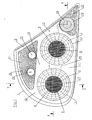
- the multi-chamber lamp for vehicles has an existing plastic luminaire housing (1), the front opening is closed by a translucent lens (6).
- the closure plate (6) is sealed with its outer circumferential edge sealed to the outer peripheral edge of the lamp housing (1).
- the rear wall of the luminaire housing (1) forms the cup-shaped reflectors (2, 3, 20, 21, 22), which are provided with a facet-like structured reflection surface (12).
- the reflection surface (12) is provided with a reflective surface.
- light sources formed by lamps (4, 5, 14, 24, 25) are arranged, which pass through reflector openings and in sockets (26) on the back of the lamp housing (1 ) are held.
- the reflectors (2, 3) are circular in shape at their light exit surface (11) and are surrounded by a front edge (17) of the luminaire housing (1) pointing in the light exit direction.
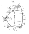
- the reflectors (2, 3) are each covered by a circular translucent intermediate disc (7 or 8).
- the intermediate discs (7, 8) have a shielding device (9) in their central area.
- the shielding device (9) is formed by a retroreflector.
- the retroreflector consists of a cup-shaped circular disc, which rests with its peripheral edge at the bottom of a correspondingly shaped recess (27) which is introduced into the side of the intermediate disc (7 or 8) facing the closure disc (6).
- the the Optics for the reflector (9) having disc is tightly welded to the washer (7 or 8).
- the intermediate disks (7 and 8) have an annular, optically-free region (23) running around the shielding device (9). This annular area (23) adjoins with its outer peripheral edge to the front edges (17) of the luminaire housing (1) surrounding the reflectors (2, 3).
- the closure disk (6) and the annular optically-free regions (23) of the intermediate disks (7, 8) have a smooth front and rear side. Therefore, the facet-like structured reflection surfaces (12) of the reflectors (2, 3) are clearly visible through the closure disk (6) and the annular regions (23) of the intermediate disks (7, 8).
- the reflectors (2, 3) are used to generate the tail light, wherein the reflector (3) additionally serves to generate the brake light.
- the reflector (20) serves to generate the reversing light and the reflector (21) for generating the flashing light.
- the triangular reflector (22) is arranged in an acute-angled corner of the luminaire housing (1).
- the reflector (22) associated light source (14) is surrounded by a light-transmitting light hood (15).
- the light hood (15) has on its top surface a shielding device (16) formed by optical elements.
- the optical elements of the shielding device (16) direct the light emerging directly from the light source (14).
- the reflector (22) and the optical elements of the light hood (16) are used to generate a rear fog light.
- the light hood (15) is integrally connected by a connecting piece (13) with the intermediate disc (8), while the intermediate discs (7, 8) via a connecting piece (28) are integrally connected.
- a covering device (10) is arranged between the closure plate (6) and the reflectors (2, 3, 20, 21, 22) and the intermediate discs (7, 8).
- the covering device (10) is formed by a frame-like cover part, which is made of plastic and in each case has a circular opening for the reflectors (2 and 3).
- the frame-like cover member (10) extends with a rear edge (18) delimiting the two openings adjacent to the front side of the optically-free region (23) of the intermediate disc (7 or 8).
- the cover (10) extends, starting from the rear edge (18), to near the inside of the lens (6).
- the cover member (10) is provided on its outer side with a reflective surface.
- the cover (10) has above the reflectors (2, 3) on a common opening for the directly adjacent reflectors (20, 21).
- the cover extends, except for the area of the reflector (22), with its outer edge to the outer edge of the lamp housing (1) and thus covers the areas between the reflectors (2, 3, 20, 21) and between the reflectors (2, 3, 20, 21) and the outer edge of the lamp housing from.
- the cover member (10) extends to the light hood (15) associated with the reflector (22) and thus defines one side of the reflector (22) while the other two sides of the triangular reflector (22) extend through the outer rim of the lamp housing (1) are limited.
- the closure plate (6) and the intermediate discs (7, 8) are fixed by means of holding elements (19) self-locking on the back of the lamp housing (1).
- the intermediate discs (7, 8) and the light hood (15) and / or the closure disc (6) can serve as a filter.
- the bulb (25) for flashing light has a yellow-colored glass bulb.
- the closure disk (6) has a window (29) without filter function in the region of the reflectors (20, 21).
- the closure plate (6) consists, except for the window (29), of two layers (30, 31).
- the layers (30, 31) are sprayed together, wherein the layer (30) extends on the outside and is crystal clear and without filter function, while the layer (31) extends on the inside of the lens (3) and is colored red.
Landscapes
- Engineering & Computer Science (AREA)
- General Engineering & Computer Science (AREA)
- Mechanical Engineering (AREA)
- Non-Portable Lighting Devices Or Systems Thereof (AREA)
Claims (10)
- Feu à chambres multiples pour véhicules, avec un boîtier de feu (1) présentant plusieurs réflecteurs (2, 3, 20, 21, 22), avec une glace de fermeture (6) commune aux réflecteurs (2, 3, 20, 21, 22) et avec au moins une glace intermédiaire (7, 8) qui s'étend sur toute la surface de sortie de lumière de l'un au moins des réflecteurs (2, 3), caractérisé en ce que- la glace de fermeture (6) de même que la glace intermédiaire (7, 8) sont réalisées sans éléments optiques du moins dans des zones partielles,- la glace intermédiaire (7, 8) porte un système de blindage (9) pour une source lumineuse (4, 5) associée au réflecteur (2, 3) et entoure le système de blindage (9) avec une zone sans éléments optiques (23),- au moins le réflecteur (2, 3) muni de la glace intermédiaire (7, 8) est entouré complètement par un dispositif de recouvrement (10) qui masque le bord périphérique extérieur de la glace intermédiaire (7, 8) et l'intérieur du boîtier de feu (1) aux regards de l'extérieur.
- Feu à chambres multiples selon la revendication 1, caractérisé en ce que le système de blindage (9) est disposé dans une zone centrale de la glace intermédiaire (7, 8) et est adapté par son bord périphérique extérieur au contour du bord arrière (18) du dispositif de recouvrement (9) adjacent à la glace intermédiaire (7, 8).
- Feu à chambres multiples selon la revendication 1 ou la revendication 2, caractérisé en ce que la glace intermédiaire (7, 8) est adjacente par sa face arrière à un bord avant (17) du boîtier de feu (1) entourant le réflecteur (2, 3) et par sa face avant à un bord périphérique arrière (18) du dispositif de recouvrement (10).
- Feu à chambres multiples selon l'une des revendications 1 à 3, caractérisé en ce qu'au moins deux glaces intermédiaires (7, 8) voisines associées chacune à un réflecteur (2 ou 3) sont réalisées d'une seule pièce et sont entourées sur leur périmètre par le dispositif de recouvrement (10).
- Feu à chambres multiples selon l'une des revendications 1 à 4, caractérisé en ce que la glace intermédiaire (7, 8) munie d'un système de blindage (9) est réalisée d'une seul tenant par l'intermédiaire d'une pièce de liaison (13) avec une calotte de lampe (15) dans laquelle se loge une source lumineuse (14), la pièce de liaison (13) étant masquée par le dispositif de recouvrement (10) et au moins la surface de recouvrement de la calotte de lampe (15) présentant un dispositif de blindage (16).
- Feu à chambres multiples selon l'une des revendications 1 à 5, caractérisé en ce que le système de blindage (9) porté par la glace intermédiaire (7, 8) est formé par des éléments optiques.
- Feu à chambres multiples selon l'une des revendications 1 à 6, caractérisé en ce que le système de blindage (9) porté par la glace intermédiaire (7, 8) est formé par un élément réfléchissant.
- Feu à chambres multiples selon l'une des revendications 1 à 7, caractérisé en ce qu'au moins les réflecteurs (2, 3, 22) munis d'un système ou dispositif de blindage (9 ou 16) présentent une surface réfléchissante structurée à facettes (12).
- Feu à chambres multiples selon l'une des revendications 1 à 8, caractérisé en ce qu'une pièce de recouvrement en forme de cadre disposée entre les réflecteurs (2, 3, 20, 21, 22) et la glace de fermeture (6) sert de dispositif de recouvrement (10).
- Feu à chambres multiples selon la revendication 9, caractérisé en ce que la glace intermédiaire (7, 8) de même que la pièce de recouvrement (10) sont munis d'éléments de retenue (19) qui sont reliés automatiquement au boîtier de feu (1) et recouverts par la pièce de recouvrement (10).
Applications Claiming Priority (2)
| Application Number | Priority Date | Filing Date | Title |
|---|---|---|---|
| DE19820656A DE19820656A1 (de) | 1998-05-08 | 1998-05-08 | Mehrkammerleuchte für Fahrzeuge |
| DE19820656 | 1998-05-08 |
Publications (3)
| Publication Number | Publication Date |
|---|---|
| EP0955207A2 EP0955207A2 (fr) | 1999-11-10 |
| EP0955207A3 EP0955207A3 (fr) | 2001-04-25 |
| EP0955207B1 true EP0955207B1 (fr) | 2007-09-05 |
Family
ID=7867123
Family Applications (1)
| Application Number | Title | Priority Date | Filing Date |
|---|---|---|---|
| EP99108939A Expired - Lifetime EP0955207B1 (fr) | 1998-05-08 | 1999-05-05 | Feu multiple pour véhicules automobiles |
Country Status (3)
| Country | Link |
|---|---|
| US (1) | US6296382B1 (fr) |
| EP (1) | EP0955207B1 (fr) |
| DE (2) | DE19820656A1 (fr) |
Families Citing this family (49)
| Publication number | Priority date | Publication date | Assignee | Title |
|---|---|---|---|---|
| DE10019556A1 (de) * | 2000-04-20 | 2001-10-25 | Hella Kg Hueck & Co | Reflektor für eine Fahrzeugleuchte |
| JP2002050207A (ja) * | 2000-08-02 | 2002-02-15 | Koito Mfg Co Ltd | 車両用灯具 |
| JP3839237B2 (ja) * | 2000-09-18 | 2006-11-01 | 株式会社小糸製作所 | 車両用灯具 |
| DE10053549B4 (de) * | 2000-10-28 | 2009-04-02 | Hella Kgaa Hueck & Co. | Signalleuchte |
| US6454433B1 (en) * | 2001-05-24 | 2002-09-24 | Eveready Battery Company, Inc. | Dual faceted reflector |
| USD467019S1 (en) | 2001-07-25 | 2002-12-10 | Brian A. Horowitz | Tail lens assembly |
| USD464748S1 (en) | 2001-07-25 | 2002-10-22 | Brian A. Horowitz | Replacement tail lens assembly |
| USD456919S1 (en) | 2001-07-25 | 2002-05-07 | Brian A. Horowitz | Replacement tail lens assembly |
| USD458397S1 (en) | 2001-08-16 | 2002-06-04 | Brian A. Horowitz | Lens assembly for headlamp |
| USD458701S1 (en) | 2001-08-21 | 2002-06-11 | Brian A. Horowitz | Tail lamp assembly |
| USD460574S1 (en) | 2001-08-21 | 2002-07-16 | Brian A. Horowitz | Tail lens assembly |
| USD461919S1 (en) | 2001-08-21 | 2002-08-20 | Brian A. Horowitz | Tail lens assembly for pick ups |
| USD457975S1 (en) | 2001-08-24 | 2002-05-28 | Brian A. Horowitz | Tail lens assembly |
| USD457258S1 (en) | 2001-08-24 | 2002-05-14 | Brian A. Horowitz | Tail lens assembly |
| USD459508S1 (en) | 2002-01-14 | 2002-06-25 | Brian A. Horowitz | Tail lens assembly |
| USD459507S1 (en) | 2002-01-14 | 2002-06-25 | Brian A. Horowitz | Tail lens assembly |
| USD458398S1 (en) | 2002-01-14 | 2002-06-04 | Brian A. Horowitz | Tail lens assembly |
| USD460833S1 (en) | 2002-01-14 | 2002-07-23 | Brian A. Horowitz | Tail lens assembly |
| USD459506S1 (en) | 2002-01-14 | 2002-06-25 | Brian A. Horowitz | Tail lens assembly |
| USD459510S1 (en) | 2002-02-08 | 2002-06-25 | Brian A. Horowitz | Tail lens assembly |
| USD460205S1 (en) | 2002-02-08 | 2002-07-09 | Brian A. Horowitz | Tail lens assembly |
| USD459821S1 (en) | 2002-02-08 | 2002-07-02 | Brian A. Horowitz | Tail lens assembly |
| USD459509S1 (en) | 2002-02-08 | 2002-06-25 | Brian A. Horowitz | Tail lens assembly |
| USD462800S1 (en) | 2002-02-14 | 2002-09-10 | Brian A. Horowitz | Tail lens assembly |
| USD469194S1 (en) | 2002-06-03 | 2003-01-21 | Brian A. Horowitz | Tail lens assembly |
| USD469554S1 (en) | 2002-06-03 | 2003-01-28 | Brian A. Horowitz | Tail lens assembly |
| DE10230277A1 (de) * | 2002-06-29 | 2004-01-22 | Bayerische Motoren Werke Ag | Leuchtenvorrichtung |
| US7025487B2 (en) * | 2002-06-29 | 2006-04-11 | Bayerische Motoren Werke Aktiengesellschaft | Lighting device |
| DE10302460A1 (de) * | 2003-01-23 | 2004-08-12 | Bayerische Motoren Werke Ag | Fahrzeugleuchte und Verfahren zur Anzeige unterschiedlicher Signalbilder einer Fahrzeugleuchte |
| USD495821S1 (en) | 2003-04-28 | 2004-09-07 | Grand General Accessories Manufacturing Inc. | Elliptical reflector for multi-LED vehicle lights |
| DE10333026A1 (de) * | 2003-07-21 | 2005-02-10 | Hella Kgaa Hueck & Co. | Beleuchtungseinrichtung für Fahrzeuge |
| USD486929S1 (en) | 2003-08-05 | 2004-02-17 | American Products Company, Inc. | Taillight assembly |
| US7527440B1 (en) | 2006-06-05 | 2009-05-05 | White Osborn L | Triangular vehicle light apparatus with camera |
| DE102007033709A1 (de) | 2007-07-17 | 2009-01-22 | Volkswagen Ag | Fahrzeugleuchtvorrichtung mit einer lichtstreuenden Zwischenlichtscheibe |
| DE102007033711A1 (de) | 2007-07-17 | 2009-01-22 | Volkswagen Ag | Fahrzeugleuchtvorrichtung mit einem Zusatzreflektor zum seitlichen Umlenken eines Lichtteils einer Lichtquelle |
| DE102008010487A1 (de) * | 2008-02-22 | 2009-08-27 | GM Global Technology Operations, Inc., Detroit | Fahrzeugleuchte |
| US7891835B2 (en) | 2008-07-15 | 2011-02-22 | Ruud Lighting, Inc. | Light-directing apparatus with protected reflector-shield and lighting fixture utilizing same |
| FR2941282B1 (fr) * | 2009-01-16 | 2013-10-18 | Peugeot Citroen Automobiles Sa | Masque a cache de lumiere pour un bloc optique de vehicule automobile |
| KR101827018B1 (ko) | 2009-12-21 | 2018-02-07 | 쓰리엠 이노베이티브 프로퍼티즈 컴파니 | 반투과형 물품 및 광 조립체 |
| JP5525277B2 (ja) * | 2010-02-10 | 2014-06-18 | 株式会社小糸製作所 | カメラを内蔵した車両用灯具 |
| WO2012151249A1 (fr) * | 2011-05-02 | 2012-11-08 | Peterson Manufacturing Company | Lampe d'éclairage dotée de doubles fonctions de faisceau |
| JP2014143071A (ja) * | 2013-01-24 | 2014-08-07 | Stanley Electric Co Ltd | 車両用灯具 |
| JP6125308B2 (ja) * | 2013-04-24 | 2017-05-10 | 本田技研工業株式会社 | 車両用尾灯装置 |
| FR3007503A1 (fr) * | 2013-06-20 | 2014-12-26 | Valeo Vision | Dispositif d'eclairage et/ou de signalisation pour equiper un vehicule automobile |
| KR101992183B1 (ko) * | 2017-07-10 | 2019-06-24 | 엘지전자 주식회사 | 차량용 램프 및 차량 |
| WO2020192858A1 (fr) * | 2019-03-27 | 2020-10-01 | HELLA GmbH & Co. KGaA | Dispositif d'éclairage pour véhicules |
| USD1001328S1 (en) * | 2019-09-09 | 2023-10-10 | Chen Shu Yueh | Light frame for automobile |
| DE102020127218B4 (de) | 2020-10-15 | 2023-04-27 | Marelli Automotive Lighting Reutlingen (Germany) GmbH | Reflektorbauteil für eine Kraftfahrzeugbeleuchtungseinrichtung |
| FR3146846A1 (fr) * | 2023-03-22 | 2024-09-27 | Psa Automobiles Sa | Bloc optique de véhicule à pièce réflectrice monobloc pour des fonctions de feu |
Citations (2)
| Publication number | Priority date | Publication date | Assignee | Title |
|---|---|---|---|---|
| US5558423A (en) * | 1994-12-17 | 1996-09-24 | Hella Kg Hueck & Co. | Headlights for motor vehicles |
| US5582480A (en) * | 1994-05-20 | 1996-12-10 | Reitter & Schefenacker Gmbh & Co. Kg | Light assembly for motor vehicles |
Family Cites Families (20)
| Publication number | Priority date | Publication date | Assignee | Title |
|---|---|---|---|---|
| FR2487041A1 (fr) * | 1980-07-17 | 1982-01-22 | Seima | Dispositif d'eclairage et de signalisation, notamment pour vehicules automobiles |
| FR2508597A1 (fr) * | 1981-06-30 | 1982-12-31 | Cibie Projecteurs | Feu, notamment pour la signalisation des vehicules automobiles |
| IT1144616B (it) * | 1981-07-31 | 1986-10-29 | Fiat Auto Spa | Fanale anteriore indicatore di direzione per autoveicoli |
| DE3711394A1 (de) * | 1987-04-04 | 1988-11-03 | Ullmann Ulo Werk | Reflektor fuer eine leuchte |
| DE3877561D1 (de) * | 1988-05-06 | 1993-02-25 | Hella Kg Hueck & Co | Mehrkammerleuchte fuer kraftfahrzeuge. |
| US5117335A (en) * | 1989-12-28 | 1992-05-26 | Koito Manufacturing Co., Ltd. | Headlight for vehicle |
| DE9001659U1 (de) | 1990-02-13 | 1990-04-19 | Hella KG Hueck & Co, 4780 Lippstadt | Heckleuchte für Fahrzeuge |
| JP2626199B2 (ja) * | 1990-07-25 | 1997-07-02 | 日産自動車株式会社 | 車両用放電灯ヘッドランプ |
| JP2610088B2 (ja) * | 1993-03-08 | 1997-05-14 | 株式会社小糸製作所 | 補助ランプ内蔵自動車用ヘッドランプ |
| JPH06283002A (ja) * | 1993-03-26 | 1994-10-07 | Koito Mfg Co Ltd | 自動車用ヘッドランプ |
| JP2777049B2 (ja) * | 1993-07-23 | 1998-07-16 | 株式会社小糸製作所 | 自動車用複合ヘッドランプ |
| JP2787415B2 (ja) * | 1994-03-28 | 1998-08-20 | 株式会社小糸製作所 | 車輌用標識灯 |
| IT1267221B1 (it) * | 1994-04-20 | 1997-01-28 | Seima Italiana Spa | Fanale per autoveicoli con riflettore a lenti |
| JP3214594B2 (ja) * | 1994-10-17 | 2001-10-02 | 株式会社小糸製作所 | 自動車用灯具 |
| JP3193604B2 (ja) * | 1995-12-25 | 2001-07-30 | 株式会社小糸製作所 | 放電バルブを有する車両用灯具 |
| FR2745365B1 (fr) * | 1996-02-23 | 1998-05-07 | Valeo Vision | Feu de signalisation a moyens perfectionnes d'etalement de la lumiere |
| US5685634A (en) * | 1996-08-22 | 1997-11-11 | Display Solutions, Inc. | Lens assembly for matrix lamp displays |
| FR2753521B1 (fr) * | 1996-09-18 | 1998-12-04 | Valeo Vision | Feu de signalisation a cache de lampe perfectionne pour vehicule automobile |
| DE19744715C1 (de) * | 1997-10-10 | 1999-04-22 | Daimler Chrysler Ag | Beleuchtungsvorrichtung für das Heck eines Fahrzeuges |
| JP3005687B2 (ja) * | 1998-05-28 | 2000-01-31 | スタンレー電気株式会社 | 灯 具 |
-
1998
- 1998-05-08 DE DE19820656A patent/DE19820656A1/de not_active Withdrawn
-
1999
- 1999-05-05 DE DE59914486T patent/DE59914486D1/de not_active Expired - Lifetime
- 1999-05-05 EP EP99108939A patent/EP0955207B1/fr not_active Expired - Lifetime
- 1999-05-06 US US09/304,261 patent/US6296382B1/en not_active Expired - Fee Related
Patent Citations (2)
| Publication number | Priority date | Publication date | Assignee | Title |
|---|---|---|---|---|
| US5582480A (en) * | 1994-05-20 | 1996-12-10 | Reitter & Schefenacker Gmbh & Co. Kg | Light assembly for motor vehicles |
| US5558423A (en) * | 1994-12-17 | 1996-09-24 | Hella Kg Hueck & Co. | Headlights for motor vehicles |
Also Published As
| Publication number | Publication date |
|---|---|
| DE19820656A1 (de) | 1999-11-11 |
| EP0955207A2 (fr) | 1999-11-10 |
| DE59914486D1 (de) | 2007-10-18 |
| EP0955207A3 (fr) | 2001-04-25 |
| US6296382B1 (en) | 2001-10-02 |
Similar Documents
| Publication | Publication Date | Title |
|---|---|---|
| EP0955207B1 (fr) | Feu multiple pour véhicules automobiles | |
| EP0442095B1 (fr) | Feu arrière de véhicule | |
| DE4417695C2 (de) | Kraftfahrzeugleuchte | |
| EP1914118A2 (fr) | Miroir extérieur avec moyen lumineux | |
| DE10249113A1 (de) | Leuchte, insbesondere Heckleuchte, für Fahrzeuge, vorzugsweise Kraftfahrzeuge | |
| DE10023754A1 (de) | Fahrzeugleuchte | |
| DE3305218C2 (de) | Mehrkammerleuchte für Kraftfahrzeuge | |
| DE3843522C2 (fr) | ||
| DE69401314T2 (de) | Stylistisches oder optisches Element- mit glänzendem Aussehen und neutraler Farbe- für Kfz-Beleuchtungs- oder Anzeige-Scheinwerfer | |
| DE3828522C2 (de) | Kraftfahrzeugleuchte | |
| EP1089033B1 (fr) | Dispositif d' éclairage pour véhicules | |
| DE29807774U1 (de) | Leuchte für Fahrzeuge, insbesondere Heckleuchte für Fahrzeuge | |
| DE102004011600A1 (de) | Rückstrahler für Heckleuchten von Fahrzeugen, vorzugsweise von Kraftfahrzeugen | |
| DE3306481A1 (de) | Lichtabgabevorrichtung fuer kraftfahrzeuge | |
| DE19721596C2 (de) | Leuchte, insbesondere Heckleuchte, für Fahrzeuge, vorzugsweise Kraftfahrzeuge | |
| EP0679551B1 (fr) | Unité d'éclairage pour véhicule | |
| EP0340328B1 (fr) | Feu multiple pour véhicules automobiles | |
| DE19753762A1 (de) | Signalleuchte, insbesondere Kombinationsheckleuchte eines Fahrzeuges | |
| DE29809619U1 (de) | Fahrzeugscheinwerfer | |
| EP1004473B1 (fr) | Unité d'éclairage pour véhicule | |
| DE3142475C2 (de) | Fahrzeugleuchte, insbesondere für Zweiradfahrzeuge | |
| DE102011113627A1 (de) | Lichtscheibe für eine Fahrzeugleuchte und Fahrzeugleute mit einer solchen Lichtscheibe | |
| DE19838911B4 (de) | Beleuchtungseinrichtung eines Fahrzeugs | |
| DE10241023A1 (de) | Leuchte für Fahrzeuge, insbesondere Heckleuchte für Kraftfahrzeuge | |
| DE29709279U1 (de) | Kraftfahrzeugleuchte, insbesondere Blinkleuchte |
Legal Events
| Date | Code | Title | Description |
|---|---|---|---|
| PUAI | Public reference made under article 153(3) epc to a published international application that has entered the european phase |
Free format text: ORIGINAL CODE: 0009012 |
|
| AK | Designated contracting states |
Kind code of ref document: A2 Designated state(s): DE ES FR GB IT |
|
| AX | Request for extension of the european patent |
Free format text: AL;LT;LV;MK;RO;SI |
|
| PUAL | Search report despatched |
Free format text: ORIGINAL CODE: 0009013 |
|
| AK | Designated contracting states |
Kind code of ref document: A3 Designated state(s): AT BE CH CY DE DK ES FI FR GB GR IE IT LI LU MC NL PT SE |
|
| AX | Request for extension of the european patent |
Free format text: AL;LT;LV;MK;RO;SI |
|
| 17P | Request for examination filed |
Effective date: 20010925 |
|
| AKX | Designation fees paid |
Free format text: DE ES FR GB IT |
|
| RAP1 | Party data changed (applicant data changed or rights of an application transferred) |
Owner name: HELLA KGAA HUECK & CO. |
|
| 17Q | First examination report despatched |
Effective date: 20061114 |
|
| GRAP | Despatch of communication of intention to grant a patent |
Free format text: ORIGINAL CODE: EPIDOSNIGR1 |
|
| GRAS | Grant fee paid |
Free format text: ORIGINAL CODE: EPIDOSNIGR3 |
|
| GRAA | (expected) grant |
Free format text: ORIGINAL CODE: 0009210 |
|
| AK | Designated contracting states |
Kind code of ref document: B1 Designated state(s): DE ES FR GB IT |
|
| REG | Reference to a national code |
Ref country code: GB Ref legal event code: FG4D Free format text: NOT ENGLISH |
|
| RIC2 | Information provided on ipc code assigned after grant |
Ipc: F21V 9/08 20060101ALI20070731BHEP Ipc: B60Q 1/26 20060101AFI20070731BHEP |
|
| REF | Corresponds to: |
Ref document number: 59914486 Country of ref document: DE Date of ref document: 20071018 Kind code of ref document: P |
|
| ET | Fr: translation filed | ||
| PG25 | Lapsed in a contracting state [announced via postgrant information from national office to epo] |
Ref country code: ES Free format text: LAPSE BECAUSE OF FAILURE TO SUBMIT A TRANSLATION OF THE DESCRIPTION OR TO PAY THE FEE WITHIN THE PRESCRIBED TIME-LIMIT Effective date: 20071216 |
|
| GBV | Gb: ep patent (uk) treated as always having been void in accordance with gb section 77(7)/1977 [no translation filed] | ||
| PG25 | Lapsed in a contracting state [announced via postgrant information from national office to epo] |
Ref country code: GB Free format text: LAPSE BECAUSE OF FAILURE TO SUBMIT A TRANSLATION OF THE DESCRIPTION OR TO PAY THE FEE WITHIN THE PRESCRIBED TIME-LIMIT Effective date: 20070905 |
|
| PLBE | No opposition filed within time limit |
Free format text: ORIGINAL CODE: 0009261 |
|
| STAA | Information on the status of an ep patent application or granted ep patent |
Free format text: STATUS: NO OPPOSITION FILED WITHIN TIME LIMIT |
|
| 26N | No opposition filed |
Effective date: 20080606 |
|
| PGFP | Annual fee paid to national office [announced via postgrant information from national office to epo] |
Ref country code: FR Payment date: 20100525 Year of fee payment: 12 |
|
| PGFP | Annual fee paid to national office [announced via postgrant information from national office to epo] |
Ref country code: IT Payment date: 20100515 Year of fee payment: 12 Ref country code: DE Payment date: 20100430 Year of fee payment: 12 |
|
| REG | Reference to a national code |
Ref country code: DE Ref legal event code: R119 Ref document number: 59914486 Country of ref document: DE |
|
| REG | Reference to a national code |
Ref country code: DE Ref legal event code: R119 Ref document number: 59914486 Country of ref document: DE |
|
| REG | Reference to a national code |
Ref country code: FR Ref legal event code: ST Effective date: 20120131 |
|
| PG25 | Lapsed in a contracting state [announced via postgrant information from national office to epo] |
Ref country code: IT Free format text: LAPSE BECAUSE OF NON-PAYMENT OF DUE FEES Effective date: 20110505 |
|
| PG25 | Lapsed in a contracting state [announced via postgrant information from national office to epo] |
Ref country code: FR Free format text: LAPSE BECAUSE OF NON-PAYMENT OF DUE FEES Effective date: 20110531 |
|
| PG25 | Lapsed in a contracting state [announced via postgrant information from national office to epo] |
Ref country code: DE Free format text: LAPSE BECAUSE OF NON-PAYMENT OF DUE FEES Effective date: 20111130 |