EP0953538A2 - Ascenseur de type tracté - Google Patents
Ascenseur de type tracté Download PDFInfo
- Publication number
- EP0953538A2 EP0953538A2 EP99107460A EP99107460A EP0953538A2 EP 0953538 A2 EP0953538 A2 EP 0953538A2 EP 99107460 A EP99107460 A EP 99107460A EP 99107460 A EP99107460 A EP 99107460A EP 0953538 A2 EP0953538 A2 EP 0953538A2
- Authority
- EP
- European Patent Office
- Prior art keywords
- elevator
- path
- guide rails
- elevator car
- car
- Prior art date
- Legal status (The legal status is an assumption and is not a legal conclusion. Google has not performed a legal analysis and makes no representation as to the accuracy of the status listed.)
- Granted
Links
- 239000000725 suspension Substances 0.000 claims abstract description 139
- 230000000630 rising effect Effects 0.000 claims abstract description 64
- 230000007246 mechanism Effects 0.000 claims abstract description 43
- 230000005484 gravity Effects 0.000 claims description 9
- 238000000034 method Methods 0.000 description 9
- 230000004048 modification Effects 0.000 description 9
- 238000012986 modification Methods 0.000 description 9
- 230000008569 process Effects 0.000 description 9
- 230000008901 benefit Effects 0.000 description 7
- 238000004804 winding Methods 0.000 description 6
- 230000001965 increasing effect Effects 0.000 description 4
- 230000009471 action Effects 0.000 description 3
- 230000000712 assembly Effects 0.000 description 3
- 238000000429 assembly Methods 0.000 description 3
- 230000001360 synchronised effect Effects 0.000 description 3
- 230000003028 elevating effect Effects 0.000 description 2
- 230000001747 exhibiting effect Effects 0.000 description 2
- 230000006872 improvement Effects 0.000 description 2
- 238000012423 maintenance Methods 0.000 description 2
- 230000003796 beauty Effects 0.000 description 1
- 230000000694 effects Effects 0.000 description 1
- 238000007689 inspection Methods 0.000 description 1
- 238000005096 rolling process Methods 0.000 description 1
Images


Classifications
-
- B—PERFORMING OPERATIONS; TRANSPORTING
- B66—HOISTING; LIFTING; HAULING
- B66B—ELEVATORS; ESCALATORS OR MOVING WALKWAYS
- B66B11/00—Main component parts of lifts in, or associated with, buildings or other structures
- B66B11/0065—Roping
- B66B11/008—Roping with hoisting rope or cable operated by frictional engagement with a winding drum or sheave
-
- B—PERFORMING OPERATIONS; TRANSPORTING
- B66—HOISTING; LIFTING; HAULING
- B66B—ELEVATORS; ESCALATORS OR MOVING WALKWAYS
- B66B11/00—Main component parts of lifts in, or associated with, buildings or other structures
-
- B—PERFORMING OPERATIONS; TRANSPORTING
- B66—HOISTING; LIFTING; HAULING
- B66B—ELEVATORS; ESCALATORS OR MOVING WALKWAYS
- B66B13/00—Doors, gates, or other apparatus controlling access to, or exit from, cages or lift well landings
Definitions
- the present invention relates to an improvement of a traction type of elevator apparatus having a driving mechanism disposed in an elevator path (or hoistway) of the apparatus.
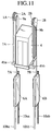
- Japanese Patent No. 2593288 discloses a traction sheave elevator, as shown in Fig. 1.
- a flattened driving mechanism 2 having a traction sheave 1 is disposed between a side wall 3a in an elevator path 3 and a space defined by projected planes of an elevator car 4 in the upward and downward directions.
- a hoisting (suspension) rope 7 is wound about a sheave 5a beneath the car 4 and a sheave 5b above a balance weight 6, while both ends of the hoisting rope 7 are fixed on a top wall 3b defining the elevator path 3.
- a pit 3c in the elevator path 3 is positioned under a level 3d of the first floor (1F).
- the elevator of Fig. 1 does adopt a structure where the car 4 is driven like a movable pulley while winding the suspension rope 7 about the sheave 5a under the car 4. Owing to this arrangement, it is possible to reduce the capacity of a motor of the driving mechanism relatively and minimize a space occupied by the driving mechanism, together with the effective use of the space above the car 4.
- Japanese Unexamined Patent Publication (kokai) No. 9-156855 discloses another elevator apparatus shown in Fig. 2.
- the flattened driving mechanism 2 is arranged in the upper space of the balance weight 6 and adapted so as to suspend the car 4 through turning sheaves 8a, 8b and 8c.
- the driving mechanism 2 having the traction sheave 1 is disposed between a side wall 3a in an elevator path 3 and a space defined by projected planes of an elevator car 4 in the upward and downward directions, the arrangement allows to minimize a space that the whole apparatus does occupy without providing the machine room on the roof, so that the elevator apparatus can be provided while exhibiting high efficiency in utilizing the space.
- an elevator apparatus comprising:
- the drive of the elevator car at the same speed as the suspension rope can be realized owing to the achievement of roping ratio of 1 : 1.
- the elevator car is connected with the suspension rope in a position below the ceiling of the elevator car and there is provided no turning sheave etc. in a space above the elevator car, the upper area of the elevator path can be effectively utilized thereby to provide a high-speed and compact elevator apparatus.
- the driving unit comprises a plurality of driving mechanisms each having a traction sheave and the suspension rope is wound about each traction sheave of the driving mechanisms and finally fixed to the elevator car and the balance weight.
- the driving mechanisms are arranged up and down in the elevator path, while the suspension rope is wound round the traction sheave associated with the upper driving mechanism with a plurality of turns.
- the driving mechanisms are arranged left and right in the elevator path, so that respective planes of the traction sheaves associated with the left and upper driving mechanism coincide with each other substantially.
- the driving unit is constituted by the plural driving mechanisms, it is possible to realize to provide the elevator apparatus with high-speed operation and large transportation capacity.
- one of the elevator guide rails which is disposed on the side of the driving unit, has a H-shaped cross section and is arranged so that parallel side portions constituting the H-shaped cross section are opposite to a side wall of the elevator and that the elevator car is provided with two pairs of rollers for guiding the elevator car, each pair of rollers interposing one of the parallel side portions between the rollers on left and right sides of the parallel side portion.
- the elevator apparatus is provided with great rigidity, so that it can travel more stably.
- the elevator apparatus further comprises a L-shaped frame for mounting and carrying the elevator car thereon, the frame consisting of a vertical beam and a horizontal beam and that the horizontal beam is provided, at a tip thereof, with other rollers between which the other elevator guide rail disposed on the opposite side of the driving unit is interposed to guide the elevator car.
- the elevator apparatus can rise and fall more stably and the elevator car can be carried with such a simple structure, strongly.
- the suspension rope is divided into two routes of ropes whose ends are respectively fixed to different positions on opposite outer faces of the elevator car, while the different positions are symmetrical to each other in plan view of the elevator car.
- the suspension rope it is possible to provide the elevator car with its stable posture.
- the driving unit is disposed in the vicinity of a first floor in the elevator path.
- the driving unit it is possible to reduce the height of the ceiling of the elevator path to a minimum.
- the arrangement allows a worker to execute the maintenance and inspecting operation for the elevator apparatus near the ground, whereby the burden on the worker can be lightened.
- the weight guide rails are arranged so as to extend along opposite inner walls defining the elevator path and that the suspension ropes have respective ends fixed to the balance weights in pairs rising and falling under guidance of the weight guide rails and respective other ends fixed to the elevator car through the driving units in pairs.
- the driving units in pairs are respectively connected to the balance weights in pairs, it is possible to provide the elevator apparatus having large transportation capacity.
- suspension ropes in pairs have respective ends fixed on opposite outer faces of the elevator car and have respective other ends fixed on the single balance weight through the traction sheaves of the driving units provided corresponding to the opposite outer faces, the balance weight being attached along an inner wall of the elevator path behind the elevator car. Also in this preferable form, it is possible to provide the elevator apparatus having large transportation capacity.
- the driving unit is attached on either one of an inner wall and a roof wall of the elevator path.
- the burden applied on the elevator guide rails is lightened thereby to reduce the weight of the driving unit.
- an elevator apparatus comprising:
- the drive of the elevator car at the same speed as the suspension rope can be realized owing to the achievement of roping ratio of 1 : 1.
- the upper area of the elevator path can be effectively utilized thereby to provide the high-speed and large-capacity elevator apparatus.
- an elevator apparatus comprising:
- an elevator apparatus comprising:
- an elevator apparatus comprising:
- an elevator apparatus comprising:
- an elevator apparatus comprising:
- an elevator apparatus comprising:
- an elevator apparatus comprising:
- the weight guide rails are disposed on a side wall of the elevator path. This preferable arrangement is applicable to the elevator apparatus with an elevator path having a sufficient room in width.
- the weight guide rails are disposed on a back wall of the elevator path. This preferable arrangement is applicable to the elevator apparatus with an elevator path having a sufficient room in depth.
- the turning sheaves on either side face or back face of the elevator car are arranged so as to be symmetrical about a gravity center of the elevator when viewed from an upside of the elevator car. In this case, it is possible to prevent an excessive bias load from acting on the elevator guide rails or the like.
- the driving unit comprises a plurality of thin-type winders each having a traction sheave. In this case, it is possible to drive the large-sized elevator car under traction.
- the thin-type winders are driven by a single control device, synchronously. In this case, it is expected to simplify the structure of the elevator apparatus.
- an suspension (or hoisting) rope has one end coupled to an elevator car in a position below the roof of the elevator car. While, in common with the second group of the subsequent embodiments, the elevator car is provided, on one or both sides thereof, with a turning sheave around which the suspension rope is wound.
- Fig. 3 is a perspective view of an elevator apparatus in accordance with the first embodiment of the present invention and Fig. 4 is an enlarged plan view of the elevator apparatus of Fig. 3.
- a pair of elevator guide rails 9a, 9b each having a T-shaped cross section are attached to the side walls 3a defining the elevator path 3 through not-shown brackets.
- a hitch part 4b is formed so as to laterally project at a position below the roof 4c of the car 4.
- the hitch part 4b is connected to one end of the suspension rope 7 through a not-shown hitch spring.
- the "flat and thin" type of driving mechanism 2 is secured on the top of the guide rail 9a and provided with the traction sheave 1.
- the traction sheave 1 is accommodated in a clearance defined between the side wall 3a of the elevator path 3 and a space occupied by the elevator car 4 traveling up and down in the elevator path 3.
- the suspension rope 7 is wound round the traction sheave 1.
- Adjacent to the elevator guide rail 9a for the elevator car 4, a pair of weight guide rails 10a, 10b are arranged for guidance of the movement of the balance weight 6.
- the other end of the suspension rope 7 is connected to the upper end of the balance weight 6.
- both elevator car 4 and balance weight 6, which are coupled to the respective ends of the suspension rope 7, are moved up and down under the guidance of the guide rails 9a, 9b and 10a, 10b, respectively.
- the car roof 4c is capable of rising in excess of the height of the driving mechanism 2 owing to the arrangement where the elevator car 4 is connected to the suspension rope 7 at the hitch part 4b below the car roof 4c.
- both elevator car 4 and suspension rope 7 are driven at the same velocity thereby to realize the high-speed operation.
- the driving unit consisting of the traction sheave 1 and the driving mechanism 2 are accommodated in the clearance defined between the side wall 3a of the elevator path 3 and the space being occupied by the car 4 in the process of moving upward and downward, the car 4 can rise to the vicinity of the ceiling of the elevator path 3, so that it is possible to hold the height of the elevator path 3 to a minimum, thereby accomplishing the space-saving of the apparatus.
- the driving unit is constituted by the single driving mechanism 2 in the first embodiment, it may be constituted by two or more mechanisms in order to not only realize the high-speed elevator apparatus but large-capacity, in the modification.
- the driving unit is constituted by a plurality of driving mechanisms thereby realizing both high-speed and large-capacity elevator apparatus, with reference to Figs. 5 and 6.
- the flat and thin driving unit at the top of the rail 9a of T-shaped cross section is constituted by driving mechanisms 2A, 2B which are arranged in either vertical (Fig. 5) or horizontal (Fig. 6) direction of the apparatus, for driving traction sheaves 1A, 1B, respectively.
- the suspension rope 7 having one end connected to the lower balance weight 6 is wound around the upper half periphery of the upper traction sheave 1A and the sequent lower half periphery of the lower traction sheave 1B. Thereafter, through the upper half periphery of the upper traction sheave 1A again, the rope 7 is hung downwardly and finally connected to the hitch part 4b on the underside of the elevator car 4.
- a groove width of the sheave 1A is twice as large as the groove width of the lower traction sheave 1B.
- suspension rope 7 is twice wound around the upper half periphery of the upper traction sheave 1A in Fig. 5. Therefore, it means that the suspension rope 7 is connected to the balance weight 6 and the elevator car 4 through the winding of three quarters on the upper and lower sheaves 1A, 1B in total after all. The same thing can be said of the arrangement shown in Fig. 6.
- the elevator car 4 can be moved at high speed equal to that of the rope 7 and the elevator car 4 can be large-sized with the increased thrust by the traction sheaves 1A, 1B.
- the guide rails 9a, 9b are formed to have T-shaped cross sections in both first and second embodiments
- the guide rail 9a on one hand may be formed to have a H-shaped cross section in order to improve its rigidity in the modification. Then, it will be expected to provide the elevator apparatus capable of traveling more stable.
- one of the guide rails 9a and 9c i.e. the guide rail 9c is formed to have a H-shaped cross section, which is largely shown in Fig. 8, too.
- the guide rail 9c is fixed on the side wall 3a of the elevator path 3 by a not-shown bracket in a manner that parallel sides of the rail 9c oppose the elevator car 4.
- the flat and thin driving mechanism 2 having the traction sheave 1 is arranged on the top of the guide rail 9c and accommodated in the clearance defined between the side wall 3a of the elevator path 3 and the occupied space by the car 4 in the process of moving upward and downward.
- a L-shaped frame 11 is provided for carrying and supporting the car 4 at the center of gravity.
- the frame 11 is composed of a vertical beam 11a and a horizontal beam 11b.
- Respectively attached on the upper and lower sides of the vertical beam 11a are upper and lower guide roller assemblies 12a, 12b each of which has a plurality of rollers 12aa, 12ab guiding one (9ca) of parallel side portions of the guide rail 9c.
- the side portion 9ca close to the elevator car 4 is interposed between the roller 12aa and the accompanying roller 12aa and also interposed between the roller 12ab and the accompanying roller 12ab, on both sides of the portion 9ca.
- the horizontal beam 11b of the frame 11 is provided, at a tip thereof, with a roller assembly 12c which guides the movement of the elevator car 4 along the T-shaped cross-sectional guide rail 9a, as similar to the aforementioned embodiments.
- the rails 10a, 10b for the balance weight 6 are not shown in Figs. 7 and 8, the rails 10a, 10b are disposed adjacent to the guide rail 9c for the elevator car 4. Similarly, the suspension rope 7 having one end coupled to the top of the balance weight 6 and the other end coupled to the hitch part 4b below the L-shaped frame 11, is wound about the traction sheave 1.
- the elevator car 4 is guided by the upper and lower roller assemblies 12a, 12b while being supported by the vertical beam 11a. Then, the elevator's rolling about the longitudinal axis of the guide rail 9c can be restricted by the rollers 12aa, 12ab urging the side portion 9ca from the inside and outside.
- the elevator car 4 can be restricted from being swung back and forth owing to the guidance of the guide roller assembly 12c at the tip of the horizontal beam 11b while interposing the guide rail 9a, so that the stable rise and fall can be accomplished.
- the third embodiment it is possible to provide the space-saving and high-speed elevator apparatus without forming the exclusive machine room on the roof of the building, as similar to the first and second embodiments. Additionally, owing to the adoption of the guide rail 9c of H-shaped cross section exhibiting a high rigidity, it is possible to realize the stable rise and fall of the elevator car 4.
- the elevator car 4 can be carried with the simple structure, lightly and persistently.
- the single rope may be replaced with two or more suspension ropes 7 in view of the more stable and high-speed traveling of the car 4.
- the flat and thin driving mechanism 2 coupled to the traction sheave 1 is attached to either one of the guide rails 9a, 9b for guiding the elevator car 4 and accommodated in the space between the car 4 and the side wall 3a of the elevator path 3, as similar to the first to third embodiments.
- two sheaves 8d, 8e are arranged in parallel with both sides of the elevator car 4. Additionally, in position of the elevator path 3 besides the occupied space by the car 4 in the process of moving upward and downward, one sheave 8f is arranged so as to cross the sheaves 8d, 8e at an angle of 45 degrees.
- pitch parts 4ba, 4bb for connection with the suspension rope 7 are arranged symmetrically with each other about the gravity center of the elevator car 4. Further, the sheaves 8d, 8g corresponding to the hitch parts 4ba, 4bb are attached on the side walls 3a defining the elevator path 3 so as not to interfere with the occupied space by the car 4 in the process of moving upward and downward.
- suspension ropes 7 each having one end coupled to the balance weight 6 are wound round the traction sheave 1 through the sheave 8e attached to the top wall 3b above the weight 6 and thereafter, divided into different directions, i.e. two courses.
- Either of the so-divided suspension ropes 7 has one end connected with the elevator car 4 at the hitch part 4ba through the intermediary of the sheave 8d attached on the wall 3a. While, another suspension rope 7 has one end connected with the elevator car 4 at the hitch part 4bb through the intermediary of the sheave 8f attached on the side wall 3a at an angle of approx. 45 degrees and the sequent sheave 8g also attached on the right side wall 3a at an angle of approx. 45 degrees.
- the suspension ropes 7 divided into two routes operate to rise and fall the elevator car 4 via the sheaves 8d, 8f, 8g on one hand and the balance weight 6 via the sheave 8e on the other hand.
- the elevator car 4 can rise and fall at high speed equal to that of the suspension rope 7 due to the roping ratio of 1 : 1. Furthermore, since both sides of the elevator car 4 in the diagonal direction are being suspended by the suspension ropes 7 of two routes during the traveling, the car's posture can be stabilized. Again, owing to the arrangement where the driving unit and the respective sheaves 8d, 8e, 8f, 8g are arranged so as not to interfere with the occupied space by the car 4 in the process of moving upward and downward, it is possible to elevate the elevator car 4 so that the roof 4c reaches the vicinity of the roof wall of the elevator path 3, whereby the elevator apparatus including the elevator path 3 can be small-sized with the improvement of efficiency in using the elevator path 3.
- the elevator car's capacity would be increased when the hanging positions on both sides of the elevator car 4 are arranged so as to be symmetrical with each other about the gravity center of the car 4 and the elevator apparatus is provided, on left and right sides thereof, with the driving units as shown in Fig. 3.
- Guide rails 10aa, 10ba for a balance weight 6A are arranged adjacent to the guide rail 9a.
- guide rails 10ab, 10bb for another balance weight 6B are arranged adjacent to the guide rail 9b.
- hitch parts 4ba, 4bb are attached to the car 4, symmetrically with each other.
- Suspension ropes 7A, 7B having respective ends coupled to the hitch parts 4ba, 4bb are wound round the traction sheaves 1A, 1B and finally connected to the balance weights 6A, 6B, respectively.
- the driving mechanisms 2A, 2B on both sides of the car 4 are driven by the single control device, for the requirement of synchronous operation.
- the elevator car 4 is driven to rise and fall by the driving mechanisms 2A, 2B, so that a large thrust force is provided against the car 4.
- the moving velocity of the car 4 becomes to be equal to that of each suspension rope 7A, 7B moving at high speed.
- the driving mechanisms 2A, 2B are arranged so as not to interfere with the occupied space by the car 4 in the process of moving upward and downward, it is possible to reduce the height of the elevator path 3 without providing the exclusive machine room on the roof top etc.
- the respective positions of the suspension ropes 7A, 7B are established in symmetry with each other about the gravity center of the car 4, the moving car's posture can be stabilized, too.
- balance weights 6A, 6B are disposed on the left and right sides of the car 4 in the above-mentioned fifth embodiment, they may be replaced with the common balance weight in order to realize the apparatus of simple structure.
- the driving mechanisms 2A, 2B which have the traction sheaves 1A, 1B arranged in the vicinity of the guide rails 9a, 9b, respectively.
- the common balance weight 6 is adapted so as to rise and fall under the guidance of the rails 10a, 10b.
- the suspension ropes 7A, 7B respectively connected to the hitch parts 4ba, 4bb below the car roof 4c are wound round the traction sheaves 1A, 1B, respectively and the ropes 7A, 7B are coupled to the common balance weight 6 finally.
- the left and right driving mechanisms 2A, 2B are controlled by the single control unit, so that the elevator car 4 can rise and fall owing to the mechanisms' synchronous operation at the same speed. Again, the elevator car 4 does rise and fall at speed equal to those of the suspension ropes 7A, 7B owing to the thrust force by the driving mechanisms 2A, 2B.
- the driving unit and the sheaves 8ha, 6hb, 8ia, 8ib are arranged so as not to interfere with the occupied space by the car 4 in the process of moving upward and downward, it is possible to reduce the height of the elevator path 3 to a minimum.
- the driving unit is attached on either one of the top of the guide rail 9a and the wall of the elevator path 3 and also arranged so as not to interfere with the occupied space by the car 4 in the process of moving upward and downward.
- the driving unit may be arranged in the elevator path 3 adjacent to the first floor, provided that the driving unit does not interfere with the occupied space by the car 4 in the process of moving upward and downward.
- the driving unit 2 is positioned in the vicinity of the first floor (1F) of the elevator path, it would be possible to reduce a height of the roof of the elevator path to a minimum, as similar to the above-mentioned embodiments. Additionally, because of the work for maintenance and inspection in the neighborhood of ground, it is possible to lighten the burden on the workers.
- the driving unit 2 is arranged in the upper part of the elevator path or the vicinity of the first floor so as not to interfere with the movement of the elevator car 4, thereby restricting to increase the height of elevator path.
- the driving unit is disposed in a pit of the elevator path, the height of elevator path would be effectively utilized to reduce either height of the elevator path or height of the building.
- the driving unit consisting of the traction sheave and the driving mechanism 2 is arranged in the pit 3c of the elevator path 3.
- One end of the suspension rope 7 wound about the traction sheave 1 is connected to the hitch part 4b through a sheave 8j in the vicinity of the roof of the elevator path 3, while the other end of the rope 7 is connected to the balance weight 6 through a sheave 8k in the vicinity of the roof of the elevator path 3.
- the embodiment it is possible to make effective use of even the neighborhood of roof of the elevator path 3 in case of the elevation of the elevator car 4 and furthermore, the high-speed elevator can be provided due to the roping ratio of 1 : 1.
- the shown embodiment does adopt the single driving mechanism 2, for example, it may be replaced with a pair of driving units in the pit 3c for realizing the large-capacity, as similar to the units shown in Figs 11 to 13.
- FIGS 16 and 17 show the eighth embodiment of the invention.
- an elevator car 21 is guided by two parallel guide rails 20a, 20b mounted on side walls 24a of an elevator path (hoistway) 24 through not-shown brackets.
- a turning sheave 22 is attached on a side face 21a of the elevator car 21, namely, either one of the left and right faces on both sides of a front face 21b as the entrance for the elevator car 21 so that a rotational plane of the sheave 22 is parallel with the side face 21a.
- a suspension rope 23 is wound round the turning sheave 22, while the elevator car 21 is suspended by the suspension rope 23 through the turning sheave 22.
- a driving unit 26 Fixed on the top of the guide rail 20a on the side of the turning sheave 22 is a driving unit 26 which drives to rotate a flat and thin traction sheave 25 disposed between the side wall 24a of the elevator path 24 and the space being occupied by the rising and falling elevator car 21.
- the suspension rope 23 is wound round the traction sheave 25 and also wound or rewound in a "well bucket” manner by the rotation of the traction sheave 25.
- a pair of guide rails 27a, 27b for balance weight are arranged in a position adjacent to the guide rail 20a, for allowing a balance weight 28 to rise and fall under their guidance.
- Attached on the top of the balance weight 28 is a turning sheave 29 about which the suspension rope 23 is also wound to hang the weight 28.
- Both ends of the suspension rope 23 are connected to supporting members (not shown) and carried by the members, which are built in the ceiling of the elevator path 24 over the elevator car 21, through the intermediary of hitch springs also not shown in the figure.
- the elevator apparatus of the first embodiment operates as follows. With the drive of the driving unit 26, the traction sheave 25 is rotated and therefore, the suspension rope 23 rolled thereon is wound up and rewound, so that the elevator car 21 and balance weight 28 rise and fall in opposite directions, under the guidance of the guide rails 20a, 20b; 27a, 27b, respectively. Then, since the elevator car 21 is suspended by the suspension rope 23 through the turning sheave 22 disposed on the side face 21a under a ceiling (roof) face 21c, the elevator car 21 can be elevated in a manner that the ceiling face 21c moves upward in excess of the driving unit 26 in the elevator path 24.
- the elevator car 21 hung by the suspension rope 23 performs an action like a moving pulley due to the turning sheave 22, it is possible to reduce the power capacity required for the driving unit 26 in comparison with that required for the driving unit 26 in direct-hanging the car 21 by the traction sheave 25.
- the driving unit 26 is arranged in a space in the elevator path 24, between the side wall 24a of the elevator path 24 and the space being occupied by the rising and falling elevator car 21 and additionally, the elevator car 21 can rise and fall close to the ceiling and floor of the elevator path 24 without requiring any more space above or beneath the path 24, it is possible to establish a height of the path 24 to a minimum.
- the ninth embodiment will be described below, with reference to Figs. 18 and 19.
- the ninth embodiment is differentiated from the eighth embodiment in that a balance weight 28 is guided by the guide rails 27a, 27b provided on a back wall 24 of the elevator path 24, for the weight's free elevation and that the elevator car 21 is provided, on a back face 21d thereof, with the turning sheave 22.
- the elevator apparatus in accordance with the ninth embodiment is characterized in that the flat and thin driving unit 26 is mounted on the guide rail 27a for the balance weight and the traction sheave 25 is positioned in the clearance between the back wall 24b of the elevator path 24 and the space being occupied by the moving elevator car 21.
- the other structure of the ninth embodiment is similar to that of the eighth embodiment of Figs. 16 and 17 and therefore, the elements similar to those of the eighth embodiment are indicated with the same references, respectively.
- the elevator apparatus in accordance with the ninth embodiment is established in the elevator path 24 having a relatively large room.
- a pair of bilaterally symmetrical turning sheaves 22a, 22b are respectively attached on the side faces 21a, 21e of the elevator car 21, which is guided by the guide rails 20a, 20b secured on the side walls of the elevator path 24 through not-shown brackets, and furthermore, the elevator car 21 is provided, on the underside of a floor face 21f, with turning sheaves 22c, 22d having respective rotating planes parallel with the floor face 21f.
- the suspension rope 23 is wound round these turning sheaves 22a to 22d.
- Adjacent to the guide rail 20b, a pair of guide rails 27a, 27b are fixed on the side wall of the elevator path 24, for guiding the rise and fall of the balance weight 28.
- the balance weight 28 is provided, at a top thereof, with a turning sheave 29.
- the driving unit 26 is mounted on the top of the guide rail 20b, while the traction sheave 25 is positioned in the clearance between the side wall of the elevator path 24 and the space being occupied by the moving elevator car 21.
- the suspension rope 23 is wound round the traction sheave 25, the turning sheaves 22a, 22b on the side faces 21a, 21e of the car 21, the turning sheaves 22c, 22d on the bottom face and the turning sheave 29 for the balance weight 28 in order. While, both ends of the rope 23 are connected to the supporting members (not shown) on the ceiling above the elevator path 24 through the hitch springs (also not shown).
- the suspension rope 23 is driven by the engagement of the traction sheave 25 with the unit 26, so that the elevator car 21 and the balance weight 28 suspended by the suspension rope 23 rise and fall in opposite directions under the guidance of the guide rails 20a, 20b; 27a, 27b, respectively. Then, since the elevator car 21 is suspended by the suspension rope 23 through the turning sheave 22a, 22b disposed on the side faces 21a, 21e under the ceiling face 21c, the elevator car 21 can be elevated in a manner that the ceiling face 21c moves upward in excess of the driving unit 26 in the elevator path 24.
- the elevator car 21 hung by the suspension rope 23 also performs an action like a moving pulley, it is possible to reduce the power capacity required for the driving unit 26.
- the driving unit 26 having the traction sheave 25 is arranged in a space in the elevator path 24, between the side wall 24a of the elevator path 24 and the space being occupied by the rising and falling elevator car 21 and additionally, the elevator car 21 can rise and fall close to the ceiling and floor of the elevator path 24 without requiring any more space above or beneath the path 24, it is possible to establish the height of the path 24 to a minimum.
- the elevator apparatus of the embodiment has the advantage of freely establishing the positions of the turning sheaves 22a, 22b attached on the side faces 21a, 21e of the elevator 21 respectively, together with the positions of the accompanying turning sheaves 22c, 22d on the floor face 21f.
- the eleventh embodiment is characterized by the arrangement where the turning sheaves are disposed on both side faces 21a, 21e and the ceiling face 21c so as to be vertically opposite to the arrangement of the tenth embodiment.
- the turning sheaves 22e, 22f are arranged in the vicinity of the respective centers of the left and right side faces 21a, 21e of the car 21, while the turning sheaves 22g, 22h are arranged in the vicinity of the upper edges of the left and right side faces 21a, 21e.
- the turning sheaves 22i, 22j are attached to the ceiling face 21c so that the rotating planes are parallel with the ceiling face 21c.
- the driving unit 26 and the traction sheave 25 this embodiment is similar to the previously-mentioned tenth embodiment.
- the elevator car 21 hung by the suspension rope 23 also performs an action like a moving pulley, it is possible to reduce the power capacity required for the driving unit 26.
- the driving unit 26 having the traction sheave 25 is arranged in a space in the elevator path 24, between the side wall 24a of the elevator path 24 and the space being occupied by the rising and falling elevator car 21 and additionally, the elevator car 21 can rise and fall close to the ceiling and floor of the elevator path 24 without requiring any more space above or beneath the path 24, it is possible to establish the height of the path 24 to a minimum.
- the elevator apparatus of the embodiment has the advantage of freely establishing the positions of the turning sheaves 22e, 22f, 22g, 22h attached on the side faces 21a, 21e of the elevator 21 respectively, together with the positions of the accompanying turning sheaves 22i, 22j on the ceiling face 21c.
- the twelfth embodiment is characterized by the arrangement where turning sheaves 22k and 22l in place of the above turning sheaves 22i, 22j in the eleventh embodiment of Fig. 21 are disposed on the back face 21d. Further, positioned in the clearance between the back wall of the elevator path 24 and the space being occupied by the rising and falling elevator car 21 are not only the driving unit 26 and the traction sheave 25 but the elevating balance weight 28.
- the driving unit 26 having the traction sheave 25 is arranged in the clearance defined between the back wall of the elevator path 24 and the space being occupied by the rising and falling elevator car 21. Additionally, the elevator car 21 can rise and fall close to the ceiling and floor of the elevator path 24 without requiring any more space above or beneath the path 24. Therefore, it is possible to establish the height of the path 24 to a minimum.
- the elevator apparatus of the embodiment has the advantage of freely establishing the positions of the turning sheaves 22e, 22f, 22g, 22h attached on the side faces 21a, 21e of the elevator car 21 respectively, together with the positions of the accompanying turning sheaves 22k, 22l on the back face 21d.
- the elevator car 21 has a turning sheave 22m attached to the side face 21a on the right side in the view from the front side, a turning sheave 22n attached to the back face 21d, and a turning sheave 22o attached on the floor face 21f, for rotating in a rotational plane in parallel with the face 21f.
- the driving unit 26 and the traction sheave 25 are positioned in the clearance defined between the back wall of the elevator path 24 and the space being occupied by the rising and falling elevator car 21.
- the elevating balance weight 28 is arranged so as to rise and fall in the same clearance.
- the suspension rope 23 is wound round the turning sheaves 22m, 22n, 22o, the turning sheave 29 for the balance weight 28 and the traction sheave 25, so that both ends of the rope 23 are connected to the supporting members (not shown) on the ceiling of the elevator path 24.
- the elevator apparatus of the embodiment has the advantage of freely establishing the positions of the turning sheaves 22m, 22n, 22o which are attached on the respective faces 21a, 21d, 21f of the elevator car 21, respectively.
- the twelfth embodiment is characterized by the arrangement where turning sheaves 22p, 22q are attached on both sides of the ceiling face 21c so that the rotating planes of the sheaves 22p, 22q are identical to substantially-vertical planes on both sides of the car 21, while the suspension rope 23 is wound round the turning sheaves 22e, 22f, 22p, 22q and the turning sheave 29 on the top of the balance weight 28.
- the elevator apparatus operates and produces the similar effects to that of the twelfth embodiment. Additionally, it has the advantage of reducing the number of turning sheaves, i.e. four sheaves.
- the fifteenth embodiment is characterized by the adoption of a plurality of driving units 26a, 26b to be operated synchronously. That is, the driving units 26a, 26b respectively including the traction sheaves 25a, 25b are mounted on the upper end of the guide rail 20b, for winding or rewinding the sheaves 25a, 25b synchronously.
- the suspension rope 23 is wound round the turning sheave 29 on the balance weight 28, while one end 23a of the rope 23 is connected to the ceiling of the elevator path 24.
- the other end 23b of the rope 23 is finally connected to the ceiling of the elevator path 24.
- the upper traction sheave 25a is provided, for receiving the suspension rope 23, with a groove whose width is twice as large as that of the lower traction sheave 25b.
- the driving units 26a, 26b operate to wind the suspension rope 23, it is possible to double the thrust for driving the elevator car 21 thereby to cope with the driving of a large capacity of elevator car 21.
- the driving units 26a, 26b may be arranged horizontally, as shown in the modification of Fig. 28.
- the suspension rope 23 is successively brought to the upper part (one fourth of the whole periphery) of the front traction sheave 25a from the underside, the sequential rear half round of the rear traction sheave 25b, the half round of the front traction sheave 25a from the underside again and the upper part (one fourth of the whole periphery) of the rear traction sheave 25b again and thereafter, to the downside.
- the rope 23 is wound round the turning sheave 22 on the side face 21e of the car 21. In this way, it is possible to equally wind the suspension rope 23 about two traction sheaves 25a, 25b by three quarters of the whole periphery of each sheave.
- the elevator apparatus in accordance with the sixteenth embodiment.
- the turning sheaves 22a to 22d may be arranged in symmetry about the gravity center G of the car 21, as shown with the symmetrical arrangement (of 180 degrees) of Fig. 29, representatively.
- the turning sheaves 22m, 22n, 22o may be symmetrically arranged with respect to the gravity center G of the elevator car 21, for example, as shown with the symmetrical arrangement (of 90 degrees) of Fig. 30.
- the driving unit, the traction sheaves and the balance weight are collectively disposed on either one of the right and left sides of the apparatus, of course, such elements may be disposed on the opposite side of the apparatus in the modification.
Landscapes
- Engineering & Computer Science (AREA)
- Civil Engineering (AREA)
- Mechanical Engineering (AREA)
- Structural Engineering (AREA)
- Lift-Guide Devices, And Elevator Ropes And Cables (AREA)
- Cage And Drive Apparatuses For Elevators (AREA)
- Types And Forms Of Lifts (AREA)
Applications Claiming Priority (4)
| Application Number | Priority Date | Filing Date | Title |
|---|---|---|---|
| JP11923998 | 1998-04-28 | ||
| JP10119239A JPH11310372A (ja) | 1998-04-28 | 1998-04-28 | エレベータ装置 |
| JP24993898 | 1998-09-03 | ||
| JP24993898A JP4262805B2 (ja) | 1998-09-03 | 1998-09-03 | エレベータ装置 |
Publications (3)
| Publication Number | Publication Date |
|---|---|
| EP0953538A2 true EP0953538A2 (fr) | 1999-11-03 |
| EP0953538A3 EP0953538A3 (fr) | 2001-01-03 |
| EP0953538B1 EP0953538B1 (fr) | 2004-06-23 |
Family
ID=26457018
Family Applications (1)
| Application Number | Title | Priority Date | Filing Date |
|---|---|---|---|
| EP99107460A Revoked EP0953538B1 (fr) | 1998-04-28 | 1999-04-28 | Ascenseur de type tracté |
Country Status (6)
| Country | Link |
|---|---|
| US (4) | US6247557B1 (fr) |
| EP (1) | EP0953538B1 (fr) |
| KR (1) | KR100374658B1 (fr) |
| CN (1) | CN1120123C (fr) |
| DE (1) | DE69918218T2 (fr) |
| MY (1) | MY121775A (fr) |
Cited By (15)
| Publication number | Priority date | Publication date | Assignee | Title |
|---|---|---|---|---|
| EP1024105A1 (fr) * | 1999-01-27 | 2000-08-02 | Kone Corporation | Ascenseur à poulie de traction |
| FR2813874A1 (fr) * | 2000-09-08 | 2002-03-15 | Sodimas | Installation d'ascenseur pourvue de moyens d'entrainement et de moyens de suspension independants |
| WO2002022486A1 (fr) | 2000-09-12 | 2002-03-21 | Mitsubishi Denki Kabushiki Kaisha | Dispositif d'ascenseur |
| EP1378479A2 (fr) * | 1999-12-06 | 2004-01-07 | Mitsubishi Denki Kabushiki Kaisha | Ascenseur |
| WO2004080875A1 (fr) | 2003-03-10 | 2004-09-23 | Mitsubishi Denki Kabushiki Kaisha | Ascenseur |
| EP1561720A2 (fr) * | 2001-11-23 | 2005-08-10 | Inventio Ag | Ascenseur comprenant un moyen de transmission à bande, en particulier comprenant une bande rainurée en V, servant de moyen de support et/ou de traction |
| GB2411887A (en) * | 2001-11-05 | 2005-09-14 | Otis Elevator Co | Lift retrofitting set |
| GB2395191B (en) * | 2001-11-05 | 2005-10-19 | Otis Elevator Co | Traction sheave elevators |
| WO2006033146A1 (fr) | 2004-09-22 | 2006-03-30 | Mitsubishi Denki Kabushiki Kaisha | Ascenseur |
| EP1693329A1 (fr) * | 2003-12-11 | 2006-08-23 | Mitsubishi Denki K.K. | Dispositif elevateur |
| CN1295131C (zh) * | 1999-12-06 | 2007-01-17 | 三菱电机株式会社 | 电梯装置 |
| EP2108610A1 (fr) * | 2001-09-27 | 2009-10-14 | Mitsubishi Denki Kabushiki Kaisha | Élévateur sans salle des machines |
| EP2390219A1 (fr) * | 2003-12-09 | 2011-11-30 | Mitsubishi Denki Kabushiki Kaisha | Appareil d'ascenseur |
| DE112005000398B4 (de) * | 2004-02-19 | 2013-09-12 | Mitsubishi Denki K.K. | Maschinenraumloser Aufzug |
| WO2014195530A1 (fr) * | 2013-06-07 | 2014-12-11 | Otis Elevator Company | Ascenseur à faible espace de dégagement supérieur et faible espace de dégagement inférieur |
Families Citing this family (58)
| Publication number | Priority date | Publication date | Assignee | Title |
|---|---|---|---|---|
| FI109468B (fi) * | 1998-11-05 | 2002-08-15 | Kone Corp | Vetopyörähissi |
| JP4200603B2 (ja) * | 1999-06-03 | 2008-12-24 | 三菱電機株式会社 | エレベーター装置 |
| KR100351275B1 (ko) * | 1999-07-19 | 2002-09-09 | 엘지 오티스 엘리베이터 유한회사 | 머신룸 레스 엘리베이터 |
| ATE306455T1 (de) * | 1999-08-19 | 2005-10-15 | Inventio Ag | Aufzugsanlage mit einer in einem aufzugsschacht angeordneten antriebseinheit |
| DE60028029D1 (de) * | 2000-08-07 | 2006-06-22 | Space Lift S R L | Seilaufzug mit Antrieb im Aufzugsschacht |
| US7178636B2 (en) * | 2003-03-25 | 2007-02-20 | Mitsubishi Denki Kabushiki Kaisha | Elevator system |
| ES2220798T5 (es) * | 2000-09-27 | 2010-05-12 | Inventio Ag | Ascensor con unidad motriz dispuesta lateralmente en la parte superior de la caja de ascensor. |
| JP2002167137A (ja) * | 2000-11-29 | 2002-06-11 | Toshiba Corp | エレベータ |
| FI4928U1 (fi) * | 2001-01-25 | 2001-05-23 | Kone Corp | Hissi |
| ITMI20012558A1 (it) * | 2001-12-04 | 2003-06-04 | L A Consulting S A S Di Sara F | Ascensore con cabina guidata in un vano corsa, senza locale del macchinario |
| DE60336301D1 (de) * | 2002-01-30 | 2011-04-21 | Mitsubishi Electric Corp | Aufzugsvorrichtung |
| JP4129153B2 (ja) * | 2002-08-08 | 2008-08-06 | 株式会社日立製作所 | エレベータ |
| JP2004075270A (ja) * | 2002-08-14 | 2004-03-11 | Toshiba Elevator Co Ltd | エレベータ装置 |
| JP2004142927A (ja) * | 2002-10-28 | 2004-05-20 | Toshiba Elevator Co Ltd | エレベータ装置 |
| PT1558513E (pt) * | 2002-11-04 | 2009-11-18 | Kone Oyj Kone Corp | Elevador de roldana de tracção sem contrapeso |
| JP4339578B2 (ja) * | 2002-11-27 | 2009-10-07 | 三菱電機株式会社 | エレベータ装置 |
| EP1586525B1 (fr) * | 2003-01-23 | 2013-01-02 | Mitsubishi Denki Kabushiki Kaisha | Equipement monte-charge |
| AU2003100189C4 (en) * | 2003-03-12 | 2005-01-27 | Eastern Elevators Pty. Limited | Elevator system |
| AU2007221937B2 (en) * | 2003-03-12 | 2009-12-17 | Eastern Elevators Pty. Limited | Elevator system |
| US20060225965A1 (en) * | 2003-04-22 | 2006-10-12 | Siewert Bryan R | Elevator system without a moving counterweight |
| AU2003231013A1 (en) * | 2003-04-22 | 2004-11-19 | Otis Elevator Company | Elevator system without a moving counterweight |
| DE10319731B4 (de) * | 2003-04-30 | 2005-06-02 | Wittur Ag | Aufzug |
| JP2004352377A (ja) * | 2003-05-27 | 2004-12-16 | Otis Elevator Co | エレベータ |
| EP1638881B1 (fr) * | 2003-06-12 | 2011-02-16 | Otis Elevator Company | Configuration d'ascenseur sans local de machinerie et avec tête de gaine reduite |
| ES2362342T3 (es) * | 2003-06-20 | 2011-07-01 | Otis Elevator Company | Placa de soporte compacta con enganches finales integrados accesibles. |
| FI116617B (fi) * | 2003-08-12 | 2006-01-13 | Kone Corp | Menetelmä ja laitteisto kaksoiskorihissin korivälin säätämiseksi |
| FI119769B (fi) * | 2003-11-17 | 2009-03-13 | Kone Corp | Menetelmä hissin asentamiseksi ja hissi |
| FI115211B (fi) * | 2003-11-17 | 2005-03-31 | Kone Corp | Hissi ja järjestelmä |
| FI116562B (fi) * | 2003-11-17 | 2005-12-30 | Kone Corp | Menetelmä hissin asentamiseksi |
| WO2005100225A1 (fr) * | 2004-04-14 | 2005-10-27 | Mitsubishi Denki Kabushiki Kaisha | Appareillage d'ascenseur |
| CN101143677B (zh) * | 2004-04-14 | 2010-06-09 | 三菱电机株式会社 | 电梯装置 |
| US20070131490A1 (en) * | 2004-04-22 | 2007-06-14 | Siewert Bryan R | Elevator system without a moving counterweight |
| WO2005105652A1 (fr) * | 2004-04-28 | 2005-11-10 | Mitsubishi Denki Kabushiki Kaisha | Ascenseur |
| US7156209B2 (en) * | 2004-05-28 | 2007-01-02 | Inventio Ag | Elevator roping arrangement |
| CN100534887C (zh) * | 2004-10-20 | 2009-09-02 | 三菱电机株式会社 | 电梯装置 |
| DE202005000138U1 (de) * | 2004-12-16 | 2005-03-24 | Feierabend Stefan | Aufzug |
| JP5046489B2 (ja) * | 2005-03-01 | 2012-10-10 | 東芝エレベータ株式会社 | エレベータ |
| ITMI20062233A1 (it) * | 2006-11-22 | 2008-05-23 | Fata Fab App Sollevamento | Impianto di magazzino multipiano con celle elevatrici |
| NZ562338A (en) * | 2006-10-31 | 2009-07-31 | Inventio Ag | Lift with two lift cages disposed one above the other in a lift shaft |
| US7661513B2 (en) * | 2006-12-14 | 2010-02-16 | Inventio Ag | Dual-car elevator system with common counterweight |
| CN101679004B (zh) * | 2007-06-08 | 2012-11-14 | 奥蒂斯电梯公司 | 具有与曳引元件对齐的导轨中心线的电梯系统 |
| FI20070562L (fi) * | 2007-07-20 | 2009-01-21 | Kone Corp | Hissi |
| DE102008051122A1 (de) * | 2007-10-10 | 2009-04-16 | Eastern Elevators Pty. Ltd., Arncliffe | Aufzugsystem |
| US10332332B2 (en) * | 2007-12-21 | 2019-06-25 | Cfph, Llc | System and method for slot machine game associated with financial market indicators |
| EP2345617B1 (fr) * | 2008-11-12 | 2016-02-10 | Mitsubishi Electric Corporation | Dispositif ascenseur |
| FI125068B (fi) * | 2009-12-11 | 2015-05-29 | Kone Corp | Hissikorin ripustusjärjestely |
| EP2678258B1 (fr) * | 2011-02-23 | 2022-05-04 | Otis Elevator Company | Système d'ascenseur comprenant un agencement de câbles 4 :1 |
| FI124541B (fi) | 2011-05-18 | 2014-10-15 | Kone Corp | Hissijärjestely |
| FI125114B (fi) | 2011-09-15 | 2015-06-15 | Kone Corp | Hissin ripustus- ja ohjainjärjestely |
| WO2013167929A1 (fr) * | 2012-05-10 | 2013-11-14 | Otis Elevator Company | Ensemble cabine d'ascenseur |
| ES2624221T3 (es) * | 2013-02-14 | 2017-07-13 | Kone Corporation | Un ascensor |
| CN105293251B (zh) * | 2014-07-25 | 2019-08-09 | 蒂森克虏伯电梯(上海)有限公司 | 电梯设备及其系统 |
| US10450167B2 (en) * | 2015-06-30 | 2019-10-22 | Shanghai Yangtze 3-Map Elevator Co., Ltd. | Middle-drive type elevator |
| ES2953859T3 (es) * | 2015-10-09 | 2023-11-16 | Wittur Holding Gmbh | Ascensor para cajas de pequeñas dimensiones |
| ITUB20155634A1 (it) * | 2015-11-17 | 2017-05-17 | Sematic S P A | Assieme di guida e pattino |
| CN109018860B (zh) * | 2018-07-11 | 2023-11-28 | 安徽海螺川崎装备制造有限公司 | 一种闸板运行导向结构及其使用方法 |
| CN114030969B (zh) * | 2021-10-11 | 2023-02-17 | 浙奥电梯有限公司 | 井道内建筑施工升降机 |
| KR102484427B1 (ko) | 2022-10-19 | 2023-01-04 | 동양에레베이터 주식회사 | 연결벨트를 이용한 상부 구동형 승강기의 구조 |
Citations (10)
| Publication number | Priority date | Publication date | Assignee | Title |
|---|---|---|---|---|
| EP0539238A2 (fr) * | 1991-10-25 | 1993-04-28 | Otis Elevator Company | Méthode d'arrangement des câbles d'un ascenseur |
| JPH07117957A (ja) * | 1993-10-28 | 1995-05-09 | Mitsubishi Electric Corp | エレベーター装置 |
| EP0688735A2 (fr) * | 1994-06-23 | 1995-12-27 | Kone Oy | Machinerie d'ascenseur et son montage |
| EP0719724A1 (fr) * | 1994-12-28 | 1996-07-03 | Kone Oy | Ascenseur à poulie et positionnement du moteur pour un ascenseur à poulie |
| JPH08175623A (ja) * | 1994-12-21 | 1996-07-09 | Daifuku Co Ltd | 昇降装置及びその昇降装置を備えた保管設備 |
| EP0749931A2 (fr) * | 1995-06-22 | 1996-12-27 | Kone Oy | Ascenseur à poulie de traction |
| WO1997011020A1 (fr) * | 1995-09-21 | 1997-03-27 | Kone Oy | Ascenseur a poulie tractante sans compartiment machine |
| EP0779233A2 (fr) * | 1993-06-28 | 1997-06-18 | Kone Oy | Ascenseur à poulie de traction |
| JPH108755A (ja) * | 1996-06-25 | 1998-01-13 | Naka Kogyo:Kk | 昇降装置 |
| JPH1087240A (ja) * | 1996-09-10 | 1998-04-07 | Daifuku Co Ltd | 昇降装置のワイヤ巻取り装置 |
Family Cites Families (15)
| Publication number | Priority date | Publication date | Assignee | Title |
|---|---|---|---|---|
| US78829A (en) * | 1868-06-09 | Improvement in hoisting-machines | ||
| US170087A (en) * | 1875-11-16 | Improvement in platform-elevators | ||
| US1911834A (en) * | 1931-02-26 | 1933-05-30 | Otis Elevator Co | Elevator system |
| US3845842A (en) * | 1973-06-13 | 1974-11-05 | W Johnson | Elevator system |
| JPH01256487A (ja) * | 1988-04-05 | 1989-10-12 | Toshiba Corp | エレベータ用巻上装置 |
| FI93632C (fi) * | 1993-06-28 | 1995-05-10 | Kone Oy | Alakoneistoinen vetopyörähissi |
| FI98210C (fi) * | 1993-06-28 | 1997-05-12 | Kone Oy | Järjestely hissikoneiston liittämiseksi rakennukseen |
| US5899301A (en) * | 1993-12-30 | 1999-05-04 | Kone Oy | Elevator machinery mounted on a guide rail and its installation |
| FI100793B (fi) * | 1995-06-22 | 1998-02-27 | Kone Oy | Vetopyörähissi |
| JP3225811B2 (ja) * | 1995-11-06 | 2001-11-05 | 三菱電機株式会社 | エレベータ装置 |
| JP3148610B2 (ja) | 1995-12-11 | 2001-03-19 | 三菱電機株式会社 | エレベータ装置 |
| JPH09278310A (ja) * | 1996-04-17 | 1997-10-28 | Hitachi Ltd | 巻胴式エレベータ |
| JP3374700B2 (ja) * | 1997-04-22 | 2003-02-10 | 株式会社日立製作所 | エレベータ装置 |
| JP2000072344A (ja) * | 1998-09-03 | 2000-03-07 | Mitsubishi Electric Corp | エレベータ装置 |
| JP2000247559A (ja) * | 1999-02-24 | 2000-09-12 | Hitachi Ltd | エレベータ装置 |
-
1999
- 1999-04-27 US US09/300,072 patent/US6247557B1/en not_active Expired - Fee Related
- 1999-04-27 MY MYPI99001646A patent/MY121775A/en unknown
- 1999-04-28 EP EP99107460A patent/EP0953538B1/fr not_active Revoked
- 1999-04-28 CN CN99106036A patent/CN1120123C/zh not_active Expired - Fee Related
- 1999-04-28 DE DE69918218T patent/DE69918218T2/de not_active Revoked
- 1999-04-28 KR KR10-1999-0015320A patent/KR100374658B1/ko not_active IP Right Cessation
-
2001
- 2001-03-26 US US09/816,218 patent/US6382360B2/en not_active Expired - Fee Related
- 2001-03-26 US US09/816,221 patent/US6491136B2/en not_active Expired - Fee Related
- 2001-03-26 US US09/816,219 patent/US6390243B2/en not_active Expired - Fee Related
Patent Citations (10)
| Publication number | Priority date | Publication date | Assignee | Title |
|---|---|---|---|---|
| EP0539238A2 (fr) * | 1991-10-25 | 1993-04-28 | Otis Elevator Company | Méthode d'arrangement des câbles d'un ascenseur |
| EP0779233A2 (fr) * | 1993-06-28 | 1997-06-18 | Kone Oy | Ascenseur à poulie de traction |
| JPH07117957A (ja) * | 1993-10-28 | 1995-05-09 | Mitsubishi Electric Corp | エレベーター装置 |
| EP0688735A2 (fr) * | 1994-06-23 | 1995-12-27 | Kone Oy | Machinerie d'ascenseur et son montage |
| JPH08175623A (ja) * | 1994-12-21 | 1996-07-09 | Daifuku Co Ltd | 昇降装置及びその昇降装置を備えた保管設備 |
| EP0719724A1 (fr) * | 1994-12-28 | 1996-07-03 | Kone Oy | Ascenseur à poulie et positionnement du moteur pour un ascenseur à poulie |
| EP0749931A2 (fr) * | 1995-06-22 | 1996-12-27 | Kone Oy | Ascenseur à poulie de traction |
| WO1997011020A1 (fr) * | 1995-09-21 | 1997-03-27 | Kone Oy | Ascenseur a poulie tractante sans compartiment machine |
| JPH108755A (ja) * | 1996-06-25 | 1998-01-13 | Naka Kogyo:Kk | 昇降装置 |
| JPH1087240A (ja) * | 1996-09-10 | 1998-04-07 | Daifuku Co Ltd | 昇降装置のワイヤ巻取り装置 |
Non-Patent Citations (3)
| Title |
|---|
| PATENT ABSTRACTS OF JAPAN vol. 1995, no. 08, 29 September 1995 (1995-09-29) & JP 07 117957 A (MITSUBISHI ELECTRIC CORP), 9 May 1995 (1995-05-09) * |
| PATENT ABSTRACTS OF JAPAN vol. 1996, no. 11, 29 November 1996 (1996-11-29) & JP 08 175623 A (DAIFUKU CO LTD), 9 July 1996 (1996-07-09) * |
| PATENT ABSTRACTS OF JAPAN vol. 1998, no. 09, 31 July 1998 (1998-07-31) & JP 10 087240 A (DAIFUKU CO LTD), 7 April 1998 (1998-04-07) * |
Cited By (27)
| Publication number | Priority date | Publication date | Assignee | Title |
|---|---|---|---|---|
| WO2000044664A1 (fr) * | 1999-01-27 | 2000-08-03 | Kone Corporation | Ascenseur a poulie d'entrainement |
| EP1024105A1 (fr) * | 1999-01-27 | 2000-08-02 | Kone Corporation | Ascenseur à poulie de traction |
| US6655500B2 (en) | 1999-01-27 | 2003-12-02 | Kone Corporation | Traction sheave elevator |
| EP1378479A3 (fr) * | 1999-12-06 | 2004-01-21 | Mitsubishi Denki Kabushiki Kaisha | Ascenseur |
| CN1295131C (zh) * | 1999-12-06 | 2007-01-17 | 三菱电机株式会社 | 电梯装置 |
| EP1378479A2 (fr) * | 1999-12-06 | 2004-01-07 | Mitsubishi Denki Kabushiki Kaisha | Ascenseur |
| FR2813874A1 (fr) * | 2000-09-08 | 2002-03-15 | Sodimas | Installation d'ascenseur pourvue de moyens d'entrainement et de moyens de suspension independants |
| WO2002022486A1 (fr) | 2000-09-12 | 2002-03-21 | Mitsubishi Denki Kabushiki Kaisha | Dispositif d'ascenseur |
| EP1319627A4 (fr) * | 2000-09-12 | 2008-09-03 | Mitsubishi Electric Corp | Dispositif d'ascenseur |
| EP1319627A1 (fr) * | 2000-09-12 | 2003-06-18 | Mitsubishi Denki Kabushiki Kaisha | Dispositif d'ascenseur |
| EP2108610A1 (fr) * | 2001-09-27 | 2009-10-14 | Mitsubishi Denki Kabushiki Kaisha | Élévateur sans salle des machines |
| GB2411887A (en) * | 2001-11-05 | 2005-09-14 | Otis Elevator Co | Lift retrofitting set |
| GB2395191B (en) * | 2001-11-05 | 2005-10-19 | Otis Elevator Co | Traction sheave elevators |
| GB2411887B (en) * | 2001-11-05 | 2005-12-14 | Otis Elevator Co | Modernization of hydraulic elevators |
| EP1561720A3 (fr) * | 2001-11-23 | 2005-10-26 | Inventio Ag | Ascenseur comprenant un moyen de transmission à bande, en particulier comprenant une bande rainurée en V, servant de moyen de support et/ou de traction |
| EP1561720A2 (fr) * | 2001-11-23 | 2005-08-10 | Inventio Ag | Ascenseur comprenant un moyen de transmission à bande, en particulier comprenant une bande rainurée en V, servant de moyen de support et/ou de traction |
| EP1602612A1 (fr) * | 2003-03-10 | 2005-12-07 | Mitsubishi Denki Kabushiki Kaisha | Ascenseur |
| EP1602612A4 (fr) * | 2003-03-10 | 2009-08-05 | Mitsubishi Electric Corp | Ascenseur |
| WO2004080875A1 (fr) | 2003-03-10 | 2004-09-23 | Mitsubishi Denki Kabushiki Kaisha | Ascenseur |
| EP2390219A1 (fr) * | 2003-12-09 | 2011-11-30 | Mitsubishi Denki Kabushiki Kaisha | Appareil d'ascenseur |
| EP1693329A1 (fr) * | 2003-12-11 | 2006-08-23 | Mitsubishi Denki K.K. | Dispositif elevateur |
| EP1693329A4 (fr) * | 2003-12-11 | 2011-07-06 | Mitsubishi Electric Corp | Dispositif elevateur |
| DE112005000398B4 (de) * | 2004-02-19 | 2013-09-12 | Mitsubishi Denki K.K. | Maschinenraumloser Aufzug |
| WO2006033146A1 (fr) | 2004-09-22 | 2006-03-30 | Mitsubishi Denki Kabushiki Kaisha | Ascenseur |
| EP1792867A1 (fr) * | 2004-09-22 | 2007-06-06 | Mitsubishi Denki Kabushiki Kaisha | Ascenseur |
| EP1792867A4 (fr) * | 2004-09-22 | 2012-05-30 | Mitsubishi Electric Corp | Ascenseur |
| WO2014195530A1 (fr) * | 2013-06-07 | 2014-12-11 | Otis Elevator Company | Ascenseur à faible espace de dégagement supérieur et faible espace de dégagement inférieur |
Also Published As
| Publication number | Publication date |
|---|---|
| MY121775A (en) | 2006-02-28 |
| DE69918218D1 (de) | 2004-07-29 |
| US6390243B2 (en) | 2002-05-21 |
| US6382360B2 (en) | 2002-05-07 |
| US6247557B1 (en) | 2001-06-19 |
| EP0953538A3 (fr) | 2001-01-03 |
| US20010009210A1 (en) | 2001-07-26 |
| US20010009211A1 (en) | 2001-07-26 |
| US20010009209A1 (en) | 2001-07-26 |
| KR100374658B1 (ko) | 2003-03-04 |
| US6491136B2 (en) | 2002-12-10 |
| KR19990083582A (ko) | 1999-11-25 |
| CN1233583A (zh) | 1999-11-03 |
| CN1120123C (zh) | 2003-09-03 |
| DE69918218T2 (de) | 2005-06-30 |
| EP0953538B1 (fr) | 2004-06-23 |
Similar Documents
| Publication | Publication Date | Title |
|---|---|---|
| EP0953538A2 (fr) | Ascenseur de type tracté | |
| JPH11310372A (ja) | エレベータ装置 | |
| JP2688348B2 (ja) | トラクションシーブエレベータ | |
| EP1378479A2 (fr) | Ascenseur | |
| JP2000153975A (ja) | 牽引綱車エレベ―タ | |
| JPH09165172A (ja) | トラクションシーブエレベータ | |
| JP2002535221A (ja) | トラクションシーブエレベータ | |
| EP1074503A2 (fr) | Mise à niveau pour ascenseur à double cabine | |
| CN101804936B (zh) | 电梯 | |
| JP4262796B2 (ja) | エレベータのかご吊り構造 | |
| EP0372577B1 (fr) | Agencement de système de poulies pour des élévateurs | |
| JP2001048451A (ja) | エレベーター装置 | |
| JP4255523B2 (ja) | エレベーター | |
| TWI286531B (en) | Elevator | |
| JP2000309482A (ja) | エレベーター装置 | |
| JP2003104657A (ja) | エレベータ | |
| JP4934941B2 (ja) | エレベータ装置 | |
| JP3744764B2 (ja) | エレベータ装置及びその組立方法 | |
| KR100415749B1 (ko) | 엘리베이터 장치 | |
| JP2012056773A (ja) | 機械室レスエレベータ | |
| JP4262805B2 (ja) | エレベータ装置 | |
| JP2008100847A (ja) | エレベータ装置 | |
| JP4341729B2 (ja) | エレベーター装置 | |
| JP2003020176A (ja) | エレベータ装置 | |
| EP0385277A2 (fr) | Structure de suspension latérale pour cabine d'élévateur |
Legal Events
| Date | Code | Title | Description |
|---|---|---|---|
| PUAI | Public reference made under article 153(3) epc to a published international application that has entered the european phase |
Free format text: ORIGINAL CODE: 0009012 |
|
| 17P | Request for examination filed |
Effective date: 19990428 |
|
| AK | Designated contracting states |
Kind code of ref document: A2 Designated state(s): CH DE FI LI |
|
| AX | Request for extension of the european patent |
Free format text: AL;LT;LV;MK;RO;SI |
|
| PUAL | Search report despatched |
Free format text: ORIGINAL CODE: 0009013 |
|
| AK | Designated contracting states |
Kind code of ref document: A3 Designated state(s): AT BE CH CY DE DK ES FI FR GB GR IE IT LI LU MC NL PT SE |
|
| AX | Request for extension of the european patent |
Free format text: AL;LT;LV;MK;RO;SI |
|
| AKX | Designation fees paid |
Free format text: CH DE FI LI |
|
| 17Q | First examination report despatched |
Effective date: 20030220 |
|
| GRAP | Despatch of communication of intention to grant a patent |
Free format text: ORIGINAL CODE: EPIDOSNIGR1 |
|
| GRAS | Grant fee paid |
Free format text: ORIGINAL CODE: EPIDOSNIGR3 |
|
| GRAA | (expected) grant |
Free format text: ORIGINAL CODE: 0009210 |
|
| AK | Designated contracting states |
Kind code of ref document: B1 Designated state(s): CH DE FI LI |
|
| REG | Reference to a national code |
Ref country code: CH Ref legal event code: EP |
|
| REF | Corresponds to: |
Ref document number: 69918218 Country of ref document: DE Date of ref document: 20040729 Kind code of ref document: P |
|
| REG | Reference to a national code |
Ref country code: CH Ref legal event code: NV Representative=s name: ISLER & PEDRAZZINI AG |
|
| PLAQ | Examination of admissibility of opposition: information related to despatch of communication + time limit deleted |
Free format text: ORIGINAL CODE: EPIDOSDOPE2 |
|
| PLBQ | Unpublished change to opponent data |
Free format text: ORIGINAL CODE: EPIDOS OPPO |
|
| PLAQ | Examination of admissibility of opposition: information related to despatch of communication + time limit deleted |
Free format text: ORIGINAL CODE: EPIDOSDOPE2 |
|
| PLAR | Examination of admissibility of opposition: information related to receipt of reply deleted |
Free format text: ORIGINAL CODE: EPIDOSDOPE4 |
|
| PLBI | Opposition filed |
Free format text: ORIGINAL CODE: 0009260 |
|
| PLBQ | Unpublished change to opponent data |
Free format text: ORIGINAL CODE: EPIDOS OPPO |
|
| PLAB | Opposition data, opponent's data or that of the opponent's representative modified |
Free format text: ORIGINAL CODE: 0009299OPPO |
|
| PLAX | Notice of opposition and request to file observation + time limit sent |
Free format text: ORIGINAL CODE: EPIDOSNOBS2 |
|
| 26 | Opposition filed |
Opponent name: INVENTIO AG Effective date: 20050323 |
|
| R26 | Opposition filed (corrected) |
Opponent name: INVENTIO AG Effective date: 20050323 |
|
| PLBB | Reply of patent proprietor to notice(s) of opposition received |
Free format text: ORIGINAL CODE: EPIDOSNOBS3 |
|
| PLCK | Communication despatched that opposition was rejected |
Free format text: ORIGINAL CODE: EPIDOSNREJ1 |
|
| APBP | Date of receipt of notice of appeal recorded |
Free format text: ORIGINAL CODE: EPIDOSNNOA2O |
|
| APAH | Appeal reference modified |
Free format text: ORIGINAL CODE: EPIDOSCREFNO |
|
| APBQ | Date of receipt of statement of grounds of appeal recorded |
Free format text: ORIGINAL CODE: EPIDOSNNOA3O |
|
| APAH | Appeal reference modified |
Free format text: ORIGINAL CODE: EPIDOSCREFNO |
|
| PGFP | Annual fee paid to national office [announced via postgrant information from national office to epo] |
Ref country code: DE Payment date: 20070426 Year of fee payment: 9 |
|
| PGFP | Annual fee paid to national office [announced via postgrant information from national office to epo] |
Ref country code: CH Payment date: 20070427 Year of fee payment: 9 |
|
| REG | Reference to a national code |
Ref country code: CH Ref legal event code: PCAR Free format text: ISLER & PEDRAZZINI AG;POSTFACH 1772;8027 ZUERICH (CH) |
|
| APBU | Appeal procedure closed |
Free format text: ORIGINAL CODE: EPIDOSNNOA9O |
|
| RDAF | Communication despatched that patent is revoked |
Free format text: ORIGINAL CODE: EPIDOSNREV1 |
|
| RDAG | Patent revoked |
Free format text: ORIGINAL CODE: 0009271 |
|
| STAA | Information on the status of an ep patent application or granted ep patent |
Free format text: STATUS: PATENT REVOKED |
|
| 27W | Patent revoked |
Effective date: 20080205 |
|
| REG | Reference to a national code |
Ref country code: CH Ref legal event code: PL |
|
| PGFP | Annual fee paid to national office [announced via postgrant information from national office to epo] |
Ref country code: FI Payment date: 20090416 Year of fee payment: 11 |