EP0945598A2 - Viertakt-Brennkraftmaschine - Google Patents
Viertakt-Brennkraftmaschine Download PDFInfo
- Publication number
- EP0945598A2 EP0945598A2 EP99106340A EP99106340A EP0945598A2 EP 0945598 A2 EP0945598 A2 EP 0945598A2 EP 99106340 A EP99106340 A EP 99106340A EP 99106340 A EP99106340 A EP 99106340A EP 0945598 A2 EP0945598 A2 EP 0945598A2
- Authority
- EP
- European Patent Office
- Prior art keywords
- camshaft
- cylinder head
- control valve
- oil control
- combustion engine
- Prior art date
- Legal status (The legal status is an assumption and is not a legal conclusion. Google has not performed a legal analysis and makes no representation as to the accuracy of the status listed.)
- Granted
Links
Images


Classifications
-
- F—MECHANICAL ENGINEERING; LIGHTING; HEATING; WEAPONS; BLASTING
- F01—MACHINES OR ENGINES IN GENERAL; ENGINE PLANTS IN GENERAL; STEAM ENGINES
- F01L—CYCLICALLY OPERATING VALVES FOR MACHINES OR ENGINES
- F01L1/00—Valve-gear or valve arrangements, e.g. lift-valve gear
- F01L1/02—Valve drive
- F01L1/022—Chain drive
-
- F—MECHANICAL ENGINEERING; LIGHTING; HEATING; WEAPONS; BLASTING
- F01—MACHINES OR ENGINES IN GENERAL; ENGINE PLANTS IN GENERAL; STEAM ENGINES
- F01L—CYCLICALLY OPERATING VALVES FOR MACHINES OR ENGINES
- F01L1/00—Valve-gear or valve arrangements, e.g. lift-valve gear
- F01L1/02—Valve drive
-
- F—MECHANICAL ENGINEERING; LIGHTING; HEATING; WEAPONS; BLASTING
- F01—MACHINES OR ENGINES IN GENERAL; ENGINE PLANTS IN GENERAL; STEAM ENGINES
- F01L—CYCLICALLY OPERATING VALVES FOR MACHINES OR ENGINES
- F01L1/00—Valve-gear or valve arrangements, e.g. lift-valve gear
- F01L1/02—Valve drive
- F01L1/04—Valve drive by means of cams, camshafts, cam discs, eccentrics or the like
- F01L1/047—Camshafts
- F01L1/053—Camshafts overhead type
- F01L1/0532—Camshafts overhead type the cams being directly in contact with the driven valve
-
- F—MECHANICAL ENGINEERING; LIGHTING; HEATING; WEAPONS; BLASTING
- F01—MACHINES OR ENGINES IN GENERAL; ENGINE PLANTS IN GENERAL; STEAM ENGINES
- F01L—CYCLICALLY OPERATING VALVES FOR MACHINES OR ENGINES
- F01L1/00—Valve-gear or valve arrangements, e.g. lift-valve gear
- F01L1/26—Valve-gear or valve arrangements, e.g. lift-valve gear characterised by the provision of two or more valves operated simultaneously by same transmitting-gear; peculiar to machines or engines with more than two lift-valves per cylinder
- F01L1/265—Valve-gear or valve arrangements, e.g. lift-valve gear characterised by the provision of two or more valves operated simultaneously by same transmitting-gear; peculiar to machines or engines with more than two lift-valves per cylinder peculiar to machines or engines with three or more intake valves per cylinder
-
- F—MECHANICAL ENGINEERING; LIGHTING; HEATING; WEAPONS; BLASTING
- F01—MACHINES OR ENGINES IN GENERAL; ENGINE PLANTS IN GENERAL; STEAM ENGINES
- F01L—CYCLICALLY OPERATING VALVES FOR MACHINES OR ENGINES
- F01L1/00—Valve-gear or valve arrangements, e.g. lift-valve gear
- F01L1/34—Valve-gear or valve arrangements, e.g. lift-valve gear characterised by the provision of means for changing the timing of the valves without changing the duration of opening and without affecting the magnitude of the valve lift
- F01L1/344—Valve-gear or valve arrangements, e.g. lift-valve gear characterised by the provision of means for changing the timing of the valves without changing the duration of opening and without affecting the magnitude of the valve lift changing the angular relationship between crankshaft and camshaft, e.g. using helicoidal gear
- F01L1/34403—Valve-gear or valve arrangements, e.g. lift-valve gear characterised by the provision of means for changing the timing of the valves without changing the duration of opening and without affecting the magnitude of the valve lift changing the angular relationship between crankshaft and camshaft, e.g. using helicoidal gear using helically teethed sleeve or gear moving axially between crankshaft and camshaft
- F01L1/34406—Valve-gear or valve arrangements, e.g. lift-valve gear characterised by the provision of means for changing the timing of the valves without changing the duration of opening and without affecting the magnitude of the valve lift changing the angular relationship between crankshaft and camshaft, e.g. using helicoidal gear using helically teethed sleeve or gear moving axially between crankshaft and camshaft the helically teethed sleeve being located in the camshaft driving pulley
-
- F—MECHANICAL ENGINEERING; LIGHTING; HEATING; WEAPONS; BLASTING
- F01—MACHINES OR ENGINES IN GENERAL; ENGINE PLANTS IN GENERAL; STEAM ENGINES
- F01L—CYCLICALLY OPERATING VALVES FOR MACHINES OR ENGINES
- F01L1/00—Valve-gear or valve arrangements, e.g. lift-valve gear
- F01L1/46—Component parts, details, or accessories, not provided for in preceding subgroups
-
- F—MECHANICAL ENGINEERING; LIGHTING; HEATING; WEAPONS; BLASTING
- F01—MACHINES OR ENGINES IN GENERAL; ENGINE PLANTS IN GENERAL; STEAM ENGINES
- F01L—CYCLICALLY OPERATING VALVES FOR MACHINES OR ENGINES
- F01L1/00—Valve-gear or valve arrangements, e.g. lift-valve gear
- F01L1/02—Valve drive
- F01L1/04—Valve drive by means of cams, camshafts, cam discs, eccentrics or the like
- F01L1/047—Camshafts
- F01L1/053—Camshafts overhead type
- F01L2001/0537—Double overhead camshafts [DOHC]
-
- F—MECHANICAL ENGINEERING; LIGHTING; HEATING; WEAPONS; BLASTING
- F01—MACHINES OR ENGINES IN GENERAL; ENGINE PLANTS IN GENERAL; STEAM ENGINES
- F01L—CYCLICALLY OPERATING VALVES FOR MACHINES OR ENGINES
- F01L1/00—Valve-gear or valve arrangements, e.g. lift-valve gear
- F01L1/34—Valve-gear or valve arrangements, e.g. lift-valve gear characterised by the provision of means for changing the timing of the valves without changing the duration of opening and without affecting the magnitude of the valve lift
- F01L1/344—Valve-gear or valve arrangements, e.g. lift-valve gear characterised by the provision of means for changing the timing of the valves without changing the duration of opening and without affecting the magnitude of the valve lift changing the angular relationship between crankshaft and camshaft, e.g. using helicoidal gear
- F01L1/3442—Valve-gear or valve arrangements, e.g. lift-valve gear characterised by the provision of means for changing the timing of the valves without changing the duration of opening and without affecting the magnitude of the valve lift changing the angular relationship between crankshaft and camshaft, e.g. using helicoidal gear using hydraulic chambers with variable volume to transmit the rotating force
- F01L2001/34423—Details relating to the hydraulic feeding circuit
- F01L2001/34436—Features or method for avoiding malfunction due to foreign matters in oil
- F01L2001/3444—Oil filters
-
- F—MECHANICAL ENGINEERING; LIGHTING; HEATING; WEAPONS; BLASTING
- F02—COMBUSTION ENGINES; HOT-GAS OR COMBUSTION-PRODUCT ENGINE PLANTS
- F02B—INTERNAL-COMBUSTION PISTON ENGINES; COMBUSTION ENGINES IN GENERAL
- F02B2275/00—Other engines, components or details, not provided for in other groups of this subclass
- F02B2275/18—DOHC [Double overhead camshaft]
Definitions
- the present invention relates to the field of four-stroke internal combustion engines comprising a variable valve timing device and, in particular, to a four-stroke internal combustion engine comprising a cylinder head, a camshaft on an air intake side and a camshaft on an exhaust side of the engine, and a variable valve timing device fitted to at least one of the camshafts.
- VVT variable valve timing device
- any attempt to attach an oil control valve for supplying oil to the variable valve timing device to the camshaft supporting part of the cylinder head located in the vicinity of the variable valve timing device will cause the width of said camshaft supporting part to increase and will thus cause the engine as a whole to become longer in the front-to-back direction (i.e. the axial direction of the camshaft).
- the camshaft supporting part located at the front end part of the engine is formed as an integral part of the cylinder head, the overall front-to-back length of the engine increases due to the distance between the variable valve timing device and the cylinder-head bolts - which connect the cylinder head to the cylinder block in the vicinity of the front end part of the engine away from said camshaft supporting part - increasing by an amount equal to the increase in width (front-to-back length) of the camshaft supporting part located at the front end part of the engine.
- a camshaft supporting part provided with an oil control valve and its associated oil passages is formed as a cam carrier that is a separate member from the cylinder head, and said cam carrier is linked to the cylinder head from above the cylinder-head bolts linking the cylinder head to the cylinder block so as to overlap the cylinder-head bolts in plan view, thereby allowing the cylinder-head bolt to be securely fastened while avoiding any increase in the overall front-to-back length of the engine.
- the serviceability of the oil control valve is impaired when the oil control valve is attached to a cam carrier disposed inside the cam chamber enclosed by the cylinder-head cover so as to accommodate the entire oil control valve inside the cam chamber, and when the oil control valve is attached to the cam carrier in such a way that the top part thereof is exposed through the cylinder-head cover, a special seal component must be provided in the part of the cylinder-head cover in which the oil control valve is inserted.
- the oil control valve when the oil control valve is attached to the cam carrier through the cylinder-head cover in a sealed state, the oil control valve is partially bound by the cylinder-head cover which is easily affected by vibration so that the cylinder-head cover causes the oil control valve to vibrate relative to the cam carrier, with the resulting danger of adversely affecting the valve part of the oil control valve attached to the cam carrier.
- the present invention is directed at solving the abovementioned problems; specifically, it is an objective of the invention to provide a four-stroke engine equipped with a variable valve timing device, in which engine an oil control valve can be attached without increasing the overall length of the engine and to facilitate the servicing of the oil control valve.
- this objective is solved in an inventive manner for a four-stroke internal combustion engine as indicated above by an oil control valve for said variable valve timing device, said oil control valve projecting through a wall portion of the cylinder head and being partially exposed to the outside of the cylinder head.
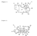
- Figure 1 is a top view of the vicinity of the front end part of the engine with the cylinder head cover removed and without the air intake/exhaust valves or spark plugs
- Figure 2 shows the same assembly as in Figure 1 from which the cam cap and chain guide have also been excluded, providing a cross-sectional view of the variable valve timing device and the camshafts along the upper surface of the cylinder head.
- a cylindrical aperture 2 for spark plug mounting is formed at the center of every combustion chamber ceiling plate part of each cylinder, and two cylindrical apertures 3 for air intake valve mounting and two cylindrical apertures 4 for exhaust valve mounting are formed on both sides thereof.
- An air intake camshaft 5 for driving the air intake valves is disposed above each of the apertures 3, 3 formed in cylinder head 1 for mounting the air intake valves, and an exhaust camshaft 6 for driving the exhaust valves is disposed above each of the apertures 4, 4 for mounting the exhaust valves; these camshafts are disposed parallel to each other, with a gap between them, and parallel with the cylinder layout orientation (i.e. the crankshaft axial direction), but vertical to the axis of the cylinders.
- camshaft supporting parts 7, 7 - which are formed at the upper surface of the lower half of the journal bearing part - are both integrally formed as a part of cylinder head 1 at both sides of the apertures 2 for spark plug mounting in each cylinder, i.e. between the apertures 3, 3 for mounting the air intake valves and between the apertures 4, 4 for exhaust valve mounting, respectively as shown in Figure 2.
- Each cam cap 8, 8 is integrally linked to each camshaft supporting part 7, 7 on both sides of aperture 2 for spark plug mounting as shown in Figure 1 by screwing a bolt that passes through cam cap 8 into a screw hole formed in camshaft supporting part 7, and each camshaft 5, 6 is supported with rotational freedom by supporting it with the lower half of a journal bearing formed in the upper surface of camshaft supporting part 7 and with the upper half of a journal bearing formed in the lower surface of cam cap 8.
- the front end part of exhaust camshaft 6 is supported with rotational freedom by a camshaft supporting part 9 integrally formed at the front end part of cylinder head 1 and by a cam cap 10 connected above it, and a cam sprocket 11 is integrally fixed to the front end of exhaust camshaft 6 by a bolt 12.
- the front end part of air inlet camshaft 5 is held with rotational freedom by a camshaft supporting part 13 integrally linked to the front end part of cylinder head 1 and by a cam cap 14 connected above it, and a variable valve timing device 20 with a cam sprocket 15 formed around its outside is integrally attached to the front end of air inlet camshaft 5 by a bolt 16.
- An endless cam chain 17 is wrapped around the cam sprocket 15 formed around the outside of variable valve timing device 20 and the cam sprocket 11 fixed to the front end part of exhaust cam 6, and this chain also extends around a drive sprocket (not illustrated); as cam chain 17 is driven around by the crankshaft rotation via the drive sprocket, the air intake camshaft 5 and exhaust camshaft 6 are rotationally driven via variable valve timing device 20 and cam sprocket 11 respectively, and the engine's air intake valves and exhaust valves are opened and closed at prescribed timings according to the rotational driving of camshafts 5 and 6.
- FIG. 6 shows, the region above cylinder head 1, including the region occupied by variable valve timing device 20, is covered by a cylinder-head cover 18, and below cylinder-head cover 18 the front side of the engine where cam chain 17 is fitted is also covered by a chain cover 19 extending over a region from cylinder head 1 to the cylinder block (not illustrated).
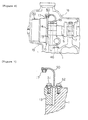
- variable valve timing device 20 attached to the front end part of air intake camshaft 5 is of a hitherto known construction, and as shown in Figure 2, the cover member 21 and boss member 22 of said device 20 are integrally fixed to the front end of air intake camshaft 5 with a bolt 16, and a housing member 23 is provided so as to be capable of relative rotational motion with respect to boss member 22, cam sprocket 15 being integrally formed around the outside of this housing member 23.
- a piston member 24 that surrounds boss member 22 is provided so as to be able to move along the axial direction of camshaft 5 while remaining spline-fitted to the outer surface of boss member 22 and engaged by a helical gear with the inner surface of housing member 23, and piston member 24 - which can thus slide relative to boss member 22 without rotating, and which moves in a spiral fashion relative to housing member 23 - is pressed toward cover member 21 by a coil spring 25 provided between it and boss member 22.
- the hollow part inside housing member 23 is sectioned into two oil chambers 26, 27 by piston member 24, with an oil passage 28 which passes through boss member 22 from air intake camshaft 5 connecting with one oil chamber 26, and an oil passage 29 which passes through boss member 22 from air intake camshaft 5 connecting with the other oil chamber 27; an oil control valve 30, which is described below, sends oil into either one of these oil passages 28, 29 and sends oil out from the other.
- piston member 24 is slid along boss member 22 as oil is supplied by oil passages 28, 29 to one of the oil chambers 26, 27 and discharged from the other, causing piston member 24 to move in the axial direction of camshaft 5 and thereby turning housing member 23 so that housing member 23 is turned relative to boss member 22.
- camshaft supporting part 9 - which supports the front end part of exhaust camshaft 6 to which a simple cam sprocket 11 is fixed - is integrally formed as a part of cylinder head 1
- camshaft supporting part 13 - which supports the front end part of air intake camshaft 5 to which variable valve timing device 20 is fitted - is formed as a cam carrier, which is a separate member to cylinder head 1, and is integrally linked to cylinder head 1.
- Figure 3 and Figure 4 show the configuration of the camshaft supporting part 13, i.e. cam carrier 13, which supports the front end part of air intake camshaft 5 to which the variable valve timing device 20 is fitted;
- Figure 3 is a front view, and
- Figure 4 is a top view.
- Cam carrier 13 which constitutes the camshaft supporting part of air intake camshaft 5, is formed by a journal bearing part (lower half) 31 which supports the front end journal part of air intake camshaft 5, and - below that - a valve attachment part 32 for attaching the valve parts of oil control valve 30; cam carrier 13 is also formed with a pinhole 33 for locating it against cylinder head 1, and with pinholes 34, 34 for locating cam carrier 13 against cam cap 14, and bolt through-holes 35, 35 are also formed to link cam carrier 13 to cylinder head 1 while also securing cam cap 14.
- journal bearing part 31 which connects with the oil passage 28 of air inlet camshaft 5 via an annular slot 36 formed in journal bearing part 31
- an oil passage 39 which connects with the oil passage 29 of air inlet camshaft 5 via an annular slot 38 formed in journal bearing part 31
- an oil passage 40 for supplying lubricating oil to journal bearing part 31 are respectively formed between journal bearing part 31 and valve attachment part 32.
- bolt hole 41 which is used to attach the chain guide is formed at the upper surface of cam carrier 13 so that chain guide 50 - which guides cam chain 17 in the state shown in Figure 1 and Figure 7 - is attached extending from the upper surface of cam carrier 13 to the upper surface of cylinder head 1.
- Figure 5 is a front view showing how each part is connected together
- Figure 6 is a side view showing how each part is connected together
- Figure 7 is a cross section along line A-A in Figure 1 showing how the cam carrier and chain guide are linked
- Figure 8 is a front view showing the arrangement of the oil control valves, the oil filter, and each oil passage.
- camshaft supporting part 9 which supports the front end part of exhaust camshaft 6 to which cam sprocket 11 is fixed, is integrally formed as a part of cylinder head 1
- cam carrier 13 which supports the front end part of air intake camshaft 5 which is fitted with variable valve timing device 20, is formed as a separate member from cylinder head 1, and when it is located on cylinder head 1 by a pin inserted into pin hole 33 and used to locate cam cap 14 by pins inserted into pin holes 34, 34, it is secured together with cam cap 14 by bolts 45 passing through bolt through-holes 35, 35, thereby integrally linking it to cylinder head 1.
- cam carrier 13 which is linked to cylinder head 1 in this way, is disposed so that in plan view it overlaps the cylinder-head bolts 46 for linking cylinder head 1 to the cylinder block (not illustrated), and after cylinder-head bolts 46 have been secured to link cylinder head 1 to the cylinder block, it is fastened together with cam cap 14 by bolts 45 and linked to cylinder head 1.
- chain guide 50 which guides cam chain 17 is fixed by bolts 51 and 52 at its attachment base part so as to connect the upper surface of cam carrier 13 and the upper surface of cylinder head 1 to cam carrier 13 which is linked by bolt 45 to cylinder head 1 as shown in Figure 1 and Figure 7, whereby the link between cam carrier 13 and cylinder head 1 is reinforced so that cam carrier 13 does not lean forward.
- valve part of oil control valve 30 of variable valve timing device 20 is attached to valve attachment part 32 of cam carrier 13 as shown in Figure 8 by passing it through the wall part of cylinder head 1 so that parts of the main body for operating the valve parts according to signals from the ECU are exposed at the exterior of cylinder head 1, in which state it is fixed to cylinder head 1 by a bolt 54, and the inserted part of oil control valve 30 is sealed by an ordinary O-ring member 55 in the wall part of cylinder head 1.
- Oil filter 56 which filters the oil supplied to said oil control valve 30, is attached to the oil control valve 30 fitted in the above manner so that it is partially exposed at the exterior of cylinder head 1 at a part below cam carrier 13 of cylinder head 1, and the oil supplied from the cylinder block is supplied to oil control valve 30 through oil filter 56.
- the cylinder-head bolt 46 that links the cylinder head to the cylinder block can be tightly secured without affecting cam carrier 13 to which the oil control valve 30 of variable valve timing device 20 is attached, and it is thus possible to ensure that cylinder-head bolt 46 is able to establish a firm link between cylinder head 1 and the cylinder block.
- cam carrier 13 as a separate member to cylinder head 1 and disposing it so as to overlap the attachment position of cylinder-head bolt 46 in plan view, the distance between cylinder-head bolt 46 and variable valve timing device 20 does not increase, even when cam carrier 13 is made wider through the attachment of oil control valve 30 to cam carrier 13, and thus there is no increase in the overall front-to-back length of the engine.
- oil control valve 30 can be serviced easily without removing head cover 18, and furthermore, the insertion part of oil control valve 30 can easily be sealed with an ordinary O-ring member 55 so there is no need for a special seal component.
- oil control valve 30 attached to cam carrier 13 is also fixed to cylinder head 1, oil control valve 30 does not vibrate relative to the cam carrier 13 fixed to cylinder head 1.
- oil control filter 56 - which filters the oil supplied to oil control valve 30 - is attached to cylinder head 1 in such a way that it is partially exposed at the outside thereof, so that oil filter 56 can also be serviced easily.
- the present invention is not limited to the above embodiment and can also be applied to engines with different numbers of intake and exhaust valves per cylinder, for example, or to engines where a variable valve timing device is fitted to the exhaust camshaft instead of the air intake camshaft, or to engines where variable valve timing devices are fitted to both the air intake and exhaust camshafts, as e.g. shown in Fig. 9.
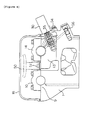
- Figure 9 is a top view of a five-valve engine having 3 air intake valves and 2 exhaust valves, wherein variable valve timing devices are fitted both to the air intake camshaft and the exhaust camshaft respectively, showing the vicinity of the front end part of the engine with the cover taken off and parts such as the air intake and exhaust valves, spark plugs, cam caps and chain guide removed, and
- Figure 10 is a side view showing the central axes of the oil control valves 30 and each of the air intake valves on the air intake side of the engine shown in Figure 9.
- one cam carrier 13 which supports the front end parts of both air intake camshaft 5 and exhaust camshaft 6 is formed as a separate member from cylinder head 1, and is connected to the front end part of cylinder head 1, and oil control valves 30 are attached to this cam carrier 13 on the air intake and exhaust sides respectively.
- the axes B1 and B3 of the air intake valves on either side are inclined as shown in Figure 10 so as to converge toward the axis B2 of the central air intake valve at a point below the valves, and the axis C of oil control valve 30 on the air intake side is inclined so that it diverges from the axis B1 of the neighboring air intake valve toward the bottom thereof, so that any increase in the overall front-to-back length of the engine can be kept as small as possible without having the oil control valve 30 interfere with the lifter retaining part of cylinder head 1, and without the attachment position of oil control valve 30 coming too close to the chain chamber in the wall part of cylinder head 1.
- the axis C of the oil control valve 30 is inclined with respect to a plane vertical to the axis of the camshafts 5, 6 to the rear end of the engine (away from the valve timing device 20) in its course from the inner and lower end of the oil control valve 30 to the exterior upper end thereof, as shown in Fig. 10.
- the axis C of the oil control valve 30 may be inclined, as e.g. shown in Fig. 5, in a way that it rises upwards to the engine top from the center of the engine to the outside of the engine.
- the axis C is inclined in two directions with respect to the main engine construction planes or axes.
- the incline of two opposite axes C located on the intake and exhaust side of the engine may be symmetrical to a vertical center plane set centered between the intake and exhaust camshafts or a plane laid through all cylinder axes.
- variable valve timing device With a four-stroke engine equipped with a variable valve timing device according to the present invention as described above, it is possible to attach an oil control valve to the camshaft supporting part of the camshaft to which the variable valve timing device is fitted without increasing the overall length of the engine or compromising the fastening of the cylinder-head bolts, and it is possible to ensure that the oil control valve can be easily serviced by exposing the oil control valve on the outside of the engine while keeping it firmly held in place.
Landscapes
- Engineering & Computer Science (AREA)
- Mechanical Engineering (AREA)
- General Engineering & Computer Science (AREA)
- Valve Device For Special Equipments (AREA)
- Cylinder Crankcases Of Internal Combustion Engines (AREA)
- Valve-Gear Or Valve Arrangements (AREA)
- Output Control And Ontrol Of Special Type Engine (AREA)
Applications Claiming Priority (2)
| Application Number | Priority Date | Filing Date | Title |
|---|---|---|---|
| JP10003398 | 1998-03-27 | ||
| JP10003398A JP4036401B2 (ja) | 1998-03-27 | 1998-03-27 | 可変バルブタイミング装置を備えた4サイクルエンジン |
Publications (3)
| Publication Number | Publication Date |
|---|---|
| EP0945598A2 true EP0945598A2 (de) | 1999-09-29 |
| EP0945598A3 EP0945598A3 (de) | 2000-06-07 |
| EP0945598B1 EP0945598B1 (de) | 2006-12-27 |
Family
ID=14263226
Family Applications (1)
| Application Number | Title | Priority Date | Filing Date |
|---|---|---|---|
| EP99106340A Expired - Lifetime EP0945598B1 (de) | 1998-03-27 | 1999-03-26 | Viertakt-Brennkraftmaschine |
Country Status (4)
| Country | Link |
|---|---|
| US (1) | US6076492A (de) |
| EP (1) | EP0945598B1 (de) |
| JP (1) | JP4036401B2 (de) |
| DE (1) | DE69934533T2 (de) |
Cited By (14)
| Publication number | Priority date | Publication date | Assignee | Title |
|---|---|---|---|---|
| EP1057982A3 (de) * | 1999-05-31 | 2002-08-14 | Yamaha Hatsudoki Kabushiki Kaisha | Viertakt-Brennkraftmaschine |
| EP1081339A3 (de) * | 1999-09-03 | 2002-08-21 | Honda Giken Kogyo Kabushiki Kaisha | Gehäuse für ein Nockenwellen-Riemenantriebssystem in einer Brennkraftmaschine |
| EP1046793A3 (de) * | 1999-04-21 | 2002-08-21 | Ford Global Technologies, Inc. | Variable Ventilsteuerungseinrichtung und Verfahren |
| EP1081340A3 (de) * | 1999-09-03 | 2002-08-21 | Honda Giken Kogyo Kabushiki Kaisha | Ölkanal für eine Ventilantriebsvorrichtung in einer Brennkraftmaschine |
| EP1249582A2 (de) * | 2001-04-11 | 2002-10-16 | INA- Schaeffler KG | Brennkraftmaschine mit zumindest zwei obenliegenden Nockenwellen |
| EP1201884A3 (de) * | 2000-10-25 | 2003-03-12 | Honda Giken Kogyo Kabushiki Kaisha | Ventilsteuerungseinrichtung für eine Brennkraftmaschine |
| EP1340886A1 (de) * | 2000-12-04 | 2003-09-03 | Mitsubishi Denki Kabushiki Kaisha | Regelventil für öl und verfahren zum montieren eines solchen ventils |
| EP1422387A1 (de) * | 2002-11-14 | 2004-05-26 | Mazda Motor Corporation | Variable Ventilsteuervorrichtung einer Brennkraftmaschine |
| WO2006136294A1 (de) * | 2005-06-22 | 2006-12-28 | Gm Global Technology Operations, Inc. | Einrichtung zur hydraulischen ventilhubumschaltung |
| EP1783331A1 (de) * | 2005-11-07 | 2007-05-09 | Ford Global Technologies, LLC, A subsidary of Ford Motor Company | System mit einer Einlaßnockenwelle, einer Auslaßnockenwelle und einem Nockenwellenversteller und Verwendung eines derartigen Systems |
| WO2007054430A1 (de) * | 2005-11-12 | 2007-05-18 | Schaeffler Kg | Verfahren zur variablen ventilsteuerung eines verbrennungsmotors |
| EP1496210A3 (de) * | 2003-06-25 | 2007-11-21 | HONDA MOTOR CO., Ltd. | Aussenbordmotor |
| WO2014071927A1 (de) * | 2012-11-12 | 2014-05-15 | Schaeffler Technologies AG & Co. KG | Nockenwellenverstelleinrichtung |
| EP2881556A1 (de) * | 2013-12-09 | 2015-06-10 | Mitsubishi Jidosha Kogyo Kabushiki Kaisha | Motor |
Families Citing this family (48)
| Publication number | Priority date | Publication date | Assignee | Title |
|---|---|---|---|---|
| JP4229501B2 (ja) * | 1998-11-13 | 2009-02-25 | ヤマハ発動機株式会社 | エンジンのオイルコントロールバルブ配置構造 |
| US6705264B2 (en) | 1998-12-24 | 2004-03-16 | Yamaha Marine Kabushiki Kaisha | Valve control for outboard motor engine |
| JP2001073718A (ja) * | 1999-09-03 | 2001-03-21 | Yamaha Motor Co Ltd | エンジンの動弁装置 |
| US6302751B1 (en) | 1999-09-27 | 2001-10-16 | Yamaha Hatsudoki Kabushiki Kaisha | Engine arrangement for small planing watercraft |
| DE10002512A1 (de) * | 2000-01-21 | 2001-07-26 | Porsche Ag | Zylinderkopf für eine ventilgesteuerte Brennkraftmaschine |
| US6293244B1 (en) * | 2000-05-09 | 2001-09-25 | Ford Global Technologies, Inc. | Oil flow control system for engine cylinder head |
| JP2001342919A (ja) | 2000-05-31 | 2001-12-14 | Sanshin Ind Co Ltd | 船外機用4サイクルエンジン |
| JP2001342812A (ja) | 2000-05-31 | 2001-12-14 | Sanshin Ind Co Ltd | 船外機用4サイクルエンジン |
| US6910450B2 (en) * | 2000-05-31 | 2005-06-28 | Yamaha Marine Kabushiki Kaisha | Variable valve timing structure for outboard motor engine |
| US6672283B2 (en) | 2000-06-09 | 2004-01-06 | Yamaha Marine Kabushiki Kaisha | Four-cycle engine for marine drive |
| JP3411895B2 (ja) * | 2000-09-18 | 2003-06-03 | 本田技研工業株式会社 | エンジンにおけるタイミングチェーン潤滑構造 |
| JP3497462B2 (ja) * | 2000-10-25 | 2004-02-16 | 本田技研工業株式会社 | エンジンの動弁制御装置 |
| GB2369175A (en) * | 2000-11-18 | 2002-05-22 | Mechadyne Plc | Variable phase coupling |
| JP2003003870A (ja) * | 2001-06-21 | 2003-01-08 | Sanshin Ind Co Ltd | 船外機用4サイクルエンジンのバルブタイミング制御装置 |
| JP2003003898A (ja) | 2001-06-22 | 2003-01-08 | Sanshin Ind Co Ltd | 船外機用4サイクルエンジンの制御装置 |
| JP2003013759A (ja) | 2001-06-29 | 2003-01-15 | Sanshin Ind Co Ltd | 船外機用4サイクルエンジンのバルブタイミング制御装置 |
| JP2003013761A (ja) | 2001-07-02 | 2003-01-15 | Sanshin Ind Co Ltd | 船外機用4サイクルエンジンのバルブタイミング制御装置 |
| JP2003013760A (ja) | 2001-07-02 | 2003-01-15 | Sanshin Ind Co Ltd | 船外機用4サイクルエンジンのバルブタイミング制御装置 |
| JP2003020964A (ja) | 2001-07-04 | 2003-01-24 | Sanshin Ind Co Ltd | 船外機用4サイクルエンジンのバルブタイミング制御装置 |
| JP3963084B2 (ja) * | 2001-07-10 | 2007-08-22 | スズキ株式会社 | 船外機用4サイクルエンジン |
| JP2003035179A (ja) | 2001-07-25 | 2003-02-07 | Sanshin Ind Co Ltd | 船外機用4サイクルエンジン |
| JP2003035156A (ja) | 2001-07-25 | 2003-02-07 | Sanshin Ind Co Ltd | 船外機用4サイクルエンジン |
| JP3531146B2 (ja) * | 2001-09-03 | 2004-05-24 | 本田技研工業株式会社 | エンジンの補機の取付構造 |
| JP3668167B2 (ja) * | 2001-09-14 | 2005-07-06 | 本田技研工業株式会社 | 内燃機関のバルブタイミング制御装置 |
| JP3966003B2 (ja) * | 2002-02-05 | 2007-08-29 | 日産自動車株式会社 | 内燃機関 |
| DE10223431B4 (de) * | 2002-05-25 | 2004-07-08 | Ina-Schaeffler Kg | Brennkraftmaschine mit zumindest zwei nebeneinander angeordneten, jeweils mit einer Vorrichtung zur Drehwinkelverstellung gegenüber einer Kurbelwelle ausgebildeten Nockenwellen |
| JP4068410B2 (ja) * | 2002-07-31 | 2008-03-26 | ヤマハマリン株式会社 | 船外機用エンジン |
| DE10307624A1 (de) * | 2003-02-22 | 2004-09-02 | Daimlerchrysler Ag | Vorrichtung zur relativen Drehwinkeländerung einer Nockenwelle zu einem Antriebsrad einer Brennkraftmaschine |
| KR20040091790A (ko) * | 2003-04-22 | 2004-11-02 | 현대자동차주식회사 | 가변 밸브 타이밍 장치가 적용되는 실린더 헤드의 캠샤프트 윤활 구조 |
| EP1596040B1 (de) * | 2004-05-14 | 2010-10-13 | Schaeffler KG | Nockenwellenversteller |
| JP4137019B2 (ja) * | 2004-07-05 | 2008-08-20 | トヨタ自動車株式会社 | 樹脂製シリンダヘッドカバー |
| JP4118262B2 (ja) * | 2004-07-14 | 2008-07-16 | トヨタ自動車株式会社 | バルブケース及び樹脂製シリンダヘッドカバー |
| KR20060015005A (ko) * | 2004-08-13 | 2006-02-16 | 현대자동차주식회사 | 엔진의 연속가변밸브타이밍장치용 오일필터 |
| DE102004049028B4 (de) * | 2004-10-08 | 2011-03-10 | Audi Ag | Hydraulische Nockenwellenverstelleinrichtung |
| JP4616229B2 (ja) * | 2006-09-29 | 2011-01-19 | 本田技研工業株式会社 | 多気筒内燃機関 |
| JP4983568B2 (ja) * | 2007-11-27 | 2012-07-25 | トヨタ自動車株式会社 | カムキャリアおよびその製造方法 |
| US7841311B2 (en) * | 2008-01-04 | 2010-11-30 | Hilite International Inc. | Variable valve timing device |
| DE102008033230B4 (de) | 2008-01-04 | 2010-05-27 | Hydraulik-Ring Gmbh | Doppelter Nockenwellenversteller in Schichtaufbau |
| EP2112336B1 (de) | 2008-04-24 | 2012-08-08 | Ford Global Technologies, LLC | Gemeinsame Ölversorgung des VCT und der Nockenwellenlager über eine hohle Nockenwelle |
| DE102008023098A1 (de) | 2008-05-09 | 2009-12-17 | Hydraulik-Ring Gmbh | Doppelter Nockenwellenversteller in Schichtaufbau |
| US8171903B2 (en) * | 2008-12-03 | 2012-05-08 | Hyundai Motor Company | Intermediate lock pin type variable valve timing unit for vehicle and continuously variable valve timing device using the same |
| JP2011127432A (ja) * | 2009-12-15 | 2011-06-30 | Hitachi Automotive Systems Ltd | バルブタイミング制御装置用カバー及びその製造方法 |
| DE102010033296A1 (de) | 2010-08-04 | 2012-02-09 | Hydraulik-Ring Gmbh | Nockenwellenversteller, insbesondere mit Nockenwelle |
| JP5825829B2 (ja) * | 2011-04-20 | 2015-12-02 | 本田技研工業株式会社 | 内燃機関のカムシャフト支持構造 |
| JP6237475B2 (ja) * | 2014-05-30 | 2017-11-29 | トヨタ自動車株式会社 | 筒内直接噴射式内燃機関及び筒内直接噴射式内燃機関の制御装置 |
| FR3060645B1 (fr) * | 2016-12-19 | 2018-11-30 | Renault S.A.S. | Arbre a cames comportant un systeme de dephasage |
| DE102017118862A1 (de) * | 2017-08-18 | 2019-02-21 | Man Truck & Bus Ag | Vorrichtung zum drehbaren Lagern einer Nockenwelle |
| JP7160505B2 (ja) * | 2018-03-30 | 2022-10-25 | ダイハツ工業株式会社 | 内燃機関 |
Family Cites Families (23)
| Publication number | Priority date | Publication date | Assignee | Title |
|---|---|---|---|---|
| DE58901050D1 (de) * | 1988-07-15 | 1992-04-30 | Audi Ag | Antriebsvorrichtung fuer eine nockenwelle einer brennkraftmaschine. |
| JPH0727365Y2 (ja) * | 1988-08-18 | 1995-06-21 | 株式会社ユニシアジェックス | 内燃機関のバルブタイミング制御装置 |
| DE3929621A1 (de) * | 1989-09-06 | 1991-03-07 | Bayerische Motoren Werke Ag | Vorrichtung zur relativen drehwinkelverstellung einer welle zu einem antriebsrad, insbesondere nockenwelle einer brennkraftmaschine |
| US5058539A (en) * | 1989-09-20 | 1991-10-22 | Atsugi Unisia Corporation | Valve timing adjusting system for internal combustion engine |
| JPH03107511A (ja) * | 1989-09-21 | 1991-05-07 | Yamaha Motor Co Ltd | バルブタイミング遅角装置 |
| JP2741266B2 (ja) * | 1989-12-18 | 1998-04-15 | マツダ株式会社 | エンジンの吸排気制御装置 |
| US5143034A (en) * | 1990-03-29 | 1992-09-01 | Mazda Motor Corporation | Lubrication system for V-type overhead camshaft engine |
| JPH0482343U (de) * | 1990-11-29 | 1992-07-17 | ||
| DE4135377A1 (de) * | 1991-10-26 | 1993-04-29 | Bosch Gmbh Robert | Hydraulische steuereinrichtung |
| DE4218078C5 (de) * | 1992-06-01 | 2006-07-13 | Schaeffler Kg | Vorrichtung zur selbsttätigen, kontinuierlichen Winkelverstellung zwischen zwei in Antriebsverbindung stehenden Wellen |
| JPH0610626A (ja) * | 1992-06-26 | 1994-01-18 | Nippondenso Co Ltd | 内燃機関のバルブタイミング制御装置 |
| JP2891013B2 (ja) * | 1993-01-18 | 1999-05-17 | 日産自動車株式会社 | V型内燃機関における可変バルブタイミングコントロール装置 |
| DE4324791A1 (de) * | 1993-07-23 | 1995-01-26 | Porsche Ag | Zylinderkopfanordnung einer Brennkraftmaschine |
| JP3374475B2 (ja) * | 1993-11-16 | 2003-02-04 | 株式会社デンソー | バルブタイミング調整装置 |
| DE4429071C2 (de) * | 1994-08-17 | 1997-07-31 | Porsche Ag | Vorrichtung zum Spannen und Verstellen eines als Kette ausgebildeten Umschlingungstriebes |
| JPH0874541A (ja) * | 1994-08-31 | 1996-03-19 | Yamaha Motor Co Ltd | 4サイクルエンジン |
| US5718196A (en) * | 1994-09-30 | 1998-02-17 | Yamaha Hatsudoki Kabushiki Kaisha | Lubrication and camshaft control system for engine |
| DE19502496C2 (de) * | 1995-01-27 | 1998-09-24 | Schaeffler Waelzlager Ohg | Vorrichtung zum Verändern der Steuerzeiten einer Brennkraftmaschine |
| US5829399A (en) * | 1995-12-15 | 1998-11-03 | Ina Walzlager Schaeffler Ohg | Pressure fluid supply system for a variable camshaft adjustment |
| JP3189679B2 (ja) * | 1996-05-24 | 2001-07-16 | トヨタ自動車株式会社 | 内燃機関のバルブ特性制御装置 |
| US5713319A (en) * | 1996-07-12 | 1998-02-03 | Carraro S.P.A. | Phase variator |
| JPH1089024A (ja) * | 1996-09-13 | 1998-04-07 | Toyota Motor Corp | 内燃機関のバルブ特性可変機構 |
| JP3834890B2 (ja) * | 1996-10-15 | 2006-10-18 | トヨタ自動車株式会社 | 内燃機関のバルブ特性制御装置 |
-
1998
- 1998-03-27 JP JP10003398A patent/JP4036401B2/ja not_active Expired - Fee Related
-
1999
- 1999-03-26 DE DE69934533T patent/DE69934533T2/de not_active Expired - Lifetime
- 1999-03-26 EP EP99106340A patent/EP0945598B1/de not_active Expired - Lifetime
- 1999-03-26 US US09/277,663 patent/US6076492A/en not_active Expired - Lifetime
Non-Patent Citations (1)
| Title |
|---|
| None |
Cited By (22)
| Publication number | Priority date | Publication date | Assignee | Title |
|---|---|---|---|---|
| EP1046793A3 (de) * | 1999-04-21 | 2002-08-21 | Ford Global Technologies, Inc. | Variable Ventilsteuerungseinrichtung und Verfahren |
| EP1057982A3 (de) * | 1999-05-31 | 2002-08-14 | Yamaha Hatsudoki Kabushiki Kaisha | Viertakt-Brennkraftmaschine |
| EP1081339A3 (de) * | 1999-09-03 | 2002-08-21 | Honda Giken Kogyo Kabushiki Kaisha | Gehäuse für ein Nockenwellen-Riemenantriebssystem in einer Brennkraftmaschine |
| EP1081340A3 (de) * | 1999-09-03 | 2002-08-21 | Honda Giken Kogyo Kabushiki Kaisha | Ölkanal für eine Ventilantriebsvorrichtung in einer Brennkraftmaschine |
| EP1201884A3 (de) * | 2000-10-25 | 2003-03-12 | Honda Giken Kogyo Kabushiki Kaisha | Ventilsteuerungseinrichtung für eine Brennkraftmaschine |
| US6619247B2 (en) | 2000-10-25 | 2003-09-16 | Honda Giken Kogyo Kabushiki Kaisha | Valve operating control system for engine |
| EP1340886A4 (de) * | 2000-12-04 | 2005-06-22 | Mitsubishi Electric Corp | Regelventil für öl und verfahren zum montieren eines solchen ventils |
| EP1340886A1 (de) * | 2000-12-04 | 2003-09-03 | Mitsubishi Denki Kabushiki Kaisha | Regelventil für öl und verfahren zum montieren eines solchen ventils |
| EP1249582A2 (de) * | 2001-04-11 | 2002-10-16 | INA- Schaeffler KG | Brennkraftmaschine mit zumindest zwei obenliegenden Nockenwellen |
| EP1249582A3 (de) * | 2001-04-11 | 2003-01-08 | INA- Schaeffler KG | Brennkraftmaschine mit zumindest zwei obenliegenden Nockenwellen |
| DE10118119C2 (de) * | 2001-04-11 | 2003-11-20 | Ina Schaeffler Kg | Brennkraftmaschine mit zwei in deren Zylinderkopf nebeneinander angeordneten Nockenwellen, insbesondere mit einer Einlass- und einer Auslassnockenwelle |
| EP1422387A1 (de) * | 2002-11-14 | 2004-05-26 | Mazda Motor Corporation | Variable Ventilsteuervorrichtung einer Brennkraftmaschine |
| US6860247B2 (en) | 2002-11-14 | 2005-03-01 | Mazda Motor Corporation | Engine variable valve timing system |
| EP1496210A3 (de) * | 2003-06-25 | 2007-11-21 | HONDA MOTOR CO., Ltd. | Aussenbordmotor |
| WO2006136294A1 (de) * | 2005-06-22 | 2006-12-28 | Gm Global Technology Operations, Inc. | Einrichtung zur hydraulischen ventilhubumschaltung |
| DE102005028805A1 (de) * | 2005-06-22 | 2007-01-04 | GM Global Technology Operations, Inc., Detroit | Einrichtung zur hydraulischen Ventilhubumschaltung |
| EP1783331A1 (de) * | 2005-11-07 | 2007-05-09 | Ford Global Technologies, LLC, A subsidary of Ford Motor Company | System mit einer Einlaßnockenwelle, einer Auslaßnockenwelle und einem Nockenwellenversteller und Verwendung eines derartigen Systems |
| WO2007054430A1 (de) * | 2005-11-12 | 2007-05-18 | Schaeffler Kg | Verfahren zur variablen ventilsteuerung eines verbrennungsmotors |
| US7874272B2 (en) | 2005-11-12 | 2011-01-25 | Schaeffler Kg | Method of variable valve timing in an internal combustion engine |
| WO2014071927A1 (de) * | 2012-11-12 | 2014-05-15 | Schaeffler Technologies AG & Co. KG | Nockenwellenverstelleinrichtung |
| EP2881556A1 (de) * | 2013-12-09 | 2015-06-10 | Mitsubishi Jidosha Kogyo Kabushiki Kaisha | Motor |
| US9562446B2 (en) | 2013-12-09 | 2017-02-07 | Mitsubishi Jidosha Kogyo Kabushiki Kaisha | Engine |
Also Published As
| Publication number | Publication date |
|---|---|
| EP0945598B1 (de) | 2006-12-27 |
| EP0945598A3 (de) | 2000-06-07 |
| DE69934533D1 (de) | 2007-02-08 |
| JPH11280541A (ja) | 1999-10-12 |
| JP4036401B2 (ja) | 2008-01-23 |
| DE69934533T2 (de) | 2007-07-26 |
| US6076492A (en) | 2000-06-20 |
Similar Documents
| Publication | Publication Date | Title |
|---|---|---|
| EP0945598B1 (de) | Viertakt-Brennkraftmaschine | |
| EP1156191B1 (de) | Brennkraftmaschine mit Nockenwellewinkelsensoreinrichtung | |
| EP1134402B1 (de) | Zylinderkopf | |
| EP1522694B1 (de) | Zylinderkopf für eine Brennkraftmaschine mit Nockenwellenpositionssensor | |
| CA2317159C (en) | Construction for a cam rotation sensor attaching portion | |
| JPS60243306A (ja) | 内燃機関のシリンダヘツド組立体構造 | |
| US4970999A (en) | Cylinder head for overhead camshaft engine | |
| EP1243780A2 (de) | Brennkraftmaschine | |
| EP0357511B1 (de) | Brennkraftmaschine mit zwei obenliegenden Nockenwellen | |
| EP1384859B1 (de) | Brennkraftmaschine | |
| EP1403497B1 (de) | Nockenwellenlagerstruktur für eine Brennkraftmaschine mit oben liegenden Nockenwellen | |
| JP4036402B2 (ja) | 4サイクルエンジンのシリンダヘッド構造 | |
| JP3272245B2 (ja) | 4サイクルエンジンのチェーンカバー構造 | |
| JP3327322B2 (ja) | バルブタイミング可変装置を備えた4サイクルエンジン | |
| EP1243760A2 (de) | Brennkraftmaschine | |
| JP3591744B2 (ja) | Dohc型エンジンのカムキャップ構造 | |
| EP0691457B1 (de) | Brennkraftmaschine | |
| KR200167146Y1 (ko) | 캠샤프트의 밸브 타이밍 조절장치 | |
| JPS59180017A (ja) | 頭上弁式内燃機関のカム軸受構造 | |
| JP3117765B2 (ja) | 5バルブエンジンの動弁装置 | |
| JPH03117603A (ja) | エンジンの動弁装置 | |
| JP3156789B2 (ja) | V型5バルブエンジンの動弁装置 | |
| JP2958722B2 (ja) | 内燃機関のシリンダヘッドカバー構造 | |
| JPH0413422Y2 (de) | ||
| JP3079836B2 (ja) | 内燃機関の潤滑構造 |
Legal Events
| Date | Code | Title | Description |
|---|---|---|---|
| PUAI | Public reference made under article 153(3) epc to a published international application that has entered the european phase |
Free format text: ORIGINAL CODE: 0009012 |
|
| AK | Designated contracting states |
Kind code of ref document: A2 Designated state(s): DE FR GB IT |
|
| AX | Request for extension of the european patent |
Free format text: AL;LT;LV;MK;RO;SI |
|
| PUAL | Search report despatched |
Free format text: ORIGINAL CODE: 0009013 |
|
| AK | Designated contracting states |
Kind code of ref document: A3 Designated state(s): AT BE CH CY DE DK ES FI FR GB GR IE IT LI LU MC NL PT SE |
|
| AX | Request for extension of the european patent |
Free format text: AL;LT;LV;MK;RO;SI |
|
| RIC1 | Information provided on ipc code assigned before grant |
Free format text: 7F 01L 1/344 A, 7F 01L 1/26 B, 7F 01L 1/053 B, 7F 01L 1/02 B, 7F 01L 1/46 B, 7F 01L 1/34 B |
|
| 17P | Request for examination filed |
Effective date: 20001201 |
|
| AKX | Designation fees paid |
Free format text: DE FR GB IT |
|
| 17Q | First examination report despatched |
Effective date: 20031013 |
|
| GRAP | Despatch of communication of intention to grant a patent |
Free format text: ORIGINAL CODE: EPIDOSNIGR1 |
|
| GRAS | Grant fee paid |
Free format text: ORIGINAL CODE: EPIDOSNIGR3 |
|
| GRAA | (expected) grant |
Free format text: ORIGINAL CODE: 0009210 |
|
| AK | Designated contracting states |
Kind code of ref document: B1 Designated state(s): DE FR GB IT |
|
| PG25 | Lapsed in a contracting state [announced via postgrant information from national office to epo] |
Ref country code: IT Free format text: LAPSE BECAUSE OF FAILURE TO SUBMIT A TRANSLATION OF THE DESCRIPTION OR TO PAY THE FEE WITHIN THE PRESCRIBED TIME-LIMIT;WARNING: LAPSES OF ITALIAN PATENTS WITH EFFECTIVE DATE BEFORE 2007 MAY HAVE OCCURRED AT ANY TIME BEFORE 2007. THE CORRECT EFFECTIVE DATE MAY BE DIFFERENT FROM THE ONE RECORDED. Effective date: 20061227 |
|
| REG | Reference to a national code |
Ref country code: GB Ref legal event code: FG4D |
|
| REF | Corresponds to: |
Ref document number: 69934533 Country of ref document: DE Date of ref document: 20070208 Kind code of ref document: P |
|
| EN | Fr: translation not filed | ||
| PLBE | No opposition filed within time limit |
Free format text: ORIGINAL CODE: 0009261 |
|
| STAA | Information on the status of an ep patent application or granted ep patent |
Free format text: STATUS: NO OPPOSITION FILED WITHIN TIME LIMIT |
|
| GBPC | Gb: european patent ceased through non-payment of renewal fee |
Effective date: 20070327 |
|
| 26N | No opposition filed |
Effective date: 20070928 |
|
| PG25 | Lapsed in a contracting state [announced via postgrant information from national office to epo] |
Ref country code: GB Free format text: LAPSE BECAUSE OF NON-PAYMENT OF DUE FEES Effective date: 20070327 Ref country code: FR Free format text: LAPSE BECAUSE OF FAILURE TO SUBMIT A TRANSLATION OF THE DESCRIPTION OR TO PAY THE FEE WITHIN THE PRESCRIBED TIME-LIMIT Effective date: 20070817 |
|
| PG25 | Lapsed in a contracting state [announced via postgrant information from national office to epo] |
Ref country code: FR Free format text: LAPSE BECAUSE OF FAILURE TO SUBMIT A TRANSLATION OF THE DESCRIPTION OR TO PAY THE FEE WITHIN THE PRESCRIBED TIME-LIMIT Effective date: 20061227 |
|
| PGFP | Annual fee paid to national office [announced via postgrant information from national office to epo] |
Ref country code: DE Payment date: 20180322 Year of fee payment: 20 |
|
| REG | Reference to a national code |
Ref country code: DE Ref legal event code: R071 Ref document number: 69934533 Country of ref document: DE |