EP1243780A2 - Brennkraftmaschine - Google Patents
Brennkraftmaschine Download PDFInfo
- Publication number
- EP1243780A2 EP1243780A2 EP02006406A EP02006406A EP1243780A2 EP 1243780 A2 EP1243780 A2 EP 1243780A2 EP 02006406 A EP02006406 A EP 02006406A EP 02006406 A EP02006406 A EP 02006406A EP 1243780 A2 EP1243780 A2 EP 1243780A2
- Authority
- EP
- European Patent Office
- Prior art keywords
- pipe
- plug
- head cover
- internal combustion
- hole
- Prior art date
- Legal status (The legal status is an assumption and is not a legal conclusion. Google has not performed a legal analysis and makes no representation as to the accuracy of the status listed.)
- Withdrawn
Links
Images


Classifications
-
- F—MECHANICAL ENGINEERING; LIGHTING; HEATING; WEAPONS; BLASTING
- F02—COMBUSTION ENGINES; HOT-GAS OR COMBUSTION-PRODUCT ENGINE PLANTS
- F02F—CYLINDERS, PISTONS OR CASINGS, FOR COMBUSTION ENGINES; ARRANGEMENTS OF SEALINGS IN COMBUSTION ENGINES
- F02F1/00—Cylinders; Cylinder heads
- F02F1/24—Cylinder heads
- F02F1/242—Arrangement of spark plugs or injectors
-
- F—MECHANICAL ENGINEERING; LIGHTING; HEATING; WEAPONS; BLASTING
- F02—COMBUSTION ENGINES; HOT-GAS OR COMBUSTION-PRODUCT ENGINE PLANTS
- F02F—CYLINDERS, PISTONS OR CASINGS, FOR COMBUSTION ENGINES; ARRANGEMENTS OF SEALINGS IN COMBUSTION ENGINES
- F02F1/00—Cylinders; Cylinder heads
- F02F1/24—Cylinder heads
- F02F1/42—Shape or arrangement of intake or exhaust channels in cylinder heads
- F02F1/4214—Shape or arrangement of intake or exhaust channels in cylinder heads specially adapted for four or more valves per cylinder
-
- F—MECHANICAL ENGINEERING; LIGHTING; HEATING; WEAPONS; BLASTING
- F02—COMBUSTION ENGINES; HOT-GAS OR COMBUSTION-PRODUCT ENGINE PLANTS
- F02B—INTERNAL-COMBUSTION PISTON ENGINES; COMBUSTION ENGINES IN GENERAL
- F02B75/00—Other engines
- F02B75/16—Engines characterised by number of cylinders, e.g. single-cylinder engines
- F02B75/18—Multi-cylinder engines
- F02B2075/1804—Number of cylinders
- F02B2075/1832—Number of cylinders eight
-
- F—MECHANICAL ENGINEERING; LIGHTING; HEATING; WEAPONS; BLASTING
- F02—COMBUSTION ENGINES; HOT-GAS OR COMBUSTION-PRODUCT ENGINE PLANTS
- F02B—INTERNAL-COMBUSTION PISTON ENGINES; COMBUSTION ENGINES IN GENERAL
- F02B2275/00—Other engines, components or details, not provided for in other groups of this subclass
- F02B2275/18—DOHC [Double overhead camshaft]
-
- F—MECHANICAL ENGINEERING; LIGHTING; HEATING; WEAPONS; BLASTING
- F02—COMBUSTION ENGINES; HOT-GAS OR COMBUSTION-PRODUCT ENGINE PLANTS
- F02B—INTERNAL-COMBUSTION PISTON ENGINES; COMBUSTION ENGINES IN GENERAL
- F02B75/00—Other engines
- F02B75/16—Engines characterised by number of cylinders, e.g. single-cylinder engines
- F02B75/18—Multi-cylinder engines
- F02B75/22—Multi-cylinder engines with cylinders in V, fan, or star arrangement
-
- F—MECHANICAL ENGINEERING; LIGHTING; HEATING; WEAPONS; BLASTING
- F02—COMBUSTION ENGINES; HOT-GAS OR COMBUSTION-PRODUCT ENGINE PLANTS
- F02F—CYLINDERS, PISTONS OR CASINGS, FOR COMBUSTION ENGINES; ARRANGEMENTS OF SEALINGS IN COMBUSTION ENGINES
- F02F1/00—Cylinders; Cylinder heads
- F02F1/24—Cylinder heads
- F02F2001/244—Arrangement of valve stems in cylinder heads
- F02F2001/245—Arrangement of valve stems in cylinder heads the valve stems being orientated at an angle with the cylinder axis
Definitions
- the present invention relates to an internal combustion engine according to the preamble portion of claim 1.
- FIG. 11 A conventional example of such a structure for attaching the plug pipe is shown in FIG. 11: A plug thread hole 81 a is bored in a cylinder head 81 into which an ignition plug 82 is screwed, a plug pipe attaching hole 81b is bored to be continuous from the thread hole 81a and of a greater diameter than that of the thread hole 81a, a pipe inserting hole 83a is bored in part of a head cover 83 opposite the plug pipe attaching hole 81b, and a plug pipe 84 is passed through the pipe inserting hole 83a and press fitted into the plug pipe attaching hole 81b.
- a sealing material 85 is placed on the inside round surface of the pipe inserting hole 83a to seal up the upper end portion of the plug pipe 84.
- a coil member 87 with an ignition coil 86 connected thereto is removably inserted into the plug pipe 84, and is electrically connected to the terminal electrode of an ignition plug 82.
- the plug pipe 84 is secured by press-fitting it into the cylinder head 81.
- the head cover 83 is placed from above, while taking care that the plug pipe 84 passes through the sealing member 85, onto the cylinder head 81, and tightened with bolts.
- the coil member 87 is drawn out of the plug pipe 84, and the ignition plug 82 is removed using a tool inserted into the plug pipe 84.
- the present invention has been made in consideration of the above situation associated with the conventional structure with the objective to provide an internal combustion engine as indicated above allowing to eliminate the time-consuming work when attaching the head cover to the cylinder head and to facilitate the work of checking and replacing the ignition plugs of internal combustion engines.
- an internal combustion engine comprising at least one cylinder having a cylinder head, a combustion chamber, an ignition plug member, in particular a spark plug, and a head cover, said ignition plug member being arranged in a plug thread hole leading into the combustion chamber and being connected to a power supply means via a coil member arranged in a plug pipe, wherein the plug pipe is divided into at least first and second pipe members, and wherein a lower end of the first pipe member is secured to the cylinder head and an upper end of the second pipe member is adapted to be inserted into a pipe insertion hole in the head cover.
- the plug pipe is made up of two parts, the first and second pipe members, wherein the first pipe member is fixed to the cylinder head and the second pipe member can be drawn out through the pipe inserting hole of the head cover. Therefore, when the head cover is to be attached, firstly the first pipe member only is secured to the cylinder head and in that state the head cover is attached and secured. In that case, since the first pipe member remains in the head cover, alignment is unnecessary between the plug pipe and the pipe inserting hole. Then the head cover is attached and the second pipe member is inserted through the pipe supporting hole.
- the lower end of the first pipe member is secured to, in particular press-fitted into, a plug pipe attachment hole of the cylinder head.
- the upper end of the second pipe member passing through the pipe insertion hole in the head cover projects outwardly of the head cover.
- the upper end of the second pipe member is provided with a sealing member in contact with the inside surface of the pipe insertion hole.
- the plug pipe is made up of two parts, a lower pipe (first pipe member) fixed into the plug pipe attaching hole and an upper pipe (second pipe member) that can be drawn out through the pipe inserting hole of the head cover, and the gap between the pipe inserting hole and the upper pipe is sealed up with the sealing member attached to the upper pipe. Therefore, when the head cover is to be attached, first the lower pipe only is secured to the cylinder head and in that state the head cover is attached and secured. In that case, since the lower pipe remains in the head cover, alignment is unnecessary between the plug pipe and the pipe inserting hole. Then the head cover is attached and the upper pipe is inserted through the pipe supporting hole.
- the upper pipes are inserted one by one after attaching the head cover. Therefore, conventional, difficult work of simultaneously inserting all the plug pipes while aligning them with the plug inserting holes is made unnecessary, and the work efficiency is improved.
- the sealing member to come into tight contact with the inside circumferential surface of the pipe inserting hole is attached around the upper end portion of the upper pipe, the diameter of the pipe inserting hole is greater by the dimension corresponding to the diameter of the sealing member.
- the upper pipe maybe drawn out in oblique direction that is not in the way of vehicle components. In this regard too, work efficiency is improved.
- the upper end of said second pipe member is formed with a flange portion greater in diameter than the outside diameter of said second pipe member, wherein said sealing member is attached to the outside cylindrical surface of said flange portion.
- the upper end of the second pipe member (upper pipe) is formed with a flange portion of a diameter greater than that of the outside diameter of the upper pipe, and the sealing member is attached to the outside round surface of the flange portion. Therefore, the inside diameter of the pipe inserting hole may be increased by a dimension corresponding to the dimension of the flange portion. As a result, the clearance between the flange portion of the second pipe member (upper pipe) and the inserting hole is further increased. This makes it possible to further increase the freedom of direction and angle of drawing out the coil member, which means additional improvement in the ease of work.
- the second pipe member is adapted to be removable together with the coil member from the head cover.
- the lower end of the second pipe member is formed with a skirt portion greater in diameter than at least the upper end of the first pipe member, wherein a sealing member is fitted to the inside surface of the skirt portion and is in contact with the outside surface of the first pipe member.
- further engine components in particular a solenoid valve and/or a cam angle sensor, are mounted on the cylinder head side so as to project above the head cover, with the axis angle of the engine components being different from the axis angle of the plug pipe.
- the plug pipe attachment hole is greater in diameter than the plug thread hole and is bored as continued from the plug thread hole, and in that the pipe insertion hole is bored in part of the head cover, opposite said plug pipe attachment hole.
- said plug pipe is divided approximately in the middle of its length into the upper pipe representing the second pipe member and the lower pipe representing the first pipe member.
- FIGs. 1 to 10 are used to describe an embodiment of a plug pipe attaching structure of an internal combustion engine.
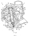
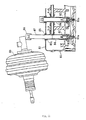
- FIG. 1 is a front view of a water-cooled, four-stroke cycle, V-type, 8-cylinder engine.
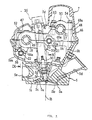
- FIG. 2 is a plan view of the cylinder head with its head cover removed.
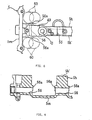
- FIG. 3 is a sectional view of part of the cylinder head where a plug pipe is attached, taken along the line III-III in FIG. 2.
- FIG. 4 is a sectional side view of the head cover with the plug pipe removed.
- FIG. 5 is a plan view of the head cover.
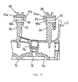
- FIG. 6 is a sectional view of part of the head cover where a solenoid valve and a cam angle sensor are attached.
- FIG. 7 is a sectional view of camshaft supporting part of the cylinder head.
- FIG. 8 is a plan view of a vertical wall portion of the cylinder head.
- FIG. 9 is a sectional view of a vertical wall portion of the cylinder head, as seen along the line IX-IX in FIG. 7.
- FIG. 10 is a sectional view of a vertical wall portion of the cylinder head, as seen along the line X-X.
- FIG. 1 a water-cooled, four-stroke cycle, V-type, 8-cylinder engine 1 mounted in the middle of a motor vehicle.
- right and left banks 2, 2 of cylinders are formed as a single cylinder block in a V shape, a crankcase 4 is connected and secured to the lower matching surface of the cylinder block, right and left cylinder heads 5, 5 are respectively placed on and secured to the upper matching surfaces of the right and left cylinder banks 2, 2, and right and left head covers 7, 7 are respectively placed on and secured to the upper matching surfaces of the right and left cylinder heads 5, 5.
- the right and left sides of the engine 1 as seen in the direction of the crankshaft 12 are almost symmetric, the constitution with the cylinder bank 2, the cylinder head 5, and the head cover 7 will be described only for the left side.
- the left side of the cylinder bank 2 is formed with four cylinder bores 2a positioned side by side. In each cylinder bore 2a is inserted a piston 10 for free sliding, with the piston 10 connected through a connecting rod 11 to the crankshaft 12.
- a combustion recess 5a is formed in the matching surface, on the cylinder bore 2a side, of the cylinder head 5.
- Each combustion recess 5a is formed with two intake openings 5b and two exhaust openings 5c.
- the intake opening 5b and the exhaust opening 5c are respectively provided with an intake valve 15 and an exhaust valve 16 to be opened and closed.
- the intake and exhaust valves 15, 16 are driven to open and close with an intake camshaft 17 and an exhaust camshaft 18 placed parallel to the crankshaft 12 through intake and exhaust rocker arms 19, 20.
- the intake valve 15 is placed above the cylinder axis B, and the exhaust valve 16 is placed below the cylinder axis B.
- a cam sprocket 24 is attached to the intake camshaft 17 and driven to rotate with the crankshaft 12 through a primary chain (not shown).
- a second cam sprocket 26 is attached to the exhaust camshaft 18 and driven with a first cam sprocket 25 attached to the intake camshaft 17 through a secondary chain (not shown).
- Each intake opening 5b in the cylinder head 5 is led toward the inside wall of the V shape of cylinder banks through an intake port 5d.
- Each intake port 5d is connected to an intake pipe 27a of an intake device 27 disposed inside the V shape of cylinder banks.
- Each exhaust opening 5c is led toward the outside wall of the V shape of cylinder banks through an exhaust port 5e.
- Each exhaust port 5e is connected to an exhaust pipe 28a of an exhaust device 28 located under the cylinder head 5.
- a fuel injection valve 29 is attached in nearly vertical attitude to a wall of the cylinder head 5 inside the V shape of cylinder banks.
- the nozzle 29a of the fuel injection valve 29 is directed toward the upper side of the intake valve 15.
- the cylinder head 5 is formed with vertical wall portions 5h in positions corresponding to the middle between adjacent cylinders.
- the upper matching surfaces 5h' of the vertical wall portions 5h are in the same height and parallel to the lower matching surface 5i of the cylinder head 5.
- the intake camshaft 17 is placed to extend across above the vertical wall portions 5h.
- the exhaust camshaft 18 is placed to extend across on the upper matching surfaces 5h'.
- the exhaust camshaft 18 is positioned so that the distance between the exhaust camshaft 18 and the crankshaft 12 in the direction of the cylinder axis B is shorter than the distance between the intake camshaft 17 and the crankshaft 12 (i.e. nearer to the center of the V bank). As a result, the axial length of the exhaust valve 16 is shorter than that of the intake valve 15. Also, since the exhaust camshaft 18 is placed nearer to the crankshaft 12, the width of the engine may be reduced by a dimension L in comparison with an arrangement in which the distance in the cylinder axis B direction between the exhaust camshaft 18', as shown with phantom lines in FIG. 1, and the crankshaft 12 is the same as the distance between the intake camshaft 17 and the crankshaft 12. As a result, the work of mounting the engine is facilitated accordingly.
- a cam supporting member 46 is placed on the upper matching surface 5h' of each of the vertical wall portions 5h.
- the cam supporting member 46 is formed integrally with an exhaust side cam cap portion 47 and an intake side cam carrier portion 48, with its the lower matching surface 46a in contact with the upper matching surface 5h' without a gap in between.
- An exhaust side cam journal receiver 49 is formed between the lower matching surface 46a of the exhaust side cam cap portion 47 and the upper matching surface 5h' of the vertical wall portion 5h, to support rotatably the journal portion of the exhaust camshaft 18.
- a head bolt inserting hole 5j is bored in the inside edge portion of the cam journal receiver 49 of the vertical wall portion 5h.
- the upper matching surface 48a of the intake side cam carrier portion 48 is formed parallel to the lower matching surface 46a of the cam supporting member 46.
- An intake cam cap 50 is attached to the upper matching surface 48a.
- An intake side cam journal receiver 51 is formed between the upper matching surface 48a of the intake side cam carrier portion 48 and the cam cap 50 to support rotatably the journal portion of the intake camshaft 17.
- a head bolt inserting hole 5k is bored in the inside marginal portion of the cam journal receiver 51 of the vertical wall portion 5h.
- the exhaust side cam cap portion 47 is secured to the vertical wall portion 5h by means of cam cap bolts 52, 52 inserted into both sides of the cam journal receiver 49.
- the intakes side cam cap 50 is secured to the cam carrier portion 48 by means of a cam cap bolt 53 inserted into the cylinder axis side of the cam journal receiver 50 and is also secured together with the cam carrier portion 48 to the vertical wall portion 5h by means of a cam cap bolt 54 inserted into the side, opposite the cylinder axis side, of the cam journal receiver 50.
- Rocker shafts 21, 22 supporting the intake, exhaust rocker arms 19 and 20 for rocking are respectively located on the outer side than the intake and exhaust camshafts 17, 18 with respect to the V shape of cylinder banks.
- the rocker arms 19, 20 are placed to extend in the same direction from the rocker shaft 21, 22 toward the inside of the V shape of cylinder banks.
- the intake side rocker shaft 21 is inserted into and supported with a shaft hole 55 formed with the lower matching surface 46a of the cam supporting member 46 and the upper matching surface 5h' of the vertical wall portion 5h.
- the circumferential edges of the shaft hale of the cam supporting member 46 forming the upper half of the shaft hole 55 are formed with semicircular thrust receiving portions 55a projecting in axial directions (see FIG. 10).
- the rocker shaft 22 on the exhaust side is inserted into and supported with a shaft hole 56 formed through the vertical wall portion 5h in a position above the outlet of the exhaust port 5e and near the inside surface of the outside wall portion 5m.
- a shaft hole 56 formed through the vertical wall portion 5h in a position above the outlet of the exhaust port 5e and near the inside surface of the outside wall portion 5m.
- Parts of the circumferential edges of the shaft hole 56, on the side opposite the outside wall portion 5m, are provided with thrust receiving portions 56a projecting in the axial directions (see FIGs. 8 and 9).
- the thrust receiving portions 56a are formed along about one-fourth of the circumferential edges of the shaft hole 56 on the side opposite the outside wall portion 5m.
- the intake and exhaust camshafts 17, 18 are provided with a variable timing mechanism (not shown) for variably controlling the opening and closing timing of the intake and exhaust valves 15, 16 according to operating conditions of the engine, and with a variable lift mechanism (not shown) for variably controlling the lift amounts of the intake and exhaust valves 15, 16 according to operating conditions of the engine.
- variable lift mechanism (not shown) is provided with low speed and high speed cams arranged side by side on a cam shaft and a rocker arm having independently rocking main rocker arm and sub-rocker arm, and is constituted to selectively switch the sub-rocker arm between an interlocked motion mode and a free motion mode relative to the main rocker arm directly interlocked with valve stems through a mode switching mechanism using hydraulic pressure supplied into a hollow part of the rocker shaft.
- Solenoid valves 31, 31 constituting drive sections of the variable valve timing mechanism and the variable valve lift mechanism are placed in the vicinity of the front ends of the intake and exhaust camshafts 17, 18.
- a cam angle sensor 32 for detecting the rotary angle of the intake camshaft 17 is inserted in a position above the camshaft 17 (see FIGs. 5 and 6).
- the solenoid valves 31, 31, and the cam angle sensor 32 are supported with the cam supporting member 46 to pass through insertion holes 7b, 7c bored in the head cover 7 and project upward. Seal members 41, 42 are fitted at the opening edges of the insertion holes 7b, 7c to seal up the gaps around the solenoid valves 31, 31, and the cam angle sensor 32.
- the insertion holes 7b, 7c are directed so that their axes C are parallel to the cylinder axis B.
- a plug screw hole 5f is formed in the center of each combustion chamber recess 5a of the cylinder head 5.
- An ignition plug 30 is screwed into the plug screw hole 5f, with the electrode 30a of the ignition plug 30 located in the combustion chamber recess 5a.
- the axis A of the plug screw hole 5f is tilted from the cylinder axis B toward the exhaust valve. Namely the angle of the axis A of the plug screw hole 5f is different from the angle of the axes C of the solenoid valve 31 and the cam angle sensor 32, so that the axis A of the plug screw hole 5f as seen in the camshaft axis direction intersects the axes C of the insertion holes 7b, 7c (also intersects the cylinder axis B).
- a plug pipe attachment hole 5g continuous from the plug screw hole 5e and greater in diameter than the plug screw hole 5e is formed in the cylinder head 5.
- the plug pipe attachment hole 5g is made large enough to insert the ignition plug 30.
- a pipe insertion hole 7a is formed in part of the head cover 7 opposite each plug pipe attachment hole 5g.
- the pipe insertion hole 7a is formed in a sunk portion 7d of the head cover 7, so that an ignition coil 35 to be described later is prevented from appearing above the top surface of the head cover 7.
- a cylindrical plug pipe 33 is inserted into the pipe insertion hole 7a.
- a coil member 34 is inserted in the ignition plug 30.
- the coil member 34 is made as a single member by inserting a plug cord 34b into a plastic-made plug cap 34a and connecting an ignition coil 35 on the top of it.
- the plug cord 34b may be electrically and mechanically connected to or disconnected from the terminal electrode 30b of the ignition plug 30.
- a connector 35a is connected through a lead cable to a battery (not shown).
- the plug pipe 33 is divided at the middle of its length into an upper pipe 36 and a lower pipe 37.
- the lower end of the lower pipe 37 is press-fitted and secured into the plug pipe attachment hole 5g.
- the lower end of the upper pipe 36 is formed with a skirt portion 36a greater in diameter than the lower pipe 37.
- a seal member 38 is fitted to the inside cylindrical surface of the skirt portion 36a, so that the seal member 38 comes into tight contact with the outside cylindrical surface of the lower pipe 37.
- the upper end of the upper pipe 36 is formed to be an integral flange portion 36b greater in diameter than the outside diameter of the pipe 36.
- a seal member 39 for coming into tight contact with the inside cylindrical surface of the plug insertion hole 7a is fitted around the outside cylindrical surface of the flange portion 36b.
- the top surface of the flange portion 36b is formed with a seal groove 36c extending in circumferential direction.
- a seal member 40 tightly attached to the top edge of the plug cap 34a engages watertightly with the seal groove 36c.
- the upper pipe 36 is made removable together with the coil member 34 from the head cover 7.
- the lower pipe 37 of the plug pipe 33 is secured by press-fitting into the plug pipe attachment hole 5g of the cylinder head 5. Also, the solenoid valves 31 and the cam angle sensor 32 are attached and secured to the cylinder head 5 and the cam cap 50.
- the head cover 7 is placed on the upper matching surface of the cylinder head 5 while positioning that the solenoid valves 31 and the cam angle sensor 32 are located in the insertion holes 7b and 7c, and the head cover 7 is tightened to the cylinder head 5 using bolts.
- the top surfaces of the solenoid valves 31 and the cam angle sensor 32 are different in height from each other. Therefore, when the solenoid valve 31 in the highest position on the right side in FIG. 6 is inserted in the insertion hole 7b, the solenoid valve 31 serves as a guide to insert the cam angle sensor 32 and the solenoid valve 31 located on the left in FIG. 6, so that the assembly work is facilitated.
- the upper pipe 36 containing the coil member 34 is inserted into the pipe insertion hole 7a of the head cover 7, the coil member 34 is fitted to the ignition plug 30, the skirt portion 36a is fitted to the lower pipe 37, and the flange portion 36b is fitted into the pipe support hole 7a.
- the upper pipe 36 is pulled out. Then a gap (a) appears corresponding to the size of the flange portion 36b between the upper pipe 36 and the pipe insertion hole 7a.
- the gap (a) is utilized to tilt the upper pipe 36 to an angle at which the upper pipe 36 does not stand in the way of a brake booster 89, and the coil member 34 is drawn out while it is tilted. After that the ignition plug 30 is removed using a tool inserted.
- the plug pipe 33 is made up of the upper pipe 36 and the lower pipe 37, the upper pipe 36 is provided with the integrally formed flange portion 36b, and the seal member 39 is fitted around the outside cylindrical surface of the flange portion 36b so that the seal member 39 is in tight contact with the pipe insertion hole 7a of the head cover 7. Therefore, the head cover 7 may be attached in the state of only the lower pipe 37 being fixed to the plug pipe attachment hole 5g of the cylinder head 5. That is, conventional, difficult assembly work of inserting the plug pipes while positioning all the plug pipes is made unnecessary, namely the work efficiency is improved.
- the gap (a) is made further greater, which further increases the freedom in direction and angle of removing the coil member 34 to further improve the ease of work of removing and attaching the coil member 34.
- the plug pipe 33 is made up of the upper and lower pipes 36 and 37, the solenoid valves 31 and the cam angle sensor 32 are first attached to the cylinder head 5 side and then the head cover 7 may be attached without interfering with the plug pipe 33.
- the axis A of the plug pipe attachment hole 5g intersects the axes C of the insertion holes 7b and 7c
- the head cover 7 cannot be attached once the solenoid valve 31 and others are attached.
- the present embodiment is arranged that the upper pipe 36 is attached after the head cover 7 is attached, the above problem is solved. This increases the freedom in the angles of attaching the solenoid valves 31 and the cam angle sensor 32.
- the engine width may be reduced by the dimension L in comparison with conventional arrangement. This enables to secure the clearance C (see FIG. 1) when the engine is mounted on a vehicle body.
- the cam support member 46 formed integrally with the exhaust side cam cap portion 47 and the intake side cam carrier 48 is placed on the upper matching surface 5h' of the vertical wall portion 5h of the cylinder head 5.
- the exhaust camshaft 18 is supported with the lower matching surface 46a of the exhaust side cam cap 48 and the upper matching surface 5h' of the vertical wall portion 5h.
- the intake camshaft 17 is supported with the upper matching surface 48a of the intake side cam carrier portion 48 and the intake cam cap 50 attached to the intake side cam carrier portion 48. Therefore, the upper matching surface 5h' of the cylinder head 5 can be made flat while locating the intake camshaft 17 and the exhaust camshaft 18 in different levels, and can be made parallel to the lower matching surface 5i on which the combustion recess 5a is formed.
- metallic dies for casting the cylinder head 5 can be made in a simple structure and moreover the reference surface for machining the upper and lower matching surfaces 5h' and 5i can be readily assured, resulting in more increased machinability.
- the rocker shaft 21 of the rocker arm 19 on the intake side is supported with the shaft hole 55 formed with the lower matching surface 46a of the cam support member 46 and the upper matching surface 5h' of the vertical wall portion 5h.
- the semicircular thrust receiving portions 55a are formed only along the shaft hole edge portions on the side of the cam support member 46. Therefore, in case the variable valve lift mechanism is to be disposed between the thrust receiving portions 55a of the rocker shaft 21, the distance between the thrust receiving portions 55a can be easily adjusted by machining the thrust receiving portions 55a, so that the variable valve lift mechanism of different specifications can be easily installed.
- the thrust receiving portions 55a are provided only on the side of the cam support member 46, machining of the thrust receiving portions 55a can be done in a single component state of the cam support member 46. Incidentally, if the thrust receiving portions 55a were formed along the entire circumferential edges of the shaft hole 55, the machining would have to be done in the state of the cam support member 46 combined to the cylinder head 5, which would be less easy to do.
- the thrust receiving portions 56a are formed along part of the circumferential edges of the shaft hole 56 opposite the outside wall portion 5m. Therefore, the end surfaces of the thrust receiving portions 56a can be machined easily without expanding outward the outside wall portion 5m. That is to say, as shown in FIG. 8, since the thrust receiving portion 56a is formed along about one-fourth of the circumferential edges of the shaft hole 56 on the side opposite the outside wall portion 5m, an end mill tool 60 does not interfere with the outside wall portion 5m when the end surfaces of the thrust receiving portions 56a are machined with the end mill tool 60.
- a plug pipe attaching structure for an internal combustion engine wherein a plug thread hole leading into a combustion chamber is bored in the combustion chamber's ceiling wall of a cylinder head, a plug pipe attaching hole greater in diameter than the plug thread hole is bored as continued from the plug thread hole, a pipe inserting hole is bored in part, opposite said plug pipe attaching hole, of a head cover tightened to the cylinder head, and a plug pipe into which a coil member connected to an ignition plug is removably inserted is passed through the pipe inserting hole and secured in the plug pipe attaching hole, and wherein said plug pipe is divided in the middle of its length into an upper pipe and a lower pipe, the upper end of the upper pipe is provided with a sealing member for coming in tight contact with the inside cylindrical surface of the pipe inserting hole, and the upper pipe is adapted to be removable together with the coil member from the head cover.
- the plug pipe is made up of two parts, the lower pipe fixed into the plug pipe attaching hole and the upper pipe that can be drawn out through the pipe inserting hole of the head cover, and the gap between the pipe inserting hole and the upper pipe is sealed up with the sealing member attached to the upper pipe. Therefore, when the head cover is to be attached, first the lower pipe only is secured to the cylinder head and in that state the head cover is attached and secured. In that case, since the lower pipe remains in the head cover, alignment is unnecessary between the plug pipe and the pipe inserting hole. Then the head cover is attached and the upper pipe is inserted through the pipe supporting hole.
- the upper pipes are inserted one by one after attaching the head cover. Therefore, conventional, difficult work of simultaneously inserting all the plug pipes while aligning them with the plug inserting holes is made unnecessary, and the work efficiency is improved.
- the sealing member to come into tight contact with the inside circumferential surface of the pipe inserting hole is attached around the upper end portion of the upper pipe, the diameter of the pipe inserting hole is greater by the dimension corresponding to the diameter of the sealing member.
- the upper pipe maybe drawn out in oblique direction that is not in the way of vehicle components. In this regard too, work efficiency is improved.
- the upper end of said upper pipe is formed with a flange portion greater in diameter than the outside diameter of said upper pipe, and said sealing member is attached to the outside cylindrical surface of said flange portion.
- the inside diameter of the pipe inserting hole may be increased by a dimension corresponding to the dimension of the flange portion.
- the clearance between the flange portion of the upper pipe and the inserting hole is further increased. This makes it possible to further increase the freedom of direction and angle of drawing out the coil member, which means additional improvement in the ease of work.
- engine components are mounted on the cylinder head side so as to project above the head cover, with the axis angle of the engine components being different from the axis angle the plug pipe.
- a plug pipe attachment structure for internal combustion engines that makes it possible to eliminate time-consuming work associated with attaching the head cover to the cylinder head and also to facilitate inspection and replacement of ignition plugs, wherein in case a plug thread hole 5f leading into a combustion chamber of a cylinder head 5 is bored in the combustion chamber's ceiling wall 5a, a plug pipe attaching hole 5g of a greater diameter than that of the plug thread hole 5f is bored as continued from the plug thread hole 5f, a pipe inserting hole 7a is bored in part, opposite the plug pipe attaching hole 5g of a head cover 7 tightened to the cylinder head 5, and a plug pipe 33 into which a coil member 34 connected to an ignition plug 30 is removably inserted is passed through the pipe inserting hole 7a and secured in the plug pipe attaching hole 5g said plug pipe 33 is divided in the middle of its length into an upper pipe 36 and a lower pipe 37, the upper end of the upper pipe 36 is provided with a sealing member 39 for coming in tight contact with the inside round surface of
Landscapes
- Engineering & Computer Science (AREA)
- Chemical & Material Sciences (AREA)
- Combustion & Propulsion (AREA)
- Mechanical Engineering (AREA)
- General Engineering & Computer Science (AREA)
- Cylinder Crankcases Of Internal Combustion Engines (AREA)
- Ignition Installations For Internal Combustion Engines (AREA)
- Valve-Gear Or Valve Arrangements (AREA)
Applications Claiming Priority (2)
| Application Number | Priority Date | Filing Date | Title |
|---|---|---|---|
| JP2001080827A JP2002276523A (ja) | 2001-03-21 | 2001-03-21 | 内燃機関のプラグパイプ取付け構造 |
| JP2001080827 | 2001-03-21 |
Publications (2)
| Publication Number | Publication Date |
|---|---|
| EP1243780A2 true EP1243780A2 (de) | 2002-09-25 |
| EP1243780A3 EP1243780A3 (de) | 2003-06-04 |
Family
ID=18937037
Family Applications (1)
| Application Number | Title | Priority Date | Filing Date |
|---|---|---|---|
| EP02006406A Withdrawn EP1243780A3 (de) | 2001-03-21 | 2002-03-21 | Brennkraftmaschine |
Country Status (3)
| Country | Link |
|---|---|
| US (1) | US6561153B2 (de) |
| EP (1) | EP1243780A3 (de) |
| JP (1) | JP2002276523A (de) |
Families Citing this family (12)
| Publication number | Priority date | Publication date | Assignee | Title |
|---|---|---|---|---|
| US6705269B2 (en) * | 2000-11-16 | 2004-03-16 | Honda Giken Kogyo Kabushiki Kaisha | Four-cycle engine |
| US20030175242A1 (en) * | 2001-09-17 | 2003-09-18 | Micheal Gruenberg | Cell therapy system |
| US20080276918A1 (en) * | 2007-05-11 | 2008-11-13 | Skinner Albert A | Integrated ignition coil and oil seal for head and cam cover |
| KR100926555B1 (ko) | 2007-12-13 | 2009-11-12 | 현대자동차주식회사 | 엔진용 점화플러그 튜브 유닛 |
| JP5140529B2 (ja) * | 2008-09-25 | 2013-02-06 | 本田技研工業株式会社 | 自動二輪車用単気筒エンジン |
| JP6469850B2 (ja) * | 2014-09-18 | 2019-02-13 | イートン ソチエタ・レスポンサビリタ・リミタータEaton SRL | エンジン制動用のロッカアームアセンブリ |
| JP2016114076A (ja) * | 2014-12-11 | 2016-06-23 | 内山工業株式会社 | ガスケット組付確認構造 |
| JP6449656B2 (ja) * | 2015-01-14 | 2019-01-09 | 日野自動車株式会社 | プラグパイプの取付構造 |
| JP6458864B2 (ja) * | 2015-05-25 | 2019-01-30 | 日産自動車株式会社 | 内燃機関 |
| JP6839576B2 (ja) * | 2017-03-21 | 2021-03-10 | 本田技研工業株式会社 | Dohc型内燃機関 |
| CN111954755B (zh) * | 2018-04-10 | 2022-09-20 | 日产自动车株式会社 | 内燃机的燃烧室构造 |
| DE102019123721B4 (de) * | 2019-09-04 | 2021-09-30 | Man Energy Solutions Se | Kipphebeldeckel mit Zündkerzenkontaktierung für eine Brennkraftmaschine |
Citations (6)
| Publication number | Priority date | Publication date | Assignee | Title |
|---|---|---|---|---|
| GB556790A (en) * | 1942-06-12 | 1943-10-21 | William John Morison | Improvements relating to sparking plugs and means for mounting the same |
| DE760104C (de) * | 1940-11-21 | 1952-10-20 | Carl F W Borgward | Zylinderkopf fuer Brennkraftmaschinen |
| US4637358A (en) * | 1984-09-27 | 1987-01-20 | Honda Giken Kogyo Kabushiki Kaisha | Spark plug cap apparatus |
| US4727833A (en) * | 1985-11-18 | 1988-03-01 | Toyota Jidosha Kabushiki Kaisha | Sealing structure of cylinder head cover |
| FR2655386A1 (fr) * | 1989-12-01 | 1991-06-07 | Peugeot | Dispositif de fixation amovible sur une culasse de moteur d'un ensemble constitue par une bobine d'allumage et une bougie. |
| JP2000252040A (ja) * | 1999-03-03 | 2000-09-14 | Ngk Spark Plug Co Ltd | コイル一体型点火プラグ |
Family Cites Families (4)
| Publication number | Priority date | Publication date | Assignee | Title |
|---|---|---|---|---|
| US6209507B1 (en) * | 1992-10-19 | 2001-04-03 | Yamaha Hatsudoki Kabushiki Kaisha | Valve mechanism for internal combustion engine |
| JPH07197848A (ja) * | 1993-12-29 | 1995-08-01 | Yamaha Motor Co Ltd | 多気筒エンジンのシリンダヘッド |
| JPH08277746A (ja) * | 1995-04-04 | 1996-10-22 | Yamaha Motor Co Ltd | 内燃エンジン |
| JP2001090513A (ja) * | 1999-09-27 | 2001-04-03 | Yamaha Motor Co Ltd | バルブリフタの装着構造 |
-
2001
- 2001-03-21 JP JP2001080827A patent/JP2002276523A/ja not_active Withdrawn
-
2002
- 2002-03-12 US US10/063,013 patent/US6561153B2/en not_active Expired - Fee Related
- 2002-03-21 EP EP02006406A patent/EP1243780A3/de not_active Withdrawn
Patent Citations (6)
| Publication number | Priority date | Publication date | Assignee | Title |
|---|---|---|---|---|
| DE760104C (de) * | 1940-11-21 | 1952-10-20 | Carl F W Borgward | Zylinderkopf fuer Brennkraftmaschinen |
| GB556790A (en) * | 1942-06-12 | 1943-10-21 | William John Morison | Improvements relating to sparking plugs and means for mounting the same |
| US4637358A (en) * | 1984-09-27 | 1987-01-20 | Honda Giken Kogyo Kabushiki Kaisha | Spark plug cap apparatus |
| US4727833A (en) * | 1985-11-18 | 1988-03-01 | Toyota Jidosha Kabushiki Kaisha | Sealing structure of cylinder head cover |
| FR2655386A1 (fr) * | 1989-12-01 | 1991-06-07 | Peugeot | Dispositif de fixation amovible sur une culasse de moteur d'un ensemble constitue par une bobine d'allumage et une bougie. |
| JP2000252040A (ja) * | 1999-03-03 | 2000-09-14 | Ngk Spark Plug Co Ltd | コイル一体型点火プラグ |
Non-Patent Citations (1)
| Title |
|---|
| PATENT ABSTRACTS OF JAPAN vol. 2000, no. 12, 3 January 2001 (2001-01-03) & JP 2000 252040 A (NGK SPARK PLUG CO LTD), 14 September 2000 (2000-09-14) * |
Also Published As
| Publication number | Publication date |
|---|---|
| JP2002276523A (ja) | 2002-09-25 |
| EP1243780A3 (de) | 2003-06-04 |
| US6561153B2 (en) | 2003-05-13 |
| US20020134341A1 (en) | 2002-09-26 |
Similar Documents
| Publication | Publication Date | Title |
|---|---|---|
| US4793297A (en) | Valve operating mechanism for internal combustion engine | |
| EP1243780A2 (de) | Brennkraftmaschine | |
| US4796574A (en) | SOHC type internal combustion engine | |
| US5127380A (en) | Combustion chamber and valve operating mechanism for multi-valve engine | |
| US5535714A (en) | Cylinder head arrangement for multi-valve engine | |
| US4534325A (en) | Cam shaft holding system for internal combustion engine | |
| US6895942B2 (en) | Engine fuel pump mounting structure | |
| US4762099A (en) | Valve actuating device of four-cycle internal combustion engine | |
| EP0688939B1 (de) | Zylinderkopfanordnung für eine Mehrventil-Brennkraftmaschine mit obenliegender Nockenwelle | |
| EP1243760A2 (de) | Brennkraftmaschine | |
| EP0611883B1 (de) | Brennkraftmaschine | |
| US5119776A (en) | Compact bearing cap for overhead camshaft | |
| EP1344930B1 (de) | Brennkraftmaschine mit Kraftstoffeinspritzventil | |
| US8166938B2 (en) | Engine camshaft cover with integrated oil passages for camshaft phaser actuation | |
| EP0957259B1 (de) | Brennkraftmaschine | |
| EP1273784B1 (de) | Zylinderkopf für eine viertakt Brennkraftmaschine | |
| CN100465414C (zh) | 发动机 | |
| US4223647A (en) | Slanted internal combustion engine | |
| KR20040026600A (ko) | 오버헤드캠형 내연기관 | |
| JP2584601B2 (ja) | 内燃機関の動弁装置 | |
| EP0713958B1 (de) | Brennkraftmaschine | |
| JPS6339363Y2 (de) | ||
| EP0434638A1 (de) | Fremdgezündete Brennkraftmaschine mit zwei obenliegenden Nockenwellen für Fahrzeuge | |
| JPH0413422Y2 (de) | ||
| JPH063131Y2 (ja) | 動弁装置のカム軸潤滑構造 |
Legal Events
| Date | Code | Title | Description |
|---|---|---|---|
| PUAI | Public reference made under article 153(3) epc to a published international application that has entered the european phase |
Free format text: ORIGINAL CODE: 0009012 |
|
| AK | Designated contracting states |
Kind code of ref document: A2 Designated state(s): AT BE CH CY DE DK ES FI FR GB GR IE IT LI LU MC NL PT SE TR |
|
| AX | Request for extension of the european patent |
Free format text: AL;LT;LV;MK;RO;SI |
|
| PUAL | Search report despatched |
Free format text: ORIGINAL CODE: 0009013 |
|
| AK | Designated contracting states |
Designated state(s): AT BE CH CY DE DK ES FI FR GB GR IE IT LI LU MC NL PT SE TR |
|
| AX | Request for extension of the european patent |
Extension state: AL LT LV MK RO SI |
|
| 17P | Request for examination filed |
Effective date: 20031204 |
|
| AKX | Designation fees paid |
Designated state(s): AT BE CH CY DE DK ES FI FR GB GR IE IT LI LU MC NL PT SE TR |
|
| GRAP | Despatch of communication of intention to grant a patent |
Free format text: ORIGINAL CODE: EPIDOSNIGR1 |
|
| STAA | Information on the status of an ep patent application or granted ep patent |
Free format text: STATUS: THE APPLICATION IS DEEMED TO BE WITHDRAWN |
|
| 18D | Application deemed to be withdrawn |
Effective date: 20070109 |