EP0936119B1 - Porte pivotante coulissante pour véhicules - Google Patents
Porte pivotante coulissante pour véhicules Download PDFInfo
- Publication number
- EP0936119B1 EP0936119B1 EP99890048A EP99890048A EP0936119B1 EP 0936119 B1 EP0936119 B1 EP 0936119B1 EP 99890048 A EP99890048 A EP 99890048A EP 99890048 A EP99890048 A EP 99890048A EP 0936119 B1 EP0936119 B1 EP 0936119B1
- Authority
- EP
- European Patent Office
- Prior art keywords
- door
- hook
- door leaf
- sliding door
- closing edge
- Prior art date
- Legal status (The legal status is an assumption and is not a legal conclusion. Google has not performed a legal analysis and makes no representation as to the accuracy of the status listed.)
- Expired - Lifetime
Links
Images


Classifications
-
- B—PERFORMING OPERATIONS; TRANSPORTING
- B61—RAILWAYS
- B61D—BODY DETAILS OR KINDS OF RAILWAY VEHICLES
- B61D19/00—Door arrangements specially adapted for rail vehicles
- B61D19/003—Door arrangements specially adapted for rail vehicles characterised by the movements of the door
- B61D19/009—Door arrangements specially adapted for rail vehicles characterised by the movements of the door both sliding and plugging, (e.g. for refrigerator cars)
-
- B—PERFORMING OPERATIONS; TRANSPORTING
- B61—RAILWAYS
- B61D—BODY DETAILS OR KINDS OF RAILWAY VEHICLES
- B61D19/00—Door arrangements specially adapted for rail vehicles
- B61D19/02—Door arrangements specially adapted for rail vehicles for carriages
- B61D19/026—Safety devices for preventing passengers from being injured by movements of doors or variations in air pressure
-
- E—FIXED CONSTRUCTIONS
- E05—LOCKS; KEYS; WINDOW OR DOOR FITTINGS; SAFES
- E05D—HINGES OR SUSPENSION DEVICES FOR DOORS, WINDOWS OR WINGS
- E05D15/00—Suspension arrangements for wings
- E05D15/06—Suspension arrangements for wings for wings sliding horizontally more or less in their own plane
- E05D15/10—Suspension arrangements for wings for wings sliding horizontally more or less in their own plane movable out of one plane into a second parallel plane
- E05D15/1065—Suspension arrangements for wings for wings sliding horizontally more or less in their own plane movable out of one plane into a second parallel plane with transversely moving track
- E05D15/1068—Suspension arrangements for wings for wings sliding horizontally more or less in their own plane movable out of one plane into a second parallel plane with transversely moving track specially adapted for use in railway-cars or mass transit vehicles
-
- E—FIXED CONSTRUCTIONS
- E05—LOCKS; KEYS; WINDOW OR DOOR FITTINGS; SAFES
- E05D—HINGES OR SUSPENSION DEVICES FOR DOORS, WINDOWS OR WINGS
- E05D15/00—Suspension arrangements for wings
- E05D15/06—Suspension arrangements for wings for wings sliding horizontally more or less in their own plane
- E05D15/10—Suspension arrangements for wings for wings sliding horizontally more or less in their own plane movable out of one plane into a second parallel plane
- E05D2015/1028—Suspension arrangements for wings for wings sliding horizontally more or less in their own plane movable out of one plane into a second parallel plane with only the wing moving transversely
- E05D2015/1031—Suspension arrangements for wings for wings sliding horizontally more or less in their own plane movable out of one plane into a second parallel plane with only the wing moving transversely the wing supported on arms extending from the carriage
-
- E—FIXED CONSTRUCTIONS
- E05—LOCKS; KEYS; WINDOW OR DOOR FITTINGS; SAFES
- E05D—HINGES OR SUSPENSION DEVICES FOR DOORS, WINDOWS OR WINGS
- E05D15/00—Suspension arrangements for wings
- E05D15/06—Suspension arrangements for wings for wings sliding horizontally more or less in their own plane
- E05D15/10—Suspension arrangements for wings for wings sliding horizontally more or less in their own plane movable out of one plane into a second parallel plane
- E05D15/1065—Suspension arrangements for wings for wings sliding horizontally more or less in their own plane movable out of one plane into a second parallel plane with transversely moving track
- E05D2015/1084—Suspension arrangements for wings for wings sliding horizontally more or less in their own plane movable out of one plane into a second parallel plane with transversely moving track the carriage being directly linked to the fixed frame, e.g. slidingly
- E05D2015/1086—Suspension arrangements for wings for wings sliding horizontally more or less in their own plane movable out of one plane into a second parallel plane with transversely moving track the carriage being directly linked to the fixed frame, e.g. slidingly swingingly, e.g. on arms
-
- E—FIXED CONSTRUCTIONS
- E05—LOCKS; KEYS; WINDOW OR DOOR FITTINGS; SAFES
- E05Y—INDEXING SCHEME RELATING TO HINGES OR OTHER SUSPENSION DEVICES FOR DOORS, WINDOWS OR WINGS AND DEVICES FOR MOVING WINGS INTO OPEN OR CLOSED POSITION, CHECKS FOR WINGS AND WING FITTINGS NOT OTHERWISE PROVIDED FOR, CONCERNED WITH THE FUNCTIONING OF THE WING
- E05Y2201/00—Constructional elements; Accessories therefore
- E05Y2201/20—Brakes; Disengaging means, e.g. clutches; Holders, e.g. locks; Stops; Accessories therefore
- E05Y2201/218—Holders
- E05Y2201/22—Locks
-
- E—FIXED CONSTRUCTIONS
- E05—LOCKS; KEYS; WINDOW OR DOOR FITTINGS; SAFES
- E05Y—INDEXING SCHEME RELATING TO HINGES OR OTHER SUSPENSION DEVICES FOR DOORS, WINDOWS OR WINGS AND DEVICES FOR MOVING WINGS INTO OPEN OR CLOSED POSITION, CHECKS FOR WINGS AND WING FITTINGS NOT OTHERWISE PROVIDED FOR, CONCERNED WITH THE FUNCTIONING OF THE WING
- E05Y2201/00—Constructional elements; Accessories therefore
- E05Y2201/60—Suspension or transmission members; Accessories therefore
- E05Y2201/606—Accessories therefore
- E05Y2201/608—Back-drive
-
- E—FIXED CONSTRUCTIONS
- E05—LOCKS; KEYS; WINDOW OR DOOR FITTINGS; SAFES
- E05Y—INDEXING SCHEME RELATING TO HINGES OR OTHER SUSPENSION DEVICES FOR DOORS, WINDOWS OR WINGS AND DEVICES FOR MOVING WINGS INTO OPEN OR CLOSED POSITION, CHECKS FOR WINGS AND WING FITTINGS NOT OTHERWISE PROVIDED FOR, CONCERNED WITH THE FUNCTIONING OF THE WING
- E05Y2201/00—Constructional elements; Accessories therefore
- E05Y2201/60—Suspension or transmission members; Accessories therefore
- E05Y2201/606—Accessories therefore
- E05Y2201/62—Synchronisation of transmission members
-
- E—FIXED CONSTRUCTIONS
- E05—LOCKS; KEYS; WINDOW OR DOOR FITTINGS; SAFES
- E05Y—INDEXING SCHEME RELATING TO HINGES OR OTHER SUSPENSION DEVICES FOR DOORS, WINDOWS OR WINGS AND DEVICES FOR MOVING WINGS INTO OPEN OR CLOSED POSITION, CHECKS FOR WINGS AND WING FITTINGS NOT OTHERWISE PROVIDED FOR, CONCERNED WITH THE FUNCTIONING OF THE WING
- E05Y2900/00—Application of doors, windows, wings or fittings thereof
- E05Y2900/50—Application of doors, windows, wings or fittings thereof for vehicles
- E05Y2900/51—Application of doors, windows, wings or fittings thereof for vehicles for railway cars or mass transit vehicles
Definitions
- the invention relates to a sliding door for vehicles with at least one door wing, with a Mosbaumrohr in the area of the secondary closing edge of each door leaf and with a locking device for each door at its Hauptsch Strukturkante, wherein at least one hook in the Area of the secondary closing edge is provided.
- the problem underlying the invention is not involved High-speed trains together, but with the significant Trend to increase the driving speed, too of suburban and suburban trains to improve efficiency increase predetermined routes and around the railroad to make it more attractive as a means of mass transit.
- the thereby driven speeds are enough to those of Of course, not high-speed trains, but especially when passing through tunnels or at Switzerlandsbegegnungen pressure surges on the side walls of the Wagons on, which cause the door leaves clearly bulge out and leave their seat on the door frame.
- the invention provides to achieve these objectives that the hook by the twist of the Matbaumrohres between a door releasing position and a Door leaf, at least substantially in the closed Position holding position is movable.
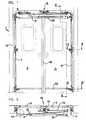
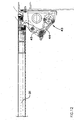
- Fig. 1 there is an inventive Door 1 consists of two door leaves 2, 3, which are in one in his Entity arranged with 4 designated frame. The Connection between the doors and the frame will by a leader designated 5 in its entirety Drive device manufactured and secured.
- To guide and drive mechanism 5 include both a Linear drive 6, which acts on the door 2, as well an unillustrated synchronization mechanism, for example an endlessly circulating band, with a wing with one and the other wing with the other strand connected, as well as the actual guiding elements, like the two door tree tubes 7, 8 and the associated guides and roles, both at the door top and on the door base.
- a Linear drive 6 which acts on the door 2
- an unillustrated synchronization mechanism for example an endlessly circulating band
- the hub 11 carries a Connecting rod 12 which is on a safety gear 13th affects and the area of the upper corners of the door leaves 2, 3 in the region of the main closing edge 14 after fixed closed.
- a section along the Line III-III of Fig. 1 shows, is the vehicle profile heavily cambered, almost kinked, and does the attachment of a continuous Schobaumrohres almost impossible.
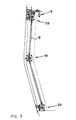
- the Invention the need for the division of the Mosbaumrohres to use and sees at least in the division one additional holding device for the door leaf in the areas the strongest bulge near the minor closing edge 15 in front.
- the Schosterrohr 8 is in the area designated in its entirety by 16 Retaining mechanism rotatably mounted on a support plate 17.
- the up and down leading continuations of the Matbaumrohres at the free ends are cardan on per se stored known manner.
- In the area of the holding mechanism 16 is rotatably connected to the Matbaumrohr 8 an angle 18, on which in turn articulated a coupling piece 19 is.
- the coupling piece 19 is provided with a hook 20 hingedly connected, which in turn about a hook axis 21st is pivotable.
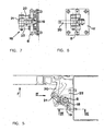
- Fig. 5 is the solid lines the closed, holding position of the hook 20 and the Mosbaumrohres 8 registered and with thin lines the releasing Position. It can be seen that in the heavily registered, locked position even by a large one Force F outward, as with pressure differences, but even in the case of pushing passengers to the door, occurs, no force component or no moment on the Hook 20 and the holding mechanism 16 acts, which is a release could cause the same.
- the holding mechanism 16 and the Hook 20 does not serve to close the door leaf and not even pressing the door leaf to the frame while driving the train. It must therefore the Retaining mechanism 16 neither during closing nor transfer significant forces during the journey. Just during train movements, driveways in tunnels or Putting off passengers is to absorb the forces that come from the door. It is therefore quite advantageous when the hook 20 during closing and even while driving a short distance from the Mauscheuxkante is or at least not noticeable Forces transmit.
- This over-dead-center mechanism can do that too be characterized in that the three pivot axes in the releasing position a triangle with opposite Define orientation to the triangle in a holding position: Meant are thus the pivot axis between the hook 20th and the coupling piece 19; the pivot axis between the Coupling piece 19 and the angle 18; and the axis of the Door tree pipe 8.
- the more detailed structure of the holding mechanism 16 is also in Cohesion with Figs. 6 and 7, which only in the closed position show, in more detail. there one recognizes in particular the axle holder 22 for the hook axis 21, and for reasons of stability and load Double-aligned dome piece 19.
- a combined guiding and holding mechanism 23 can be seen as he both in the upper and in the lower area of the door 1 can be arranged.
- This Guide and support mechanism 23 works similar to the Holding mechanism 16, except that it is at its door-side end no hook 20 carries, but a pair of rollers 24, the Door leaf 3 along a guide 25 (Fig. 1) leads.
- This Pair of rollers 24 is seated on a pivot plate 26, the order a pivot axis 27 parallel to the Matbaumrohr 8 in the area the guide and holding mechanism 23 is pivotable.
- the pivoting of the pivot plate 26 is analogous to Holding mechanism 16 via a cranked coupling piece 28, from Fig. 4 it can be seen that in the closed position the cranked coupling piece 28 in one Over-dead-point is located, so that by exercising a Force F on the door leaf 3 in its closed position no forces or no moments on the guide holding mechanism 23 may arise, which lead to an opening of the door would.
- Fig. 8 shows a variant of the embodiment of the Fig. 4, wherein instead of the joint chain a slotted guide is provided with a pin 29 and a link 30, which have the same effects as the link chain of Fig. 4.
- a door leaf 31, on any, further down explained way is carried out by means of a linear drive 32, which acts on a door leaf fixed arm 33, emotional.
- the Austellterrorism the door and the guide along the carbody outer wall is by a door wing side Guide 34 and rollers 35 mounted on a pivot plate 36 mounted, accomplished.
- the arm 33 is above a first leg of a pivoting arm 36 connected to the linear drive 32.
- the second Leg of the pivot arm 36 engages in a guide 37 a and causes the pivoting of the pivot arm 36 to Beginning of the opening or at the end of the closing movement of Door. By this pivoting movement is achieved that the translatory movement of the door is greater than the movement of the linear drive.
- the swivel arm takes over 36, who sits on a slide 37, turn on a support tube 38 is displaceable, and the bearing Function for the door leaf 31, but this is not necessary.
- a linear drive is the selected embodiment provided a revolving rope, as this from the straight, direct direction between the pulleys, of which one is the drive roller, can be swung out, without it being damaged.
- the inventively provided protection against buckling of the door leaf takes place at the main closing edge 39 a V-shaped design of the door wing, a bridge 40 of the portal frame so that a buckling in the direction of the arrow F is reliably prevented.
- a V-shaped design of the door edge area can also be provided individual bars 41 at a suitable distance his. Under certain circumstances, only such a sufficient Rod 41 approximately in the middle of the door height.
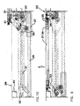
- the Superschsch Congress 42 is at the Tuerber- or door lower edge by the guide rollers 35 and the guide 34, in this area (FIG. 11) provided analogously to each other are secured.
- Tumblers 43 are provided, which are similar to the retaining mechanism 16 of the first variant work. It is in this Case between the hook and the door tree pipe a coupling rod 44 provided, the hook 45 between the closed position (thick) and the open position (pulled out dashed) swung back and forth.
- a continuous parallel shaft 46 is provided the only partially formed shaft pieces of first variant according to FIGS. 1 to 8 replaced. This can especially with the little domed doors as shown Embodiment for ease of assembly practical be, because then the entire Materkomplex on one single mounting plate can be arranged, the only in its entirety on the car body to assemble and to adjust is.
- Fig. 11 also shows that the holding mechanisms 43 in their dimensions on the crowning of the car body Have consideration while the guide-holding mechanisms 47, as far as this is possible, be made equal to the manufacturing and Reduce storage costs.
- the invention is not limited to the illustrated embodiments limited, but can be modified variously become. So it is possible to have other guides for to use the door leaves or another mechanism to use to drive the Mitbaumrohres, which also no Must be over-dead-point mechanism.
Claims (4)
- Porte pivotante coulissante pour véhicules avec au moins un vantail de porte, comportant un tube de montant de porte (7, 8) dans la zone de l'arête de fermeture latérale (15, 42) de chaque vantail de porte (2, 3, 31) et au moins un dispositif de verrouillage pour chaque vantail de porte sur son arête de fermeture principale, au moins un crochet (20, 45) étant prévu dans la zone de l'arête de fermeture latérale (15, 42), caractérisée en ce que par rotation du tube de montant de porte (7, 8) le crochet (20, 45) est mobile entre une position libérant le vantail de porte (2, 3, 31) et une position maintenant le vantail de porte au moins sensiblement dans l'état fermé.
- Porte pivotante coulissante selon la revendication 1, caractérisée en ce que le crochet (20, 45) est mobile en pivotement autour d'un axe parallèle au tube de montant de porte (7, 8) et est pivoté par une pièce d'accouplement (19, 44) dont la première extrémité est reliée en articulation au crochet et dont la deuxième extrémité est reliée en articulation au tube de montant de porte (7, 8).
- Porte pivotante coulissante selon la revendication 2, caractérisée en ce que les axes de pivotement du crochet (20, 45) de la pièce d'accouplement (19, 44) et du tube de montant de porte (7, 8) sont agencés de telle sorte que dans la position verrouillée du crochet celui-ci se trouve dans une position de dépassement de point mort.
- Porte pivotante coulissante selon l'une des revendications précédentes, caractérisée en ce que le tube de montant de porte (7, 8) est subdivisé en tronçons qui sont reliés entre eux à la Cardan.
Priority Applications (1)
| Application Number | Priority Date | Filing Date | Title |
|---|---|---|---|
| AT99890048T ATE249950T1 (de) | 1998-02-10 | 1999-02-09 | Schwenkschiebetür für fahrzeuge |
Applications Claiming Priority (2)
| Application Number | Priority Date | Filing Date | Title |
|---|---|---|---|
| AT0023898A AT409616B (de) | 1998-02-10 | 1998-02-10 | Schwenkschiebetür für ein fahrzeug |
| AT23898 | 1998-02-10 |
Publications (2)
| Publication Number | Publication Date |
|---|---|
| EP0936119A1 EP0936119A1 (fr) | 1999-08-18 |
| EP0936119B1 true EP0936119B1 (fr) | 2003-09-17 |
Family
ID=3485229
Family Applications (1)
| Application Number | Title | Priority Date | Filing Date |
|---|---|---|---|
| EP99890048A Expired - Lifetime EP0936119B1 (fr) | 1998-02-10 | 1999-02-09 | Porte pivotante coulissante pour véhicules |
Country Status (4)
| Country | Link |
|---|---|
| EP (1) | EP0936119B1 (fr) |
| AT (2) | AT409616B (fr) |
| DE (1) | DE59906977D1 (fr) |
| ES (1) | ES2205756T3 (fr) |
Families Citing this family (15)
| Publication number | Priority date | Publication date | Assignee | Title |
|---|---|---|---|---|
| DE202004002908U1 (de) * | 2004-02-25 | 2004-05-06 | Gebr. Bode Gmbh & Co. Kg | Vorrichtung zur Verriegelung einer Schwenkschiebetür für Fahrzeuge zur Personenbeförderung, insbesondere Fahrzeuge des öffentlichen Personennahverkehrs |
| DE102004045072A1 (de) * | 2004-09-15 | 2006-03-30 | Hübner GmbH | Schwenktür eines Busses oder eines schienengebundenen Fahrzeuges, umfassend mindestens einen Türflügel |
| AT501468B8 (de) * | 2005-02-17 | 2007-02-15 | Knorr Bremse Gmbh | Schwenkschiebetür |
| EP2218601A4 (fr) * | 2007-10-26 | 2013-01-23 | Train Automatic Solutions In & Out Tasio | Système de translation et d'actionnement de blocage de portes coulissantes |
| ES2354004T3 (es) | 2008-09-18 | 2011-03-09 | TER GmbH Komponenten für Aufzüge und Verkehrsmittel | Dispositivo de guía y enclavamiento de un sistema de puerta pivotante corrediza. |
| CN101767593B (zh) * | 2010-01-11 | 2012-06-13 | 南京康尼机电股份有限公司 | 十字滑块式塞拉门机构 |
| KR101172731B1 (ko) | 2010-05-17 | 2012-08-14 | 흥일기업주식회사 | 철도차량용 플러그 도어 록킹장치 |
| CN102001344B (zh) * | 2010-11-01 | 2013-05-29 | 南京康尼机电股份有限公司 | 铁路车辆门系统承载驱动机构 |
| AT514630B1 (de) * | 2013-08-14 | 2015-04-15 | Siemens Ag Oesterreich | Verfahren und Vorrichtung zur Verriegelung einer Schienenfahrzeugschiebetüre |
| JP7042093B2 (ja) * | 2018-01-30 | 2022-03-25 | ナブテスコ株式会社 | プラグドア装置 |
| CN109204353A (zh) * | 2018-11-19 | 2019-01-15 | 西南交通大学 | 自走行装备运载列车的液压门控系统 |
| CN109318916B (zh) * | 2018-11-23 | 2024-02-13 | 中车长春轨道客车股份有限公司 | 高速列车内藏门系统装配用综合定位装置 |
| FR3095616B1 (fr) * | 2019-04-30 | 2022-12-16 | Faiveley Transp Tours | Ensemble comprenant un vantail et un dispositif de guidage pour porte louvoyante coulissante, procédé de montage et véhicule ainsi équipé |
| CN110450801A (zh) * | 2019-07-19 | 2019-11-15 | 中车青岛四方机车车辆股份有限公司 | 单扇塞拉门及具有该单扇塞拉门的轨道车辆 |
| DE102022124520A1 (de) * | 2022-09-23 | 2024-03-28 | Brose Fahrzeugteile Se & Co. Kommanditgesellschaft, Bamberg | Verfahren und Absperrsystem zum Absperren eines Fahrzeuges |
Family Cites Families (6)
| Publication number | Priority date | Publication date | Assignee | Title |
|---|---|---|---|---|
| DE2140793C3 (de) * | 1971-08-14 | 1974-05-02 | Fa. Carl Sievers, 5628 Heiligenhaus | Verschluß für Außenschiebetüren, insbesondere von Schienenfahrzeugen |
| DE2166063C3 (de) * | 1971-08-14 | 1978-06-08 | Fa. Carl Sievers, 5628 Heiligenhaus | Verschluß für eine Außenschiebetür, insbesondere von Schienenfahrzeugen |
| DE2854204A1 (de) * | 1978-12-15 | 1980-06-26 | Bode & Co Vorm Wegmann & Co | Schiebetuer, insbesondere schwenkschiebetuer fuer fahrzeuge, insbesondere schienenfahrzeuge |
| GB8628384D0 (en) * | 1986-11-27 | 1986-12-31 | Westinghouse Brake & Signal | Plug door arrangement |
| FR2621879A1 (fr) * | 1987-10-14 | 1989-04-21 | Faiveley Ets | Porte louvoyante pour train rapide |
| ATE70784T1 (de) * | 1988-09-14 | 1992-01-15 | Inventio Ag | Schwingtuer fuer fahrzeuge. |
-
1998
- 1998-02-10 AT AT0023898A patent/AT409616B/de not_active IP Right Cessation
-
1999
- 1999-02-09 DE DE59906977T patent/DE59906977D1/de not_active Expired - Lifetime
- 1999-02-09 EP EP99890048A patent/EP0936119B1/fr not_active Expired - Lifetime
- 1999-02-09 ES ES99890048T patent/ES2205756T3/es not_active Expired - Lifetime
- 1999-02-09 AT AT99890048T patent/ATE249950T1/de active
Also Published As
| Publication number | Publication date |
|---|---|
| ATE249950T1 (de) | 2003-10-15 |
| DE59906977D1 (de) | 2003-10-23 |
| ES2205756T3 (es) | 2004-05-01 |
| AT409616B (de) | 2002-09-25 |
| ATA23898A (de) | 2002-02-15 |
| EP0936119A1 (fr) | 1999-08-18 |
Similar Documents
| Publication | Publication Date | Title |
|---|---|---|
| EP0196488B1 (fr) | Porte pivotante et coulissante, en particulier pour voitures ferroviaires | |
| DE3742279C2 (fr) | ||
| EP0936119B1 (fr) | Porte pivotante coulissante pour véhicules | |
| DE2624296A1 (de) | Schiebetuer fuer fahrzeuge, insbesondere kraftfahrzeuge | |
| DE4133179A1 (de) | Vorrichtung zur bewegung einer schwenkschiebetuer fuer fahrzeuge zur personenbefoerderung, insbesondere schienenfahrzeuge | |
| EP1568563A1 (fr) | Dispositif de verrouillage d'une porte coulissante et pivotante pour véhicules pour le transport de personnes, notamment véhicules de transport urbain de personnes | |
| DE102008016837B4 (de) | Leiteinrichtung an Verkehrswegen mit einer horizontal schwenkbaren Leitschwelle | |
| DE3405994C2 (de) | Seilzug-Fensterheber | |
| DE202005007984U1 (de) | Schiebetür oder Schwenkschiebetür für Fahrzeuge des öffentlichen Personennah- und -fernverkehrs | |
| DE3808390A1 (de) | Tuerverriegelung fuer fahrzeuge, insbesondere fuer waggons mit schwenkschiebetueren | |
| AT374151B (de) | Schwenkschiebetuer | |
| DE4334403A1 (de) | Schwenkschiebetür | |
| DE4314459C1 (de) | Weiche für einen Hängeförderer | |
| DE3401390A1 (de) | Schiebetuere fuer fahrzeuge od. dgl. | |
| AT369501B (de) | Kipptor, insbesondere garagentor | |
| DE3709757C1 (en) | Apparatus for suspended transport of loads in underground mine operation and control system for this apparatus | |
| AT401082B (de) | Ein- oder zweiflügelige schiebe-, schwenkschiebe- oder taschentür | |
| DE19545375C2 (de) | Tür insbesondere Falttür | |
| DE845522C (de) | Durch eine Schiebetuer zu betaetigender Klapptritt fuer Schienen-, Strassen- und Luftfahrzeuge | |
| DE841466C (de) | Schiebetuer, insbesondere fuer Fahrzeuge | |
| DE60201710T2 (de) | Untere Verriegelungsvorrichtung für Schiebewände von Einsenbahngüterwagen | |
| DE3914506C1 (en) | Monorail train for underground mining - is driven solely by cable-hauled trolley in steep sectors so force flux between train drive and rail is interrupted by coupling rod | |
| EP4185508A1 (fr) | Système de porte pour un véhicule et véhicule comprenant un système de porte | |
| DE3807434A1 (de) | Tragwagen fuer schiebewaende | |
| EP0992648A2 (fr) | Système de suspension pour aíles mobiles |
Legal Events
| Date | Code | Title | Description |
|---|---|---|---|
| PUAI | Public reference made under article 153(3) epc to a published international application that has entered the european phase |
Free format text: ORIGINAL CODE: 0009012 |
|
| AK | Designated contracting states |
Kind code of ref document: A1 Designated state(s): AT DE ES FR GB IT |
|
| AX | Request for extension of the european patent |
Free format text: AL;LT;LV;MK;RO;SI |
|
| 17P | Request for examination filed |
Effective date: 20000218 |
|
| AKX | Designation fees paid |
Free format text: AT DE ES FR GB IT |
|
| GRAH | Despatch of communication of intention to grant a patent |
Free format text: ORIGINAL CODE: EPIDOS IGRA |
|
| GRAH | Despatch of communication of intention to grant a patent |
Free format text: ORIGINAL CODE: EPIDOS IGRA |
|
| RAP1 | Party data changed (applicant data changed or rights of an application transferred) |
Owner name: KNORR-BREMSE GESELLSCHAFT MIT BESCHRAENKTER HAFTUN |
|
| GRAS | Grant fee paid |
Free format text: ORIGINAL CODE: EPIDOSNIGR3 |
|
| GRAA | (expected) grant |
Free format text: ORIGINAL CODE: 0009210 |
|
| AK | Designated contracting states |
Kind code of ref document: B1 Designated state(s): AT DE ES FR GB IT |
|
| REG | Reference to a national code |
Ref country code: GB Ref legal event code: FG4D Free format text: NOT ENGLISH |
|
| REF | Corresponds to: |
Ref document number: 59906977 Country of ref document: DE Date of ref document: 20031023 Kind code of ref document: P |
|
| GBT | Gb: translation of ep patent filed (gb section 77(6)(a)/1977) |
Effective date: 20040113 |
|
| REG | Reference to a national code |
Ref country code: ES Ref legal event code: FG2A Ref document number: 2205756 Country of ref document: ES Kind code of ref document: T3 |
|
| ET | Fr: translation filed | ||
| PLBE | No opposition filed within time limit |
Free format text: ORIGINAL CODE: 0009261 |
|
| STAA | Information on the status of an ep patent application or granted ep patent |
Free format text: STATUS: NO OPPOSITION FILED WITHIN TIME LIMIT |
|
| 26N | No opposition filed |
Effective date: 20040618 |
|
| REG | Reference to a national code |
Ref country code: FR Ref legal event code: PLFP Year of fee payment: 18 |
|
| REG | Reference to a national code |
Ref country code: FR Ref legal event code: PLFP Year of fee payment: 19 |
|
| REG | Reference to a national code |
Ref country code: FR Ref legal event code: PLFP Year of fee payment: 20 |
|
| PGFP | Annual fee paid to national office [announced via postgrant information from national office to epo] |
Ref country code: ES Payment date: 20180305 Year of fee payment: 20 Ref country code: GB Payment date: 20180222 Year of fee payment: 20 Ref country code: DE Payment date: 20180221 Year of fee payment: 20 |
|
| PGFP | Annual fee paid to national office [announced via postgrant information from national office to epo] |
Ref country code: IT Payment date: 20180220 Year of fee payment: 20 Ref country code: FR Payment date: 20180126 Year of fee payment: 20 Ref country code: AT Payment date: 20180126 Year of fee payment: 20 |
|
| REG | Reference to a national code |
Ref country code: DE Ref legal event code: R071 Ref document number: 59906977 Country of ref document: DE |
|
| REG | Reference to a national code |
Ref country code: GB Ref legal event code: PE20 Expiry date: 20190208 |
|
| REG | Reference to a national code |
Ref country code: AT Ref legal event code: MK07 Ref document number: 249950 Country of ref document: AT Kind code of ref document: T Effective date: 20190209 |
|
| PG25 | Lapsed in a contracting state [announced via postgrant information from national office to epo] |
Ref country code: GB Free format text: LAPSE BECAUSE OF EXPIRATION OF PROTECTION Effective date: 20190208 |
|
| REG | Reference to a national code |
Ref country code: ES Ref legal event code: FD2A Effective date: 20211230 |
|
| PG25 | Lapsed in a contracting state [announced via postgrant information from national office to epo] |
Ref country code: ES Free format text: LAPSE BECAUSE OF EXPIRATION OF PROTECTION Effective date: 20190210 |