EP0930910B1 - Catheter-guide a poursuite amelioree par fil directeur - Google Patents
Catheter-guide a poursuite amelioree par fil directeur Download PDFInfo
- Publication number
- EP0930910B1 EP0930910B1 EP97910708A EP97910708A EP0930910B1 EP 0930910 B1 EP0930910 B1 EP 0930910B1 EP 97910708 A EP97910708 A EP 97910708A EP 97910708 A EP97910708 A EP 97910708A EP 0930910 B1 EP0930910 B1 EP 0930910B1
- Authority
- EP
- European Patent Office
- Prior art keywords
- catheter
- shaft member
- braid
- distal
- midshaft
- Prior art date
- Legal status (The legal status is an assumption and is not a legal conclusion. Google has not performed a legal analysis and makes no representation as to the accuracy of the status listed.)
- Expired - Lifetime
Links
Images


Classifications
-
- A—HUMAN NECESSITIES
- A61—MEDICAL OR VETERINARY SCIENCE; HYGIENE
- A61M—DEVICES FOR INTRODUCING MEDIA INTO, OR ONTO, THE BODY; DEVICES FOR TRANSDUCING BODY MEDIA OR FOR TAKING MEDIA FROM THE BODY; DEVICES FOR PRODUCING OR ENDING SLEEP OR STUPOR
- A61M25/00—Catheters; Hollow probes
- A61M25/0043—Catheters; Hollow probes characterised by structural features
- A61M25/0054—Catheters; Hollow probes characterised by structural features with regions for increasing flexibility
Definitions
- This invention is a surgical device.
- it is a guide catheter assembly.
- the guide catheter assembly is used to cooperate with a micro-catheter in accessing a tissue target within the body, typically a target which is accessible through the vascular system.
- Central to the invention is the use of a braided metallic reinforcing member, situated within the catheter body in such a way to create a catheter section having an exceptionally thin wall, controlled stiffness, and high resistance to kinking.
- the catheter- has a terminal segment which is not supported by a braid and the polymer making up that terminal segment is harder than the polymer of the segment located just proximally.
- the braid may have a single pitch or may vary in pitch along the axis of the catheter or catheter section.
- the braided reinforcing member typically is embedded in a flexible outer tubing member. An inner tubing member is lubricious.
- the terminal segment may also have a smaller diameter than does its more proximal regions.
- Catheters are increasingly used to access remote regions of the human body and, in doing so, delivering diagnostic or therapeutic agents to those sites.
- catheters which use the circulatory system as the pathway to these treatment sites are especially practical.
- Catheters are also used to access other regions of the body, e.g., genito-urinary regions, for a variety of therapeutic and diagnostic reasons.
- One such treatment of circulatory system diseases is via angioplasty (PCA).
- PCA angioplasty
- Such a procedure uses catheters having balloons on their distal tips. It is similarly common that those catheters are used to deliver a radio-opaque agent to the site in question prior to the PCA procedure to view the problem prior to treatment.
- the target which one desires to access by catheter is within a soft tissue such as the liver or the brain. These are difficult sites to reach.
- the catheter must be introduced through a large artery such as those found in the groin or in the neck and then be passed through ever-narrower regions of the arterial system until the catheter reaches the selected site. Often such pathways will wind back upon themselves in a multi-looped path.
- These catheters are difficult to design and to utilize in that they must be fairly stiff at their proximal end so to allow the pushing and manipulation of the catheter as it progresses through the body, and yet must be sufficiently flexible at the distal end to allow passage of the catheter tip through the loops and increasingly smaller blood vessels mentioned above and yet at the same time not cause significant trauma to the blood vessel or to the surrounding tissue.
- a guidewire-aided catheter is considered to be both quite quick and somewhat more accurate than the other procedures.
- One such alternative procedure is the use of a flow-directed catheter. These devices often have a small balloon situated on the distal end of the catheter which may be alternately deflated and inflated as the need to select a route for the catheter is encountered. Flow-directed catheters are rarely used as guide catheters.
- This inventive catheter is used to direct a smaller catheter from a body entry site to a site intermediate to the treatment site.
- the use of this catheter extends the site at which smaller catheter first enters the bloodstream.
- This invention is an adaptable one and may be used in a variety of catheter formats.
- the invention utilizes the concept of combining one or more polymeric tubes with a metallic braid comprising wires or ribbons of a stainless steel or super-elastic alloy.
- the construction technique has the benefit of producing catheter sections having small overall diameters but with exceptional strength, resistance to kinking, and recovery from kinking (even in vivo ) should such kinking occur.
- catheters discussed in the literature which utilize catheter bodies having multiply-wrapped reinforcing material. These catheters include structures having braided bands or ones in which the spirally wound material is simply wound in one direction and the following layer or layers are wound in the other.
- Crippendorf, U.S. Patent No. 2,437,542 describes a "catheter-type instrument" which is typically used as a ureteral or urethral catheter.
- the physical design is said to be one having.a distal section of greater flexibility and a proximal section of lesser flexibility
- the device is made of intertwined threads of silk, cotton, or some synthetic fiber. It is made by impregnating a fabric-based tube with a stiffening medium which renders the tube stiff yet flexible. The thus-plasticized tubing is then dipped in some other medium to allow the formation of a flexible varnish-like layer.
- This latter material may be a tung oil base or a phenolic resin and a suitable plasticizer.
- U.S. Patent No. 3,416,531 shows a catheter having braiding-edge walls.
- the device further has additional layers of other polymers such as TEFLON and the like.
- the strands found in the braiding in the walls appear to be threads having circular cross-sections.
- the device is shown to be fairly stiff in that it is designed so that it may be bent using a fairly large handle at its proximal end.
- U.S. Patent No. 4,425,919, to Alston, Jr. et al. shows a multilayered catheter assembly using multi-stranded flat wire braid.
- the braid 14 in Figure 3 further covers an interior tubing or substrate 12.
- U.S. Patent No. 4,484,586 shows a method for the production of a hollow, conductive medical tubing.
- the conductive wires are placed in the walls of hollow tubing specifically for implantation in the human body, particularly for pacemaker leads.
- the tubing is preferably made of an annealed copper wire which has been coated with a body-compatible polymer such as a polyurethane or a silicone. After coating, the copper wire is wound into a tube. The wound substrate is then coated with still another polymer to produce a tubing having spiral conducting wires in its wall.
- U.S. Patent No. 4,832,681 to Lenck shows a method and apparatus useful for artificial fertilization.
- the device itself is a long portion of tubing which, depending upon its specific materials of construction, may be made somewhat stiffer by the addition of a spiral reinforcement comprising stainless steel wire.
- U.S. Patent No. 4,981,478, to Evard et al. discloses a multi-sectioned or composite vascular catheter.
- the interior section of the catheter appears to have three sections making up the shaft.
- the most interior (and distal) section, 47 appears to be a pair of coils 13 and 24 having a polymeric tubing member 21 placed within it.
- the next, more proximal, section is 41, and Figure 4 shows it to be "wrapped or braided" about the next inner layer discussed just above.
- the drawing does not show it to be braided but, instead, a series of spirally wrapped individual strands.
- the outermost tubular section of this catheter core is another fiber layer 49, of similar construction to the middle section 26 discussed just above.
- U.S. Patent No. 5,057,092, to Webster, Jr. shows a catheter device used to monitor cardiovascular electrical activity or to electrically stimulate the heart.
- the catheter uses braided helical members having a high modulus of elasticity, e.g., stainless steel.
- the braid is a fairly complicated, multi-component pattern shown very well in Figure 2.
- U.S. Patent No. 5,176,660 shows the production of catheters having reinforcing strands in their sheath wall.
- the metallic strands are wound throughout the tubular sheath in a helical crossing pattern so to produce a substantially stronger sheath.
- the reinforcing filaments are used to increase the longitudinal stiffness of the catheter for good "pushability".
- the device appears to be quite strong and is wound at a tension of about 250,000 lb./in. 2 (1.76 x 10 8 kg/m 2 ) or more.
- the flat strands themselves are said to have a width of between 0.006 and 0.020 inches (152.4 and 508 ⁇ m) and a thickness of 0.0015 and 0.004 inches (38.1 and 101.6 ⁇ m).
- U.S. Patent No. 5,217,482 shows a balloon catheter having a stainless steel hypotube catheter shaft and a distal balloon. Certain sections of the device shown in the patent use spiral ribbon of stainless steel secured to the outer sleeve by a suitable adhesive to act as a transition section from a section of very high stiffness to a section of comparatively low stiffness.
- Japanese Kokai 05-220,225 owned by the Terumo Corporation, describes a catheter in which the torsional rigidity of the main body is varied by incorporating onto an inner tubular section 33, a wire layer which is tightly knitted at the proximal section of the catheter and more loosely knitted at a midsection.
- the PZT application WO 95/13110 discloses a small diameter access catheter, which is not a guide catheter, which comprises an inner tubular member composed of a libricious material, a braided reinforcement layer terminating proximally of the distal end of the inner tubular member and a soft outer layer extending distally beyond the distal end of the inner tubular member.
- catheters which, unlike the devices discussed above, utilize but a single layer of reinforcing material.
- U.S. Patent No. 3,757,768, to de Toledo, shows a "unitary, combined spring guide-catheter that includes an inner wall portion formed as a continuous helical spring with the helices in contact with each other and an outer wall portion formed from an inert plastic material enclosing the spring in such a manner as to become firmly bonded to the spring while having its outer surface smooth". There is no suggestion to separate the windings of the coil in any fashion.
- U.S. Patent No. 4,430,083 describes a catheter used for percutaneous administration of a thrombolytic agent directly to a clot in a coronary artery.
- the device itself is an elongated, flexible tube supported by helically wound wire having a specific cross-sectional shape.
- the wire is wound into a series of tight, contiguous coils to allow heat shrinking of tubing onto the outside of the wire of the shape of the outer surface of the wire as wound into the helix provides the heat-shrunk tubing with footing for a tight fit.
- U.S. Patent No. 4,567,024, to Coneys shows a catheter which employs a set of helical strips within the wall of the catheter.
- the helical strips are of a radio-opaque material, e.g., fluorinated ethylene-propylene. It is not clear that the blended radio-opaque material necessarily provides any physical benefit other than the ability to allow the catheter shaft to be seen when viewed with a fluoroscope.
- U.S. Patent No. 5,069,674 shows a small diameter epidural catheter having a distal tip made up of a stainless steel wire which is helically wound and placed within a tubular sheath or tube.
- U.S. Patent No. 5,178,158 shows what is characterized as a "convertible wire for use as a guidewire or catheter".
- the patent describes a structure which comprises an interior wire or spring section shown, in the drawings, to be of generally rectangular cross-section. Outer layers of the device include a polyamide sheath placed adjacent to the helical coil at the proximal end of the catheter (see column 4. lines 64 and following).
- the device also comprises an outer sheath 40 of Teflon that extends from the proximal end 12 to the distal end 14 of the device.
- the overlying sheath 40 may extend or overhang at the proximal or the distal end of the catheter.
- the distal tip portion 13 is said to be "flexible, soft, and floppy".
- the PCT Published Application corresponding to this patent is WO 92/07507.
- U.S. Patent No. 5,184,627 shows a guidewire suitable for infusion of medicaments to various sites along the guidewire.
- the guidewire is made up of a helically wound coil having a polyamide sheath enclosing its proximal portion and a Teflon sheath tightly covering the entire wire coil. The coil is closed at its distal end.
- U.S. Patent No. 5,313,967 to Lieber et al., shows 2 medical device, a portion of which is a helical coil which apparently may include an outer plastic sheath in some variations.
- a secondary helix of a somewhat similar design in that it is formed by rotating a flat wire or the like along its longitudinal axis to form a screw-like configuration) is included within the helical coil to provide axial pushability and torque transmission.
- U.S. Patent No. 5,405,338, to Kranys describes a helically wound catheter incorporating a shaft component having a helically wound coil with a skin or webbing supported by the coil.
- the skin or webbing is said to contribute "negligibly to the resistance of the catheter to axially directed compressive forces"
- the catheter may include an inner, taut skin component.
- kink-resistant tubing made up of a thin layer of an encapsulating material and a reinforcing coil. As is shown in the drawings, the supporting material is embedded within the wall of the tubing in each instance.
- the PCT application bearing the number WO 93/05842, to Shin et al. shows a ribbon-wrapped catheter.
- the device is shown as a section of a dilatation catheter.
- the inner section 34 is a helically wound coil and is preferably a flat wire. See, page 6, lines 25 and following.
- the coil is then wrapped with a heat-shrunk jacket 34 formed of low-density polyethylene.
- a lubricious material such as a silicone coaling may then be placed on the inner surface of the spring coil to "enhance handling of the guidewire".
- the "entire spring coil, before it is wound or jacketed, may be coated with other materials such as Teflon to enhance lubricity or provide other advantages.
- the spring coil has been plated with gold.”
- endoscopic structures used primarily in sizes which are larger than endovascular catheters utilize structures including stiffener materials.
- U.S. Patent No. 4,676,229 to Krasnicki et al., describes an endoscopic structure 30 having an ultra-thin walled tubular substrate 31 formed of a lubricious material such as TEFLON.
- the structure contains a filament supported substrate.
- the filament is coated with and embedded into a filler material, typically an elastomeric material.
- a highly lubricious outer coating 35 forms the outer layer of the device.
- Figure 3 in Krasnicki et al. describes another variation of the endoscopic device in which a different selection of polymer tubing is utilized but the placement of the filamentary support remains varied in an intermediate material of an elastomer.
- the filament is strongly bonded to the inner tubular substrate using an adhesive 37 "such as an epoxy cement having sufficient bond strength to held the filament to the substrate as it is deformed into a tight radius.” See, column 3, lines 50 and following.
- U.S. Patent No. 5,180,376 describes an introducer sheath utilizing a thin, flat wire metal coil surrounded only on its exterior surface with a plastic tube of coating.
- the flat wire coil is placed there to lower the "resistance of the sheath to buckling while minimizing the wall thickness of the sheath.”
- a variation using two counter-wound metal ribbons is also described.
- European Patent Application 0,098,100 describes a flexible tube for an endoscope which uses a helically wound metallic strip having a braided covering contiguous to the outer surface of the coil and having still further out a polymeric coating 9. Interior to the coil is a pair of slender flexible sheaths which are secured to a "front-end piece 10" by soldering.
- Japanese Kokai 2-283,366 describes a flexible endoscope tube.
- the tubular outer shell is made up of two layers of a high molecular weight laminated material.
- the tube also has an inner layer of an elastic material and interior to it all is a metallic ribbon providing stiffening.
- Japanese Kokai 03-023830 also shows the skin for flexible tube used in an endoscope which is made up of a braid 3 prepared by knitting a fine wire of a metal with a flexible portion 2 which is prepared by spirally winding an elastic belt sheet-like material and a skin 4 with which the whole outer surface of the device is covered.
- the document appears to emphasize the use of a particular polyester elastomer.
- Japanese Kokai 5-56,910 appears to show a multi-layered endoscope tube made up of layers of the spiral wound metallic ribbon covered by a polymeric sheath.
- French Patent Document 2,613,231 describes a medical probe used with an endoscope or for some other device used to stimulate the heart.
- the device appears to be a helix having a spacing between 0 and 0.25mm (See page 4, line 20) preferably rectangular in cross section (See Page 4, Line 1) and of a multi-phase alloy such as M35N, SYNTACOBEN, or ELGELOY (See Page 4).
- German Offenlegungshrifft DE-3642107 describes an endoscope tube, formed of a spiral tube, a braid formed of fibers interwoven into a net (which braid is fitted on the outer peripheral surface of the spiral tube), and a sheath covering the outer peripheral surface of the braid.
- U.S. Patent No. 5,222,949 to Kaldany, describes a tube in which a number of circumferential bands are placed at regular intervals along a catheter shaft.
- the bands may be integrated into the wall of the catheter.
- a variety of methods for producing the bands in the tubular wall are discussed. These methods include periodically irradiating the wall to produce bands of a higher integral of cross-linking.
- European Patent Application No. 0,421,650-A1 describes a method for producing a catheter from a roll of polymer film while incorporating other materials such as tinfoil elements or the like.
- This invention includes a catheter section made up of an inner liner and an outer covering and having a braid located in that outer covering.
- the inner liner may be of a polymeric lubricious composition.
- the braid in its most basic form, comprises a number of small wires or ribbons wound and treated in such a way that the resulting braid is dimensionally stable and the braided ribbons do not twist.
- the more basic forms of braids used in this invention include those which are made up of an even number of equally sized members. Half of the members are woven in a clockwise direction (as viewed along the axis of the braid) and the remaining half are woven in a counterclockwise direction.
- the various members may, of course, be of differing size but the sum of the members used in a particular direction should equal those wound in the other direction. Any imbalance will typically cause a helical curl in the resulting catheter.
- the alloys of choice are stainless steel although super-elastic alloys are also suitable.
- Nitinol is one such alloy. It is an alloy of nickel and titanium which is blended and heat treated in a specific way to produce an alloy having exceptional resistance to plastic deformation upon physical strain.
- Especially preferred liners comprise polytetrafluoroethylene (TFE) polymer. Hydrophilic coatings both on the interior and exterior are additionally contemplated.
- This inventive catheter may include catheter sections with braids having more than one pitch or diameter or braid density in a section.
- the stiffness of the catheter section may be varied continuously by continuously varying the pitch or in a stepwise fashion by stepwise varying the pitch.
- the pitch may be varied during production of the braid or by changing the diameter of the braid after production.
- the braid may be partially constructed of polymeric fibers or carbon fibers either replacing a portion of the metallic ribbons or polymeric materials or placed in conjunction with a ribbon in the braid.
- Other metals e.g., noble metals such as members of the platinum group or gold. may be used in the braid itself in much the same way to impart radio-opacity to the braid.
- the braid may first be wound and portions of the ribbon then removed.
- the catheter has a terminal section which is solely polymeric and is of a polymer which is harder than the polymer in the next more proximal section.
- the outer covering is preferably a thermoplastic elastomer enclosing a braid.
- An inner liner of a lubricious material is also desirable.
- the terminal section may have a diameter less than that of the more proximal sections.
- This catheter is a guide catheter.
- the catheter of this invention is used to guide other smaller catheters typically from an entry point in the human body to some intermediate point between that entry point and the site to be treated or studied.
- Guide catheters are typically, therefore, larger in outside and inside diameter than is the perfusion or balloon catheter which passes through it. It is often somewhat stiffer in overall flexibility so to pass through blood vessels having little curvature without significant assistance. Since the guide catheter is used as an adjunct to a separate smaller catheter, it is desirable that the guide catheter be able to go as far as is possible into the vasculature so to minimize the distance that the smaller catheter must then traverse.
- Figure 1 shows a highly desirable variation (100) of the inventive catheter.
- the catheter includes at least three, and preferably four or more, sections which are supported by a metallic braid and a terminal portion which is not so supported.
- the polymer in the terminal portion (102) has higher Durometer value than the polymer in the outer layer of the next more proximal section adjacent it.
- the distal segment the most distal portion adjacent the terminal portion (102) is known as the distal segment (104).
- the next more proximal segment is known as the primary mid-section (106).
- the next more proximal section is known as the secondary mid-section (108).
- the most proximal and stiffest section is known simply as the proximal section (110).
- a through lumen extends from one end of the catheter to the other.
- a coupler of some type (112) is secured to the proximal end.
- the coupler (112) may be a manifold or "Y" type coupler.
- a sidearm of such coupler allows introduction of fluids such as radio-opacifiers into the lumen even as the inner catheter is passing through the guide catheter lumen.
- some type of a seal may be included in the coupler to prevent leakage of bodily fluids from the proximal end of the catheter during use. Such seals. however, are not shown for the purpose of maintaining simplicity of the description of the invention.
- Radio-opaque bands may be independently placed within the catheter to show placement of various portions of the catheter.
- pacifiers which are added to the polymers.
- Suitable pacifiers include barium sulfate, bismuth trioxide. bismuth carbonate, powdered tungsten, powdered tantalum, or the like so that the location of various portions of the catheter may be visualized using a fluoroscope. It is desirable to vary the loading of dopant or radio-opacifier so that the various portions can be discriminated.
- the various portions or segments of the catheter which are proximal of terminal portion (102) are each made in a similar way although out of different materials.
- Figures 2A and 2B show the two preferred ways of producing sections of the inventive catheter.
- Figure 2A shows an outer covering member (202) in which a wire based braid (204) is embedded.
- Interior to the section (200) is a lubricious inner layer (206).
- a number of these sections (200) are desirably assembled as shown in Figure 2A and butted together as shown in Figure 1 or may be formed so that the inner lubricious layer (206) and/or the wire braid (204) is continuous across two or more of the catheter sections (104, 106, 108, and 110 in Figure 1).
- Figure 2B shows a variation of the inventive catheter section (210) in which the wire braid (204) is instead a ribbon braid (208). Again, lubricious inner liner (206) is seen therein. The ribbon braid (208) is embedded in the outer layer (202).
- Figure 3 shows a cross-sectional view of the variation (200) shown in Figure 2A.
- Outer covering (202) is shown with the embedded wire braid (204) and the inner lubricious layer (206).
- Figure 3 simply shows that the wire braid (204) is outside the outer diameter of the inner lubricious layer (206).
- Wire braid (204) (and its analog ribbon braid (208)) need not be completely covered on each of their respective surfaces by the material making up the outer surface (202), but it is desirable to let it do so.
- the metallic braids (204, 208) are preferably made up of a number of metallic ribbons or wires, a majority of which comprise stainless steels (e.g., SS303, SS308, SS310, SS311, etc.).
- super-elastic alloys include the class of titanium/nickel materials known generically as nitinol; alloys which were discovered by the U.S; Naval Ordnance Laboratory. These materials are discussed at length in U.S. Patent Nos. 3,174,851 to Buehler et al.; 3,351,463 to Rozner et al. and 3,753,700 to Harrison et al.
- the braid may be placed onto a, e.g., metallic mandrel, of an appropriate size and then heated to a temperature of 600° to 750°F for a few minutes, to set the appropriate shape. After the heat treatment the braid (204, 208) retains its shape and the alloy retains its super-elastic properties.
- a e.g., metallic mandrel
- Metallic ribbons that are suitable for use in the braid (208) of this invention desirably are between 0.25 mil and 3.5 mil (0.35 and 88.9 ⁇ m) in thickness and 2.5 mil and 12.0 mil (63.5 and 304.8 ⁇ m) in width.
- ribbon is meant to include elongated cross-sections such as a rectangle, oval, or semi-oval. When used as ribbons, these cross-sections should have an aspect ratio of thickness-width of at least 0.5.
- the ribbons or wires making up the braid (204, 208) also contain a minor amount of other materials. Fibrous materials, both synthetic and natural, may also be used. In certain applications, particularly smaller diameter catheter sections, more malleable metals and alloys, e.g., bold, platinum, palladium, rhodium, etc., may be used. A platinum alloy with a few percent of tungsten is sometimes preferred partially because of its radiopacity.
- Suitable nonmetallic ribbons or wires include materials such as those made of polyaramides (Kevlar), polyethylene terephthalate (Dacron), or carbon fibers.
- the braids used in this invention may be made using commercial tubular braiders.
- the term "braid” is meant to include tubular constructions in which the ribbons making up the construction are woven in an in-and-out fashion as they cross, so as to form a tubular member defining a single lumen.
- the braid members may be woven in such a fashion that 2-4 braid members are woven together in a single weaving path. Typically, this is not the case. It is much more likely that a single-strand weaving path, as is shown in Figure 2A and 2B is used.
- the braids shown in Figures 2A and 2B have a nominal pitch angle of 45°. Clearly the invention is not so limited. Other braid angles from 20° to 60° are also suitable.
- One important variation of this invention is the ability to vary the pitch angle of the braid either as the braid is woven or at the time the braid is included in catheter section or sections. In this way, the braid itself may be used to vary the flexibility of various sections of the catheter.
- Outer tube covering (202) desirably comprises a thermoplastic elastomer such as PEBAX or a polyurethane such as Pellethane (Dow Chemicals) and Carbothane (Thermedics). These materials are desirable because they are easily placed onto to the outside of the braiding by the laminating techniques described below. Nevertheless it may be desirable when producing a catheter such as that shown in Figure 1A having sections of multiple flexibility to use materials having different moduli of flexibility and hardness (e.g., durometer values) such as discussed below.
- the outer coverings for each of the sections may be a polymer of another family, e.g., polyolefins such as polyethylene (LLDPE and LDPE), polypropylene, with and without alloying of materials such as polyvinyl acetate or ethylvinyl acetate; polyesters such as various of the Nylons.
- polyolefins such as polyethylene (LLDPE and LDPE), polypropylene, with and without alloying of materials such as polyvinyl acetate or ethylvinyl acetate; polyesters such as various of the Nylons.
- polyethyleneterephthalate PET
- polyvinylchloride polysulphones, including polyethersulphones, polyphenylsulphones
- various ketone-based resins such as polyaryletheretherketone (PEEK) and variations of such as PEKK, PEKEKK
- polyetheramides such as the polyether block amide sold as PEBAX by Atochem, and the like.
- Stiffer materials might be placed in the region proximal on catheter assembly (100) shown in Figure 1. More flexible materials might be placed on the exterior of section (106 and 108 in Figure 1) and the most flexible on distal section (104) of Figure 1.
- the most preferred polymeric material used in the outer surface assembly (202) are thermoplastic elastomers such as PEBAX.
- the inner liner (206) in the variations found in Figures 2A and 2B is preferably a lubricious material such as polytetrafluorethyiene or other appropriate fluorocarbon polymers, other lubricious polymers such as polyarylenes, and the like. Further, inner liner (206) may be a laminate of polyfluorocarbon on the interior and a polyurethane adjacent to the braid.
- the polyetheramide and TFE combination is highly desirable, in that the outer surface of the TFE tubing employed may be chemically etched using solutions such as mixtures of metallic sodium and ammonia so that the TFE tubing will form a strong mechanical bond with adjacent polymers.
- the preferred polyetheramide is melted into place using a temporary shrink wrap tubing as a forming member. The polymer flows through the interstices of the braid and bonds either to the etched polyfluorocarbon surface or to the polymer found on the other surface of the braid.
- each of the polymeric materials used in this inventive catheter may be filled with a radio-opaque filler material such as barium sulfate, bismuth trioxide, bismuth carbonate, powdered tungsten, powdered tantalum, or the like so that it will show up in some contrast to the materials which neighbor it. It is almost always desirable to be able to see, at least in a slight fashion, the outline of the catheter being introduced into the various regions of the body. It is to be appreciated that most of the tubing utilized in the devices of this invention is of such small size that fluoroscopy is otherwise unable to provide a good outline of those devices. Furthermore, it may be desirable in certain circumstances to differentiate between the various sections of the catheter by including differing amounts, loading, or types of radio-opaque fillers to different sections of the catheter.
- a radio-opaque filler material such as barium sulfate, bismuth trioxide, bismuth carbonate, powdered tungsten, powdered tantalum, or
- the preferred material for inner layer (206) is a thin-walled (e.g., 0.001-0.0015'' (25.4 to 38.1 ⁇ m)) PTFE tubing of which the outer surface has been etched to provide a suitable bond with the outer layer (202).
- Typical outer diameters of the cathete are in the range of 0.065-0.100'' (1651 to 2540 ⁇ m); typical inner diameters are in the range of 0.048-0.082'' (1219.2 to 2082.8 ⁇ m).
- the braid material is preferably 304SS wire with a diameter of 0.001 to 0.0015" (25.4 to 38.1 ⁇ m).
- the various sections of the catheter shown in Figure 1 are desirably made of the materials shown in either Figure 2A or 2B and simply butt-welded together using heat. It is also desirable that the various outer coverings (202) for each of the sections be applied separately to a single interval braid (204 or 208) and inner liner (206).
- Figure 4 shows a highly desirable termination section (220).
- the termination segment (222) overlaps the next more proximal portion (224) in a half-lap arrangement.
- the lubricious inner liner (206) terminates interior to the half-lap joint.
- a small chamfer (226)- may be placed at the distal extremity so to allow a better passage of the device through blood vessels. Obviously chamfer (226) may be in other suitable shapes.
- the terminal portion (222) may be heat welded onto the remainder of the catheter assembly.
- Figures 5 and 6 show desired shapes for the terminal regions of the inventive catheter.
- a catheter which has been molded so that it has a radiused 45° turn near to its distal end.
- Figure 6 shows a pair of radiused turns to produce a catheter having a specific end configuration. It is within the scope of this invention that any variation of distal tip be accommodated to this structure. Because of the slightly harder terminal tip, the more proximal portions are used to progress the catheter further into the vasculature. Consequently, these tips are of more use in this inventive catheter than are others known in the art.
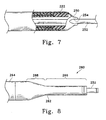
- Figure 7 shows a further variation of the invention in which the catheter device shown in any of the preceding Figures is covered with an outer tubing (250) which "necks down" distally of the terminal section (222) and fits tightly about micro-catheter (252).
- the outer covering (250) may be made of , e.g., a shrink-wrap material such as irradiated and oriented polyethylene, which has been shrunk onto the shaft of the catheter assembly.
- the variation shown in Figure 7 has one or more slits (254) which operate as "one-way” valves against the micro-catheter (252) outer surface. This valving region prevents the body fluids from flowing into the catheter yet allows fluids such as radio-opaque materials to flow outwardly.
- the outer covering (250) may extend proximally up the catheter as long as is convenient.
- FIG 8 shows still another variation (260) of the inventive guide catheter assembly.
- the micro-catheter (252) is shown extending from the distal end of the guide catheter (260).
- the terminal section (262) in this variation is quite extensive.
- the terminal section (262) has a narrow diameter section (264) and a papered section (268).
- the inner lumen of narrow diameter section (266) fits closely about the outer diameter of microcatheter (252), e.g., with a clearance of 0.002" (50.8 ⁇ m) or so.
- Radio-opaque materials may be ejected through the end of the catheter assembly in the annular space outside the micro-catheter (252).
- radio-opaque fluids may also be ejected through the hole to improve visibility of the vessel.
- the braid reinforced sections are only to be found proximal of the terminal section, e.g., beginning in the section (264).
Claims (9)
- Cathéter de guidage intravasculaire comprenant :dans lequel la dureté du matériau polymère dudit élément de tige terminal (102) est supérieure à celle du matériau polymère constituant la couche extérieure dudit élément de tige distal (104).une tige tubulaire allongée constituée par au moins deux éléments de tige tubulaires (102, 104, 106, 108, 110), ladite tige tubulaire allongée comprenant :a.) un élément de tige distal (104) constitué par un matériau polymère extérieur comportant une couche de renforcement tressée incorporée à l'intérieur de celui-ci et revêtue d'un matériau polymère lubrifiant intérieur, etb.) un élément de tige terminal (102) constitué par un matériau polymère, exempt de renforcement tressé, comportant une paroi et un conduit à travers celui-ci, et fixé audit élément de tige distal et disposé de façon distale vis-à-vis dudit élément de tige distal,
- Cathéter selon la revendication 1, dans lequel l'arbre allongé comprend de plus un élément tubulaire de milieu de tige principal (106) proximalement adjacent audit élément de tige distal (104) et comportant un revêtement extérieur comprenant un matériau plus dur que le matériau formant la couche de revêtement extérieure dudit élément de tige distal (104).
- Cathéter selon la revendication 2, dans lequel l'arbre allongé comprend de plus un élément de milieu de tige secondaire (108) proximalement adjacent audit élément de milieu de tige principal et comportant une couche polymère extérieure ayant une dureté supérieure à celle de la couche de revêtement extérieure dudit élément de milieu de tige principal (106).
- Cathéter selon la revendication 3, dans lequel l'arbre allongé comprend de plus un élément de tige proximal (110) proximalement adjacent audit élément de milieu de tige secondaire et comportant un revêtement extérieur plus dur que le revêtement extérieur de l'élément de milieu de tige secondaire (108).
- Cathéter selon la revendication 4, dans lequel la tresse s'étend de façon continue de l'élément de tige proximal (110) à l'extrémité distale de l'élément de tige distal (104).
- Cathéter selon la revendication 4, dans lequel chacun parmi l'élément de tige distal (104), l'élément tubulaire de milieu de tige principal (106), l'élément tubulaire de milieu de tige secondaire (108) et l'élément de tige proximal (110) contient une tresse qui n'est pas continue entre ces éléments.
- Cathéter selon l'une quelconque des revendications précédentes, dans lequel la tresse comprend un acier inoxydable.
- Cathéter selon l'une quelconque des revendications précédentes, dans lequel la tresse comprend un alliage superélastique.
- Cathéter selon l'une quelconque des revendications précédentes, dans lequel l'élément de tige terminal et l'élément de tige distal ont chacun des diamètres, et le diamètre de l'élément de tige terminal est inférieur au diamètre de l'élément de tige distal.
Applications Claiming Priority (3)
| Application Number | Priority Date | Filing Date | Title |
|---|---|---|---|
| US729237 | 1996-10-09 | ||
| US08/729,237 US5971975A (en) | 1996-10-09 | 1996-10-09 | Guide catheter with enhanced guidewire tracking |
| PCT/US1997/015850 WO1998015311A1 (fr) | 1996-10-09 | 1997-10-07 | Catheter-guide a poursuite amelioree par fil directeur |
Publications (2)
| Publication Number | Publication Date |
|---|---|
| EP0930910A1 EP0930910A1 (fr) | 1999-07-28 |
| EP0930910B1 true EP0930910B1 (fr) | 2004-01-14 |
Family
ID=24930144
Family Applications (1)
| Application Number | Title | Priority Date | Filing Date |
|---|---|---|---|
| EP97910708A Expired - Lifetime EP0930910B1 (fr) | 1996-10-09 | 1997-10-07 | Catheter-guide a poursuite amelioree par fil directeur |
Country Status (6)
| Country | Link |
|---|---|
| US (1) | US5971975A (fr) |
| EP (1) | EP0930910B1 (fr) |
| JP (1) | JP2001501846A (fr) |
| AU (1) | AU4800997A (fr) |
| DE (1) | DE69727238T2 (fr) |
| WO (1) | WO1998015311A1 (fr) |
Families Citing this family (231)
| Publication number | Priority date | Publication date | Assignee | Title |
|---|---|---|---|---|
| US20030069522A1 (en) | 1995-12-07 | 2003-04-10 | Jacobsen Stephen J. | Slotted medical device |
| US6251092B1 (en) * | 1997-12-30 | 2001-06-26 | Medtronic, Inc. | Deflectable guiding catheter |
| US6203505B1 (en) | 1998-06-05 | 2001-03-20 | Advanced Cardiovascular Systems, Inc. | Guidewires having a vapor deposited primer coat |
| US6245053B1 (en) * | 1998-11-09 | 2001-06-12 | Medtronic, Inc. | Soft tip guiding catheter and method of fabrication |
| US6591472B1 (en) * | 1998-12-08 | 2003-07-15 | Medtronic, Inc. | Multiple segment catheter and method of fabrication |
| US6355027B1 (en) * | 1999-06-09 | 2002-03-12 | Possis Medical, Inc. | Flexible microcatheter |
| US6398791B1 (en) * | 1999-06-11 | 2002-06-04 | Scimed Life Systems Inc | Variable composite sheath with interrupted sections |
| CA2378720A1 (fr) * | 1999-07-23 | 2001-02-01 | Tfx Medical Extrusion Products | Dispositif a catheter dote d'une tige multilumieres renforcee et son procede de fabrication |
| US6648874B2 (en) * | 2000-02-28 | 2003-11-18 | Scimed Life Systems, Inc. | Guide catheter with lubricious inner liner |
| US6500130B2 (en) | 2000-12-21 | 2002-12-31 | Scimed Life Systems, Inc. | Steerable guidewire |
| DE10105592A1 (de) | 2001-02-06 | 2002-08-08 | Achim Goepferich | Platzhalter zur Arzneistofffreigabe in der Stirnhöhle |
| WO2002083224A2 (fr) * | 2001-04-17 | 2002-10-24 | Salviac Limited | Catheter |
| US20090163946A1 (en) * | 2001-04-17 | 2009-06-25 | Salviac Limited | Catheter |
| US6716207B2 (en) * | 2001-05-22 | 2004-04-06 | Scimed Life Systems, Inc. | Torqueable and deflectable medical device shaft |
| DE20110121U1 (de) * | 2001-06-19 | 2002-12-05 | Braun Melsungen Ag | Katheter |
| US6776945B2 (en) * | 2001-07-03 | 2004-08-17 | Scimed Life Systems, Inc. | Medical device with extruded member having helical orientation |
| ES2274984T3 (es) | 2001-07-05 | 2007-06-01 | Precision Vascular Systems, Inc. | Dispositivo medico de punta blanda que puede someterse a torsion y metodo para conformarlo. |
| JP2003250901A (ja) * | 2002-02-28 | 2003-09-09 | Toray Ind Inc | X線造影性に優れた医療用チューブ |
| GB0205772D0 (en) * | 2002-03-12 | 2002-04-24 | Gill Steven S | Catheter |
| US20030199852A1 (en) * | 2002-04-23 | 2003-10-23 | Endobionics, Inc. | Attachment joints with polymer encapsulation |
| US7115134B2 (en) * | 2002-07-22 | 2006-10-03 | Chambers Technology, Llc. | Catheter with flexible tip and shape retention |
| JP4602080B2 (ja) | 2002-07-25 | 2010-12-22 | ボストン サイエンティフィック リミテッド | 人体構造内を進行する医療用具 |
| US7914467B2 (en) | 2002-07-25 | 2011-03-29 | Boston Scientific Scimed, Inc. | Tubular member having tapered transition for use in a medical device |
| US7004937B2 (en) * | 2002-07-31 | 2006-02-28 | Cryocor, Inc. | Wire reinforced articulation segment |
| US7309318B2 (en) * | 2002-09-18 | 2007-12-18 | Boston Scientific Scimed, Inc. | Flexible composite guidewire for intravascular catheter |
| US8317816B2 (en) | 2002-09-30 | 2012-11-27 | Acclarent, Inc. | Balloon catheters and methods for treating paranasal sinuses |
| US20110172644A1 (en) * | 2002-12-04 | 2011-07-14 | Zanoni Michael S | Multi layer coextruded catheter shaft |
| EP1435253B1 (fr) * | 2002-12-31 | 2007-01-17 | Abbott Laboratories Vascular Enterprises Limited | Cathéter avec partie plus flexible entre la tige et la pointe distale et procédé de fabrication |
| US8377035B2 (en) | 2003-01-17 | 2013-02-19 | Boston Scientific Scimed, Inc. | Unbalanced reinforcement members for medical device |
| US7169118B2 (en) | 2003-02-26 | 2007-01-30 | Scimed Life Systems, Inc. | Elongate medical device with distal cap |
| US8256428B2 (en) * | 2003-03-12 | 2012-09-04 | Biosense Webster, Inc. | Method for treating tissue |
| US7276062B2 (en) | 2003-03-12 | 2007-10-02 | Biosence Webster, Inc. | Deflectable catheter with hinge |
| US7001369B2 (en) | 2003-03-27 | 2006-02-21 | Scimed Life Systems, Inc. | Medical device |
| WO2004091710A1 (fr) | 2003-04-14 | 2004-10-28 | Cook Incorporated | Catheter/ gaine d'administration a large diametre |
| DK1872820T3 (en) | 2003-04-28 | 2015-09-07 | Cook Medical Technologies Llc | Flexible insertion sheath with varying durometer |
| EP2452648B1 (fr) | 2003-09-12 | 2016-02-10 | Vessix Vascular, Inc. | Système de remodelage et/ou de l'ablation excentrique sélectionnable de matériau athérosclérotique |
| US7771369B2 (en) * | 2003-12-05 | 2010-08-10 | Boston Scientific Scimed, Inc. | Guide catheter with removable support |
| US7824345B2 (en) | 2003-12-22 | 2010-11-02 | Boston Scientific Scimed, Inc. | Medical device with push force limiter |
| US7747314B2 (en) * | 2003-12-30 | 2010-06-29 | Boston Scientific Scimed, Inc. | Distal assembly for a medical device |
| US7559925B2 (en) | 2006-09-15 | 2009-07-14 | Acclarent Inc. | Methods and devices for facilitating visualization in a surgical environment |
| US20190314620A1 (en) | 2004-04-21 | 2019-10-17 | Acclarent, Inc. | Apparatus and methods for dilating and modifying ostia of paranasal sinuses and other intranasal or paranasal structures |
| US8932276B1 (en) | 2004-04-21 | 2015-01-13 | Acclarent, Inc. | Shapeable guide catheters and related methods |
| US7803150B2 (en) | 2004-04-21 | 2010-09-28 | Acclarent, Inc. | Devices, systems and methods useable for treating sinusitis |
| US7419497B2 (en) | 2004-04-21 | 2008-09-02 | Acclarent, Inc. | Methods for treating ethmoid disease |
| US20060063973A1 (en) | 2004-04-21 | 2006-03-23 | Acclarent, Inc. | Methods and apparatus for treating disorders of the ear, nose and throat |
| US10188413B1 (en) | 2004-04-21 | 2019-01-29 | Acclarent, Inc. | Deflectable guide catheters and related methods |
| US20070208252A1 (en) | 2004-04-21 | 2007-09-06 | Acclarent, Inc. | Systems and methods for performing image guided procedures within the ear, nose, throat and paranasal sinuses |
| US8864787B2 (en) | 2004-04-21 | 2014-10-21 | Acclarent, Inc. | Ethmoidotomy system and implantable spacer devices having therapeutic substance delivery capability for treatment of paranasal sinusitis |
| US8764729B2 (en) | 2004-04-21 | 2014-07-01 | Acclarent, Inc. | Frontal sinus spacer |
| US9089258B2 (en) | 2004-04-21 | 2015-07-28 | Acclarent, Inc. | Endoscopic methods and devices for transnasal procedures |
| US9351750B2 (en) | 2004-04-21 | 2016-05-31 | Acclarent, Inc. | Devices and methods for treating maxillary sinus disease |
| US7462175B2 (en) | 2004-04-21 | 2008-12-09 | Acclarent, Inc. | Devices, systems and methods for treating disorders of the ear, nose and throat |
| US9399121B2 (en) | 2004-04-21 | 2016-07-26 | Acclarent, Inc. | Systems and methods for transnasal dilation of passageways in the ear, nose or throat |
| US8894614B2 (en) | 2004-04-21 | 2014-11-25 | Acclarent, Inc. | Devices, systems and methods useable for treating frontal sinusitis |
| US9101384B2 (en) | 2004-04-21 | 2015-08-11 | Acclarent, Inc. | Devices, systems and methods for diagnosing and treating sinusitis and other disorders of the ears, Nose and/or throat |
| US20060004323A1 (en) | 2004-04-21 | 2006-01-05 | Exploramed Nc1, Inc. | Apparatus and methods for dilating and modifying ostia of paranasal sinuses and other intranasal or paranasal structures |
| US7654997B2 (en) | 2004-04-21 | 2010-02-02 | Acclarent, Inc. | Devices, systems and methods for diagnosing and treating sinusitus and other disorders of the ears, nose and/or throat |
| US20070167682A1 (en) | 2004-04-21 | 2007-07-19 | Acclarent, Inc. | Endoscopic methods and devices for transnasal procedures |
| US7361168B2 (en) | 2004-04-21 | 2008-04-22 | Acclarent, Inc. | Implantable device and methods for delivering drugs and other substances to treat sinusitis and other disorders |
| US8747389B2 (en) | 2004-04-21 | 2014-06-10 | Acclarent, Inc. | Systems for treating disorders of the ear, nose and throat |
| US8702626B1 (en) | 2004-04-21 | 2014-04-22 | Acclarent, Inc. | Guidewires for performing image guided procedures |
| US9554691B2 (en) | 2004-04-21 | 2017-01-31 | Acclarent, Inc. | Endoscopic methods and devices for transnasal procedures |
| US20060030835A1 (en) * | 2004-06-29 | 2006-02-09 | Sherman Darren R | Catheter shaft tubes and methods of making |
| US7166100B2 (en) * | 2004-06-29 | 2007-01-23 | Cordis Neurovascular, Inc. | Balloon catheter shaft design |
| US7850675B2 (en) * | 2004-07-20 | 2010-12-14 | Boston Scientific Scimed, Inc. | Reinforced venous access catheter |
| WO2006020044A1 (fr) * | 2004-07-21 | 2006-02-23 | Cook Incorporated | Gaine d’introduction et procede de fabrication de celle-ci |
| US20060144408A1 (en) * | 2004-07-23 | 2006-07-06 | Ferry Steven J | Micro-catheter device and method of using same |
| US9713730B2 (en) | 2004-09-10 | 2017-07-25 | Boston Scientific Scimed, Inc. | Apparatus and method for treatment of in-stent restenosis |
| US8396548B2 (en) | 2008-11-14 | 2013-03-12 | Vessix Vascular, Inc. | Selective drug delivery in a lumen |
| US7682352B2 (en) * | 2004-09-28 | 2010-03-23 | Medtronic Vascular, Inc. | Catheter with curved distal section having reinforcing strip and method of making same |
| US7632242B2 (en) | 2004-12-09 | 2009-12-15 | Boston Scientific Scimed, Inc. | Catheter including a compliant balloon |
| US7815599B2 (en) * | 2004-12-10 | 2010-10-19 | Boston Scientific Scimed, Inc. | Catheter having an ultra soft tip and methods for making the same |
| JP2006333966A (ja) * | 2005-05-31 | 2006-12-14 | Kaneka Corp | 塞栓コイルデリバリー用カテーテルチューブ |
| US8951225B2 (en) | 2005-06-10 | 2015-02-10 | Acclarent, Inc. | Catheters with non-removable guide members useable for treatment of sinusitis |
| US20070014945A1 (en) * | 2005-07-12 | 2007-01-18 | Boston Scientific Scimed, Inc. | Guidewire with varied lubricity |
| US9445784B2 (en) | 2005-09-22 | 2016-09-20 | Boston Scientific Scimed, Inc | Intravascular ultrasound catheter |
| US8114113B2 (en) | 2005-09-23 | 2012-02-14 | Acclarent, Inc. | Multi-conduit balloon catheter |
| US7850623B2 (en) | 2005-10-27 | 2010-12-14 | Boston Scientific Scimed, Inc. | Elongate medical device with continuous reinforcement member |
| US20070225680A1 (en) * | 2006-03-21 | 2007-09-27 | Medtronic Vascular, Inc. | Guiding catheter with chemically softened distal portion and method of making same |
| US8019435B2 (en) | 2006-05-02 | 2011-09-13 | Boston Scientific Scimed, Inc. | Control of arterial smooth muscle tone |
| US8190389B2 (en) | 2006-05-17 | 2012-05-29 | Acclarent, Inc. | Adapter for attaching electromagnetic image guidance components to a medical device |
| CA2663319A1 (fr) | 2006-09-13 | 2008-03-20 | Boston Scientific Limited | Fil-guide de franchissement |
| US9820688B2 (en) | 2006-09-15 | 2017-11-21 | Acclarent, Inc. | Sinus illumination lightwire device |
| CA2666661C (fr) | 2006-10-18 | 2015-01-20 | Minnow Medical, Inc. | Rayonnement radiofrequence accorde et caracterisation electrique des tissus pour traitement selectif de tissus cibles |
| WO2008049082A2 (fr) | 2006-10-18 | 2008-04-24 | Minnow Medical, Inc. | Induction d'effets souhaitables de température sur un tissu humain |
| WO2008049087A2 (fr) | 2006-10-18 | 2008-04-24 | Minnow Medical, Inc. | Système pour induire des effets thermiques désirables sur un tissu anatomique |
| JP5518481B2 (ja) | 2006-11-30 | 2014-06-11 | ウロヴァルヴ インコーポレイテッド | カテーテルを差し込むためのシステム及び方法 |
| US8556914B2 (en) | 2006-12-15 | 2013-10-15 | Boston Scientific Scimed, Inc. | Medical device including structure for crossing an occlusion in a vessel |
| US8439687B1 (en) | 2006-12-29 | 2013-05-14 | Acclarent, Inc. | Apparatus and method for simulated insertion and positioning of guidewares and other interventional devices |
| WO2008106480A1 (fr) * | 2007-03-01 | 2008-09-04 | Boston Scientific Scimed, Inc. | Gaine d'introducteur de microcathéter |
| US8118757B2 (en) | 2007-04-30 | 2012-02-21 | Acclarent, Inc. | Methods and devices for ostium measurement |
| US8485199B2 (en) | 2007-05-08 | 2013-07-16 | Acclarent, Inc. | Methods and devices for protecting nasal turbinate during surgery |
| US7914515B2 (en) * | 2007-07-18 | 2011-03-29 | St. Jude Medical, Atrial Fibrillation Division, Inc. | Catheter and introducer catheter having torque transfer layer and method of manufacture |
| US8409114B2 (en) | 2007-08-02 | 2013-04-02 | Boston Scientific Scimed, Inc. | Composite elongate medical device including distal tubular member |
| US8105246B2 (en) | 2007-08-03 | 2012-01-31 | Boston Scientific Scimed, Inc. | Elongate medical device having enhanced torque and methods thereof |
| US8821477B2 (en) | 2007-08-06 | 2014-09-02 | Boston Scientific Scimed, Inc. | Alternative micromachined structures |
| US9808595B2 (en) | 2007-08-07 | 2017-11-07 | Boston Scientific Scimed, Inc | Microfabricated catheter with improved bonding structure |
| US7841994B2 (en) | 2007-11-02 | 2010-11-30 | Boston Scientific Scimed, Inc. | Medical device for crossing an occlusion in a vessel |
| ITMI20072309A1 (it) * | 2007-12-10 | 2009-06-11 | N G C Medical S P A | Tubo presentante un diametro allargabile, particolarmente utilizzabile come tubo per introduttore vasale durante studi emodinamici ed interventi relativi. |
| US10206821B2 (en) | 2007-12-20 | 2019-02-19 | Acclarent, Inc. | Eustachian tube dilation balloon with ventilation path |
| US8431057B2 (en) | 2007-12-30 | 2013-04-30 | St. Jude Medical, Atrial Fibrillation Division, Inc. | Catheter shaft and method of its manufacture |
| US8182432B2 (en) | 2008-03-10 | 2012-05-22 | Acclarent, Inc. | Corewire design and construction for medical devices |
| US8376961B2 (en) | 2008-04-07 | 2013-02-19 | Boston Scientific Scimed, Inc. | Micromachined composite guidewire structure with anisotropic bending properties |
| US8096985B2 (en) | 2008-05-07 | 2012-01-17 | Guided Delivery Systems Inc. | Deflectable guide |
| US9011412B2 (en) | 2008-05-16 | 2015-04-21 | Ford Albritton, IV | Apparatus, system and method for manipulating a surgical catheter and working device with a single hand |
| ES2700863T3 (es) | 2008-07-30 | 2019-02-19 | Acclarent Inc | Dispositivos de localización del ostium paranasal |
| US8535243B2 (en) | 2008-09-10 | 2013-09-17 | Boston Scientific Scimed, Inc. | Medical devices and tapered tubular members for use in medical devices |
| WO2010033629A1 (fr) | 2008-09-18 | 2010-03-25 | Acclarent, Inc. | Procédés et appareil de traitement de troubles d'oto-rhino-laryngologie |
| WO2010056745A1 (fr) | 2008-11-17 | 2010-05-20 | Minnow Medical, Inc. | Accumulation sélective d’énergie avec ou sans connaissance de la topographie tissulaire |
| EP2376171B1 (fr) * | 2008-12-10 | 2018-04-25 | Microvention, Inc. | Microcathéter |
| US8795254B2 (en) | 2008-12-10 | 2014-08-05 | Boston Scientific Scimed, Inc. | Medical devices with a slotted tubular member having improved stress distribution |
| WO2010085456A1 (fr) | 2009-01-20 | 2010-07-29 | Guided Delivery Systems Inc. | Dispositifs de déploiement d'ancrage et procédés apparentés |
| US20100241155A1 (en) | 2009-03-20 | 2010-09-23 | Acclarent, Inc. | Guide system with suction |
| US7978742B1 (en) | 2010-03-24 | 2011-07-12 | Corning Incorporated | Methods for operating diode lasers |
| US8435290B2 (en) | 2009-03-31 | 2013-05-07 | Acclarent, Inc. | System and method for treatment of non-ventilating middle ear by providing a gas pathway through the nasopharynx |
| US20110060316A1 (en) * | 2009-09-04 | 2011-03-10 | Dicarlo Paul | Tipped Ribbon Integrated Guidewire |
| JP5013380B2 (ja) * | 2009-10-29 | 2012-08-29 | 朝日インテック株式会社 | 医療用チューブ、及び、これを用いたカテーテル |
| US8137293B2 (en) | 2009-11-17 | 2012-03-20 | Boston Scientific Scimed, Inc. | Guidewires including a porous nickel-titanium alloy |
| JP2013523282A (ja) | 2010-03-31 | 2013-06-17 | ボストン サイエンティフィック サイムド,インコーポレイテッド | 曲げ剛性プロファイルを有するガイドワイヤ |
| JP2013523318A (ja) | 2010-04-09 | 2013-06-17 | べシックス・バスキュラー・インコーポレイテッド | 組織の治療のための発電および制御の装置 |
| US9192790B2 (en) | 2010-04-14 | 2015-11-24 | Boston Scientific Scimed, Inc. | Focused ultrasonic renal denervation |
| US8473067B2 (en) | 2010-06-11 | 2013-06-25 | Boston Scientific Scimed, Inc. | Renal denervation and stimulation employing wireless vascular energy transfer arrangement |
| US9358365B2 (en) | 2010-07-30 | 2016-06-07 | Boston Scientific Scimed, Inc. | Precision electrode movement control for renal nerve ablation |
| US9408661B2 (en) | 2010-07-30 | 2016-08-09 | Patrick A. Haverkost | RF electrodes on multiple flexible wires for renal nerve ablation |
| US9463062B2 (en) | 2010-07-30 | 2016-10-11 | Boston Scientific Scimed, Inc. | Cooled conductive balloon RF catheter for renal nerve ablation |
| US9155589B2 (en) | 2010-07-30 | 2015-10-13 | Boston Scientific Scimed, Inc. | Sequential activation RF electrode set for renal nerve ablation |
| US9084609B2 (en) | 2010-07-30 | 2015-07-21 | Boston Scientific Scime, Inc. | Spiral balloon catheter for renal nerve ablation |
| US9155492B2 (en) | 2010-09-24 | 2015-10-13 | Acclarent, Inc. | Sinus illumination lightwire device |
| TWI556849B (zh) | 2010-10-21 | 2016-11-11 | 美敦力阿福盧森堡公司 | 用於腎臟神經協調的導管裝置 |
| US8974451B2 (en) | 2010-10-25 | 2015-03-10 | Boston Scientific Scimed, Inc. | Renal nerve ablation using conductive fluid jet and RF energy |
| US9220558B2 (en) | 2010-10-27 | 2015-12-29 | Boston Scientific Scimed, Inc. | RF renal denervation catheter with multiple independent electrodes |
| US9028485B2 (en) | 2010-11-15 | 2015-05-12 | Boston Scientific Scimed, Inc. | Self-expanding cooling electrode for renal nerve ablation |
| US9089350B2 (en) | 2010-11-16 | 2015-07-28 | Boston Scientific Scimed, Inc. | Renal denervation catheter with RF electrode and integral contrast dye injection arrangement |
| US9668811B2 (en) | 2010-11-16 | 2017-06-06 | Boston Scientific Scimed, Inc. | Minimally invasive access for renal nerve ablation |
| US9326751B2 (en) | 2010-11-17 | 2016-05-03 | Boston Scientific Scimed, Inc. | Catheter guidance of external energy for renal denervation |
| US9060761B2 (en) | 2010-11-18 | 2015-06-23 | Boston Scientific Scime, Inc. | Catheter-focused magnetic field induced renal nerve ablation |
| US9192435B2 (en) | 2010-11-22 | 2015-11-24 | Boston Scientific Scimed, Inc. | Renal denervation catheter with cooled RF electrode |
| US9023034B2 (en) | 2010-11-22 | 2015-05-05 | Boston Scientific Scimed, Inc. | Renal ablation electrode with force-activatable conduction apparatus |
| US20120157993A1 (en) | 2010-12-15 | 2012-06-21 | Jenson Mark L | Bipolar Off-Wall Electrode Device for Renal Nerve Ablation |
| US9220561B2 (en) | 2011-01-19 | 2015-12-29 | Boston Scientific Scimed, Inc. | Guide-compatible large-electrode catheter for renal nerve ablation with reduced arterial injury |
| WO2012106628A1 (fr) | 2011-02-04 | 2012-08-09 | Boston Scientific Scimed, Inc. | Fils guides et procédés pour fabriquer et utiliser ceux-ci |
| JP5110716B2 (ja) * | 2011-02-25 | 2012-12-26 | 朝日インテック株式会社 | カテーテル |
| US9072874B2 (en) | 2011-05-13 | 2015-07-07 | Boston Scientific Scimed, Inc. | Medical devices with a heat transfer region and a heat sink region and methods for manufacturing medical devices |
| WO2013013156A2 (fr) | 2011-07-20 | 2013-01-24 | Boston Scientific Scimed, Inc. | Dispositifs et procédés percutanés de visualisation, de ciblage et d'ablation de nerfs |
| EP2734264B1 (fr) | 2011-07-22 | 2018-11-21 | Boston Scientific Scimed, Inc. | Système de neuromodulation avec un élément de neuromodulation positionnable dans un guide hélicoïdal |
| WO2013055826A1 (fr) | 2011-10-10 | 2013-04-18 | Boston Scientific Scimed, Inc. | Dispositifs médicaux comprenant des électrodes d'ablation |
| US10085799B2 (en) | 2011-10-11 | 2018-10-02 | Boston Scientific Scimed, Inc. | Off-wall electrode device and methods for nerve modulation |
| US9420955B2 (en) | 2011-10-11 | 2016-08-23 | Boston Scientific Scimed, Inc. | Intravascular temperature monitoring system and method |
| US9364284B2 (en) | 2011-10-12 | 2016-06-14 | Boston Scientific Scimed, Inc. | Method of making an off-wall spacer cage |
| US9162046B2 (en) | 2011-10-18 | 2015-10-20 | Boston Scientific Scimed, Inc. | Deflectable medical devices |
| US9079000B2 (en) | 2011-10-18 | 2015-07-14 | Boston Scientific Scimed, Inc. | Integrated crossing balloon catheter |
| CN108095821B (zh) | 2011-11-08 | 2021-05-25 | 波士顿科学西美德公司 | 孔部肾神经消融 |
| WO2013074813A1 (fr) | 2011-11-15 | 2013-05-23 | Boston Scientific Scimed, Inc. | Dispositif et procédés pour surveiller la modulation nerveuse rénale |
| US9119632B2 (en) | 2011-11-21 | 2015-09-01 | Boston Scientific Scimed, Inc. | Deflectable renal nerve ablation catheter |
| US9265969B2 (en) | 2011-12-21 | 2016-02-23 | Cardiac Pacemakers, Inc. | Methods for modulating cell function |
| AU2012358143B2 (en) | 2011-12-23 | 2015-06-11 | Boston Scientific Scimed, Inc. | Expandable balloon or an electrode pad with a heat sensing device |
| US9433760B2 (en) | 2011-12-28 | 2016-09-06 | Boston Scientific Scimed, Inc. | Device and methods for nerve modulation using a novel ablation catheter with polymeric ablative elements |
| US9050106B2 (en) | 2011-12-29 | 2015-06-09 | Boston Scientific Scimed, Inc. | Off-wall electrode device and methods for nerve modulation |
| CN102553046A (zh) * | 2012-02-23 | 2012-07-11 | 苏州伟康医疗器械有限公司 | 一次性使用口鼻吸氧管 |
| US9072624B2 (en) | 2012-02-23 | 2015-07-07 | Covidien Lp | Luminal stenting |
| US9981113B2 (en) * | 2012-03-14 | 2018-05-29 | Access Scientific, Llc | Flexible medical article and method of making the same |
| WO2013138519A1 (fr) | 2012-03-14 | 2013-09-19 | Access Scientific, Llc | Article médical flexible et son procédé de fabrication |
| US9717554B2 (en) | 2012-03-26 | 2017-08-01 | Biosense Webster (Israel) Ltd. | Catheter with composite construction |
| US10660703B2 (en) | 2012-05-08 | 2020-05-26 | Boston Scientific Scimed, Inc. | Renal nerve modulation devices |
| US10639099B2 (en) | 2012-05-25 | 2020-05-05 | Biosense Webster (Israel), Ltd. | Catheter having a distal section with spring sections for biased deflection |
| CN104540465A (zh) | 2012-08-24 | 2015-04-22 | 波士顿科学西美德公司 | 带有含单独微孔隙区域的球囊的血管内导管 |
| WO2014043687A2 (fr) | 2012-09-17 | 2014-03-20 | Boston Scientific Scimed, Inc. | Système et procédé d'électrode à positionnement automatique pour une modulation de nerf rénal |
| WO2014047454A2 (fr) | 2012-09-21 | 2014-03-27 | Boston Scientific Scimed, Inc. | Cathéter d'ablation par ultrasons à refroidissement automatique |
| WO2014047411A1 (fr) | 2012-09-21 | 2014-03-27 | Boston Scientific Scimed, Inc. | Système de modulation des nerfs et blocage des nerfs par gradient thermique inoffensif |
| JP6074051B2 (ja) | 2012-10-10 | 2017-02-01 | ボストン サイエンティフィック サイムド,インコーポレイテッドBoston Scientific Scimed,Inc. | 血管内神経変調システム及び医療用デバイス |
| US9044575B2 (en) | 2012-10-22 | 2015-06-02 | Medtronic Adrian Luxembourg S.a.r.l. | Catheters with enhanced flexibility and associated devices, systems, and methods |
| WO2014143571A1 (fr) | 2013-03-11 | 2014-09-18 | Boston Scientific Scimed, Inc. | Dispositifs médicaux pour moduler des nerfs |
| WO2014163987A1 (fr) | 2013-03-11 | 2014-10-09 | Boston Scientific Scimed, Inc. | Dispositifs médicaux pour la modulation des nerfs |
| US9808311B2 (en) | 2013-03-13 | 2017-11-07 | Boston Scientific Scimed, Inc. | Deflectable medical devices |
| US9827039B2 (en) | 2013-03-15 | 2017-11-28 | Boston Scientific Scimed, Inc. | Methods and apparatuses for remodeling tissue of or adjacent to a body passage |
| US9629684B2 (en) | 2013-03-15 | 2017-04-25 | Acclarent, Inc. | Apparatus and method for treatment of ethmoid sinusitis |
| CN105228546B (zh) | 2013-03-15 | 2017-11-14 | 波士顿科学国际有限公司 | 利用阻抗补偿的用于治疗高血压的医疗器械和方法 |
| US9433437B2 (en) | 2013-03-15 | 2016-09-06 | Acclarent, Inc. | Apparatus and method for treatment of ethmoid sinusitis |
| US10265122B2 (en) | 2013-03-15 | 2019-04-23 | Boston Scientific Scimed, Inc. | Nerve ablation devices and related methods of use |
| EP2996754B1 (fr) | 2013-05-18 | 2023-04-26 | Medtronic Ardian Luxembourg S.à.r.l. | Sondes de neuromodulation comportant une tige, pour une souplesse et une commande améliorées, et dispositifs et systèmes associés |
| JP2016524949A (ja) | 2013-06-21 | 2016-08-22 | ボストン サイエンティフィック サイムド,インコーポレイテッドBoston Scientific Scimed,Inc. | 回転可能シャフトを有する腎神経アブレーション用医療装置 |
| EP3010437A1 (fr) | 2013-06-21 | 2016-04-27 | Boston Scientific Scimed, Inc. | Cathéter à ballonnet pour énervation rénale à support d'électrode accompagnant |
| US9707036B2 (en) | 2013-06-25 | 2017-07-18 | Boston Scientific Scimed, Inc. | Devices and methods for nerve modulation using localized indifferent electrodes |
| AU2014284558B2 (en) | 2013-07-01 | 2017-08-17 | Boston Scientific Scimed, Inc. | Medical devices for renal nerve ablation |
| US10660698B2 (en) | 2013-07-11 | 2020-05-26 | Boston Scientific Scimed, Inc. | Devices and methods for nerve modulation |
| EP3019106A1 (fr) | 2013-07-11 | 2016-05-18 | Boston Scientific Scimed, Inc. | Dispositif médical équipé d'ensembles électrodes extensibles |
| EP3049007B1 (fr) | 2013-07-19 | 2019-06-12 | Boston Scientific Scimed, Inc. | Ballonnet de dénervation rénale à électrode bipolaire en spirale |
| JP6122217B2 (ja) | 2013-07-22 | 2017-04-26 | ボストン サイエンティフィック サイムド,インコーポレイテッドBoston Scientific Scimed,Inc. | 腎神経アブレーション用医療器具 |
| WO2015013205A1 (fr) | 2013-07-22 | 2015-01-29 | Boston Scientific Scimed, Inc. | Dispositifs médicaux pour l'ablation de nerfs rénaux |
| CN105473093B (zh) | 2013-08-22 | 2019-02-05 | 波士顿科学国际有限公司 | 具有至肾神经调制球囊的改善的粘附力的柔性电路 |
| US9782186B2 (en) | 2013-08-27 | 2017-10-10 | Covidien Lp | Vascular intervention system |
| US10045867B2 (en) | 2013-08-27 | 2018-08-14 | Covidien Lp | Delivery of medical devices |
| CN105555218B (zh) | 2013-09-04 | 2019-01-15 | 波士顿科学国际有限公司 | 具有冲洗和冷却能力的射频(rf)球囊导管 |
| EP3043733A1 (fr) | 2013-09-13 | 2016-07-20 | Boston Scientific Scimed, Inc. | Ballonnet d'ablation à couche de revêtement déposée en phase vapeur |
| EP3052176B1 (fr) * | 2013-09-30 | 2019-05-15 | Biocardia, Inc. | Cathéter d'administration radiale et endocavitaire |
| US11246654B2 (en) | 2013-10-14 | 2022-02-15 | Boston Scientific Scimed, Inc. | Flexible renal nerve ablation devices and related methods of use and manufacture |
| US9687166B2 (en) | 2013-10-14 | 2017-06-27 | Boston Scientific Scimed, Inc. | High resolution cardiac mapping electrode array catheter |
| WO2015057584A1 (fr) | 2013-10-15 | 2015-04-23 | Boston Scientific Scimed, Inc. | Ballonnet de dispositif médical |
| US9770606B2 (en) | 2013-10-15 | 2017-09-26 | Boston Scientific Scimed, Inc. | Ultrasound ablation catheter with cooling infusion and centering basket |
| WO2015057961A1 (fr) | 2013-10-18 | 2015-04-23 | Boston Scientific Scimed, Inc. | Cathéters à ballonnet avec fils conducteurs flexibles et procédés d'utilisation et de fabrication connexes |
| WO2015061457A1 (fr) | 2013-10-25 | 2015-04-30 | Boston Scientific Scimed, Inc. | Thermocouple intégré dans un circuit souple d'énervation |
| US20150174364A1 (en) * | 2013-12-19 | 2015-06-25 | Smiths Medical Asd, Inc. | Soft tip catheter |
| WO2015103617A1 (fr) | 2014-01-06 | 2015-07-09 | Boston Scientific Scimed, Inc. | Ensemble circuit souple résistant aux déchirures |
| EP4253024A3 (fr) | 2014-01-27 | 2023-12-27 | Medtronic Ireland Manufacturing Unlimited Company | Cathéters de neuromodulation ayant des éléments de neuromodulation enveloppés et dispositifs |
| US11000679B2 (en) | 2014-02-04 | 2021-05-11 | Boston Scientific Scimed, Inc. | Balloon protection and rewrapping devices and related methods of use |
| EP3102136B1 (fr) | 2014-02-04 | 2018-06-27 | Boston Scientific Scimed, Inc. | Variante de placement de capteurs thermiques sur une électrode bipolaire |
| US9901706B2 (en) | 2014-04-11 | 2018-02-27 | Boston Scientific Scimed, Inc. | Catheters and catheter shafts |
| US10736690B2 (en) | 2014-04-24 | 2020-08-11 | Medtronic Ardian Luxembourg S.A.R.L. | Neuromodulation catheters and associated systems and methods |
| US9636477B2 (en) | 2014-10-09 | 2017-05-02 | Vascular Solutions, Inc. | Catheter |
| EP4292551A3 (fr) | 2015-03-05 | 2024-01-31 | Ancora Heart, Inc. | Dispositifs de visualisation et de détermination de profondeur de pénétration dans un tissu cardiaque |
| US10357631B2 (en) | 2015-05-29 | 2019-07-23 | Covidien Lp | Catheter with tapering outer diameter |
| US11219740B2 (en) | 2015-05-29 | 2022-01-11 | Covidien Lp | Catheter including tapering coil member |
| JP6426068B2 (ja) * | 2015-08-10 | 2018-11-21 | 朝日インテック株式会社 | カテーテル及びバルーンカテーテル |
| US11351048B2 (en) | 2015-11-16 | 2022-06-07 | Boston Scientific Scimed, Inc. | Stent delivery systems with a reinforced deployment sheath |
| US10582914B2 (en) | 2016-01-15 | 2020-03-10 | Covidien Lp | Navigable endobronchial tool to access tissue outside a bronchus |
| JP2019521723A (ja) | 2016-05-26 | 2019-08-08 | メリット・メディカル・システムズ・インコーポレイテッドMerit Medical Systems,Inc. | 拡張可能導入器アセンブリ |
| US10376396B2 (en) | 2017-01-19 | 2019-08-13 | Covidien Lp | Coupling units for medical device delivery systems |
| US10926060B2 (en) | 2017-03-02 | 2021-02-23 | Covidien Lp | Flexible tip catheter |
| US10537710B2 (en) | 2017-04-20 | 2020-01-21 | Covidien Lp | Catheter including an inner liner with a flexible distal section |
| US10238834B2 (en) | 2017-08-25 | 2019-03-26 | Teleflex Innovations S.À.R.L. | Catheter |
| US10786377B2 (en) | 2018-04-12 | 2020-09-29 | Covidien Lp | Medical device delivery |
| US11071637B2 (en) | 2018-04-12 | 2021-07-27 | Covidien Lp | Medical device delivery |
| US11413176B2 (en) | 2018-04-12 | 2022-08-16 | Covidien Lp | Medical device delivery |
| US11123209B2 (en) | 2018-04-12 | 2021-09-21 | Covidien Lp | Medical device delivery |
| US10953195B2 (en) | 2018-06-01 | 2021-03-23 | Covidien Lp | Flexible tip catheter |
| JP2022515796A (ja) * | 2018-12-19 | 2022-02-22 | 深▲セン▼市▲業▼聚▲實▼▲業▼有限公司 | 新型マイクロカテーテル |
| US11413174B2 (en) | 2019-06-26 | 2022-08-16 | Covidien Lp | Core assembly for medical device delivery systems |
| US11471650B2 (en) | 2019-09-20 | 2022-10-18 | Biosense Webster (Israel) Ltd. | Mechanism for manipulating a puller wire |
| EP3982850B1 (fr) * | 2019-10-30 | 2024-04-17 | Boston Scientific Scimed, Inc. | Dispositif cathéter endoscopique |
| US20220008692A1 (en) * | 2020-07-07 | 2022-01-13 | Covidien Lp | Catheter including variable density structural support member |
| US11944558B2 (en) | 2021-08-05 | 2024-04-02 | Covidien Lp | Medical device delivery devices, systems, and methods |
Family Cites Families (47)
| Publication number | Priority date | Publication date | Assignee | Title |
|---|---|---|---|---|
| US243396A (en) * | 1881-06-28 | Edwaed peaeee | ||
| US2211975A (en) * | 1937-03-16 | 1940-08-20 | Floyd C Hendrickson | Catheter |
| US2437542A (en) * | 1944-05-05 | 1948-03-09 | American Catheter Corp | Catheter-type instrument |
| US3174851A (en) * | 1961-12-01 | 1965-03-23 | William J Buehler | Nickel-base alloys |
| US3416531A (en) * | 1964-01-02 | 1968-12-17 | Edwards Miles Lowell | Catheter |
| US3351463A (en) * | 1965-08-20 | 1967-11-07 | Alexander G Rozner | High strength nickel-base alloys |
| US3753700A (en) * | 1970-07-02 | 1973-08-21 | Raychem Corp | Heat recoverable alloy |
| US3757768A (en) * | 1972-04-07 | 1973-09-11 | Medical Evaluation Devices And | Manipulable spring guide-catheter and tube for intravenous feeding |
| US3924632A (en) * | 1972-12-07 | 1975-12-09 | William A Cook | Fiber glass reinforced catheter |
| US4657024A (en) * | 1980-02-04 | 1987-04-14 | Teleflex Incorporated | Medical-surgical catheter |
| US4430083A (en) * | 1981-03-06 | 1984-02-07 | American Hospital Supply Corporation | Infusion catheter |
| US4425919A (en) * | 1981-07-27 | 1984-01-17 | Raychem Corporation | Torque transmitting catheter apparatus |
| JPS5886129A (ja) * | 1981-11-17 | 1983-05-23 | 旭光学工業株式会社 | 内視鏡の可撓管及びその製造方法 |
| US4516972A (en) * | 1982-01-28 | 1985-05-14 | Advanced Cardiovascular Systems, Inc. | Guiding catheter and method of manufacture |
| US4484586A (en) * | 1982-05-27 | 1984-11-27 | Berkley & Company, Inc. | Hollow conductive medical tubing |
| JPS5936A (ja) * | 1982-06-24 | 1984-01-05 | オリンパス光学工業株式会社 | 内視鏡の可撓管 |
| US4806182A (en) * | 1985-10-15 | 1989-02-21 | Schneider-Shiley (U.S.A.) Inc. | Method of bonding a hub to a Teflon-lined catheter body |
| JPS62139626A (ja) * | 1985-12-13 | 1987-06-23 | オリンパス光学工業株式会社 | 内視鏡用可撓管 |
| JPH025799Y2 (fr) * | 1986-02-07 | 1990-02-13 | ||
| US4676229A (en) * | 1986-04-09 | 1987-06-30 | Welch Allyn, Inc. | Biopsy channel for an endoscope |
| US4739768B2 (en) * | 1986-06-02 | 1995-10-24 | Target Therapeutics Inc | Catheter for guide-wire tracking |
| FR2608037A1 (fr) * | 1986-12-10 | 1988-06-17 | Lenck Lucien | Methode d'intubation destinee a permettre la transplantation de l'oeuf ou de la matiere embryonnaire, et moyens pour sa mise en oeuvre |
| FR2613231A1 (fr) * | 1987-04-06 | 1988-10-07 | Nivarox Sa | Sonde medicale destinee en particulier a l'execution d'interventions a l'interieur du corps humain ou animal |
| US4981478A (en) * | 1988-09-06 | 1991-01-01 | Advanced Cardiovascular Systems | Composite vascular catheter |
| US5037404A (en) * | 1988-11-14 | 1991-08-06 | Cordis Corporation | Catheter having sections of variable torsion characteristics |
| US4985022A (en) * | 1988-11-23 | 1991-01-15 | Med Institute, Inc. | Catheter having durable and flexible segments |
| JPH02283346A (ja) * | 1989-04-25 | 1990-11-20 | Olympus Optical Co Ltd | 内視鏡用可撓管 |
| JPH07110270B2 (ja) * | 1989-06-21 | 1995-11-29 | オリンパス光学工業株式会社 | 内視鏡可撓管用外皮 |
| US5248305A (en) * | 1989-08-04 | 1993-09-28 | Cordis Corporation | Extruded tubing and catheters having helical liquid crystal fibrils |
| EP0421650A1 (fr) * | 1989-10-06 | 1991-04-10 | C.R. Bard, Inc. | Construction de cathéter à film laminé multicouche enroulé |
| US5176660A (en) * | 1989-10-23 | 1993-01-05 | Cordis Corporation | Catheter having reinforcing strands |
| US5057092A (en) * | 1990-04-04 | 1991-10-15 | Webster Wilton W Jr | Braided catheter with low modulus warp |
| US5180376A (en) * | 1990-05-01 | 1993-01-19 | Cathco, Inc. | Non-buckling thin-walled sheath for the percutaneous insertion of intraluminal catheters |
| US5217482A (en) * | 1990-08-28 | 1993-06-08 | Scimed Life Systems, Inc. | Balloon catheter with distal guide wire lumen |
| US5178158A (en) * | 1990-10-29 | 1993-01-12 | Boston Scientific Corporation | Convertible guidewire-catheter with soft tip |
| US5222949A (en) * | 1991-07-23 | 1993-06-29 | Intermed, Inc. | Flexible, noncollapsible catheter tube with hard and soft regions |
| JPH05220225A (ja) * | 1991-08-26 | 1993-08-31 | Terumo Corp | カテーテル |
| JPH0556910A (ja) * | 1991-08-29 | 1993-03-09 | Olympus Optical Co Ltd | 管状挿入具 |
| EP0605615A1 (fr) * | 1991-09-26 | 1994-07-13 | Medtronic, Inc. | Catheter comportant un tube interieur en ressort enroule |
| AU3666993A (en) * | 1992-02-13 | 1993-09-03 | Navarre Biomedical, Ltd. | Kink resistant tubing apparatus |
| FR2692789B1 (fr) * | 1992-06-26 | 1999-09-17 | Vygon | Sonde a embout rapporte. |
| US5531721A (en) * | 1992-07-02 | 1996-07-02 | Scimed Life Systems, Inc. | Multiple member intravascular guide catheter |
| US5313967A (en) * | 1992-07-24 | 1994-05-24 | Medtronic, Inc. | Helical guidewire |
| JP3310031B2 (ja) * | 1992-10-23 | 2002-07-29 | テルモ株式会社 | カテーテルチューブ |
| US5405338A (en) * | 1993-08-19 | 1995-04-11 | Cordis Corporation | Helically wound catheters |
| NL9301642A (nl) * | 1993-09-22 | 1995-04-18 | Cordis Europ | Microcatheter. |
| JPH09507399A (ja) * | 1993-11-12 | 1997-07-29 | マイクロ インターベンショナル システムズ | 直径が小さく、かつトルクが高いカテーテル |
-
1996
- 1996-10-09 US US08/729,237 patent/US5971975A/en not_active Expired - Lifetime
-
1997
- 1997-10-07 DE DE69727238T patent/DE69727238T2/de not_active Expired - Lifetime
- 1997-10-07 WO PCT/US1997/015850 patent/WO1998015311A1/fr active IP Right Grant
- 1997-10-07 EP EP97910708A patent/EP0930910B1/fr not_active Expired - Lifetime
- 1997-10-07 AU AU48009/97A patent/AU4800997A/en not_active Abandoned
- 1997-10-07 JP JP10517520A patent/JP2001501846A/ja active Pending
Also Published As
| Publication number | Publication date |
|---|---|
| WO1998015311A1 (fr) | 1998-04-16 |
| AU4800997A (en) | 1998-05-05 |
| EP0930910A1 (fr) | 1999-07-28 |
| US5971975A (en) | 1999-10-26 |
| JP2001501846A (ja) | 2001-02-13 |
| DE69727238D1 (de) | 2004-02-19 |
| DE69727238T2 (de) | 2004-11-25 |
Similar Documents
| Publication | Publication Date | Title |
|---|---|---|
| EP0930910B1 (fr) | Catheter-guide a poursuite amelioree par fil directeur | |
| US6165163A (en) | Soft-tip performance braided catheter | |
| US5951539A (en) | Optimized high performance multiple coil spiral-wound vascular catheter | |
| US6824553B1 (en) | High performance braided catheter | |
| US6053903A (en) | High performance spiral-wound catheter | |
| US5891112A (en) | High performance superelastic alloy braid reinforced catheter | |
| US6143013A (en) | High performance braided catheter | |
| US6152912A (en) | Optimized high performance spiral-wound vascular catheter | |
| US5702373A (en) | Composite super-elastic alloy braid reinforced catheter | |
| EP1019130B1 (fr) | Cathéter d'apport vasculaire périphérique | |
| US6159187A (en) | Reinforced catheter with a formable distal tip | |
| EP0810003B1 (fr) | Cathéter tressé résistant au tortillement à trous latérales distales | |
| EP0717643B1 (fr) | Catheter dote d'une extremite distale resistante au vrillage | |
| US5599326A (en) | Catheter with multi-layer section | |
| US6090099A (en) | Multi-layer distal catheter section |
Legal Events
| Date | Code | Title | Description |
|---|---|---|---|
| PUAI | Public reference made under article 153(3) epc to a published international application that has entered the european phase |
Free format text: ORIGINAL CODE: 0009012 |
|
| 17P | Request for examination filed |
Effective date: 19990416 |
|
| AK | Designated contracting states |
Kind code of ref document: A1 Designated state(s): DE DK FR GB IE NL |
|
| 17Q | First examination report despatched |
Effective date: 20020923 |
|
| GRAP | Despatch of communication of intention to grant a patent |
Free format text: ORIGINAL CODE: EPIDOSNIGR1 |
|
| GRAS | Grant fee paid |
Free format text: ORIGINAL CODE: EPIDOSNIGR3 |
|
| GRAA | (expected) grant |
Free format text: ORIGINAL CODE: 0009210 |
|
| AK | Designated contracting states |
Kind code of ref document: B1 Designated state(s): DE DK FR GB IE NL |
|
| REG | Reference to a national code |
Ref country code: GB Ref legal event code: FG4D |
|
| REG | Reference to a national code |
Ref country code: IE Ref legal event code: FG4D |
|
| REF | Corresponds to: |
Ref document number: 69727238 Country of ref document: DE Date of ref document: 20040219 Kind code of ref document: P |
|
| PG25 | Lapsed in a contracting state [announced via postgrant information from national office to epo] |
Ref country code: DK Free format text: LAPSE BECAUSE OF FAILURE TO SUBMIT A TRANSLATION OF THE DESCRIPTION OR TO PAY THE FEE WITHIN THE PRESCRIBED TIME-LIMIT Effective date: 20040414 |
|
| ET | Fr: translation filed | ||
| PLBE | No opposition filed within time limit |
Free format text: ORIGINAL CODE: 0009261 |
|
| STAA | Information on the status of an ep patent application or granted ep patent |
Free format text: STATUS: NO OPPOSITION FILED WITHIN TIME LIMIT |
|
| 26N | No opposition filed |
Effective date: 20041015 |
|
| PGFP | Annual fee paid to national office [announced via postgrant information from national office to epo] |
Ref country code: NL Payment date: 20070920 Year of fee payment: 11 |
|
| NLV4 | Nl: lapsed or anulled due to non-payment of the annual fee |
Effective date: 20090501 |
|
| PG25 | Lapsed in a contracting state [announced via postgrant information from national office to epo] |
Ref country code: NL Free format text: LAPSE BECAUSE OF NON-PAYMENT OF DUE FEES Effective date: 20090501 |
|
| REG | Reference to a national code |
Ref country code: DE Ref legal event code: R082 Ref document number: 69727238 Country of ref document: DE Representative=s name: VOSSIUS & PARTNER PATENTANWAELTE RECHTSANWAELT, DE |
|
| REG | Reference to a national code |
Ref country code: FR Ref legal event code: PLFP Year of fee payment: 20 |
|
| PGFP | Annual fee paid to national office [announced via postgrant information from national office to epo] |
Ref country code: FR Payment date: 20160919 Year of fee payment: 20 |
|
| PGFP | Annual fee paid to national office [announced via postgrant information from national office to epo] |
Ref country code: DE Payment date: 20161004 Year of fee payment: 20 Ref country code: GB Payment date: 20161005 Year of fee payment: 20 Ref country code: IE Payment date: 20161010 Year of fee payment: 20 |
|
| REG | Reference to a national code |
Ref country code: DE Ref legal event code: R071 Ref document number: 69727238 Country of ref document: DE |
|
| REG | Reference to a national code |
Ref country code: GB Ref legal event code: PE20 Expiry date: 20171006 |
|
| REG | Reference to a national code |
Ref country code: IE Ref legal event code: MK9A |
|
| PG25 | Lapsed in a contracting state [announced via postgrant information from national office to epo] |
Ref country code: GB Free format text: LAPSE BECAUSE OF EXPIRATION OF PROTECTION Effective date: 20171006 Ref country code: IE Free format text: LAPSE BECAUSE OF EXPIRATION OF PROTECTION Effective date: 20171007 |