US7276062B2 - Deflectable catheter with hinge - Google Patents
Deflectable catheter with hinge Download PDFInfo
- Publication number
- US7276062B2 US7276062B2 US10/386,868 US38686803A US7276062B2 US 7276062 B2 US7276062 B2 US 7276062B2 US 38686803 A US38686803 A US 38686803A US 7276062 B2 US7276062 B2 US 7276062B2
- Authority
- US
- United States
- Prior art keywords
- distal
- hinge
- shaft
- catheter
- proximal
- Prior art date
- Legal status (The legal status is an assumption and is not a legal conclusion. Google has not performed a legal analysis and makes no representation as to the accuracy of the status listed.)
- Expired - Lifetime
Links
Images


Classifications
-
- A—HUMAN NECESSITIES
- A61—MEDICAL OR VETERINARY SCIENCE; HYGIENE
- A61M—DEVICES FOR INTRODUCING MEDIA INTO, OR ONTO, THE BODY; DEVICES FOR TRANSDUCING BODY MEDIA OR FOR TAKING MEDIA FROM THE BODY; DEVICES FOR PRODUCING OR ENDING SLEEP OR STUPOR
- A61M25/00—Catheters; Hollow probes
- A61M25/01—Introducing, guiding, advancing, emplacing or holding catheters
- A61M25/0105—Steering means as part of the catheter or advancing means; Markers for positioning
- A61M25/0133—Tip steering devices
- A61M25/0147—Tip steering devices with movable mechanical means, e.g. pull wires
-
- A—HUMAN NECESSITIES
- A61—MEDICAL OR VETERINARY SCIENCE; HYGIENE
- A61B—DIAGNOSIS; SURGERY; IDENTIFICATION
- A61B18/00—Surgical instruments, devices or methods for transferring non-mechanical forms of energy to or from the body
- A61B18/04—Surgical instruments, devices or methods for transferring non-mechanical forms of energy to or from the body by heating
- A61B18/12—Surgical instruments, devices or methods for transferring non-mechanical forms of energy to or from the body by heating by passing a current through the tissue to be heated, e.g. high-frequency current
- A61B18/14—Probes or electrodes therefor
- A61B18/1492—Probes or electrodes therefor having a flexible, catheter-like structure, e.g. for heart ablation
-
- A—HUMAN NECESSITIES
- A61—MEDICAL OR VETERINARY SCIENCE; HYGIENE
- A61B—DIAGNOSIS; SURGERY; IDENTIFICATION
- A61B5/00—Measuring for diagnostic purposes; Identification of persons
- A61B5/68—Arrangements of detecting, measuring or recording means, e.g. sensors, in relation to patient
- A61B5/6846—Arrangements of detecting, measuring or recording means, e.g. sensors, in relation to patient specially adapted to be brought in contact with an internal body part, i.e. invasive
- A61B5/6847—Arrangements of detecting, measuring or recording means, e.g. sensors, in relation to patient specially adapted to be brought in contact with an internal body part, i.e. invasive mounted on an invasive device
- A61B5/6852—Catheters
-
- A—HUMAN NECESSITIES
- A61—MEDICAL OR VETERINARY SCIENCE; HYGIENE
- A61M—DEVICES FOR INTRODUCING MEDIA INTO, OR ONTO, THE BODY; DEVICES FOR TRANSDUCING BODY MEDIA OR FOR TAKING MEDIA FROM THE BODY; DEVICES FOR PRODUCING OR ENDING SLEEP OR STUPOR
- A61M25/00—Catheters; Hollow probes
- A61M25/0043—Catheters; Hollow probes characterised by structural features
- A61M25/005—Catheters; Hollow probes characterised by structural features with embedded materials for reinforcement, e.g. wires, coils, braids
-
- A—HUMAN NECESSITIES
- A61—MEDICAL OR VETERINARY SCIENCE; HYGIENE
- A61M—DEVICES FOR INTRODUCING MEDIA INTO, OR ONTO, THE BODY; DEVICES FOR TRANSDUCING BODY MEDIA OR FOR TAKING MEDIA FROM THE BODY; DEVICES FOR PRODUCING OR ENDING SLEEP OR STUPOR
- A61M25/00—Catheters; Hollow probes
- A61M25/01—Introducing, guiding, advancing, emplacing or holding catheters
- A61M25/0105—Steering means as part of the catheter or advancing means; Markers for positioning
- A61M25/0133—Tip steering devices
- A61M25/0136—Handles therefor
-
- A—HUMAN NECESSITIES
- A61—MEDICAL OR VETERINARY SCIENCE; HYGIENE
- A61M—DEVICES FOR INTRODUCING MEDIA INTO, OR ONTO, THE BODY; DEVICES FOR TRANSDUCING BODY MEDIA OR FOR TAKING MEDIA FROM THE BODY; DEVICES FOR PRODUCING OR ENDING SLEEP OR STUPOR
- A61M25/00—Catheters; Hollow probes
- A61M25/01—Introducing, guiding, advancing, emplacing or holding catheters
- A61M25/0105—Steering means as part of the catheter or advancing means; Markers for positioning
- A61M25/0133—Tip steering devices
- A61M25/0138—Tip steering devices having flexible regions as a result of weakened outer material, e.g. slots, slits, cuts, joints or coils
-
- A—HUMAN NECESSITIES
- A61—MEDICAL OR VETERINARY SCIENCE; HYGIENE
- A61B—DIAGNOSIS; SURGERY; IDENTIFICATION
- A61B18/00—Surgical instruments, devices or methods for transferring non-mechanical forms of energy to or from the body
- A61B2018/00005—Cooling or heating of the probe or tissue immediately surrounding the probe
- A61B2018/00011—Cooling or heating of the probe or tissue immediately surrounding the probe with fluids
-
- A—HUMAN NECESSITIES
- A61—MEDICAL OR VETERINARY SCIENCE; HYGIENE
- A61B—DIAGNOSIS; SURGERY; IDENTIFICATION
- A61B18/00—Surgical instruments, devices or methods for transferring non-mechanical forms of energy to or from the body
- A61B2018/00315—Surgical instruments, devices or methods for transferring non-mechanical forms of energy to or from the body for treatment of particular body parts
- A61B2018/00345—Vascular system
- A61B2018/00351—Heart
-
- A—HUMAN NECESSITIES
- A61—MEDICAL OR VETERINARY SCIENCE; HYGIENE
- A61B—DIAGNOSIS; SURGERY; IDENTIFICATION
- A61B18/00—Surgical instruments, devices or methods for transferring non-mechanical forms of energy to or from the body
- A61B2018/00571—Surgical instruments, devices or methods for transferring non-mechanical forms of energy to or from the body for achieving a particular surgical effect
- A61B2018/00577—Ablation
-
- A—HUMAN NECESSITIES
- A61—MEDICAL OR VETERINARY SCIENCE; HYGIENE
- A61B—DIAGNOSIS; SURGERY; IDENTIFICATION
- A61B18/00—Surgical instruments, devices or methods for transferring non-mechanical forms of energy to or from the body
- A61B2018/00636—Sensing and controlling the application of energy
- A61B2018/00773—Sensed parameters
- A61B2018/00791—Temperature
- A61B2018/00821—Temperature measured by a thermocouple
-
- A—HUMAN NECESSITIES
- A61—MEDICAL OR VETERINARY SCIENCE; HYGIENE
- A61B—DIAGNOSIS; SURGERY; IDENTIFICATION
- A61B18/00—Surgical instruments, devices or methods for transferring non-mechanical forms of energy to or from the body
- A61B18/04—Surgical instruments, devices or methods for transferring non-mechanical forms of energy to or from the body by heating
- A61B18/12—Surgical instruments, devices or methods for transferring non-mechanical forms of energy to or from the body by heating by passing a current through the tissue to be heated, e.g. high-frequency current
- A61B18/14—Probes or electrodes therefor
- A61B2018/1405—Electrodes having a specific shape
- A61B2018/1407—Loop
-
- A—HUMAN NECESSITIES
- A61—MEDICAL OR VETERINARY SCIENCE; HYGIENE
- A61M—DEVICES FOR INTRODUCING MEDIA INTO, OR ONTO, THE BODY; DEVICES FOR TRANSDUCING BODY MEDIA OR FOR TAKING MEDIA FROM THE BODY; DEVICES FOR PRODUCING OR ENDING SLEEP OR STUPOR
- A61M25/00—Catheters; Hollow probes
- A61M25/01—Introducing, guiding, advancing, emplacing or holding catheters
- A61M25/0105—Steering means as part of the catheter or advancing means; Markers for positioning
- A61M25/0133—Tip steering devices
- A61M25/0147—Tip steering devices with movable mechanical means, e.g. pull wires
- A61M2025/015—Details of the distal fixation of the movable mechanical means
-
- A—HUMAN NECESSITIES
- A61—MEDICAL OR VETERINARY SCIENCE; HYGIENE
- A61M—DEVICES FOR INTRODUCING MEDIA INTO, OR ONTO, THE BODY; DEVICES FOR TRANSDUCING BODY MEDIA OR FOR TAKING MEDIA FROM THE BODY; DEVICES FOR PRODUCING OR ENDING SLEEP OR STUPOR
- A61M2210/00—Anatomical parts of the body
- A61M2210/12—Blood circulatory system
- A61M2210/125—Heart
Definitions
- the present invention relates to an improved deflectable catheter having a hinge to enhance the ability of the catheter to deflect in a desired direction.
- Deflectable catheters are widely used for a variety of applications. In the area of electrophysiology, it is often desirable to introduce a portion of a catheter carrying one or more electrodes into a certain region of the heart in order to map or ablate that region. However, due to their inherent flexibility, catheters can be difficult to control as precisely as would be desired. Accordingly, a needs exists for a deflectable catheter having a mechanism to enhance the user's ability to control the degree and direction of deflection of the catheter.
- the present invention provides deflectable devices, such as catheters, that include a hinge that enhances the ability of the device to deflect or bend within a predetermined plane.
- the invention is directed to a deflectable device comprising an elongated tubing having proximal and distal ends, an axis, at least one lumen extending therethrough and a distal region at or near the distal end of the deflectable device.
- the tubing which can be a single tubing or a plurality of connected tubing segments, includes at least one slot extending part of the way through the tubing in the distal region.
- the at least one slot is generally transverse, and preferably generally perpendicular, to the axis of the tubing.
- the device further includes means for deflecting the distal region of the tubing in a plane that passes through the at least one slot.
- the invention is directed to a deflectable device having proximal and distal ends.
- the device comprises a proximal region near the proximal end of the device and a distal region near the distal end of the device.
- a hinge is provided between the proximal and distal regions.
- the hinge comprises a tubing having an axis and at least one lumen extending therethrough.
- the tubing includes at least one slot extending part of the way through the tubing.
- the invention is directed to a deflectable catheter.
- the catheter comprises an elongated tubular catheter body having proximal and distal ends and at least one lumen extending therethrough.
- a distal segment is provided distal to the distal end of the catheter body.
- a tubular hinge is provided between the distal end of the catheter body and the proximal end of the distal segment.
- the hinge has an axis and at least one lumen extending therethrough.
- the hinge includes at least one slot extending part of the way through the hinge generally transverse to the axis of the hinge.
- FIG. 1 is a side view of an embodiment of the catheter of the invention.
- FIG. 2 is a side cross-sectional view of a catheter body according to the invention, including the junction between the proximal and distal regions of the catheter shaft of the catheter shown in FIG. 1 .
- FIG. 3 is a side view of the intermediate and distal shafts of the catheter shown in FIG. 1 .
- FIG. 4 is an end cross-sectional view of the intermediate shaft shown in FIG. 3 .
- FIG. 5 is a perspective view of a hinge according to the invention in a neutral configuration.
- FIG. 6 is a perspective cutaway view of the hinge depicted in FIG. 5 .
- FIG. 7 is a top view of the hinge depicted in FIG. 5 .
- FIG. 8 is a side view of the hinge depicted in FIG. 5 .
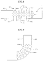
- FIG. 9 is a side view of the hinge depicted in FIGS. 5 to 8 in a deflected configuration.
- FIG. 10 is an end cross-sectional view of the distal shaft shown in FIG. 3 .
- FIG. 11 is a cross sectional view of a portion of the catheter tip section showing one means for attaching the puller wire.
- FIG. 12 is a top cross sectional views of a preferred puller wire anchor.
- FIG. 13 is a side cross sectional views of the puller wire anchor of FIG. 12 .
- the invention is directed to a deflectable device, such as a catheter, including a hinge that enhances the ability of the device to deflect or bend within a predetermined plane.
- the device can be deflected or bent upon application of a pulling force from within the device, such as by the use of a puller wire as is generally known in the art, or the device can be bent upon application of an outside force on a part of the device, such as by pushing a part of the device again tissue to cause the tissue to thereby exert a force onto a part of the device and bend that part of the device relative to the rest of the device.
- the term “deflectable” describes catheters having a straight configuration in the neutral position that can be deflected into a curved configuration, as well as catheters having a curved configuration in the neutral position that can be deflected into a straight configuration or into a different curved configuration.
- a steerable catheter having an irrigated electrode at its distal end.
- the catheter comprises an elongated catheter shaft 12 having proximal and distal ends, an intermediate shaft 14 at the distal end of the catheter shaft over which the hinge is mounted, a distal shaft 16 at the distal end of the intermediate shaft on which one or more electrodes or other devices are mounted for performing mapping, ablation or another desired function, and a control handle 18 at the proximal end of the catheter shaft.
- the catheter shaft 12 has a proximal region 20 and a distal region 22 having different degrees of flexibility. Such a design is particularly useful where it is desired to deflect the distal region 22 of the catheter shaft.
- the proximal region 20 is substantially longer than the distal region 22 , with the proximal region having an exemplary length ranging from about 90 cm to about 120 cm, and the distal region having an exemplary length ranging from about 1 cm to about 8 cm.
- the proximal region 20 of the catheter shaft 12 comprises an elongated tubular construction having a single, axial or central lumen 24 .
- the proximal region 20 is flexible, i.e., bendable, but substantially non-compressible along its length.
- the proximal region 20 can be of any suitable construction and made of any suitable material.
- a presently preferred construction comprises an outer wall 26 made of polyurethane or PEBAX.
- the outer wall 26 comprises an imbedded braided mesh of stainless steel or the like to increase torsional stiffness of the proximal region 20 so that, when the control handle 18 is rotated, the distal region 22 of the catheter shaft 12 will rotate in a corresponding manner.
- the inner surface of the outer wall 26 of the proximal region 20 is lined with a stiffening tube 28 , which can be made of any suitable material, preferably polyimide.
- the stiffening tube 28 along with the braided outer wall 26 , provides improved torsional stability while at the same time minimizing the wall thickness of the catheter, thus maximizing the diameter of the central lumen 24 .
- the outer diameter of the stiffening tube 28 is about the same as or slightly smaller than the inner diameter of the outer wall 26 .
- the outer diameter of the catheter shaft 12 is not critical, but is preferably no more than about 8 french, more preferably 7 french. Likewise the thickness of the outer wall 26 is not critical, but is thin enough so that the central lumen 24 can accommodate an infusion tube, a puller wire, lead wires, and any other wires, cables or tubes.
- the distal region 22 of the catheter shaft 12 comprises a short section of tubing having three lumens.
- the first lumen 30 a electrode carries lead wires
- the second lumen 32 a carries a puller wire
- the third lumen 34 a carries an infusion tube, as described in more detail below.
- the tubing of the distal region 22 is made of a suitable non-toxic material that is preferably more flexible than the proximal region 20 .
- a presently preferred material for the distal region 22 is braided polyurethane, i.e., polyurethane with an embedded mesh of braided stainless steel or the like.
- the number and sizes of the lumens are not critical and will depend on the components to be carried by the lumens.
- the proximal region 20 and distal region 22 have different degrees of flexibility to enhance deflection of the distal region of the catheter shaft.
- the catheter shaft can have a single stiffness along its length.
- the proximal and distal regions can be made, for example, of a single piece of tubing having only a single lumen extending therethrough.
- Other catheter shaft arrangements will be apparent to one skilled in the art and are within the scope of the invention.
- the intermediate shaft 14 which carries the hinge, and the distal shaft 16 , which carries one or more electrodes or other diagnostic or treatment devices.
- the intermediate shaft 14 comprises a flexible plastic tubing, preferably PEBAX.
- the distal shaft 16 similarly comprises a flexible plastic tubing, preferably PEBAX.
- the intermediate shaft 14 is more flexible than either of the distal region 22 of the catheter shaft 12 or the distal shaft 16 so as to not limit the ability of the intermediate shaft to bend, thereby allowing the hinge to control the extent and direction of bending of the intermediate shaft, as discussed further below.
- the plastic tubing that forms the intermediate shaft 14 preferably does not include a braided core within the plastic.
- the proximal region 20 comprises 72D durometer plastic
- the distal region 22 comprises 55D durometer plastic
- the intermediate shaft 14 comprises 35D durometer plastic
- the distal shaft 16 comprises 72D durometer plastic.
- the intermediate shaft 14 is connected to the distal end of the distal region 22 of the catheter shaft 12 and to the proximal end of the distal shaft 16 by any suitable method, for example, using thermal butt joints.
- the intermediate shaft 14 includes first, second and third lumens 30 b , 32 b , and 34 b that are aligned with the first, second and third lumens 30 a , 32 a , and 34 a , respectively, in the distal region 22 of the catheter shaft 12 .
- the distal shaft 16 includes first, second and third lumens 30 c , 32 c , and 34 c that are aligned with the first, second and third lumens 30 b , 32 b , and 34 b , respectively, of the intermediate shaft 14 .
- the number and arrangement of lumens in the intermediate shaft 14 can carry, but the lumens in the intermediate shaft are preferably aligned with the lumens in the distal region 22 of the catheter shaft 12 and in the distal shaft 16 , as discussed further below.
- a hinge 40 is mounted over the intermediate shaft 14 to control the direction and extent of bending of the intermediate shaft.
- the hinge 40 comprises a flexible tube, which can be made of any suitable material, such as Nitinol or plastic, having an outer wall 42 and an inner diameter that is slightly larger than the outer diameter of the intermediate shaft 14 so that the hinge can be mounted on the outside of the intermediate shaft, as shown in FIGS. 3 and 4 .
- the hinge 40 covers the entire intermediate shaft 14 to reduce the tendency of the intermediate shaft to kink when the hinge is bent.
- the hinge 40 includes one or more slots 44 extending through the outer wall 42 of the flexible tube, which affect the direction in which and extent to which the hinge can bend.
- the slots 44 of the hinge 40 are arranged to permit the hinge to bend in a single plane in a single direction and no more than approximately 90°.
- the outer wall 42 of the hinge 40 has a compressible side 46 and an expandable side 48 .
- the compressible side 46 is the side facing the direction toward which the hinge 40 bends, where the bending results in the compressible side of the hinge being compressed on itself.
- the expandable side 48 is the side opposite the compressible side 46 .
- the depicted hinge 40 includes a total of fourteen slots 44 divided evenly between the compressible side 46 and the expandable side 48 .
- each slot 44 is generally perpendicular to the axis of the hinge 40 , although the slots could alternatively be angled relative to the axis of the hinge so long as they are generally transverse to the axis of the hinge.
- the slots 44 on the compressible side 46 (“the compressible slots 44 a ”) are aligned with the slots 44 on the expandable side 48 (“the expandable slots 44 b ”), i.e., arranged so that corresponding slots on the compressible side and on the expandable side are positioned the same distance from an end of the hinge.
- the number, placement, size and shape of the slots 44 can vary depending on the desired effect to be achieved.
- the total number of slots on the hinge ranges from one to about thirty, more preferably from about ten to about twenty.
- the slots 44 can be provided only on the compressible side 46 , only on the expandable side 48 or divided in any desired manner between the two sides.
- the slots 44 are all the same depth Q, i.e., they all extend the same distance through the outer wall 42 of the hinge 40 towards the axis of the hinge.
- the depicted slots do not extend through the axis or center of the hinge 40 , so that the depth of each slot is less than the outer radius of the hinge.
- the slots can be deeper than the outer radius of the hinge so that they extend through the axis of the hinge 40 , although with such a design it is preferred that the compressible slots 44 a not be aligned with the expandible slots 44 b , but instead alternate in position.
- the compressible slots 44 a can have depths different from those of the expandible slots 44 b .
- the compressible slots 44 a of a single hinge can have varying depths and/or the expandible slots 44 b can have varying depths.
- each compressible slot 44 a comprises an elongated opening 50 having two ends of decreasing width and that terminate in circular openings 52 , which are preferably larger in diameter than the widest portion of the elongated opening.
- the compressible slots 44 a involve the removal of material from the flexible tube that forms the hinge.
- each elongated opening 50 decreases in width at an angle of 13°, varying from a maximum width of 0.011 inch to an end width (near the circular openings 52 ) of 0.006 inch, with the circular opening having a diameter of 0.020 inch, and with the distance D 1 between the compressible slots 44 a being approximately 0.021 inch.
- Each expandible slot 44 b comprises an elongated slot 54 of insignificant thickness, i.e., where no material is removed from the flexible tube, that terminates in a circular opening 56 like the circular openings 52 of the compressible slots 44 a .
- the circular openings 56 of the expandible slots 44 b have the same size as the circular openings 52 of the compressible slots 44 a , with the distance D 2 between the expandible slots 44 b being approximately 0.032 inch, so that the expandible slots 44 b are aligned with the compressible slots 44 a.
- the hinge In use, when a force is exerted on the distal shaft 16 , which is mounted on the distal end of the hinge 40 , the hinge is bent in a direction toward the compressible side 46 , as shown in FIG. 9 .
- the arrangement of the slots 44 forces the hinge to bend within the desired plane.
- the compressible slots 44 a are compressed so that the inwardly-angled openings 50 close, and the expandible slots 44 b expand so that the elongated slots 54 of insignificant thickness open, as best depicted in FIG. 9 .
- the inwardly-angled openings 50 are sized as described above such that they close and make further bending very difficult once the hinge 40 reaches a 90° angle.
- the depicted hinge 40 is designed to bend in a single plane in a single direction and no more than approximately 90°.
- the integrity of the hinge 40 is maintained by including a flexible hinge cover 60 over the hinge.
- the hinge cover 60 is preferably made of a biocompatible plastic, such as polyurethane, with a flexibility approximately equal to that of the intermediate shaft 14 .
- the hinge cover 60 like the intermediate shaft 14 , should not limit the ability of the hinge 40 to bend.
- the hinge cover 60 protects the hinge 40 against electrical conductivity, particularly when the hinge is made of Nitinol or another metal, and also protects against blood and other bodily fluids from entering and clogging the slots 44 of the hinge.
- the hinge cover 60 is longer than the hinge 40 and has proximal and distal ends extending beyond the hinge's proximal and distal ends, respectively.
- the hinge cover 60 can be secured in place over the hinge 40 by any suitable method, such as by gluing or thermally bonding the proximal end of the hinge cover 60 to the distal region 22 of the catheter shaft 12 and by gluing or thermally bonding the distal end of the hinge cover to the distal shaft 16 .
- the hinge 40 is described as being mounted over the intermediate shaft 14 , it could also be mounted within the intermediate shaft, for example, if the intermediate shaft has a single central lumen. Other arrangements for the hinge are also within the scope of the invention.
- the hinge can be formed by providing slots directly into a portion of the tubing that forms the catheter shaft
- the distal shaft 16 carries one or more electrodes for mapping and/or treatment or other treatment or diagnosis devices.
- the distal shaft 16 carries a porous electrode arrangement comprising a coil electrode 62 wrapped around a portion of the distal shaft over which is mounted a plastic sleeve 64 .
- the coil electrode 62 can be made of any electrically-conductive material, such as platinum or gold.
- the length of the coil electrode 62 can vary depending on the desired application, and preferably ranges from about 5 mm to about 20 mm, more preferably about 11 mm.
- the porous sleeve 64 can be made of any suitable biocompatible porous material through which fluid can pass, such as porous polytetrafluoroethylene.
- the porous sleeve 64 is sufficiently porous to permit saline to pass therethrough at a flowrate of at least 1 cc/min, more preferably from about 10 cc/min to about 60 cc/min, still more preferably from about 20 cc/min to about 40 cc/min.
- One or more irrigation openings 66 are provided in the wall of the distal shaft 16 that fluidly connect the third lumen 34 c of the distal shaft to the outside of the distal shaft.
- the distal shaft 16 includes three irrigation openings 66 , although this number can vary as desired.
- the irrigation openings 66 are provided between the coils of the coiled electrode 62 and underneath the porous sleeve 64 .
- the irrigation openings 66 permit fluid to pass from the third lumen 34 c of the distal shaft to the outside of the distal shaft within the porous sleeve 64 and then through the porous sleeve.
- the fluid is preferably saline or other conductive fluid so that current can pass from the coiled electrode 62 and through the fluid so that the fluid can be used to ablate tissue.
- the proximal and distal ends of the porous sleeve 64 can be attached to the distal shaft 16 by any suitable method that provides a fluid-tight seal to prevent fluid from leaking out the ends of the porous sleeve.
- a plastic thread (not shown), such as a Dacron® thread, is wrapped and cinched around the ends of the porous sleeve 64 and then sealed with polyurethane glue or the like.
- an infusion tube 68 is provided within the catheter shaft 12 .
- the infusion fluid 68 has a distal end mounted in the proximal end of the third lumen 34 a in the distal region 22 of the catheter shaft 12 , and a proximal end that extends outside the catheter through the control handle 18 , but could alternatively extend out through a sidearm, as is generally known in the art.
- a luer hub 69 is mounted on the proximal end of the infusion tube 68 so that fluid can be introduced into the infusion tube, through the third lumen 34 a in the distal region 22 of the catheter shaft 12 , through the third lumen 34 b of the intermediate shaft 14 , through the third lumen 34 c of the distal shaft 16 and out through the irrigation openings 66 .
- the distal end of the distal shaft 16 is sealed with polyurethane glue or the like to prevent fluid from passing out through the distal end of the third lumen 34 c , although other mechanisms for closing the distal end of the distal shaft can also be used.
- an electrode lead wire 70 is provided to electrically connect the coil electrode 62 to a source of radio frequency (RF) energy or other type of ablation energy.
- the electrode lead wire 70 extends through the central lumen 24 of the proximal region 20 of the catheter shaft 12 , through the first lumen 30 a of the distal region 22 of the catheter shaft, through the first lumen 30 b of the intermediate shaft 14 , through the first lumen 30 c of the distal shaft 16 , and out through a lead wire opening (not shown) in the distal shaft.
- the lead wire 70 Within the central lumen 24 of the catheter shaft 12 , the lead wire 70 extends through a protective tube 71 to prevent the lead wire from interfering with other components in the central lumen, although the protective tube can be eliminated if desired.
- the lead wire opening is potted with polyurethane glue or the like to prevent fluid from passing into the first lumen 30 c through the lead wire opening.
- the distal end of the lead wire 70 is then soldered, welded or otherwise electrically connected to the underside of the coil electrode 62 .
- the proximal end of the lead wire 70 extends through the control handle 18 and is connected to a suitable connector (not shown), which can be part of the control handle, that is connected to a source of ablation energy, as is generally known in the art.
- the distal shaft 16 also carries four ring electrodes 72 , although the presence and number of the ring electrodes can vary as desired.
- the ring electrodes 72 are particularly useful for mapping electrical activity within the heart and can be electrically connected to an appropriate monitoring apparatus (not shown) as is generally known in the art.
- Two ring electrodes 72 are mounted distal to the coil electrode 62 , and the other two are mounted proximal to the coil electrode, all within the porous sheath 64 .
- the ring electrodes 72 can be mounted over the proximal and distal ends of porous sheath 64 so long as they do not extend over the region over which the coil electrode 62 extends.
- Lead wires 70 electrically connect the ring electrodes 72 to a monitoring apparatus in a manner similar to the connection of a lead wire to the coil electrode or in any other manner known to those skilled in the art.
- thermocouples 74 can also be provided for monitoring the temperature of the tissue being ablated.
- two thermocouples 74 are provided, one just proximal to the coiled electrode 62 and one just distal to the coiled electrode.
- thermocouples could be provided in other locations, such as between the coils of the coiled electrode, or eliminated altogether.
- Each thermocouple comprises a pair of thermocouple wires 74 that extend, along with the lead wires 70 , through the central lumen 24 of the proximal region 20 of the catheter shaft 12 , through the first lumen 30 a of the distal region 22 of the catheter shaft, through the first lumen 30 b of the intermediate shaft 14 , through the first lumen 30 c of the distal shaft 16 and out through a thermocouple opening (not shown) in the distal shaft.
- the thermocouple openings are preferably potted with polyurethane glue or the like to hold the thermocouples 74 in place and to prevent fluid from passing into the first lumen 30 c of the distal shaft 16 .
- the distal shaft 16 can carry a variety of other electrode configurations.
- Other particularly useful electrode configurations for use with the inventive hinge design are described in U.S. Pat. No. 6,371,955, U.S. patent application Ser. No. 09/551,467, entitled “Catheter Having Mapping Assembly,” U.S. patent application Ser. No. 10/107,899, entitled “Bidirectional Catheter Having Mapping Assembly,” and U.S. patent application Ser. No. 10/118,680, entitled “Catheter Having Circular Ablation Assembly,” the entire disclosures of which are incorporated herein by reference.
- the distal shaft 16 could also carry other measurement and/or treatment devices, such as optic fibers, needles or balloons. The particular measurement or treatment device carried by the catheter is not critical to the invention.
- the catheter can also include a mechanism for deflecting the distal region 22 of the catheter shaft 12 .
- a puller wire 76 extends through proximal region 20 of the catheter shaft 12 , is anchored at its proximal end to the control handle 18 , and is anchored at its distal end to the distal region 22 of the catheter shaft.
- the puller wire 76 is made of any suitable metal, such as stainless steel or Nitinol, and is preferably coated with Teflon® or the like. The coating reduces the surface friction on the puller wire 76 during deflection.
- a compression coil 78 is situated within the proximal region 20 of the catheter shaft 12 in surrounding relation to the puller wire 76 .
- the compression coil 78 extends from the proximal end of the catheter shaft 12 to the proximal end of the distal region 22 of the catheter shaft.
- the compression coil 78 is made of any suitable metal, preferably stainless steel.
- the compression coil 78 is tightly wound on itself to provide flexibility, i.e., bending, but to resist compression.
- the inner diameter of the compression coil 78 is preferably slightly larger than the diameter of the puller wire 76 .
- the Teflon® coating on the puller wire 76 allows it to slide freely within the compression coil 78 .
- the outer surface of the compression coil 78 is covered by a flexible, non-conductive sheath 80 , e.g., made of polyimide tubing, to prevent contact between the compression coil and the lead wires and/or thermocouple wires within the catheter shaft 12 .
- a flexible, non-conductive sheath 80 e.g., made of polyimide tubing
- the compression coil 78 is anchored at its proximal end to the outer wall 26 of the catheter shaft 12 by proximal glue joint 82 and at its distal end to the distal region 22 by distal glue joint 84 .
- Both glue joints 82 and 84 preferably comprise polyurethane glue or the like.
- the glue may be applied by means of a syringe or the like through a hole made between the outer surface of the catheter shaft 12 and the central lumen 24 .
- the puller wire 76 extends into the second lumen 32 a of the distal region 22 of the catheter shaft 12 .
- the puller wire 76 is anchored at its distal end to the side of the distal region 22 , as shown in FIGS. 11 to 13 .
- a T-shaped anchor 86 is formed which comprises a short piece of tubular stainless steel 88 , e.g., hypodermic stock, which is fitted over the distal end of the puller wire 76 and crimped to fixedly secure it to the puller wire.
- the distal end of the tubular stainless steel 88 is fixedly attached, e.g., by welding, to a stainless steel cross-piece 90 , such as stainless steel ribbon or the like.
- the cross-piece 90 sits in a notch 92 in a wall of the distal region 22 that extends into the second lumen 32 a .
- the stainless steel cross-piece 90 is larger than the notch 92 and, therefore, cannot be pulled through the notch.
- the portion of the notch 92 not filled by the cross-piece 90 is filled with glue or the like, preferably a polyurethane glue, which is harder than the material of the distal region 22 . Rough edges, if any, of the cross-piece 90 are polished to provide a smooth, continuous surface with the outer surface of the distal region 22 .
- the puller wire 76 extends through a plastic, preferably Teflon®, puller wire sheath 94 , which prevents the puller wire 76 from cutting into the wall of the distal region 22 when the distal region is deflected.
- a plastic preferably Teflon®
- puller wire sheath 94 Any other suitable technique for anchoring the puller wire 76 in the distal region 22 can also be used.
- other means for deflecting the distal region can be provided, such as the deflection mechanism described in U.S. Pat. No. 5,537,686, the disclosure of which is incorporated herein by reference.
- control handle 18 Longitudinal movement of the puller wire 76 relative to the proximal region 20 of the catheter shaft 12 , which results in deflection of the distal region 22 , is accomplished by suitable manipulation of the control handle 18 .
- suitable control handles for use in the present invention are disclosed, for example, in U.S. Pat. No. Re 34,502 and U.S. Pat. No. 5,897,529, the entire disclosures of which are incorporated herein by reference.
- the precise structure of the control handle is not critical so long as it is capable of manipulating the puller wire or other means for deflecting the distal region.
- two or more puller wires can be provided to enhance the ability to manipulate the tip section.
- a second puller wire and a surrounding second compression coil extend through the catheter body and into an additional off-axis lumen in the tip section.
- the first puller wire is preferably anchored proximal to the anchor location of the second puller wire.
- the puller wire 76 terminates in the catheter shaft 12 , the second lumens 32 b and 32 c of the intermediate shaft 14 and the distal shaft 16 are empty.
- the puller wire 76 could instead be anchored in the distal shaft 16 in manner essentially identical to that described above with respect to the distal region 22 of the catheter shaft 12 so as to permit the use to actively deflect the distal shaft.
- separate puller wires could be provided for deflection of the distal region 22 of the catheter shaft 12 and for deflection of the distal shaft 16 .
- a suitable guiding sheath is inserted into the patient.
- An example of a suitable guiding sheath for use in connection with the present invention is the PrefaceTM Braided Guiding Sheath, commercially available from Biosense Webster (Diamond Bar, Calif.).
- the distal end of the sheath is guided into one of the atria or other region of the heart.
- a catheter according to the present invention is fed through the guiding sheath until its distal end extends out of the distal end of the guiding sheath.
- the distal shaft is positioned for the desired mapping or treatment procedure. If the distal shaft carries a porous electrode, the porous electrode can then be used to form continuous linear lesions by ablation. If the distal shaft carries other electrode arrangements, the electrodes can be used for ablating or mapping, as desired. If the distal shaft carries some other component, such as a balloon or optic fiber, that other component can be used for diagnosis and/or treatment as is generally known in the art. The positioning of the distal shaft can be performed by simply pushing the distal shaft against the heart tissue to thereby cause the distal shaft to deflect or bend toward the catheter shaft.
- the presence of the hinge will enhance the ability of the distal shaft to bend in a single plane in the desired direction and can also limit the extent to which the distal shaft bends.
- a puller wire or other deflection mechanism is provided within the distal shaft, the user can actively deflect or bend the distal shaft, with the hinge again serving to enhance the ability of the distal shaft to bend in a single plane in the desired direction and optionally limit the extent to which the distal shaft bends.
Abstract
Description
Claims (25)
Priority Applications (8)
| Application Number | Priority Date | Filing Date | Title |
|---|---|---|---|
| US10/386,868 US7276062B2 (en) | 2003-03-12 | 2003-03-12 | Deflectable catheter with hinge |
| EP04251137A EP1457224B1 (en) | 2003-03-12 | 2004-02-27 | Deflectable catheter with hinge |
| DE602004015353T DE602004015353D1 (en) | 2003-03-12 | 2004-02-27 | Flexible catheter with joint |
| JP2004069301A JP4583783B2 (en) | 2003-03-12 | 2004-03-11 | Hinged deflectable catheter |
| US11/866,352 US8764743B2 (en) | 2003-03-12 | 2007-10-02 | Deflectable catheter with hinge |
| US14/320,124 US9636482B2 (en) | 2003-03-12 | 2014-06-30 | Deflectable catheter with hinge |
| US15/582,394 US10183150B2 (en) | 2003-03-12 | 2017-04-28 | Deflectable catheter with hinge |
| US16/252,528 US10814100B2 (en) | 2003-03-12 | 2019-01-18 | Deflectable catheter with hinge |
Applications Claiming Priority (1)
| Application Number | Priority Date | Filing Date | Title |
|---|---|---|---|
| US10/386,868 US7276062B2 (en) | 2003-03-12 | 2003-03-12 | Deflectable catheter with hinge |
Related Child Applications (1)
| Application Number | Title | Priority Date | Filing Date |
|---|---|---|---|
| US11/866,352 Continuation US8764743B2 (en) | 2003-03-12 | 2007-10-02 | Deflectable catheter with hinge |
Publications (2)
| Publication Number | Publication Date |
|---|---|
| US20040181136A1 US20040181136A1 (en) | 2004-09-16 |
| US7276062B2 true US7276062B2 (en) | 2007-10-02 |
Family
ID=32771600
Family Applications (5)
| Application Number | Title | Priority Date | Filing Date |
|---|---|---|---|
| US10/386,868 Expired - Lifetime US7276062B2 (en) | 2003-03-12 | 2003-03-12 | Deflectable catheter with hinge |
| US11/866,352 Active 2024-09-09 US8764743B2 (en) | 2003-03-12 | 2007-10-02 | Deflectable catheter with hinge |
| US14/320,124 Expired - Lifetime US9636482B2 (en) | 2003-03-12 | 2014-06-30 | Deflectable catheter with hinge |
| US15/582,394 Expired - Lifetime US10183150B2 (en) | 2003-03-12 | 2017-04-28 | Deflectable catheter with hinge |
| US16/252,528 Expired - Lifetime US10814100B2 (en) | 2003-03-12 | 2019-01-18 | Deflectable catheter with hinge |
Family Applications After (4)
| Application Number | Title | Priority Date | Filing Date |
|---|---|---|---|
| US11/866,352 Active 2024-09-09 US8764743B2 (en) | 2003-03-12 | 2007-10-02 | Deflectable catheter with hinge |
| US14/320,124 Expired - Lifetime US9636482B2 (en) | 2003-03-12 | 2014-06-30 | Deflectable catheter with hinge |
| US15/582,394 Expired - Lifetime US10183150B2 (en) | 2003-03-12 | 2017-04-28 | Deflectable catheter with hinge |
| US16/252,528 Expired - Lifetime US10814100B2 (en) | 2003-03-12 | 2019-01-18 | Deflectable catheter with hinge |
Country Status (4)
| Country | Link |
|---|---|
| US (5) | US7276062B2 (en) |
| EP (1) | EP1457224B1 (en) |
| JP (1) | JP4583783B2 (en) |
| DE (1) | DE602004015353D1 (en) |
Cited By (80)
| Publication number | Priority date | Publication date | Assignee | Title |
|---|---|---|---|---|
| US20080154272A1 (en) * | 2005-08-16 | 2008-06-26 | Laurent Schaller | Apparatus and Method for Treating Bone |
| US20090240699A1 (en) * | 2008-03-18 | 2009-09-24 | Morgan Christopher B | Integration for intelligence data systems |
| US20090287187A1 (en) * | 2008-05-07 | 2009-11-19 | Guided Delivery Systems Inc. | Deflectable guide |
| US20090299352A1 (en) * | 2007-12-21 | 2009-12-03 | Boston Scientific Scimed, Inc. | Steerable laser-energy delivery device |
| US20090326450A1 (en) * | 2008-06-27 | 2009-12-31 | Boston Scientific Scimed, Inc. | Steerable medical device |
| US20100069882A1 (en) * | 2008-09-18 | 2010-03-18 | Boston Scientific Scimed, Inc. | Medical device with preferential bending |
| US8323241B2 (en) | 2009-06-24 | 2012-12-04 | Shifamed Holdings, Llc | Steerable medical delivery devices and methods of use |
| US8454617B2 (en) | 2005-08-16 | 2013-06-04 | Benvenue Medical, Inc. | Devices for treating the spine |
| US8591583B2 (en) | 2005-08-16 | 2013-11-26 | Benvenue Medical, Inc. | Devices for treating the spine |
| US8708953B2 (en) | 2009-06-24 | 2014-04-29 | Shifamed Holdings, Llc | Steerable medical delivery devices and methods of use |
| US8801787B2 (en) | 2005-08-16 | 2014-08-12 | Benvenue Medical, Inc. | Methods of distracting tissue layers of the human spine |
| US8814873B2 (en) | 2011-06-24 | 2014-08-26 | Benvenue Medical, Inc. | Devices and methods for treating bone tissue |
| US8888773B2 (en) | 2012-05-11 | 2014-11-18 | Medtronic Ardian Luxembourg S.A.R.L. | Multi-electrode catheter assemblies for renal neuromodulation and associated systems and methods |
| US20150005761A1 (en) * | 2012-08-10 | 2015-01-01 | William J. Zinnanti | Electrosurgery probes with smoke and liquid evacuation |
| US8951288B2 (en) | 2010-11-09 | 2015-02-10 | Benvenue Medical, Inc. | Devices and methods for treatment of a bone fracture |
| US8956352B2 (en) | 2010-10-25 | 2015-02-17 | Medtronic Ardian Luxembourg S.A.R.L. | Catheter apparatuses having multi-electrode arrays for renal neuromodulation and associated systems and methods |
| US8961550B2 (en) | 2012-04-17 | 2015-02-24 | Indian Wells Medical, Inc. | Steerable endoluminal punch |
| US8992470B2 (en) | 2006-05-19 | 2015-03-31 | Boston Scientific Scimed, Inc. | Control mechanism for steerable medical device |
| US9044575B2 (en) | 2012-10-22 | 2015-06-02 | Medtronic Adrian Luxembourg S.a.r.l. | Catheters with enhanced flexibility and associated devices, systems, and methods |
| US9084610B2 (en) | 2010-10-21 | 2015-07-21 | Medtronic Ardian Luxembourg S.A.R.L. | Catheter apparatuses, systems, and methods for renal neuromodulation |
| US9173646B2 (en) | 2009-01-20 | 2015-11-03 | Guided Delivery Systems Inc. | Diagnostic catheters, guide catheters, visualization devices and chord manipulation devices, and related kits and methods |
| US9399115B2 (en) | 2012-10-22 | 2016-07-26 | Medtronic Ardian Luxembourg S.A.R.L. | Catheters with enhanced flexibility and associated devices, systems, and methods |
| US20160361088A1 (en) * | 2015-06-12 | 2016-12-15 | Covidien Lp | Catheter with pre-formed geometry for body lumen access |
| US20170086652A1 (en) * | 2015-01-21 | 2017-03-30 | Olympus Corporation | Endoscope insertion portion and endoscope |
| US20170095138A1 (en) * | 2014-10-01 | 2017-04-06 | Olympus Corporation | Endoscope bending tube and endoscope provided with endoscope bending tube |
| US9649158B2 (en) | 2012-03-02 | 2017-05-16 | Biosense Webster (Israel) Ltd. | Catheter for treatment of atrial flutter having single action dual deflection mechanism |
| CN106999238A (en) * | 2014-09-17 | 2017-08-01 | 威廉·J·辛南迪 | Smoke evacuation and discharge opeing formula electrosurgery probe |
| US9788963B2 (en) | 2003-02-14 | 2017-10-17 | DePuy Synthes Products, Inc. | In-situ formed intervertebral fusion device and method |
| US9855404B2 (en) | 2013-05-03 | 2018-01-02 | St. Jude Medical International Holding S.À R.L. | Dual bend radii steering catheter |
| WO2018017349A1 (en) * | 2016-07-18 | 2018-01-25 | Scientia Vascular, Llc | Guidewire devices having shapeable tips and bypass cuts |
| US9918705B2 (en) | 2016-07-07 | 2018-03-20 | Brian Giles | Medical devices with distal control |
| US9950137B2 (en) | 2009-04-03 | 2018-04-24 | Scientia Vascular, Llc | Micro-fabricated guidewire devices formed with hybrid materials |
| US10085783B2 (en) | 2013-03-14 | 2018-10-02 | Izi Medical Products, Llc | Devices and methods for treating bone tissue |
| US10166069B2 (en) | 2014-01-27 | 2019-01-01 | Medtronic Ardian Luxembourg S.A.R.L. | Neuromodulation catheters having jacketed neuromodulation elements and related devices, systems, and methods |
| US10232141B2 (en) | 2008-12-08 | 2019-03-19 | Scientia Vascular, Llc | Micro-cutting systems for forming cuts in products |
| US10327933B2 (en) * | 2015-04-28 | 2019-06-25 | Cook Medical Technologies Llc | Medical cannulae, delivery systems and methods |
| US10363389B2 (en) | 2009-04-03 | 2019-07-30 | Scientia Vascular, Llc | Micro-fabricated guidewire devices having varying diameters |
| WO2019156940A1 (en) | 2018-02-06 | 2019-08-15 | Biosense Webster (Israel) Ltd. | Catheter with increased electrode density spine assembly having reinforced spine covers |
| WO2019156945A1 (en) | 2018-02-06 | 2019-08-15 | Biosense Webster (Israel) Ltd. | Catheter with staggered electrodes spine assembly |
| WO2019155356A1 (en) | 2018-02-06 | 2019-08-15 | Biosense Webster (Israel) Ltd. | Catheter with electrode spine assembly having preformed configurations for improved tissue contact |
| WO2019156942A1 (en) | 2018-02-06 | 2019-08-15 | Biosense Webster (Israel) Ltd. | Medical probe with staggered microelectrode configuration |
| US10391274B2 (en) | 2016-07-07 | 2019-08-27 | Brian Giles | Medical device with distal torque control |
| US10420537B2 (en) | 2015-03-27 | 2019-09-24 | Shifamed Holdings, Llc | Steerable medical devices, systems, and methods of use |
| US10433905B2 (en) | 2013-03-15 | 2019-10-08 | Medtronic Ardian Luxembourg S.A.R.L. | Multi-electrode apposition judgment using pressure elements |
| US10548663B2 (en) | 2013-05-18 | 2020-02-04 | Medtronic Ardian Luxembourg S.A.R.L. | Neuromodulation catheters with shafts for enhanced flexibility and control and associated devices, systems, and methods |
| US20200205796A1 (en) * | 2018-12-28 | 2020-07-02 | DePuy Synthes Products, Inc. | Steerable locking catheter |
| US10736690B2 (en) | 2014-04-24 | 2020-08-11 | Medtronic Ardian Luxembourg S.A.R.L. | Neuromodulation catheters and associated systems and methods |
| US10821268B2 (en) | 2016-09-14 | 2020-11-03 | Scientia Vascular, Llc | Integrated coil vascular devices |
| US10888433B2 (en) | 2016-12-14 | 2021-01-12 | DePuy Synthes Products, Inc. | Intervertebral implant inserter and related methods |
| US10933221B2 (en) | 2015-11-09 | 2021-03-02 | Kalila Medical, Inc. | Steering assemblies for medical devices, and methods of use |
| US10940016B2 (en) | 2017-07-05 | 2021-03-09 | Medos International Sarl | Expandable intervertebral fusion cage |
| US10966840B2 (en) | 2010-06-24 | 2021-04-06 | DePuy Synthes Products, Inc. | Enhanced cage insertion assembly |
| US10973652B2 (en) | 2007-06-26 | 2021-04-13 | DePuy Synthes Products, Inc. | Highly lordosed fusion cage |
| US10980529B2 (en) | 2015-03-05 | 2021-04-20 | Ancora Heart, Inc. | Devices and methods of visualizing and determining depth of penetration in cardiac tissue |
| US11052228B2 (en) | 2016-07-18 | 2021-07-06 | Scientia Vascular, Llc | Guidewire devices having shapeable tips and bypass cuts |
| US11052226B2 (en) | 2015-04-24 | 2021-07-06 | Kalila Medical, Inc. | Steerable medical devices, systems, and methods of use |
| US20210251757A1 (en) * | 2018-11-20 | 2021-08-19 | Edwards Lifesciences Corporation | Deployment tools and methods for delivering a device to a native heart valve |
| US11273050B2 (en) | 2006-12-07 | 2022-03-15 | DePuy Synthes Products, Inc. | Intervertebral implant |
| US11305095B2 (en) | 2018-02-22 | 2022-04-19 | Scientia Vascular, Llc | Microfabricated catheter having an intermediate preferred bending section |
| US11344424B2 (en) | 2017-06-14 | 2022-05-31 | Medos International Sarl | Expandable intervertebral implant and related methods |
| US11369351B2 (en) | 2017-05-26 | 2022-06-28 | Scientia Vascular, Inc. | Micro-fabricated medical device having a non-helical cut arrangement |
| US11406791B2 (en) | 2009-04-03 | 2022-08-09 | Scientia Vascular, Inc. | Micro-fabricated guidewire devices having varying diameters |
| US11426286B2 (en) | 2020-03-06 | 2022-08-30 | Eit Emerging Implant Technologies Gmbh | Expandable intervertebral implant |
| US11426290B2 (en) | 2015-03-06 | 2022-08-30 | DePuy Synthes Products, Inc. | Expandable intervertebral implant, system, kit and method |
| US11446156B2 (en) | 2018-10-25 | 2022-09-20 | Medos International Sarl | Expandable intervertebral implant, inserter instrument, and related methods |
| US11446155B2 (en) | 2017-05-08 | 2022-09-20 | Medos International Sarl | Expandable cage |
| US11452541B2 (en) | 2016-12-22 | 2022-09-27 | Scientia Vascular, Inc. | Intravascular device having a selectively deflectable tip |
| US11452607B2 (en) | 2010-10-11 | 2022-09-27 | DePuy Synthes Products, Inc. | Expandable interspinous process spacer implant |
| US11497619B2 (en) | 2013-03-07 | 2022-11-15 | DePuy Synthes Products, Inc. | Intervertebral implant |
| US11510788B2 (en) | 2016-06-28 | 2022-11-29 | Eit Emerging Implant Technologies Gmbh | Expandable, angularly adjustable intervertebral cages |
| US11596522B2 (en) | 2016-06-28 | 2023-03-07 | Eit Emerging Implant Technologies Gmbh | Expandable and angularly adjustable intervertebral cages with articulating joint |
| US11602438B2 (en) | 2008-04-05 | 2023-03-14 | DePuy Synthes Products, Inc. | Expandable intervertebral implant |
| US11607321B2 (en) | 2009-12-10 | 2023-03-21 | DePuy Synthes Products, Inc. | Bellows-like expandable interbody fusion cage |
| US11612491B2 (en) | 2009-03-30 | 2023-03-28 | DePuy Synthes Products, Inc. | Zero profile spinal fusion cage |
| US11654033B2 (en) | 2010-06-29 | 2023-05-23 | DePuy Synthes Products, Inc. | Distractible intervertebral implant |
| US11737881B2 (en) | 2008-01-17 | 2023-08-29 | DePuy Synthes Products, Inc. | Expandable intervertebral implant and associated method of manufacturing the same |
| US11752009B2 (en) | 2021-04-06 | 2023-09-12 | Medos International Sarl | Expandable intervertebral fusion cage |
| US11813418B2 (en) | 2019-08-22 | 2023-11-14 | Becton, Dickinson And Company | Echogenic balloon dilation catheter and balloon thereof |
| US11850160B2 (en) | 2021-03-26 | 2023-12-26 | Medos International Sarl | Expandable lordotic intervertebral fusion cage |
| US11911287B2 (en) | 2010-06-24 | 2024-02-27 | DePuy Synthes Products, Inc. | Lateral spondylolisthesis reduction cage |
Families Citing this family (63)
| Publication number | Priority date | Publication date | Assignee | Title |
|---|---|---|---|---|
| US7276062B2 (en) * | 2003-03-12 | 2007-10-02 | Biosence Webster, Inc. | Deflectable catheter with hinge |
| US20080319418A1 (en) * | 2004-03-30 | 2008-12-25 | Cathrx Pty Ltd | Catheter Steering Device |
| DE102004051211A1 (en) | 2004-10-20 | 2006-05-04 | Restate Treuhand & Immobilien Ag | Catheter, in particular for introducing pacemaker or ICD electrodes into a patient's body |
| US7623899B2 (en) * | 2005-09-16 | 2009-11-24 | Biosense Webster, Inc. | Catheter with flexible pre-shaped tip section |
| US8292827B2 (en) * | 2005-12-12 | 2012-10-23 | Boston Scientific Scimed, Inc. | Micromachined medical devices |
| US20070208405A1 (en) * | 2006-03-06 | 2007-09-06 | Boston Scientific Scimed, Inc. | Stent delivery catheter |
| US20070213669A1 (en) * | 2006-03-07 | 2007-09-13 | Boston Scientific Scimed, Inc. | Flexible sleeve, adjustable contact surface, and fluid contact monitor for catheter |
| US7774039B2 (en) | 2006-09-05 | 2010-08-10 | Boston Scientific Scimed, Inc. | Multi-bend steerable mapping catheter |
| US20080097347A1 (en) * | 2006-09-22 | 2008-04-24 | Babak Arvanaghi | Bendable needle assembly |
| EP2094352A4 (en) | 2006-12-06 | 2010-05-19 | Cleveland Clinic Foundation | Method and system for treating acute heart failure by neuromodulation |
| US8821477B2 (en) | 2007-08-06 | 2014-09-02 | Boston Scientific Scimed, Inc. | Alternative micromachined structures |
| US8066703B2 (en) * | 2007-10-08 | 2011-11-29 | Boston Scientific Scimed, Inc. | Sphincterotome with improved orientation |
| US8460213B2 (en) | 2008-01-03 | 2013-06-11 | Boston Scientific Scimed, Inc. | Cut tubular members for a medical device and methods for making and using the same |
| WO2010096347A1 (en) | 2009-02-20 | 2010-08-26 | Boston Scientific Scimed, Inc. | Asymmetric dual directional steerable catheter sheath |
| US20110270238A1 (en) * | 2009-12-31 | 2011-11-03 | Raed Rizq | Compliant Cryoballoon Apparatus for Denervating Ostia of the Renal Arteries |
| US10765473B2 (en) | 2010-11-08 | 2020-09-08 | Baylis Medical Company Inc. | Electrosurgical device having a lumen |
| WO2014141105A1 (en) * | 2013-03-12 | 2014-09-18 | Baylis Medical Company Inc. | Medical device having a support structure |
| AU2012212492B2 (en) | 2011-02-01 | 2016-05-12 | Channel Medsystems, Inc. | Methods and apparatus for cryogenic treatment of a body cavity or lumen |
| AU2012221758B2 (en) | 2011-02-24 | 2017-05-04 | Eximo Medical Ltd. | Hybrid catheter for tissue resection |
| US9717554B2 (en) | 2012-03-26 | 2017-08-01 | Biosense Webster (Israel) Ltd. | Catheter with composite construction |
| US10639099B2 (en) * | 2012-05-25 | 2020-05-05 | Biosense Webster (Israel), Ltd. | Catheter having a distal section with spring sections for biased deflection |
| US9243726B2 (en) | 2012-10-03 | 2016-01-26 | Aarne H. Reid | Vacuum insulated structure with end fitting and method of making same |
| US9549666B2 (en) | 2012-11-10 | 2017-01-24 | Curvo Medical, Inc. | Coaxial micro-endoscope |
| US9233225B2 (en) | 2012-11-10 | 2016-01-12 | Curvo Medical, Inc. | Coaxial bi-directional catheter |
| US10149720B2 (en) * | 2013-03-08 | 2018-12-11 | Auris Health, Inc. | Method, apparatus, and a system for facilitating bending of an instrument in a surgical or medical robotic environment |
| US11937873B2 (en) | 2013-03-12 | 2024-03-26 | Boston Scientific Medical Device Limited | Electrosurgical device having a lumen |
| AU2014262639B2 (en) * | 2013-05-08 | 2016-12-22 | Boston Scientific Scimed, Inc. | Systems and methods for temperature monitoring and control during an ablation procedure |
| US20140361529A1 (en) * | 2013-06-06 | 2014-12-11 | Daniel George McCormick | Pipeline expansion loop protector |
| US9839765B2 (en) | 2013-11-12 | 2017-12-12 | St. Jude Medical, Cardiology Division, Inc. | Transfemoral mitral valve repair delivery device |
| US10610279B2 (en) | 2014-04-10 | 2020-04-07 | Channel Medsystems, Inc. | Apparatus and methods for regulating cryogenic treatment |
| EP3552571A3 (en) | 2014-05-18 | 2019-11-27 | Eximo Medical Ltd. | System for tissue ablation using pulsed laser |
| JP6580068B2 (en) | 2014-05-22 | 2019-09-25 | カーディオノミック,インク. | Catheter and catheter system for electrical neuromodulation |
| AU2015315658B2 (en) | 2014-09-08 | 2019-05-23 | CARDIONOMIC, Inc. | Catheter and electrode systems for electrical neuromodulation |
| EP3194017A1 (en) | 2014-09-08 | 2017-07-26 | Cardionomic, Inc. | Methods for electrical neuromodulation of the heart |
| SG11201705394TA (en) | 2015-01-05 | 2017-07-28 | Cardionomic Inc | Cardiac modulation facilitation methods and systems |
| US10675057B2 (en) | 2015-04-28 | 2020-06-09 | Cook Medical Technologies Llc | Variable stiffness cannulae and associated delivery systems and methods |
| US20160346513A1 (en) * | 2015-05-26 | 2016-12-01 | Vanderbilt University | Surgical device tip with arc length varying curvature |
| US10154905B2 (en) | 2015-08-07 | 2018-12-18 | Medtronic Vascular, Inc. | System and method for deflecting a delivery catheter |
| US10497908B2 (en) | 2015-08-24 | 2019-12-03 | Concept Group, Llc | Sealed packages for electronic and energy storage devices |
| AU2017229496B2 (en) | 2016-03-09 | 2022-03-31 | CARDIONOMIC, Inc. | Cardiac contractility neurostimulation systems and methods |
| CN109414292A (en) | 2016-05-05 | 2019-03-01 | 爱克斯莫医疗有限公司 | Device and method for cutting off and/or melting unwanted tissue |
| US10555756B2 (en) | 2016-06-27 | 2020-02-11 | Cook Medical Technologies Llc | Medical devices having coaxial cannulae |
| US10716916B2 (en) | 2016-07-21 | 2020-07-21 | Creganna Unlimited Company | High load steerable shaft and method for cardiac catheter |
| US10493240B2 (en) * | 2016-07-28 | 2019-12-03 | Cook Medical Technologies Llc | Steerable catheter handle |
| AU2017301399B2 (en) * | 2016-07-28 | 2019-05-16 | Cook Medical Technologies Llc | Distal wire securement in steerable catheter |
| CA3043868A1 (en) | 2016-11-15 | 2018-05-24 | Concept Group Llc | Multiply-insulated assemblies |
| JP7202766B2 (en) | 2016-11-15 | 2023-01-12 | コンセプト グループ エルエルシー | Vacuum insulation article reinforced with microporous insulation |
| US11534078B2 (en) | 2016-12-07 | 2022-12-27 | Biosense Webster (Israel) Ltd. | Steerable guiding sheath with ring electrodes and related method of construction |
| US10589060B2 (en) | 2016-12-21 | 2020-03-17 | Biosense Webster (Israel) Ltd. | Extrusion with preferential bend axis |
| WO2018163899A1 (en) * | 2017-03-06 | 2018-09-13 | テルモ株式会社 | Puncture device, medical device, and treatment method |
| JP6937151B2 (en) * | 2017-03-31 | 2021-09-22 | 川澄化学工業株式会社 | Medical tubular members, foreign body removal devices and foreign body removal catheters |
| CN111465800B (en) | 2017-08-25 | 2022-03-01 | 概念集团有限责任公司 | Multi-geometry and multi-material thermal insulation component |
| EP3664703A4 (en) | 2017-09-13 | 2021-05-12 | Cardionomic, Inc. | Neurostimulation systems and methods for affecting cardiac contractility |
| US10456556B2 (en) * | 2018-02-19 | 2019-10-29 | Bendit Technologies Ltd. | Steering tool with enhanced flexibility and trackability |
| CA3107959A1 (en) | 2018-08-13 | 2020-02-20 | CARDIONOMIC, Inc. | Systems and methods for affecting cardiac contractility and/or relaxation |
| US11583168B2 (en) * | 2018-11-08 | 2023-02-21 | Thomas J. Viren | Endotracheal tube system and method |
| CN109567991B (en) * | 2018-12-05 | 2021-02-19 | 东莞市先健医疗有限公司 | Conveying sheath |
| WO2020176774A1 (en) * | 2019-02-27 | 2020-09-03 | Concept Group Llc | Vacuum-insulated medical devices |
| CN114040704A (en) | 2019-05-06 | 2022-02-11 | 卡迪诺米克公司 | System and method for denoising physiological signals during electrical neuromodulation |
| WO2021045132A1 (en) * | 2019-09-04 | 2021-03-11 | タツタ電線株式会社 | Movable shaft and medical equipment having movable shaft |
| US11471650B2 (en) | 2019-09-20 | 2022-10-18 | Biosense Webster (Israel) Ltd. | Mechanism for manipulating a puller wire |
| WO2021183614A1 (en) * | 2020-03-11 | 2021-09-16 | Stryker Corporation | Slotted medical devices with fillers |
| US11872357B2 (en) | 2020-11-09 | 2024-01-16 | Agile Devices, Inc. | Devices for steering catheters |
Citations (20)
| Publication number | Priority date | Publication date | Assignee | Title |
|---|---|---|---|---|
| US3109461A (en) | 1960-12-06 | 1963-11-05 | Gen Electric | Hose structure |
| US4353358A (en) | 1980-08-28 | 1982-10-12 | Emerson Reynolds L | Sigmoidoscope |
| US4911148A (en) | 1989-03-14 | 1990-03-27 | Intramed Laboratories, Inc. | Deflectable-end endoscope with detachable flexible shaft assembly |
| US5304131A (en) | 1991-07-15 | 1994-04-19 | Paskar Larry D | Catheter |
| US5381782A (en) * | 1992-01-09 | 1995-01-17 | Spectrum Medsystems Corporation | Bi-directional and multi-directional miniscopes |
| US5437288A (en) | 1992-09-04 | 1995-08-01 | Mayo Foundation For Medical Education And Research | Flexible catheter guidewire |
| US5467763A (en) | 1992-01-21 | 1995-11-21 | Mcmahon; Michael J. | Surgical instruments |
| EP0937481A1 (en) | 1998-02-19 | 1999-08-25 | Precision Vascular Systems, Inc. | Catheter or guidewire with varying flexibility |
| US5961513A (en) * | 1996-01-19 | 1999-10-05 | Ep Technologies, Inc. | Tissue heating and ablation systems and methods using porous electrode structures |
| US5971975A (en) * | 1996-10-09 | 1999-10-26 | Target Therapeutics, Inc. | Guide catheter with enhanced guidewire tracking |
| US6012494A (en) * | 1995-03-16 | 2000-01-11 | Deutsche Forschungsanstalt Fur Luft- Und Raumfahrt E.V. | Flexible structure |
| US6027863A (en) | 1991-09-05 | 2000-02-22 | Intratherapeutics, Inc. | Method for manufacturing a tubular medical device |
| US6102886A (en) * | 1992-08-12 | 2000-08-15 | Vidamed, Inc. | Steerable medical probe with stylets |
| US6210409B1 (en) * | 1999-05-03 | 2001-04-03 | Alan G. Ellman | Electrosurgical handpiece for treating tissue |
| US6338725B1 (en) | 1994-10-24 | 2002-01-15 | Medtronic Ave, Inc. | Large-diameter introducer sheath having hemostasis valve and removable steering mechanism |
| US20030009208A1 (en) | 2001-07-05 | 2003-01-09 | Precision Vascular Systems, Inc. | Torqueable soft tip medical device and method of usage |
| US6585718B2 (en) * | 2001-05-02 | 2003-07-01 | Cardiac Pacemakers, Inc. | Steerable catheter with shaft support system for resisting axial compressive loads |
| US6591472B1 (en) * | 1998-12-08 | 2003-07-15 | Medtronic, Inc. | Multiple segment catheter and method of fabrication |
| US6647281B2 (en) * | 2001-04-06 | 2003-11-11 | Scimed Life Systems, Inc. | Expandable diagnostic or therapeutic apparatus and system for introducing the same into the body |
| US6699241B2 (en) * | 2000-08-11 | 2004-03-02 | Northeastern University | Wide-aperture catheter-based microwave cardiac ablation antenna |
Family Cites Families (36)
| Publication number | Priority date | Publication date | Assignee | Title |
|---|---|---|---|---|
| US9208A (en) * | 1852-08-17 | Improvement in processes for making paints | ||
| US4742817A (en) * | 1985-05-15 | 1988-05-10 | Olympus Optical Co., Ltd. | Endoscopic apparatus having a bendable insertion section |
| US4960134A (en) * | 1988-11-18 | 1990-10-02 | Webster Wilton W Jr | Steerable catheter |
| US5891088A (en) * | 1990-02-02 | 1999-04-06 | Ep Technologies, Inc. | Catheter steering assembly providing asymmetric left and right curve configurations |
| US5273535A (en) * | 1991-11-08 | 1993-12-28 | Ep Technologies, Inc. | Catheter with electrode tip having asymmetric left and right curve configurations |
| US5315996A (en) * | 1991-02-15 | 1994-05-31 | Lundquist Ingemar H | Torquable catheter and method |
| DE69226539T2 (en) * | 1991-09-05 | 1999-04-29 | Mayo Foundation | BENDING TUBULAR DEVICE FOR MEDICAL APPLICATIONS |
| US5391147A (en) * | 1992-12-01 | 1995-02-21 | Cardiac Pathways Corporation | Steerable catheter with adjustable bend location and/or radius and method |
| US5383852A (en) * | 1992-12-04 | 1995-01-24 | C. R. Bard, Inc. | Catheter with independent proximal and distal control |
| US5611777A (en) * | 1993-05-14 | 1997-03-18 | C.R. Bard, Inc. | Steerable electrode catheter |
| TW400483B (en) | 1994-03-01 | 2000-08-01 | Intel Corp | High performance symmetric arbitration protocol with support for I/O requirements |
| US5849011A (en) * | 1995-06-19 | 1998-12-15 | Vidamed, Inc. | Medical device with trigger actuation assembly |
| US5843152A (en) * | 1997-06-02 | 1998-12-01 | Irvine Biomedical, Inc. | Catheter system having a ball electrode |
| US6123699A (en) * | 1997-09-05 | 2000-09-26 | Cordis Webster, Inc. | Omni-directional steerable catheter |
| US5897529A (en) * | 1997-09-05 | 1999-04-27 | Cordis Webster, Inc. | Steerable deflectable catheter having improved flexibility |
| US6171277B1 (en) * | 1997-12-01 | 2001-01-09 | Cordis Webster, Inc. | Bi-directional control handle for steerable catheter |
| US6183463B1 (en) * | 1997-12-01 | 2001-02-06 | Cordis Webster, Inc. | Bidirectional steerable cathether with bidirectional control handle |
| US5919199A (en) * | 1998-01-14 | 1999-07-06 | Mers Kelly; William Charles | Suture device |
| US6146381A (en) * | 1998-05-05 | 2000-11-14 | Cardiac Pacemakers, Inc. | Catheter having distal region for deflecting axial forces |
| US6522930B1 (en) * | 1998-05-06 | 2003-02-18 | Atrionix, Inc. | Irrigated ablation device assembly |
| WO1999065561A1 (en) * | 1998-06-19 | 1999-12-23 | Cordis Webster, Inc. | Method and apparatus for transvascular treatment of tachycardia and fibrillation |
| US6198974B1 (en) * | 1998-08-14 | 2001-03-06 | Cordis Webster, Inc. | Bi-directional steerable catheter |
| US6491626B1 (en) * | 1999-04-16 | 2002-12-10 | Nuvasive | Articulation systems for positioning minimally invasive surgical tools |
| WO2000076570A2 (en) * | 1999-06-15 | 2000-12-21 | Cryocath Technologies, Inc. | Steerable catheter |
| US6371955B1 (en) * | 1999-08-10 | 2002-04-16 | Biosense Webster, Inc. | Atrial branding iron catheter and a method for treating atrial fibrillation |
| US6332881B1 (en) * | 1999-09-01 | 2001-12-25 | Cardima, Inc. | Surgical ablation tool |
| US6795721B2 (en) * | 2000-01-27 | 2004-09-21 | Biosense Webster, Inc. | Bidirectional catheter having mapping assembly |
| US6628976B1 (en) * | 2000-01-27 | 2003-09-30 | Biosense Webster, Inc. | Catheter having mapping assembly |
| US6814728B2 (en) * | 2001-02-26 | 2004-11-09 | Pentax Corporation | Endoscope having an operation wire |
| US6893436B2 (en) * | 2002-01-03 | 2005-05-17 | Afx, Inc. | Ablation instrument having a flexible distal portion |
| US6817999B2 (en) * | 2002-01-03 | 2004-11-16 | Afx, Inc. | Flexible device for ablation of biological tissue |
| US7099717B2 (en) * | 2002-01-03 | 2006-08-29 | Afx Inc. | Catheter having improved steering |
| US6733499B2 (en) * | 2002-02-28 | 2004-05-11 | Biosense Webster, Inc. | Catheter having circular ablation assembly |
| US6866662B2 (en) * | 2002-07-23 | 2005-03-15 | Biosense Webster, Inc. | Ablation catheter having stabilizing array |
| US7276062B2 (en) * | 2003-03-12 | 2007-10-02 | Biosence Webster, Inc. | Deflectable catheter with hinge |
| US7008375B2 (en) * | 2003-04-03 | 2006-03-07 | Surgical Solutions Llc | Articulating shaft |
-
2003
- 2003-03-12 US US10/386,868 patent/US7276062B2/en not_active Expired - Lifetime
-
2004
- 2004-02-27 DE DE602004015353T patent/DE602004015353D1/en not_active Expired - Lifetime
- 2004-02-27 EP EP04251137A patent/EP1457224B1/en not_active Expired - Lifetime
- 2004-03-11 JP JP2004069301A patent/JP4583783B2/en not_active Expired - Lifetime
-
2007
- 2007-10-02 US US11/866,352 patent/US8764743B2/en active Active
-
2014
- 2014-06-30 US US14/320,124 patent/US9636482B2/en not_active Expired - Lifetime
-
2017
- 2017-04-28 US US15/582,394 patent/US10183150B2/en not_active Expired - Lifetime
-
2019
- 2019-01-18 US US16/252,528 patent/US10814100B2/en not_active Expired - Lifetime
Patent Citations (20)
| Publication number | Priority date | Publication date | Assignee | Title |
|---|---|---|---|---|
| US3109461A (en) | 1960-12-06 | 1963-11-05 | Gen Electric | Hose structure |
| US4353358A (en) | 1980-08-28 | 1982-10-12 | Emerson Reynolds L | Sigmoidoscope |
| US4911148A (en) | 1989-03-14 | 1990-03-27 | Intramed Laboratories, Inc. | Deflectable-end endoscope with detachable flexible shaft assembly |
| US5304131A (en) | 1991-07-15 | 1994-04-19 | Paskar Larry D | Catheter |
| US6027863A (en) | 1991-09-05 | 2000-02-22 | Intratherapeutics, Inc. | Method for manufacturing a tubular medical device |
| US5381782A (en) * | 1992-01-09 | 1995-01-17 | Spectrum Medsystems Corporation | Bi-directional and multi-directional miniscopes |
| US5467763A (en) | 1992-01-21 | 1995-11-21 | Mcmahon; Michael J. | Surgical instruments |
| US6102886A (en) * | 1992-08-12 | 2000-08-15 | Vidamed, Inc. | Steerable medical probe with stylets |
| US5437288A (en) | 1992-09-04 | 1995-08-01 | Mayo Foundation For Medical Education And Research | Flexible catheter guidewire |
| US6338725B1 (en) | 1994-10-24 | 2002-01-15 | Medtronic Ave, Inc. | Large-diameter introducer sheath having hemostasis valve and removable steering mechanism |
| US6012494A (en) * | 1995-03-16 | 2000-01-11 | Deutsche Forschungsanstalt Fur Luft- Und Raumfahrt E.V. | Flexible structure |
| US5961513A (en) * | 1996-01-19 | 1999-10-05 | Ep Technologies, Inc. | Tissue heating and ablation systems and methods using porous electrode structures |
| US5971975A (en) * | 1996-10-09 | 1999-10-26 | Target Therapeutics, Inc. | Guide catheter with enhanced guidewire tracking |
| EP0937481A1 (en) | 1998-02-19 | 1999-08-25 | Precision Vascular Systems, Inc. | Catheter or guidewire with varying flexibility |
| US6591472B1 (en) * | 1998-12-08 | 2003-07-15 | Medtronic, Inc. | Multiple segment catheter and method of fabrication |
| US6210409B1 (en) * | 1999-05-03 | 2001-04-03 | Alan G. Ellman | Electrosurgical handpiece for treating tissue |
| US6699241B2 (en) * | 2000-08-11 | 2004-03-02 | Northeastern University | Wide-aperture catheter-based microwave cardiac ablation antenna |
| US6647281B2 (en) * | 2001-04-06 | 2003-11-11 | Scimed Life Systems, Inc. | Expandable diagnostic or therapeutic apparatus and system for introducing the same into the body |
| US6585718B2 (en) * | 2001-05-02 | 2003-07-01 | Cardiac Pacemakers, Inc. | Steerable catheter with shaft support system for resisting axial compressive loads |
| US20030009208A1 (en) | 2001-07-05 | 2003-01-09 | Precision Vascular Systems, Inc. | Torqueable soft tip medical device and method of usage |
Non-Patent Citations (1)
| Title |
|---|
| European Search Report dated Jul. 5, 2004 for corresponding European Application No. 04251137.8, 3 pgs. |
Cited By (174)
| Publication number | Priority date | Publication date | Assignee | Title |
|---|---|---|---|---|
| US9925060B2 (en) | 2003-02-14 | 2018-03-27 | DePuy Synthes Products, Inc. | In-situ formed intervertebral fusion device and method |
| US10376372B2 (en) | 2003-02-14 | 2019-08-13 | DePuy Synthes Products, Inc. | In-situ formed intervertebral fusion device and method |
| US11096794B2 (en) | 2003-02-14 | 2021-08-24 | DePuy Synthes Products, Inc. | In-situ formed intervertebral fusion device and method |
| US11432938B2 (en) | 2003-02-14 | 2022-09-06 | DePuy Synthes Products, Inc. | In-situ intervertebral fusion device and method |
| US10492918B2 (en) | 2003-02-14 | 2019-12-03 | DePuy Synthes Products, Inc. | In-situ formed intervertebral fusion device and method |
| US10420651B2 (en) | 2003-02-14 | 2019-09-24 | DePuy Synthes Products, Inc. | In-situ formed intervertebral fusion device and method |
| US10405986B2 (en) | 2003-02-14 | 2019-09-10 | DePuy Synthes Products, Inc. | In-situ formed intervertebral fusion device and method |
| US9814589B2 (en) | 2003-02-14 | 2017-11-14 | DePuy Synthes Products, Inc. | In-situ formed intervertebral fusion device and method |
| US10433971B2 (en) | 2003-02-14 | 2019-10-08 | DePuy Synthes Products, Inc. | In-situ formed intervertebral fusion device and method |
| US9788963B2 (en) | 2003-02-14 | 2017-10-17 | DePuy Synthes Products, Inc. | In-situ formed intervertebral fusion device and method |
| US10555817B2 (en) | 2003-02-14 | 2020-02-11 | DePuy Synthes Products, Inc. | In-situ formed intervertebral fusion device and method |
| US11207187B2 (en) | 2003-02-14 | 2021-12-28 | DePuy Synthes Products, Inc. | In-situ formed intervertebral fusion device and method |
| US9808351B2 (en) | 2003-02-14 | 2017-11-07 | DePuy Synthes Products, Inc. | In-situ formed intervertebral fusion device and method |
| US9801729B2 (en) | 2003-02-14 | 2017-10-31 | DePuy Synthes Products, Inc. | In-situ formed intervertebral fusion device and method |
| US9814590B2 (en) | 2003-02-14 | 2017-11-14 | DePuy Synthes Products, Inc. | In-situ formed intervertebral fusion device and method |
| US10583013B2 (en) | 2003-02-14 | 2020-03-10 | DePuy Synthes Products, Inc. | In-situ formed intervertebral fusion device and method |
| US10786361B2 (en) | 2003-02-14 | 2020-09-29 | DePuy Synthes Products, Inc. | In-situ formed intervertebral fusion device and method |
| US10085843B2 (en) | 2003-02-14 | 2018-10-02 | DePuy Synthes Products, Inc. | In-situ formed intervertebral fusion device and method |
| US10639164B2 (en) | 2003-02-14 | 2020-05-05 | DePuy Synthes Products, Inc. | In-situ formed intervertebral fusion device and method |
| US10575959B2 (en) | 2003-02-14 | 2020-03-03 | DePuy Synthes Products, Inc. | In-situ formed intervertebral fusion device and method |
| US8882836B2 (en) | 2005-08-16 | 2014-11-11 | Benvenue Medical, Inc. | Apparatus and method for treating bone |
| US20080154272A1 (en) * | 2005-08-16 | 2008-06-26 | Laurent Schaller | Apparatus and Method for Treating Bone |
| US10028840B2 (en) | 2005-08-16 | 2018-07-24 | Izi Medical Products, Llc | Spinal tissue distraction devices |
| US8808376B2 (en) | 2005-08-16 | 2014-08-19 | Benvenue Medical, Inc. | Intravertebral implants |
| US8979929B2 (en) | 2005-08-16 | 2015-03-17 | Benvenue Medical, Inc. | Spinal tissue distraction devices |
| US8801787B2 (en) | 2005-08-16 | 2014-08-12 | Benvenue Medical, Inc. | Methods of distracting tissue layers of the human spine |
| US8591583B2 (en) | 2005-08-16 | 2013-11-26 | Benvenue Medical, Inc. | Devices for treating the spine |
| US9044338B2 (en) | 2005-08-16 | 2015-06-02 | Benvenue Medical, Inc. | Spinal tissue distraction devices |
| US8454617B2 (en) | 2005-08-16 | 2013-06-04 | Benvenue Medical, Inc. | Devices for treating the spine |
| US9066808B2 (en) | 2005-08-16 | 2015-06-30 | Benvenue Medical, Inc. | Method of interdigitating flowable material with bone tissue |
| US9326866B2 (en) | 2005-08-16 | 2016-05-03 | Benvenue Medical, Inc. | Devices for treating the spine |
| US8366773B2 (en) | 2005-08-16 | 2013-02-05 | Benvenue Medical, Inc. | Apparatus and method for treating bone |
| US9788974B2 (en) | 2005-08-16 | 2017-10-17 | Benvenue Medical, Inc. | Spinal tissue distraction devices |
| US9259326B2 (en) | 2005-08-16 | 2016-02-16 | Benvenue Medical, Inc. | Spinal tissue distraction devices |
| US8992470B2 (en) | 2006-05-19 | 2015-03-31 | Boston Scientific Scimed, Inc. | Control mechanism for steerable medical device |
| US11712345B2 (en) | 2006-12-07 | 2023-08-01 | DePuy Synthes Products, Inc. | Intervertebral implant |
| US11642229B2 (en) | 2006-12-07 | 2023-05-09 | DePuy Synthes Products, Inc. | Intervertebral implant |
| US11432942B2 (en) | 2006-12-07 | 2022-09-06 | DePuy Synthes Products, Inc. | Intervertebral implant |
| US11497618B2 (en) | 2006-12-07 | 2022-11-15 | DePuy Synthes Products, Inc. | Intervertebral implant |
| US11660206B2 (en) | 2006-12-07 | 2023-05-30 | DePuy Synthes Products, Inc. | Intervertebral implant |
| US11273050B2 (en) | 2006-12-07 | 2022-03-15 | DePuy Synthes Products, Inc. | Intervertebral implant |
| US10285821B2 (en) | 2007-02-21 | 2019-05-14 | Benvenue Medical, Inc. | Devices for treating the spine |
| US8968408B2 (en) | 2007-02-21 | 2015-03-03 | Benvenue Medical, Inc. | Devices for treating the spine |
| US9642712B2 (en) | 2007-02-21 | 2017-05-09 | Benvenue Medical, Inc. | Methods for treating the spine |
| US10575963B2 (en) | 2007-02-21 | 2020-03-03 | Benvenue Medical, Inc. | Devices for treating the spine |
| US10426629B2 (en) | 2007-02-21 | 2019-10-01 | Benvenue Medical, Inc. | Devices for treating the spine |
| US10973652B2 (en) | 2007-06-26 | 2021-04-13 | DePuy Synthes Products, Inc. | Highly lordosed fusion cage |
| US11622868B2 (en) | 2007-06-26 | 2023-04-11 | DePuy Synthes Products, Inc. | Highly lordosed fusion cage |
| US20090299352A1 (en) * | 2007-12-21 | 2009-12-03 | Boston Scientific Scimed, Inc. | Steerable laser-energy delivery device |
| US11737881B2 (en) | 2008-01-17 | 2023-08-29 | DePuy Synthes Products, Inc. | Expandable intervertebral implant and associated method of manufacturing the same |
| US20090240699A1 (en) * | 2008-03-18 | 2009-09-24 | Morgan Christopher B | Integration for intelligence data systems |
| US11712342B2 (en) | 2008-04-05 | 2023-08-01 | DePuy Synthes Products, Inc. | Expandable intervertebral implant |
| US11602438B2 (en) | 2008-04-05 | 2023-03-14 | DePuy Synthes Products, Inc. | Expandable intervertebral implant |
| US11701234B2 (en) | 2008-04-05 | 2023-07-18 | DePuy Synthes Products, Inc. | Expandable intervertebral implant |
| US11712341B2 (en) | 2008-04-05 | 2023-08-01 | DePuy Synthes Products, Inc. | Expandable intervertebral implant |
| US11707359B2 (en) | 2008-04-05 | 2023-07-25 | DePuy Synthes Products, Inc. | Expandable intervertebral implant |
| US11617655B2 (en) | 2008-04-05 | 2023-04-04 | DePuy Synthes Products, Inc. | Expandable intervertebral implant |
| US8096985B2 (en) | 2008-05-07 | 2012-01-17 | Guided Delivery Systems Inc. | Deflectable guide |
| US20090287187A1 (en) * | 2008-05-07 | 2009-11-19 | Guided Delivery Systems Inc. | Deflectable guide |
| US10363392B2 (en) | 2008-05-07 | 2019-07-30 | Ancora Heart, Inc. | Deflectable guide |
| US20090326450A1 (en) * | 2008-06-27 | 2009-12-31 | Boston Scientific Scimed, Inc. | Steerable medical device |
| US8137336B2 (en) | 2008-06-27 | 2012-03-20 | Boston Scientific Scimed, Inc. | Steerable medical device |
| US9192285B2 (en) | 2008-06-27 | 2015-11-24 | Boston Scientific Scimed, Inc. | Steerable medical device |
| US10130242B2 (en) | 2008-06-27 | 2018-11-20 | Boston Scientific Scimed, Inc. | Steerable medical device |
| US20100069882A1 (en) * | 2008-09-18 | 2010-03-18 | Boston Scientific Scimed, Inc. | Medical device with preferential bending |
| US10232141B2 (en) | 2008-12-08 | 2019-03-19 | Scientia Vascular, Llc | Micro-cutting systems for forming cuts in products |
| US10980968B2 (en) | 2008-12-08 | 2021-04-20 | Scientia Vascular, Llc | Micro-cutting systems for forming cuts in products |
| US10625047B2 (en) | 2009-01-20 | 2020-04-21 | Ancora Heart, Inc. | Anchor deployment devices and related methods |
| US10625046B2 (en) | 2009-01-20 | 2020-04-21 | Ancora Heart, Inc. | Diagnostic catheters, guide catheters, visualization devices and chord manipulation devices, and related kits and methods |
| US9173646B2 (en) | 2009-01-20 | 2015-11-03 | Guided Delivery Systems Inc. | Diagnostic catheters, guide catheters, visualization devices and chord manipulation devices, and related kits and methods |
| US11202883B2 (en) | 2009-01-20 | 2021-12-21 | Ancora Heart, Inc. | Diagnostic catheters, guide catheters, visualization devices and chord manipulation devices, and related kits and methods |
| US11612491B2 (en) | 2009-03-30 | 2023-03-28 | DePuy Synthes Products, Inc. | Zero profile spinal fusion cage |
| US9950137B2 (en) | 2009-04-03 | 2018-04-24 | Scientia Vascular, Llc | Micro-fabricated guidewire devices formed with hybrid materials |
| US10363389B2 (en) | 2009-04-03 | 2019-07-30 | Scientia Vascular, Llc | Micro-fabricated guidewire devices having varying diameters |
| US11406791B2 (en) | 2009-04-03 | 2022-08-09 | Scientia Vascular, Inc. | Micro-fabricated guidewire devices having varying diameters |
| US9586025B2 (en) | 2009-06-24 | 2017-03-07 | Shifamed Holdings, Llc | Steerable delivery sheaths |
| US8920369B2 (en) | 2009-06-24 | 2014-12-30 | Shifamed Holdings, Llc | Steerable delivery sheaths |
| US10188832B2 (en) | 2009-06-24 | 2019-01-29 | Shifamed Holdings, Llc | Steerable delivery sheaths |
| US8708953B2 (en) | 2009-06-24 | 2014-04-29 | Shifamed Holdings, Llc | Steerable medical delivery devices and methods of use |
| US8323241B2 (en) | 2009-06-24 | 2012-12-04 | Shifamed Holdings, Llc | Steerable medical delivery devices and methods of use |
| US11607321B2 (en) | 2009-12-10 | 2023-03-21 | DePuy Synthes Products, Inc. | Bellows-like expandable interbody fusion cage |
| US10966840B2 (en) | 2010-06-24 | 2021-04-06 | DePuy Synthes Products, Inc. | Enhanced cage insertion assembly |
| US11911287B2 (en) | 2010-06-24 | 2024-02-27 | DePuy Synthes Products, Inc. | Lateral spondylolisthesis reduction cage |
| US11872139B2 (en) | 2010-06-24 | 2024-01-16 | DePuy Synthes Products, Inc. | Enhanced cage insertion assembly |
| US11654033B2 (en) | 2010-06-29 | 2023-05-23 | DePuy Synthes Products, Inc. | Distractible intervertebral implant |
| US11452607B2 (en) | 2010-10-11 | 2022-09-27 | DePuy Synthes Products, Inc. | Expandable interspinous process spacer implant |
| US9636173B2 (en) | 2010-10-21 | 2017-05-02 | Medtronic Ardian Luxembourg S.A.R.L. | Methods for renal neuromodulation |
| US10342612B2 (en) | 2010-10-21 | 2019-07-09 | Medtronic Ardian Luxembourg S.A.R.L. | Catheter apparatuses, systems, and methods for renal neuromodulation |
| US9084610B2 (en) | 2010-10-21 | 2015-07-21 | Medtronic Ardian Luxembourg S.A.R.L. | Catheter apparatuses, systems, and methods for renal neuromodulation |
| US9855097B2 (en) | 2010-10-21 | 2018-01-02 | Medtronic Ardian Luxembourg S.A.R.L. | Catheter apparatuses, systems, and methods for renal neuromodulation |
| US8956352B2 (en) | 2010-10-25 | 2015-02-17 | Medtronic Ardian Luxembourg S.A.R.L. | Catheter apparatuses having multi-electrode arrays for renal neuromodulation and associated systems and methods |
| US8998894B2 (en) | 2010-10-25 | 2015-04-07 | Medtronic Ardian Luxembourg S.A.R.L. | Catheter apparatuses having multi-electrode arrays for renal neuromodulation and associated systems and methods |
| US8951288B2 (en) | 2010-11-09 | 2015-02-10 | Benvenue Medical, Inc. | Devices and methods for treatment of a bone fracture |
| US8814873B2 (en) | 2011-06-24 | 2014-08-26 | Benvenue Medical, Inc. | Devices and methods for treating bone tissue |
| US9314252B2 (en) | 2011-06-24 | 2016-04-19 | Benvenue Medical, Inc. | Devices and methods for treating bone tissue |
| US9649158B2 (en) | 2012-03-02 | 2017-05-16 | Biosense Webster (Israel) Ltd. | Catheter for treatment of atrial flutter having single action dual deflection mechanism |
| US10973572B2 (en) | 2012-03-02 | 2021-04-13 | Biosense Webster (Israel) Ltd. | Catheter for treatment of atrial flutter having single action dual deflection mechanism |
| US10080608B2 (en) | 2012-03-02 | 2018-09-25 | Biosense Webster (Israel) Ltd. | Catheter for treatment of atrial flutter having single action dual deflection mechanism |
| US8961550B2 (en) | 2012-04-17 | 2015-02-24 | Indian Wells Medical, Inc. | Steerable endoluminal punch |
| US9707007B2 (en) | 2012-04-17 | 2017-07-18 | Indian Wells Medical, Inc. | Steerable endoluminal punch |
| US8888773B2 (en) | 2012-05-11 | 2014-11-18 | Medtronic Ardian Luxembourg S.A.R.L. | Multi-electrode catheter assemblies for renal neuromodulation and associated systems and methods |
| US9763732B2 (en) | 2012-08-10 | 2017-09-19 | William J. Zinnanti | Electrosurgery probes with smoke and liquid evacuation |
| US9456866B2 (en) * | 2012-08-10 | 2016-10-04 | William J. Zinnanti | Electrosurgery probes with smoke and liquid evacuation |
| US20150005761A1 (en) * | 2012-08-10 | 2015-01-01 | William J. Zinnanti | Electrosurgery probes with smoke and liquid evacuation |
| US10188829B2 (en) | 2012-10-22 | 2019-01-29 | Medtronic Ardian Luxembourg S.A.R.L. | Catheters with enhanced flexibility and associated devices, systems, and methods |
| US11147948B2 (en) | 2012-10-22 | 2021-10-19 | Medtronic Ardian Luxembourg S.A.R.L. | Catheters with enhanced flexibility and associated devices, systems, and methods |
| US9399115B2 (en) | 2012-10-22 | 2016-07-26 | Medtronic Ardian Luxembourg S.A.R.L. | Catheters with enhanced flexibility and associated devices, systems, and methods |
| US9044575B2 (en) | 2012-10-22 | 2015-06-02 | Medtronic Adrian Luxembourg S.a.r.l. | Catheters with enhanced flexibility and associated devices, systems, and methods |
| US9492635B2 (en) | 2012-10-22 | 2016-11-15 | Medtronic Ardian Luxembourg S.A.R.L. | Catheters with enhanced flexibility and associated devices, systems, and methods |
| US11850164B2 (en) | 2013-03-07 | 2023-12-26 | DePuy Synthes Products, Inc. | Intervertebral implant |
| US11497619B2 (en) | 2013-03-07 | 2022-11-15 | DePuy Synthes Products, Inc. | Intervertebral implant |
| US10085783B2 (en) | 2013-03-14 | 2018-10-02 | Izi Medical Products, Llc | Devices and methods for treating bone tissue |
| US10433905B2 (en) | 2013-03-15 | 2019-10-08 | Medtronic Ardian Luxembourg S.A.R.L. | Multi-electrode apposition judgment using pressure elements |
| US10384036B2 (en) | 2013-05-03 | 2019-08-20 | St. Jude Medical International Holding S.À R.L. | Dual bend radii steering catheter |
| US9855404B2 (en) | 2013-05-03 | 2018-01-02 | St. Jude Medical International Holding S.À R.L. | Dual bend radii steering catheter |
| US10548663B2 (en) | 2013-05-18 | 2020-02-04 | Medtronic Ardian Luxembourg S.A.R.L. | Neuromodulation catheters with shafts for enhanced flexibility and control and associated devices, systems, and methods |
| US10166069B2 (en) | 2014-01-27 | 2019-01-01 | Medtronic Ardian Luxembourg S.A.R.L. | Neuromodulation catheters having jacketed neuromodulation elements and related devices, systems, and methods |
| US11154353B2 (en) | 2014-01-27 | 2021-10-26 | Medtronic Ardian Luxembourg S.A.R.L. | Neuromodulation catheters having jacketed neuromodulation elements and related devices, systems, and methods |
| US10736690B2 (en) | 2014-04-24 | 2020-08-11 | Medtronic Ardian Luxembourg S.A.R.L. | Neuromodulation catheters and associated systems and methods |
| US11464563B2 (en) | 2014-04-24 | 2022-10-11 | Medtronic Ardian Luxembourg S.A.R.L. | Neuromodulation catheters and associated systems and methods |
| CN106999238A (en) * | 2014-09-17 | 2017-08-01 | 威廉·J·辛南迪 | Smoke evacuation and discharge opeing formula electrosurgery probe |
| US20170095138A1 (en) * | 2014-10-01 | 2017-04-06 | Olympus Corporation | Endoscope bending tube and endoscope provided with endoscope bending tube |
| US20170086652A1 (en) * | 2015-01-21 | 2017-03-30 | Olympus Corporation | Endoscope insertion portion and endoscope |
| US10980529B2 (en) | 2015-03-05 | 2021-04-20 | Ancora Heart, Inc. | Devices and methods of visualizing and determining depth of penetration in cardiac tissue |
| US11426290B2 (en) | 2015-03-06 | 2022-08-30 | DePuy Synthes Products, Inc. | Expandable intervertebral implant, system, kit and method |
| US10420537B2 (en) | 2015-03-27 | 2019-09-24 | Shifamed Holdings, Llc | Steerable medical devices, systems, and methods of use |
| US11052226B2 (en) | 2015-04-24 | 2021-07-06 | Kalila Medical, Inc. | Steerable medical devices, systems, and methods of use |
| US11523924B2 (en) | 2015-04-28 | 2022-12-13 | Cook Medical Technologies Llc | Medical cannulae, delivery systems and methods |
| US10327933B2 (en) * | 2015-04-28 | 2019-06-25 | Cook Medical Technologies Llc | Medical cannulae, delivery systems and methods |
| US20160361088A1 (en) * | 2015-06-12 | 2016-12-15 | Covidien Lp | Catheter with pre-formed geometry for body lumen access |
| US10933221B2 (en) | 2015-11-09 | 2021-03-02 | Kalila Medical, Inc. | Steering assemblies for medical devices, and methods of use |
| US11596523B2 (en) | 2016-06-28 | 2023-03-07 | Eit Emerging Implant Technologies Gmbh | Expandable and angularly adjustable articulating intervertebral cages |
| US11596522B2 (en) | 2016-06-28 | 2023-03-07 | Eit Emerging Implant Technologies Gmbh | Expandable and angularly adjustable intervertebral cages with articulating joint |
| US11510788B2 (en) | 2016-06-28 | 2022-11-29 | Eit Emerging Implant Technologies Gmbh | Expandable, angularly adjustable intervertebral cages |
| US11717641B2 (en) | 2016-07-07 | 2023-08-08 | Micronovus, Llc | Medical device with distal torque control |
| US10391274B2 (en) | 2016-07-07 | 2019-08-27 | Brian Giles | Medical device with distal torque control |
| US9918705B2 (en) | 2016-07-07 | 2018-03-20 | Brian Giles | Medical devices with distal control |
| US11141141B2 (en) | 2016-07-07 | 2021-10-12 | Micronovus, Llc | Medical devices with distal control |
| US10786230B2 (en) | 2016-07-07 | 2020-09-29 | Micronovus, Llc | Medical devices with distal control |
| US10953203B2 (en) | 2016-07-18 | 2021-03-23 | Scientia Vascular, Llc | Guidewire devices having shapeable polymer tips |
| WO2018017349A1 (en) * | 2016-07-18 | 2018-01-25 | Scientia Vascular, Llc | Guidewire devices having shapeable tips and bypass cuts |
| US11207502B2 (en) | 2016-07-18 | 2021-12-28 | Scientia Vascular, Llc | Guidewire devices having shapeable tips and bypass cuts |
| US11890434B2 (en) | 2016-07-18 | 2024-02-06 | Scientia Vascular, Inc. | Guidewire devices having distally extending coils and shapeable tips |
| US11951267B2 (en) | 2016-07-18 | 2024-04-09 | Scientia Vascular, Inc. | Guidewire devices having shapeable tips and bypass cuts |
| US10953202B2 (en) | 2016-07-18 | 2021-03-23 | Scientia Vascular, Llc | Guidewire devices having distally extending coils and shapeable tips |
| US11052228B2 (en) | 2016-07-18 | 2021-07-06 | Scientia Vascular, Llc | Guidewire devices having shapeable tips and bypass cuts |
| US10821268B2 (en) | 2016-09-14 | 2020-11-03 | Scientia Vascular, Llc | Integrated coil vascular devices |
| US20210008351A1 (en) * | 2016-09-14 | 2021-01-14 | Scientia Vascular, Llc | Integrated coil vascular devices |
| US10888433B2 (en) | 2016-12-14 | 2021-01-12 | DePuy Synthes Products, Inc. | Intervertebral implant inserter and related methods |
| US11452541B2 (en) | 2016-12-22 | 2022-09-27 | Scientia Vascular, Inc. | Intravascular device having a selectively deflectable tip |
| US11446155B2 (en) | 2017-05-08 | 2022-09-20 | Medos International Sarl | Expandable cage |
| US11369351B2 (en) | 2017-05-26 | 2022-06-28 | Scientia Vascular, Inc. | Micro-fabricated medical device having a non-helical cut arrangement |
| US11344424B2 (en) | 2017-06-14 | 2022-05-31 | Medos International Sarl | Expandable intervertebral implant and related methods |
| US10940016B2 (en) | 2017-07-05 | 2021-03-09 | Medos International Sarl | Expandable intervertebral fusion cage |
| JP7423550B2 (en) | 2018-02-06 | 2024-01-29 | バイオセンス・ウエブスター・(イスラエル)・リミテッド | electrophysiology catheter |
| WO2019155356A1 (en) | 2018-02-06 | 2019-08-15 | Biosense Webster (Israel) Ltd. | Catheter with electrode spine assembly having preformed configurations for improved tissue contact |
| EP4008243A2 (en) | 2018-02-06 | 2022-06-08 | Biosense Webster (Israel) Ltd | Catheter with electrode spine assembly having preformed configurations for improved tissue contact |
| US10905347B2 (en) | 2018-02-06 | 2021-02-02 | Biosense Webster (Israel) Ltd. | Catheter with increased electrode density spine assembly having reinforced spine covers |
| WO2019156945A1 (en) | 2018-02-06 | 2019-08-15 | Biosense Webster (Israel) Ltd. | Catheter with staggered electrodes spine assembly |
| US11058315B2 (en) | 2018-02-06 | 2021-07-13 | Biosense Webster (Israel) Ltd. | Catheter with electrode spine assembly having preformed configurations for improved tissue contact |
| US10945626B2 (en) | 2018-02-06 | 2021-03-16 | Biosense Webster (Israel) Ltd. | Catheter with staggered electrodes spine assembly |
| WO2019156940A1 (en) | 2018-02-06 | 2019-08-15 | Biosense Webster (Israel) Ltd. | Catheter with increased electrode density spine assembly having reinforced spine covers |
| WO2019156942A1 (en) | 2018-02-06 | 2019-08-15 | Biosense Webster (Israel) Ltd. | Medical probe with staggered microelectrode configuration |
| US11305095B2 (en) | 2018-02-22 | 2022-04-19 | Scientia Vascular, Llc | Microfabricated catheter having an intermediate preferred bending section |
| US11446156B2 (en) | 2018-10-25 | 2022-09-20 | Medos International Sarl | Expandable intervertebral implant, inserter instrument, and related methods |
| US20210251757A1 (en) * | 2018-11-20 | 2021-08-19 | Edwards Lifesciences Corporation | Deployment tools and methods for delivering a device to a native heart valve |
| US10918366B2 (en) * | 2018-12-28 | 2021-02-16 | DePuy Synthes Products, Inc. | Steerable locking catheter |
| US20200205796A1 (en) * | 2018-12-28 | 2020-07-02 | DePuy Synthes Products, Inc. | Steerable locking catheter |
| US11918198B2 (en) | 2018-12-28 | 2024-03-05 | DePuy Synthes Products, Inc. | Steerable locking catheter |
| US11813418B2 (en) | 2019-08-22 | 2023-11-14 | Becton, Dickinson And Company | Echogenic balloon dilation catheter and balloon thereof |
| US11426286B2 (en) | 2020-03-06 | 2022-08-30 | Eit Emerging Implant Technologies Gmbh | Expandable intervertebral implant |
| US11806245B2 (en) | 2020-03-06 | 2023-11-07 | Eit Emerging Implant Technologies Gmbh | Expandable intervertebral implant |
| US11850160B2 (en) | 2021-03-26 | 2023-12-26 | Medos International Sarl | Expandable lordotic intervertebral fusion cage |
| US11752009B2 (en) | 2021-04-06 | 2023-09-12 | Medos International Sarl | Expandable intervertebral fusion cage |
Also Published As
| Publication number | Publication date |
|---|---|
| EP1457224B1 (en) | 2008-07-30 |
| US20080086047A1 (en) | 2008-04-10 |
| US10814100B2 (en) | 2020-10-27 |
| US20190151616A1 (en) | 2019-05-23 |
| JP2004275765A (en) | 2004-10-07 |
| US8764743B2 (en) | 2014-07-01 |
| US10183150B2 (en) | 2019-01-22 |
| US20140371671A1 (en) | 2014-12-18 |
| US20040181136A1 (en) | 2004-09-16 |
| DE602004015353D1 (en) | 2008-09-11 |
| US20170232234A1 (en) | 2017-08-17 |
| EP1457224A1 (en) | 2004-09-15 |
| US9636482B2 (en) | 2017-05-02 |
| JP4583783B2 (en) | 2010-11-17 |
Similar Documents
| Publication | Publication Date | Title |
|---|---|---|
| US10814100B2 (en) | Deflectable catheter with hinge | |
| US8256428B2 (en) | Method for treating tissue | |
| EP1075820B1 (en) | Atrial ablation catheter | |
| US6210407B1 (en) | Bi-directional electrode catheter | |
| US5935124A (en) | Tip electrode with multiple temperature sensors | |
| US6171277B1 (en) | Bi-directional control handle for steerable catheter | |
| US6120476A (en) | Irrigated tip catheter | |
| US6551271B2 (en) | Asymmetrical bidirectional steerable catheter | |
| US6183463B1 (en) | Bidirectional steerable cathether with bidirectional control handle | |
| EP1382310B1 (en) | Atrial ablation catheter | |
| US7623899B2 (en) | Catheter with flexible pre-shaped tip section | |
| US8333762B2 (en) | Irrigated catheter with improved irrigation flow | |
| JP2002336266A (en) | Catheter |
Legal Events
| Date | Code | Title | Description |
|---|---|---|---|
| AS | Assignment |
Owner name: BIOSENSE WEBSTER, INC., CALIFORNIA Free format text: ASSIGNMENT OF ASSIGNORS INTEREST;ASSIGNORS:MCDANIEL, BENJAMIN D.;O'SULLIVAN, MARTIN F.;LEE, JAMES K.;REEL/FRAME:014153/0423 Effective date: 20030529 |
|
| STCF | Information on status: patent grant |
Free format text: PATENTED CASE |
|
| CC | Certificate of correction | ||
| FPAY | Fee payment |
Year of fee payment: 4 |
|
| FPAY | Fee payment |
Year of fee payment: 8 |
|
| MAFP | Maintenance fee payment |
Free format text: PAYMENT OF MAINTENANCE FEE, 12TH YEAR, LARGE ENTITY (ORIGINAL EVENT CODE: M1553); ENTITY STATUS OF PATENT OWNER: LARGE ENTITY Year of fee payment: 12 |