EP2996754B1 - Sondes de neuromodulation comportant une tige, pour une souplesse et une commande améliorées, et dispositifs et systèmes associés - Google Patents
Sondes de neuromodulation comportant une tige, pour une souplesse et une commande améliorées, et dispositifs et systèmes associés Download PDFInfo
- Publication number
- EP2996754B1 EP2996754B1 EP14731117.9A EP14731117A EP2996754B1 EP 2996754 B1 EP2996754 B1 EP 2996754B1 EP 14731117 A EP14731117 A EP 14731117A EP 2996754 B1 EP2996754 B1 EP 2996754B1
- Authority
- EP
- European Patent Office
- Prior art keywords
- mandrel
- neuromodulation
- renal
- shaft
- neuromodulation device
- Prior art date
- Legal status (The legal status is an assumption and is not a legal conclusion. Google has not performed a legal analysis and makes no representation as to the accuracy of the status listed.)
- Active
Links
- 230000004007 neuromodulation Effects 0.000 title claims description 148
- 210000002254 renal artery Anatomy 0.000 claims description 61
- 230000007704 transition Effects 0.000 claims description 34
- 238000000034 method Methods 0.000 claims description 27
- 239000000463 material Substances 0.000 claims description 13
- 230000004044 response Effects 0.000 claims description 11
- 239000007787 solid Substances 0.000 claims description 2
- 238000011282 treatment Methods 0.000 description 61
- 230000002889 sympathetic effect Effects 0.000 description 57
- 238000005516 engineering process Methods 0.000 description 34
- 210000002820 sympathetic nervous system Anatomy 0.000 description 29
- 238000013459 approach Methods 0.000 description 27
- 210000003734 kidney Anatomy 0.000 description 27
- 210000005036 nerve Anatomy 0.000 description 27
- 210000001519 tissue Anatomy 0.000 description 27
- 230000001537 neural effect Effects 0.000 description 23
- 210000004027 cell Anatomy 0.000 description 16
- 239000000835 fiber Substances 0.000 description 16
- 210000002569 neuron Anatomy 0.000 description 15
- 239000000126 substance Substances 0.000 description 15
- 238000002604 ultrasonography Methods 0.000 description 15
- 238000010438 heat treatment Methods 0.000 description 14
- 210000005166 vasculature Anatomy 0.000 description 14
- 210000000709 aorta Anatomy 0.000 description 13
- 206010020772 Hypertension Diseases 0.000 description 12
- 210000001367 artery Anatomy 0.000 description 12
- 238000011277 treatment modality Methods 0.000 description 12
- SFLSHLFXELFNJZ-QMMMGPOBSA-N (-)-norepinephrine Chemical compound NC[C@H](O)C1=CC=C(O)C(O)=C1 SFLSHLFXELFNJZ-QMMMGPOBSA-N 0.000 description 11
- 230000004913 activation Effects 0.000 description 11
- 210000003484 anatomy Anatomy 0.000 description 11
- 230000008901 benefit Effects 0.000 description 11
- 230000033001 locomotion Effects 0.000 description 11
- 229960002748 norepinephrine Drugs 0.000 description 11
- SFLSHLFXELFNJZ-UHFFFAOYSA-N norepinephrine Natural products NCC(O)C1=CC=C(O)C(O)=C1 SFLSHLFXELFNJZ-UHFFFAOYSA-N 0.000 description 11
- 230000009467 reduction Effects 0.000 description 11
- 238000001816 cooling Methods 0.000 description 10
- 230000000694 effects Effects 0.000 description 10
- 206010019280 Heart failures Diseases 0.000 description 9
- 239000008280 blood Substances 0.000 description 9
- 210000004369 blood Anatomy 0.000 description 9
- 208000020832 chronic kidney disease Diseases 0.000 description 9
- 230000003227 neuromodulating effect Effects 0.000 description 9
- 210000000056 organ Anatomy 0.000 description 9
- 210000000278 spinal cord Anatomy 0.000 description 9
- 208000003098 Ganglion Cysts Diseases 0.000 description 8
- 102100028255 Renin Human genes 0.000 description 8
- 108090000783 Renin Proteins 0.000 description 8
- 208000005400 Synovial Cyst Diseases 0.000 description 8
- 230000017531 blood circulation Effects 0.000 description 8
- 230000006378 damage Effects 0.000 description 8
- 210000000609 ganglia Anatomy 0.000 description 8
- 230000001684 chronic effect Effects 0.000 description 7
- 201000010099 disease Diseases 0.000 description 7
- 208000037265 diseases, disorders, signs and symptoms Diseases 0.000 description 7
- 230000000638 stimulation Effects 0.000 description 7
- 238000002679 ablation Methods 0.000 description 6
- 210000003050 axon Anatomy 0.000 description 6
- 210000004204 blood vessel Anatomy 0.000 description 6
- 229920000642 polymer Polymers 0.000 description 6
- 230000008327 renal blood flow Effects 0.000 description 6
- 230000008660 renal denervation Effects 0.000 description 6
- 230000001953 sensory effect Effects 0.000 description 6
- 206010022489 Insulin Resistance Diseases 0.000 description 5
- 208000001145 Metabolic Syndrome Diseases 0.000 description 5
- 201000000690 abdominal obesity-metabolic syndrome Diseases 0.000 description 5
- 230000036760 body temperature Effects 0.000 description 5
- 210000004556 brain Anatomy 0.000 description 5
- 210000003169 central nervous system Anatomy 0.000 description 5
- 230000008859 change Effects 0.000 description 5
- 210000002808 connective tissue Anatomy 0.000 description 5
- 206010012601 diabetes mellitus Diseases 0.000 description 5
- 208000028208 end stage renal disease Diseases 0.000 description 5
- 201000000523 end stage renal failure Diseases 0.000 description 5
- 230000006870 function Effects 0.000 description 5
- 208000014674 injury Diseases 0.000 description 5
- HLXZNVUGXRDIFK-UHFFFAOYSA-N nickel titanium Chemical compound [Ti].[Ti].[Ti].[Ti].[Ti].[Ti].[Ti].[Ti].[Ti].[Ti].[Ti].[Ni].[Ni].[Ni].[Ni].[Ni].[Ni].[Ni].[Ni].[Ni].[Ni].[Ni].[Ni].[Ni].[Ni] HLXZNVUGXRDIFK-UHFFFAOYSA-N 0.000 description 5
- 229910001000 nickel titanium Inorganic materials 0.000 description 5
- 230000002093 peripheral effect Effects 0.000 description 5
- 210000000331 sympathetic ganglia Anatomy 0.000 description 5
- 210000000225 synapse Anatomy 0.000 description 5
- 230000009885 systemic effect Effects 0.000 description 5
- 208000001072 type 2 diabetes mellitus Diseases 0.000 description 5
- 230000002792 vascular Effects 0.000 description 5
- 208000004990 Cardiorenal syndrome Diseases 0.000 description 4
- DGAQECJNVWCQMB-PUAWFVPOSA-M Ilexoside XXIX Chemical compound C[C@@H]1CC[C@@]2(CC[C@@]3(C(=CC[C@H]4[C@]3(CC[C@@H]5[C@@]4(CC[C@@H](C5(C)C)OS(=O)(=O)[O-])C)C)[C@@H]2[C@]1(C)O)C)C(=O)O[C@H]6[C@@H]([C@H]([C@@H]([C@H](O6)CO)O)O)O.[Na+] DGAQECJNVWCQMB-PUAWFVPOSA-M 0.000 description 4
- 208000027418 Wounds and injury Diseases 0.000 description 4
- 230000009471 action Effects 0.000 description 4
- UCTWMZQNUQWSLP-UHFFFAOYSA-N adrenaline Chemical compound CNCC(O)C1=CC=C(O)C(O)=C1 UCTWMZQNUQWSLP-UHFFFAOYSA-N 0.000 description 4
- 230000004075 alteration Effects 0.000 description 4
- 210000002376 aorta thoracic Anatomy 0.000 description 4
- 230000009286 beneficial effect Effects 0.000 description 4
- 230000003907 kidney function Effects 0.000 description 4
- 230000000144 pharmacologic effect Effects 0.000 description 4
- 230000000750 progressive effect Effects 0.000 description 4
- 230000029058 respiratory gaseous exchange Effects 0.000 description 4
- 230000004043 responsiveness Effects 0.000 description 4
- 229910052708 sodium Inorganic materials 0.000 description 4
- 239000011734 sodium Substances 0.000 description 4
- 210000002466 splanchnic nerve Anatomy 0.000 description 4
- 238000012546 transfer Methods 0.000 description 4
- 208000007177 Left Ventricular Hypertrophy Diseases 0.000 description 3
- 206010041277 Sodium retention Diseases 0.000 description 3
- 210000001943 adrenal medulla Anatomy 0.000 description 3
- 210000004079 adrenergic fiber Anatomy 0.000 description 3
- 230000000712 assembly Effects 0.000 description 3
- 238000000429 assembly Methods 0.000 description 3
- 230000033228 biological regulation Effects 0.000 description 3
- 230000036772 blood pressure Effects 0.000 description 3
- 230000000747 cardiac effect Effects 0.000 description 3
- 239000003795 chemical substances by application Substances 0.000 description 3
- 230000001419 dependent effect Effects 0.000 description 3
- 238000013461 design Methods 0.000 description 3
- 229940079593 drug Drugs 0.000 description 3
- 239000003814 drug Substances 0.000 description 3
- 210000001105 femoral artery Anatomy 0.000 description 3
- 230000024924 glomerular filtration Effects 0.000 description 3
- 210000003090 iliac artery Anatomy 0.000 description 3
- 238000003384 imaging method Methods 0.000 description 3
- 230000030214 innervation Effects 0.000 description 3
- 208000017169 kidney disease Diseases 0.000 description 3
- 230000001404 mediated effect Effects 0.000 description 3
- 210000001428 peripheral nervous system Anatomy 0.000 description 3
- 230000008569 process Effects 0.000 description 3
- 230000002035 prolonged effect Effects 0.000 description 3
- 210000002321 radial artery Anatomy 0.000 description 3
- 210000002796 renal vein Anatomy 0.000 description 3
- 210000003270 subclavian artery Anatomy 0.000 description 3
- 230000001225 therapeutic effect Effects 0.000 description 3
- 210000000115 thoracic cavity Anatomy 0.000 description 3
- 210000001631 vena cava inferior Anatomy 0.000 description 3
- UCTWMZQNUQWSLP-VIFPVBQESA-N (R)-adrenaline Chemical compound CNC[C@H](O)C1=CC=C(O)C(O)=C1 UCTWMZQNUQWSLP-VIFPVBQESA-N 0.000 description 2
- 229930182837 (R)-adrenaline Natural products 0.000 description 2
- 239000005541 ACE inhibitor Substances 0.000 description 2
- 108060003345 Adrenergic Receptor Proteins 0.000 description 2
- 102000017910 Adrenergic receptor Human genes 0.000 description 2
- PQSUYGKTWSAVDQ-ZVIOFETBSA-N Aldosterone Chemical compound C([C@@]1([C@@H](C(=O)CO)CC[C@H]1[C@@H]1CC2)C=O)[C@H](O)[C@@H]1[C@]1(C)C2=CC(=O)CC1 PQSUYGKTWSAVDQ-ZVIOFETBSA-N 0.000 description 2
- PQSUYGKTWSAVDQ-UHFFFAOYSA-N Aldosterone Natural products C1CC2C3CCC(C(=O)CO)C3(C=O)CC(O)C2C2(C)C1=CC(=O)CC2 PQSUYGKTWSAVDQ-UHFFFAOYSA-N 0.000 description 2
- 102000005862 Angiotensin II Human genes 0.000 description 2
- 101800000733 Angiotensin-2 Proteins 0.000 description 2
- 241001164374 Calyx Species 0.000 description 2
- 206010007558 Cardiac failure chronic Diseases 0.000 description 2
- 208000024172 Cardiovascular disease Diseases 0.000 description 2
- 208000007530 Essential hypertension Diseases 0.000 description 2
- LFQSCWFLJHTTHZ-UHFFFAOYSA-N Ethanol Chemical compound CCO LFQSCWFLJHTTHZ-UHFFFAOYSA-N 0.000 description 2
- 206010016803 Fluid overload Diseases 0.000 description 2
- 241000282412 Homo Species 0.000 description 2
- CZGUSIXMZVURDU-JZXHSEFVSA-N Ile(5)-angiotensin II Chemical compound C([C@@H](C(=O)N[C@@H]([C@@H](C)CC)C(=O)N[C@@H](CC=1NC=NC=1)C(=O)N1[C@@H](CCC1)C(=O)N[C@@H](CC=1C=CC=CC=1)C([O-])=O)NC(=O)[C@@H](NC(=O)[C@H](CCCNC(N)=[NH2+])NC(=O)[C@@H]([NH3+])CC([O-])=O)C(C)C)C1=CC=C(O)C=C1 CZGUSIXMZVURDU-JZXHSEFVSA-N 0.000 description 2
- 206010028851 Necrosis Diseases 0.000 description 2
- 208000001132 Osteoporosis Diseases 0.000 description 2
- 206010035039 Piloerection Diseases 0.000 description 2
- 239000004696 Poly ether ether ketone Substances 0.000 description 2
- 206010037211 Psychomotor hyperactivity Diseases 0.000 description 2
- 208000004531 Renal Artery Obstruction Diseases 0.000 description 2
- 206010038378 Renal artery stenosis Diseases 0.000 description 2
- 206010042434 Sudden death Diseases 0.000 description 2
- 239000000219 Sympatholytic Substances 0.000 description 2
- 208000007536 Thrombosis Diseases 0.000 description 2
- OIPILFWXSMYKGL-UHFFFAOYSA-N acetylcholine Chemical compound CC(=O)OCC[N+](C)(C)C OIPILFWXSMYKGL-UHFFFAOYSA-N 0.000 description 2
- 229960004373 acetylcholine Drugs 0.000 description 2
- OIRDTQYFTABQOQ-KQYNXXCUSA-N adenosine Chemical compound C1=NC=2C(N)=NC=NC=2N1[C@@H]1O[C@H](CO)[C@@H](O)[C@H]1O OIRDTQYFTABQOQ-KQYNXXCUSA-N 0.000 description 2
- 230000002411 adverse Effects 0.000 description 2
- 229960002478 aldosterone Drugs 0.000 description 2
- 239000002333 angiotensin II receptor antagonist Substances 0.000 description 2
- 229950006323 angiotensin ii Drugs 0.000 description 2
- 229940125364 angiotensin receptor blocker Drugs 0.000 description 2
- 229940044094 angiotensin-converting-enzyme inhibitor Drugs 0.000 description 2
- 229910001566 austenite Inorganic materials 0.000 description 2
- 238000005452 bending Methods 0.000 description 2
- 239000002876 beta blocker Substances 0.000 description 2
- 229940097320 beta blocking agent Drugs 0.000 description 2
- 230000015572 biosynthetic process Effects 0.000 description 2
- 230000030833 cell death Effects 0.000 description 2
- 210000000038 chest Anatomy 0.000 description 2
- 230000006854 communication Effects 0.000 description 2
- 238000004891 communication Methods 0.000 description 2
- 230000005574 cross-species transmission Effects 0.000 description 2
- 230000034994 death Effects 0.000 description 2
- 230000003247 decreasing effect Effects 0.000 description 2
- 239000002934 diuretic Substances 0.000 description 2
- 229940030606 diuretics Drugs 0.000 description 2
- 229960005139 epinephrine Drugs 0.000 description 2
- 239000012530 fluid Substances 0.000 description 2
- 238000009472 formulation Methods 0.000 description 2
- 210000004907 gland Anatomy 0.000 description 2
- 238000000227 grinding Methods 0.000 description 2
- 230000010243 gut motility Effects 0.000 description 2
- 230000000004 hemodynamic effect Effects 0.000 description 2
- 208000013403 hyperactivity Diseases 0.000 description 2
- 230000001631 hypertensive effect Effects 0.000 description 2
- 238000003780 insertion Methods 0.000 description 2
- 230000037431 insertion Effects 0.000 description 2
- 210000002439 juxtaglomerular apparatus Anatomy 0.000 description 2
- 238000003698 laser cutting Methods 0.000 description 2
- 210000005246 left atrium Anatomy 0.000 description 2
- 210000005240 left ventricle Anatomy 0.000 description 2
- 230000003902 lesion Effects 0.000 description 2
- 230000000670 limiting effect Effects 0.000 description 2
- 210000004072 lung Anatomy 0.000 description 2
- 230000007246 mechanism Effects 0.000 description 2
- 239000000203 mixture Substances 0.000 description 2
- 230000017074 necrotic cell death Effects 0.000 description 2
- 230000008035 nerve activity Effects 0.000 description 2
- 230000007604 neuronal communication Effects 0.000 description 2
- 230000003287 optical effect Effects 0.000 description 2
- 210000004789 organ system Anatomy 0.000 description 2
- 230000036961 partial effect Effects 0.000 description 2
- 230000007310 pathophysiology Effects 0.000 description 2
- 230000000704 physical effect Effects 0.000 description 2
- 230000035479 physiological effects, processes and functions Effects 0.000 description 2
- 229920002530 polyetherether ketone Polymers 0.000 description 2
- 230000001242 postsynaptic effect Effects 0.000 description 2
- 230000003518 presynaptic effect Effects 0.000 description 2
- 230000037452 priming Effects 0.000 description 2
- 210000001747 pupil Anatomy 0.000 description 2
- 230000010344 pupil dilation Effects 0.000 description 2
- 230000005855 radiation Effects 0.000 description 2
- 230000009103 reabsorption Effects 0.000 description 2
- 230000002829 reductive effect Effects 0.000 description 2
- 239000003507 refrigerant Substances 0.000 description 2
- 230000008085 renal dysfunction Effects 0.000 description 2
- 230000036454 renin-angiotensin system Effects 0.000 description 2
- 210000005245 right atrium Anatomy 0.000 description 2
- 230000028327 secretion Effects 0.000 description 2
- 230000009295 sperm incapacitation Effects 0.000 description 2
- 229910001220 stainless steel Inorganic materials 0.000 description 2
- 239000010935 stainless steel Substances 0.000 description 2
- 230000004083 survival effect Effects 0.000 description 2
- 230000035900 sweating Effects 0.000 description 2
- 230000008700 sympathetic activation Effects 0.000 description 2
- 238000007669 thermal treatment Methods 0.000 description 2
- 210000005239 tubule Anatomy 0.000 description 2
- 230000002485 urinary effect Effects 0.000 description 2
- 201000001320 Atherosclerosis Diseases 0.000 description 1
- 208000037260 Atherosclerotic Plaque Diseases 0.000 description 1
- 239000002126 C01EB10 - Adenosine Substances 0.000 description 1
- 206010007559 Cardiac failure congestive Diseases 0.000 description 1
- 108091006146 Channels Proteins 0.000 description 1
- 108010009685 Cholinergic Receptors Proteins 0.000 description 1
- 108090000790 Enzymes Proteins 0.000 description 1
- 102000004190 Enzymes Human genes 0.000 description 1
- 208000010228 Erectile Dysfunction Diseases 0.000 description 1
- 208000029422 Hypernatremia Diseases 0.000 description 1
- 206010061216 Infarction Diseases 0.000 description 1
- 229920000271 Kevlar® Polymers 0.000 description 1
- 101710138657 Neurotoxin Proteins 0.000 description 1
- 102000019315 Nicotinic acetylcholine receptors Human genes 0.000 description 1
- 108050006807 Nicotinic acetylcholine receptors Proteins 0.000 description 1
- ISWSIDIOOBJBQZ-UHFFFAOYSA-N Phenol Chemical compound OC1=CC=CC=C1 ISWSIDIOOBJBQZ-UHFFFAOYSA-N 0.000 description 1
- 206010061481 Renal injury Diseases 0.000 description 1
- 206010063897 Renal ischaemia Diseases 0.000 description 1
- 206010049418 Sudden Cardiac Death Diseases 0.000 description 1
- 206010047139 Vasoconstriction Diseases 0.000 description 1
- 206010047281 Ventricular arrhythmia Diseases 0.000 description 1
- 206010047700 Vomiting Diseases 0.000 description 1
- 102000034337 acetylcholine receptors Human genes 0.000 description 1
- 230000003213 activating effect Effects 0.000 description 1
- 230000001154 acute effect Effects 0.000 description 1
- 206010000891 acute myocardial infarction Diseases 0.000 description 1
- 230000003044 adaptive effect Effects 0.000 description 1
- 230000002730 additional effect Effects 0.000 description 1
- 229960005305 adenosine Drugs 0.000 description 1
- 239000000853 adhesive Substances 0.000 description 1
- 230000001070 adhesive effect Effects 0.000 description 1
- 238000002399 angioplasty Methods 0.000 description 1
- 238000000137 annealing Methods 0.000 description 1
- 230000003466 anti-cipated effect Effects 0.000 description 1
- 230000006907 apoptotic process Effects 0.000 description 1
- 229920003235 aromatic polyamide Polymers 0.000 description 1
- 238000003491 array Methods 0.000 description 1
- 210000005249 arterial vasculature Anatomy 0.000 description 1
- 230000002567 autonomic effect Effects 0.000 description 1
- 210000003403 autonomic nervous system Anatomy 0.000 description 1
- 210000004191 axillary artery Anatomy 0.000 description 1
- 230000002457 bidirectional effect Effects 0.000 description 1
- 230000005540 biological transmission Effects 0.000 description 1
- 230000000740 bleeding effect Effects 0.000 description 1
- 230000000903 blocking effect Effects 0.000 description 1
- 210000002302 brachial artery Anatomy 0.000 description 1
- 210000000748 cardiovascular system Anatomy 0.000 description 1
- 150000003943 catecholamines Chemical class 0.000 description 1
- 210000005056 cell body Anatomy 0.000 description 1
- 230000005779 cell damage Effects 0.000 description 1
- 208000037887 cell injury Diseases 0.000 description 1
- 238000006243 chemical reaction Methods 0.000 description 1
- 230000001112 coagulating effect Effects 0.000 description 1
- 239000002131 composite material Substances 0.000 description 1
- 238000002591 computed tomography Methods 0.000 description 1
- 230000008602 contraction Effects 0.000 description 1
- 230000003111 delayed effect Effects 0.000 description 1
- 210000001787 dendrite Anatomy 0.000 description 1
- 238000009792 diffusion process Methods 0.000 description 1
- 238000010790 dilution Methods 0.000 description 1
- 239000012895 dilution Substances 0.000 description 1
- 238000002224 dissection Methods 0.000 description 1
- 230000002222 downregulating effect Effects 0.000 description 1
- 230000003828 downregulation Effects 0.000 description 1
- 230000005611 electricity Effects 0.000 description 1
- 238000001962 electrophoresis Methods 0.000 description 1
- 230000010102 embolization Effects 0.000 description 1
- 210000000105 enteric nervous system Anatomy 0.000 description 1
- 230000007613 environmental effect Effects 0.000 description 1
- 210000003238 esophagus Anatomy 0.000 description 1
- 238000011156 evaluation Methods 0.000 description 1
- 238000001125 extrusion Methods 0.000 description 1
- 210000003191 femoral vein Anatomy 0.000 description 1
- 238000002594 fluoroscopy Methods 0.000 description 1
- 210000001035 gastrointestinal tract Anatomy 0.000 description 1
- ACGDKVXYNVEAGU-UHFFFAOYSA-N guanethidine Chemical compound NC(N)=NCCN1CCCCCCC1 ACGDKVXYNVEAGU-UHFFFAOYSA-N 0.000 description 1
- 229960003602 guanethidine Drugs 0.000 description 1
- 210000003128 head Anatomy 0.000 description 1
- 230000009097 homeostatic mechanism Effects 0.000 description 1
- 230000013632 homeostatic process Effects 0.000 description 1
- 230000003054 hormonal effect Effects 0.000 description 1
- 235000003642 hunger Nutrition 0.000 description 1
- 230000001077 hypotensive effect Effects 0.000 description 1
- 230000002631 hypothermal effect Effects 0.000 description 1
- 210000003111 iliac vein Anatomy 0.000 description 1
- 201000001881 impotence Diseases 0.000 description 1
- 230000001939 inductive effect Effects 0.000 description 1
- 230000007574 infarction Effects 0.000 description 1
- 238000001802 infusion Methods 0.000 description 1
- 230000002401 inhibitory effect Effects 0.000 description 1
- 230000000977 initiatory effect Effects 0.000 description 1
- 230000002427 irreversible effect Effects 0.000 description 1
- 208000028867 ischemia Diseases 0.000 description 1
- 239000004761 kevlar Substances 0.000 description 1
- 210000000244 kidney pelvis Anatomy 0.000 description 1
- 210000002429 large intestine Anatomy 0.000 description 1
- 210000003041 ligament Anatomy 0.000 description 1
- 230000007774 longterm Effects 0.000 description 1
- 210000004705 lumbosacral region Anatomy 0.000 description 1
- 230000014759 maintenance of location Effects 0.000 description 1
- 238000007726 management method Methods 0.000 description 1
- 238000004519 manufacturing process Methods 0.000 description 1
- 229910000734 martensite Inorganic materials 0.000 description 1
- 229910052751 metal Inorganic materials 0.000 description 1
- 239000002184 metal Substances 0.000 description 1
- 150000002739 metals Chemical class 0.000 description 1
- 238000012986 modification Methods 0.000 description 1
- 230000004048 modification Effects 0.000 description 1
- 230000004899 motility Effects 0.000 description 1
- 210000004126 nerve fiber Anatomy 0.000 description 1
- 210000000653 nervous system Anatomy 0.000 description 1
- 230000001272 neurogenic effect Effects 0.000 description 1
- 239000002581 neurotoxin Substances 0.000 description 1
- 231100000618 neurotoxin Toxicity 0.000 description 1
- 239000002858 neurotransmitter agent Substances 0.000 description 1
- 235000015097 nutrients Nutrition 0.000 description 1
- 238000012014 optical coherence tomography Methods 0.000 description 1
- 230000001734 parasympathetic effect Effects 0.000 description 1
- 210000001002 parasympathetic nervous system Anatomy 0.000 description 1
- 230000010412 perfusion Effects 0.000 description 1
- 230000008855 peristalsis Effects 0.000 description 1
- 230000005371 pilomotor reflex Effects 0.000 description 1
- 230000036470 plasma concentration Effects 0.000 description 1
- 238000013001 point bending Methods 0.000 description 1
- 208000030761 polycystic kidney disease Diseases 0.000 description 1
- 201000010065 polycystic ovary syndrome Diseases 0.000 description 1
- 239000002861 polymer material Substances 0.000 description 1
- 210000002970 posterior hypothalamus Anatomy 0.000 description 1
- 238000002360 preparation method Methods 0.000 description 1
- 238000010791 quenching Methods 0.000 description 1
- 230000000171 quenching effect Effects 0.000 description 1
- 239000000700 radioactive tracer Substances 0.000 description 1
- 230000001105 regulatory effect Effects 0.000 description 1
- 230000009711 regulatory function Effects 0.000 description 1
- 230000000241 respiratory effect Effects 0.000 description 1
- 230000003938 response to stress Effects 0.000 description 1
- 210000005241 right ventricle Anatomy 0.000 description 1
- 238000007789 sealing Methods 0.000 description 1
- 210000002265 sensory receptor cell Anatomy 0.000 description 1
- 102000027509 sensory receptors Human genes 0.000 description 1
- 108091008691 sensory receptors Proteins 0.000 description 1
- 230000000392 somatic effect Effects 0.000 description 1
- 206010041569 spinal fracture Diseases 0.000 description 1
- 210000001032 spinal nerve Anatomy 0.000 description 1
- 230000004936 stimulating effect Effects 0.000 description 1
- 238000005482 strain hardening Methods 0.000 description 1
- 230000002459 sustained effect Effects 0.000 description 1
- 210000000106 sweat gland Anatomy 0.000 description 1
- 230000002782 sympathoadrenal effect Effects 0.000 description 1
- 230000000946 synaptic effect Effects 0.000 description 1
- 230000005062 synaptic transmission Effects 0.000 description 1
- 229920002994 synthetic fiber Polymers 0.000 description 1
- 239000012209 synthetic fiber Substances 0.000 description 1
- 238000012360 testing method Methods 0.000 description 1
- 238000010257 thawing Methods 0.000 description 1
- 238000002560 therapeutic procedure Methods 0.000 description 1
- 238000009210 therapy by ultrasound Methods 0.000 description 1
- 230000000451 tissue damage Effects 0.000 description 1
- 231100000827 tissue damage Toxicity 0.000 description 1
- 238000002054 transplantation Methods 0.000 description 1
- 230000008733 trauma Effects 0.000 description 1
- 238000011269 treatment regimen Methods 0.000 description 1
- 210000001364 upper extremity Anatomy 0.000 description 1
- 210000000626 ureter Anatomy 0.000 description 1
- 208000019553 vascular disease Diseases 0.000 description 1
- 230000025033 vasoconstriction Effects 0.000 description 1
- 210000003462 vein Anatomy 0.000 description 1
- 230000002861 ventricular Effects 0.000 description 1
- 230000008673 vomiting Effects 0.000 description 1
- 230000002618 waking effect Effects 0.000 description 1
- 238000003466 welding Methods 0.000 description 1
- 210000000707 wrist Anatomy 0.000 description 1
Images


Classifications
-
- A—HUMAN NECESSITIES
- A61—MEDICAL OR VETERINARY SCIENCE; HYGIENE
- A61B—DIAGNOSIS; SURGERY; IDENTIFICATION
- A61B18/00—Surgical instruments, devices or methods for transferring non-mechanical forms of energy to or from the body
- A61B18/04—Surgical instruments, devices or methods for transferring non-mechanical forms of energy to or from the body by heating
- A61B18/12—Surgical instruments, devices or methods for transferring non-mechanical forms of energy to or from the body by heating by passing a current through the tissue to be heated, e.g. high-frequency current
- A61B18/14—Probes or electrodes therefor
- A61B18/1492—Probes or electrodes therefor having a flexible, catheter-like structure, e.g. for heart ablation
-
- A—HUMAN NECESSITIES
- A61—MEDICAL OR VETERINARY SCIENCE; HYGIENE
- A61M—DEVICES FOR INTRODUCING MEDIA INTO, OR ONTO, THE BODY; DEVICES FOR TRANSDUCING BODY MEDIA OR FOR TAKING MEDIA FROM THE BODY; DEVICES FOR PRODUCING OR ENDING SLEEP OR STUPOR
- A61M25/00—Catheters; Hollow probes
- A61M25/0021—Catheters; Hollow probes characterised by the form of the tubing
- A61M25/0023—Catheters; Hollow probes characterised by the form of the tubing by the form of the lumen, e.g. cross-section, variable diameter
-
- A—HUMAN NECESSITIES
- A61—MEDICAL OR VETERINARY SCIENCE; HYGIENE
- A61M—DEVICES FOR INTRODUCING MEDIA INTO, OR ONTO, THE BODY; DEVICES FOR TRANSDUCING BODY MEDIA OR FOR TAKING MEDIA FROM THE BODY; DEVICES FOR PRODUCING OR ENDING SLEEP OR STUPOR
- A61M25/00—Catheters; Hollow probes
- A61M25/0043—Catheters; Hollow probes characterised by structural features
- A61M25/0054—Catheters; Hollow probes characterised by structural features with regions for increasing flexibility
-
- A—HUMAN NECESSITIES
- A61—MEDICAL OR VETERINARY SCIENCE; HYGIENE
- A61M—DEVICES FOR INTRODUCING MEDIA INTO, OR ONTO, THE BODY; DEVICES FOR TRANSDUCING BODY MEDIA OR FOR TAKING MEDIA FROM THE BODY; DEVICES FOR PRODUCING OR ENDING SLEEP OR STUPOR
- A61M25/00—Catheters; Hollow probes
- A61M25/01—Introducing, guiding, advancing, emplacing or holding catheters
- A61M25/09—Guide wires
-
- A—HUMAN NECESSITIES
- A61—MEDICAL OR VETERINARY SCIENCE; HYGIENE
- A61N—ELECTROTHERAPY; MAGNETOTHERAPY; RADIATION THERAPY; ULTRASOUND THERAPY
- A61N1/00—Electrotherapy; Circuits therefor
- A61N1/18—Applying electric currents by contact electrodes
- A61N1/20—Applying electric currents by contact electrodes continuous direct currents
- A61N1/28—Apparatus for applying thermoelectric currents
-
- A—HUMAN NECESSITIES
- A61—MEDICAL OR VETERINARY SCIENCE; HYGIENE
- A61N—ELECTROTHERAPY; MAGNETOTHERAPY; RADIATION THERAPY; ULTRASOUND THERAPY
- A61N7/00—Ultrasound therapy
- A61N7/02—Localised ultrasound hyperthermia
- A61N7/022—Localised ultrasound hyperthermia intracavitary
-
- A—HUMAN NECESSITIES
- A61—MEDICAL OR VETERINARY SCIENCE; HYGIENE
- A61B—DIAGNOSIS; SURGERY; IDENTIFICATION
- A61B18/00—Surgical instruments, devices or methods for transferring non-mechanical forms of energy to or from the body
- A61B2018/00053—Mechanical features of the instrument of device
- A61B2018/0016—Energy applicators arranged in a two- or three dimensional array
-
- A—HUMAN NECESSITIES
- A61—MEDICAL OR VETERINARY SCIENCE; HYGIENE
- A61B—DIAGNOSIS; SURGERY; IDENTIFICATION
- A61B18/00—Surgical instruments, devices or methods for transferring non-mechanical forms of energy to or from the body
- A61B2018/00053—Mechanical features of the instrument of device
- A61B2018/00214—Expandable means emitting energy, e.g. by elements carried thereon
-
- A—HUMAN NECESSITIES
- A61—MEDICAL OR VETERINARY SCIENCE; HYGIENE
- A61B—DIAGNOSIS; SURGERY; IDENTIFICATION
- A61B18/00—Surgical instruments, devices or methods for transferring non-mechanical forms of energy to or from the body
- A61B2018/00315—Surgical instruments, devices or methods for transferring non-mechanical forms of energy to or from the body for treatment of particular body parts
- A61B2018/00345—Vascular system
- A61B2018/00404—Blood vessels other than those in or around the heart
-
- A—HUMAN NECESSITIES
- A61—MEDICAL OR VETERINARY SCIENCE; HYGIENE
- A61B—DIAGNOSIS; SURGERY; IDENTIFICATION
- A61B18/00—Surgical instruments, devices or methods for transferring non-mechanical forms of energy to or from the body
- A61B2018/00315—Surgical instruments, devices or methods for transferring non-mechanical forms of energy to or from the body for treatment of particular body parts
- A61B2018/00434—Neural system
-
- A—HUMAN NECESSITIES
- A61—MEDICAL OR VETERINARY SCIENCE; HYGIENE
- A61B—DIAGNOSIS; SURGERY; IDENTIFICATION
- A61B18/00—Surgical instruments, devices or methods for transferring non-mechanical forms of energy to or from the body
- A61B2018/00315—Surgical instruments, devices or methods for transferring non-mechanical forms of energy to or from the body for treatment of particular body parts
- A61B2018/00505—Urinary tract
- A61B2018/00511—Kidney
-
- A—HUMAN NECESSITIES
- A61—MEDICAL OR VETERINARY SCIENCE; HYGIENE
- A61B—DIAGNOSIS; SURGERY; IDENTIFICATION
- A61B18/00—Surgical instruments, devices or methods for transferring non-mechanical forms of energy to or from the body
- A61B2018/00571—Surgical instruments, devices or methods for transferring non-mechanical forms of energy to or from the body for achieving a particular surgical effect
- A61B2018/00577—Ablation
-
- A—HUMAN NECESSITIES
- A61—MEDICAL OR VETERINARY SCIENCE; HYGIENE
- A61B—DIAGNOSIS; SURGERY; IDENTIFICATION
- A61B18/00—Surgical instruments, devices or methods for transferring non-mechanical forms of energy to or from the body
- A61B18/02—Surgical instruments, devices or methods for transferring non-mechanical forms of energy to or from the body by cooling, e.g. cryogenic techniques
- A61B2018/0212—Surgical instruments, devices or methods for transferring non-mechanical forms of energy to or from the body by cooling, e.g. cryogenic techniques using an instrument inserted into a body lumen, e.g. catheter
-
- A—HUMAN NECESSITIES
- A61—MEDICAL OR VETERINARY SCIENCE; HYGIENE
- A61B—DIAGNOSIS; SURGERY; IDENTIFICATION
- A61B18/00—Surgical instruments, devices or methods for transferring non-mechanical forms of energy to or from the body
- A61B18/04—Surgical instruments, devices or methods for transferring non-mechanical forms of energy to or from the body by heating
- A61B18/12—Surgical instruments, devices or methods for transferring non-mechanical forms of energy to or from the body by heating by passing a current through the tissue to be heated, e.g. high-frequency current
- A61B18/14—Probes or electrodes therefor
- A61B2018/1405—Electrodes having a specific shape
- A61B2018/1435—Spiral
-
- A—HUMAN NECESSITIES
- A61—MEDICAL OR VETERINARY SCIENCE; HYGIENE
- A61B—DIAGNOSIS; SURGERY; IDENTIFICATION
- A61B18/00—Surgical instruments, devices or methods for transferring non-mechanical forms of energy to or from the body
- A61B18/04—Surgical instruments, devices or methods for transferring non-mechanical forms of energy to or from the body by heating
- A61B18/12—Surgical instruments, devices or methods for transferring non-mechanical forms of energy to or from the body by heating by passing a current through the tissue to be heated, e.g. high-frequency current
- A61B18/14—Probes or electrodes therefor
- A61B2018/1467—Probes or electrodes therefor using more than two electrodes on a single probe
-
- A—HUMAN NECESSITIES
- A61—MEDICAL OR VETERINARY SCIENCE; HYGIENE
- A61B—DIAGNOSIS; SURGERY; IDENTIFICATION
- A61B90/00—Instruments, implements or accessories specially adapted for surgery or diagnosis and not covered by any of the groups A61B1/00 - A61B50/00, e.g. for luxation treatment or for protecting wound edges
- A61B90/36—Image-producing devices or illumination devices not otherwise provided for
- A61B90/37—Surgical systems with images on a monitor during operation
- A61B2090/374—NMR or MRI
-
- A—HUMAN NECESSITIES
- A61—MEDICAL OR VETERINARY SCIENCE; HYGIENE
- A61M—DEVICES FOR INTRODUCING MEDIA INTO, OR ONTO, THE BODY; DEVICES FOR TRANSDUCING BODY MEDIA OR FOR TAKING MEDIA FROM THE BODY; DEVICES FOR PRODUCING OR ENDING SLEEP OR STUPOR
- A61M25/00—Catheters; Hollow probes
- A61M25/0021—Catheters; Hollow probes characterised by the form of the tubing
- A61M25/0023—Catheters; Hollow probes characterised by the form of the tubing by the form of the lumen, e.g. cross-section, variable diameter
- A61M25/0026—Multi-lumen catheters with stationary elements
- A61M2025/0035—Multi-lumen catheters with stationary elements characterized by a variable lumen cross-section by means of a resilient flexible septum or outer wall
-
- A—HUMAN NECESSITIES
- A61—MEDICAL OR VETERINARY SCIENCE; HYGIENE
- A61M—DEVICES FOR INTRODUCING MEDIA INTO, OR ONTO, THE BODY; DEVICES FOR TRANSDUCING BODY MEDIA OR FOR TAKING MEDIA FROM THE BODY; DEVICES FOR PRODUCING OR ENDING SLEEP OR STUPOR
- A61M25/00—Catheters; Hollow probes
- A61M25/0043—Catheters; Hollow probes characterised by structural features
- A61M2025/0063—Catheters; Hollow probes characterised by structural features having means, e.g. stylets, mandrils, rods or wires to reinforce or adjust temporarily the stiffness, column strength or pushability of catheters which are already inserted into the human body
- A61M2025/0064—Catheters; Hollow probes characterised by structural features having means, e.g. stylets, mandrils, rods or wires to reinforce or adjust temporarily the stiffness, column strength or pushability of catheters which are already inserted into the human body which become stiffer or softer when heated
-
- A—HUMAN NECESSITIES
- A61—MEDICAL OR VETERINARY SCIENCE; HYGIENE
- A61M—DEVICES FOR INTRODUCING MEDIA INTO, OR ONTO, THE BODY; DEVICES FOR TRANSDUCING BODY MEDIA OR FOR TAKING MEDIA FROM THE BODY; DEVICES FOR PRODUCING OR ENDING SLEEP OR STUPOR
- A61M25/00—Catheters; Hollow probes
- A61M25/01—Introducing, guiding, advancing, emplacing or holding catheters
- A61M2025/0183—Rapid exchange or monorail catheters
Definitions
- the present technology is related to neuromodulation devices.
- at least some embodiments are related to neuromodulation devices having mandrels and/or hypotubes that enhance flexibility and control, such as to facilitate intravascular delivery via transradial or other suitable percutaneous transluminal approaches.
- the sympathetic nervous system is a primarily involuntary bodily control system typically associated with stress responses. Fibers of the SNS extend through tissue in almost every organ system of the human body and can affect characteristics such as pupil diameter, gut motility, and urinary output. Such regulation can have adaptive utility in maintaining homeostasis or in preparing the body for rapid response to environmental factors. Chronic activation of the SNS, however, is a common maladaptive response that can drive the progression of many disease states. Excessive activation of the renal SNS in particular has been identified experimentally and in humans as a likely contributor to the complex pathophysiology of hypertension, states of volume overload (e.g., heart failure), and progressive renal disease.
- states of volume overload e.g., heart failure
- Sympathetic nerves of the kidneys terminate in the renal blood vessels, the juxtaglomerular apparatus, and the renal tubules, among other structures. Stimulation of the renal sympathetic nerves can cause, for example, increased renin release, increased sodium reabsorption, and reduced renal blood flow. These and other neural-regulated components of renal function are considerably stimulated in disease states characterized by heightened sympathetic tone. For example, reduced renal blood flow and glomerular filtration rate as a result of renal sympathetic efferent stimulation is likely a cornerstone of the loss of renal function in cardio-renal syndrome (i.e., renal dysfunction as a progressive complication of chronic heart failure).
- Pharmacologic strategies to thwart the consequences of renal sympathetic stimulation include centrally-acting sympatholytic drugs, beta blockers (e.g., to reduce renin release), angiotensin-converting enzyme inhibitors and receptor blockers (e.g., to block the action of angiotensin II and aldosterone activation consequent to renin release), and diuretics (e.g., to counter the renal sympathetic mediated sodium and water retention).
- beta blockers e.g., to reduce renin release
- angiotensin-converting enzyme inhibitors and receptor blockers e.g., to block the action of angiotensin II and aldosterone activation consequent to renin release
- diuretics e.g., to counter the renal sympathetic mediated sodium and water retention.
- US 2012/0116382 relates to catheter apparatuses having multi-electrode arrays for renal neuromodulation and associated systems and methods.
- US 2010/0010533 relates to a variable strength embolization coil.
- WO 2011/137377 relates to a system for use in the treatment of vertebral fractures.
- Neuromodulation devices configured in accordance with at least some embodiments of the present technology includes a mandrel and/or a hypotube extending along at least a portion of an elongated shaft.
- the mandrel and/or hypotube may, for example, enhance axial stiffness (e.g., pushability or other responsiveness to axial force) and/or torsional stiffness (e.g., torqueability or other responsiveness to torsional force) without unduly compromising flexibility.
- a neuromodulation device configured in accordance with a particular embodiment of the present technology is sufficiently flexible in some respects to facilitate deployment via a relatively long and/or tortuous intravascular path without excessive resistance, while still being sufficiently stiff in other respects so as to allow intravascular navigation or other suitable manipulation (e.g., via an extracorporeal handle).
- Desirable axial stiffness can include, for example, the capability of the shaft to be advanced or withdrawn along the length of an intravascular path without significantly buckling or elongating.
- Desirable torsional stiffness can include, for example, the capability of the shaft to distally transfer rotational motion (e.g., from a handle at a proximal end portion of the shaft to a neuromodulation assembly operably coupled to the shaft via a distal end portion of the shaft) with close correspondence (e.g., about one-to-one correspondence). Additionally or alternatively, desirable torsional stiffness can include the capability of the shaft to distally transfer rotational motion without causing wind-up that results in whipping and/or diametrical deformation of the shaft. Desirable axial and torsional stiffness together are expected to facilitate predictable and controlled transmission of axial and torsional force from the proximal end portion of the shaft toward the distal end portion of the shaft while the neuromodulation device is in use.
- Neuromodulation devices configured in accordance with at least some embodiments of the present technology can be well-suited for intravascular delivery to treatment locations (e.g., treatment locations within or otherwise proximate to a renal artery of a human patient) via transradial approaches (e.g., approaches that include the radial artery, the subclavian artery, and the descending aorta) due, at least in part, to enhanced flexibility in combination with desirable axial and torsional stiffness.
- Transradial approaches are typically more tortuous and longer than femoral approaches and at least some other commonly used approaches. Transradial approaches may be desirable for accessing certain anatomy, but other types of approaches (e.g., femoral approaches) may be desirable in particularly tortuous anatomy or vessels having relatively small diameters.
- transradial approaches can provide certain advantages over use of femoral approaches.
- use of transradial approaches can be associated with increased patient comfort, decreased bleeding, physician preference, and/or faster sealing of the percutaneous puncture site relative to use of femoral approaches.
- neuromodulation devices configured in accordance with at least some embodiments of the present technology can be well suited for intravascular delivery via one or more other suitable approaches, such as other suitable approaches that are shorter or longer than transradial approaches and other suitable approaches that are less tortuous or more tortuous than transradial approaches.
- neuromodulation devices configured in accordance with at least some embodiments of the present technology can be well suited for intravascular delivery via brachial approaches and/or femoral approaches.
- the combination of flexibility in bending and desirable axial and torsional stiffness associated with neuromodulation devices configured in accordance with at least some embodiments of the present technology can be beneficial, such as to accommodate anatomical differences between patients and/or to reduce vessel trauma during delivery, among other potential benefits.
- FIGS. 1-9B Specific details of several embodiments of the present technology are described herein with reference to FIGS. 1-9B .
- many of the embodiments are described herein with respect to devices, systems, and methods for intravascular renal neuromodulation, other applications and other embodiments in addition to those described herein are within the scope of the present appended claims.
- at least some embodiments may be useful for intraluminal neuromodulation, for extravascular neuromodulation, for non-renal neuromodulation, and/or for use in therapies other than neuromodulation.
- other embodiments in addition to those disclosed herein are within the scope of the present technology.
- the technology described herein may be used in devices, systems and methods for stent delivery and balloon angioplasty.
- embodiments of the present technology can have different configurations, components, and/or procedures than those shown or described herein.
- a person of ordinary skill in the art will understand that embodiments of the present technology can have configurations, components, and/or procedures in addition to those shown or described herein and that these and other embodiments can be without several of the configurations, components, and/or procedures shown or described herein without deviating from the present technology.
- distal and proximal define a position or direction with respect to a clinician or a clinician's control device (e.g., a handle of a neuromodulation device).
- distal and disally refer to a position distant from or in a direction away from a clinician or a clinician's control device.
- proximal and proximally refer to a position near or in a direction toward a clinician or a clinician's control device.
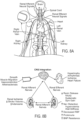
- FIG. 1 is a partially schematic illustration of a therapeutic system 100 (“system 100") configured in accordance with an embodiment of the present technology.
- the system 100 can include a neuromodulation device 102 (e.g., a neuromodulation catheter), a console 104, and a cable 106 extending therebetween.
- the neuromodulation device 102 can include an elongated shaft 108 having a proximal end portion 108a and a distal end portion 108b.
- a mandrel can define the shaft 108 or a portion thereof.
- a handle 110 of the neuromodulation device 102 can be operably connected to the shaft 108 via the proximal end portion 108a, and a neuromodulation assembly 112 can be operably connected to the shaft 108 via the distal end portion 108b.
- the neuromodulation assembly 112 can include one or more energy delivery elements (identified individually as a first energy delivery element 124a and a second energy delivery element 124b, and referred to collectively as energy delivery elements 124), such as a plurality of electrodes.
- the neuromodulation assembly 112 can include a single-electrode configuration, such as that described in International Patent Application No. PCT/US2009/069334 ( International Patent Application Publication No. WO 2010/078175), filed December 22, 2009 .
- the second energy delivery element 124b is illustrated in broken lines to indicate that the systems and methods disclosed herein can be used with neuromodulation devices having one or more energy delivery elements 124.
- the neuromodulation device 102 may include additional energy delivery elements 124 (e.g., four electrodes, five electrodes, six electrodes, etc.).
- the neuromodulation assembly 112 can be configured to have a spiral/helical shape with a plurality of energy delivery elements 124 positioned thereon. The spiral/helical shape may be at least partially straightened by a guide wire for delivery to a target site over the guide wire.
- the guide wire may be at least partially proximally withdrawn to thereby allow the neuromodulation assembly 112 to reassume its spiral/helical shape.
- suitable multi-electrode neuromodulation assemblies 112 are described in U.S. Patent Application No. 13/281,360 , published as US 2012-0116382 A1, filed October 25, 2011 , and U.S. Patent Application No. 13/793,647 , published as US 2013-0304061 A1, filed March 11, 2013 .
- shaft 108 can be incorporated with neuromodulation assemblies having different structural configurations and/or may include one or more energy delivery elements 124 other than electrodes.
- the shaft 108 can be incorporated with neuromodulation assemblies disclosed in International Patent Application No. PCT/US2011/057153 ( International Patent Application Publication No. WO2012/054862 ), U.S. Patent Application No. 13/826,604 , U.S. Patent Application No. 12/940,922 ( U.S. Patent Publication No. 2011/0112400 ), International Patent Application No. PCT/US2011/057514 , and U.S. Patent Application No. 13/458,859 , each of which is incorporated herein by reference in its entirety.
- the shaft 108 can be configured to locate the neuromodulation assembly 112 intravascularly at a treatment location within or otherwise proximate to a body lumen (e.g., a blood vessel, a duct, an airway, or another naturally occurring lumen within the human body), and the neuromodulation assembly 112 can be configured to provide or support a neuromodulation treatment at the treatment location (e.g., a treatment site within the renal arteries).
- a body lumen e.g., a blood vessel, a duct, an airway, or another naturally occurring lumen within the human body
- the shaft 108 and the neuromodulation assembly 112 can be 2, 3, 4, 5, 6, or 7 French or one or more other suitable sizes.
- intravascular delivery of the neuromodulation device 102 includes percutaneously inserting a guide wire (not shown) into a body lumen of a patient and moving the shaft 108 and the neuromodulation assembly 112 along the guide wire until the neuromodulation assembly 112 reaches a suitable treatment location (e.g., a renal artery).
- a suitable treatment location e.g., a renal artery.
- the distal end of the neuromodulation assembly 112 may define a passageway for engaging a guide wire (not shown) for delivery of the neuromodulation assembly 112 using over-the-wire ("OTW") or rapid exchange ("RX”) techniques.
- OGW over-the-wire
- RX rapid exchange
- the neuromodulation device 102 can be a steerable or non-steerable device configured for use without a guide wire.
- the neuromodulation device 102 can be configured for delivery via a guide catheter or sheath (not shown).
- the console 104 can be configured to control, monitor, supply, and/or otherwise support operation of the neuromodulation device 102.
- the neuromodulation device 102 can be self-contained or otherwise configured for operation without connection to the console 104.
- the console 104 can be configured to generate a selected form and/or magnitude of energy for delivery to tissue at the treatment location via the neuromodulation assembly 112 (e.g., via the energy delivery elements 124).
- the console 104 can have different configurations depending on the treatment modality of the neuromodulation device 102.
- the console 104 can include an energy generator (not shown) configured to generate radio frequency (RF) energy (e.g., monopolar and/or bipolar RF energy), pulsed energy, microwave energy, optical energy, ultrasound energy (e.g., intravascularly delivered ultrasound, high-intensity focused ultrasound (HIFU), and/or other types of ultrasound), cryotherapeutic energy, direct heat energy, chemicals (e.g., drugs and/or other agents), radiation (e.g., infrared, visible, and/or gamma radiation), and/or another suitable type of energy.
- RF radio frequency
- the console 104 can include a refrigerant reservoir (not shown) and can be configured to supply the neuromodulation device 102 with refrigerant.
- the console 104 can include a chemical reservoir (not shown) and can be configured to supply the neuromodulation device 102 with one or more chemicals.
- the system 100 includes a control device 114 communicatively coupled to the neuromodulation device 102.
- the control device 114 can be configured to initiate, terminate, and/or adjust operation of one or more components of the neuromodulation device 102 directly and/or via the console 104. In other embodiments, the control device 114 can be omitted or have other suitable locations (e.g., within the handle 110, along the cable 106, etc.).
- the console 104 can be configured to execute an automated control algorithm 116 and/or to receive control instructions from an operator. Further, the console 104 can be configured to provide feedback to an operator before, during, and/or after a treatment procedure via an evaluation/feedback algorithm 118.
- FIG. 2A is an enlarged side view of distal and proximal portions of the neuromodulation device 102 of FIG. 1 configured in accordance with an embodiment of the present technology.
- the shaft 108 extends proximally from a proximal portion 120a of a transition member 120, and the neuromodulation assembly 112 extends distally from a distal portion 120b of the transition member 120.
- the shaft 108 includes a solid-core mandrel 136 extending through at least a portion of its length to increase the axial and/or torsional stiffness of the shaft 108, while still maintaining sufficient flexibility to navigate the shaft 108 through tortuous anatomy.
- the distal end portion 108b of the shaft 108 can be attached to the proximal portion 120a of the transition member 120 at an attachment site 122 via an adhesive bond and/or other suitable types of attachment mechanisms (e.g., sutures, welding, etc.)
- This proximally-positioned attachment site 122 may be referred to as a "conversion bond” or "exchange bond” as it is located proximate to the transition to the distal-most section of the neuromodulation device 102.
- the shaft 108 can extend through at least a portion of the transition member 120 to further enhance the axial and/or torsional control the operator has over the neuromodulation assembly 112.
- the transition member 120 can be made from a low-profile braided material that is configured to increase the stability and control at the junction between the shaft 108 and the neuromodulation assembly 112.
- the braided material for example, can be made from para-aramid synthetic fiber sold under the trademark KEVLAR, polyether ether ketone (PEEK) polymer, and/or other suitable materials that enhance the stability of the transition member 120.
- the overall length of the transition member 120 can be about 5-25 cm (1.97-9.84 inches) (e.g., 10 cm (3.94 inches), 15 cm (5.91 inches), 20 cm (7.87 inches), etc.) depending upon the desired level of control, stiffness, and/or other suitable properties.
- the transition member 120 can have other suitable lengths and/or can be made from other suitable materials (e.g., non-braided polymer tubing). In further embodiments, the transition member 120 may be omitted, and the distal end portion 108b of the shaft 108 can be integrally formed with or attached to the neuromodulation assembly 112.
- the neuromodulation assembly 112 can include a guide wire channel or lumen 126 extending along its length and proximally through the transition member 120.
- the guide wire lumen 126 has a distal opening 128 at a distal end portion of the neuromodulation assembly 112 and a proximal opening 130 proximate to the proximal portion 120a of the transition member 120.
- the neuromodulation assembly 112 can be threaded over a guide wire (not shown), and the guide wire can extend proximally from the transition member 120.
- This configuration facilitates delivery to a treatment site using RX delivery techniques because the guide wire only extends through a portion of the neuromodulation device 102 (rather than along the entire length of the shaft 108).
- the neuromodulation assembly 112 has a spiral shape with a plurality of energy delivery elements 124 (identified individually as first through third energy delivery elements 124a-c, respectively) spaced apart from one another along the length of the neuromodulation assembly 112.
- the energy delivery elements 124 can be electrodes, transducers, and/or other types of energy delivery elements suitable for modulation of neural fibers.
- the neuromodulation assembly 112 can include fewer or more than three energy delivery elements 124, and/or have other suitable shapes or arrangements.
- FIG. 2B is an enlarged exploded cross-sectional view of a portion of the shaft 108 of FIG. 2A configured in accordance with an embodiment of the present technology.
- the shaft 108 includes the solid-core mandrel 136 and a plurality of energy delivery wires (identified individually as first and second energy delivery wires 138a and 138b, respectively, and referred to collectively as energy delivery wires 138) disposed within an outer covering/sheath or wall 134 and extending along a longitudinal axis A-A of the shaft 108.
- the mandrel 136 may be disposed along the entire length of the shaft 108 (e.g., from the proximal end portion 108a to the distal end portion 108b ( FIG.
- the mandrel 136 can have a substantially constant outer diameter along the length of the shaft 108. In other embodiments (such as the embodiments described below with reference to FIG. 3 ), the diameter of the mandrel 136 may differ along longitudinal segments of the shaft 108.
- the mandrel 136 can provide axial stiffness (e.g., pushability or other responsiveness to axial force) and/or torsional stiffness (e.g., torqueability or other responsiveness to torsional force) to the shaft 108 without compromising flexibility.
- the mandrel 136 can be made of a relatively strong material (e.g., nitinol, stainless steel, or other suitable metals) having an outer diameter of, for example, about 0.051-0.076 cm (0.02-0.03 inch) (e.g., 0.956 cm (0.022 inch), 0.051 cm (0.024 inch), 0.071 cm (0.028 inch), etc.).
- Such mandrels have been shown to exhibit greater flexibility (e.g., as determined by a three point bending flexural test) than hypotubes (e.g., hypotubes having an outer diameter of 0.081 cm (0.32 inch) and an inner diameter of 0.063 cm (0.025 inch)).
- the enhanced flexibility and increased control of pushability (e.g., axial stiffness) and torqueability (e.g., torsional stiffness) provided by the mandrel 136 can facilitate delivery of the neuromodulation assembly 112 ( FIG. 2A ) to a treatment site via tortuous intravascular paths (e.g., a transradial approach to a renal artery of a human patient).
- the increased flexibility and control provided by the mandrel 136 is not expected to unduly increase the overall outer diameter of the shaft 108.
- the neuromodulation device 102 ( FIGS. 1 and 2A ) can be introduced via a 5F guide catheter.
- the neuromodulation device 102 can be percutaneously introduced into the body using larger or smaller introducer devices.
- longitudinal segments of the mandrel 136 can be configured to have varying flexibilities, axial and/or torsional stiffnesses, and/or other physical properties.
- heat treatments can be applied to discrete sections of the mandrel 136 to change (e.g., optimize) flexibility of certain portions of the mandrel 136.
- annealing discrete longitudinal segments of the mandrel 136 will change the molecular structure of the mandrel material to make the annealed segment more flexible (e.g., less resistant to deflection in response to lateral force), whereas cold working (e.g., drawing and quenching) discrete segments of the mandrel 136 is expected to change the molecular structure to make the mandrel 136 stiffer.
- different or additional processes can be applied to longitudinal segments of the mandrel 136 to change desired physical properties of the material. As described in further detail below with reference to FIG.
- the outer diameter of longitudinal segments of the mandrel 136 can be varied (e.g., tapered) to increase/decrease the flexibility of certain portions of the mandrel 136. Accordingly, portions of the mandrel 136 can be configured to have varying degrees of flexibility (e.g., to facilitate intravascular delivery of a neuromodulation assembly to a treatment location within or otherwise proximate to a renal artery of a human patient via a transradial or other suitable approach).
- the energy delivery wires 138 can extend through the length of the shaft 108 along the side of the mandrel 136.
- the energy delivery wires 138 can be operably coupled to the energy delivery elements 124 ( FIG. 2A ) at a distal end of the neuromodulation device 102, and an energy delivery device (e.g., the console 104 of FIG. 1 ) coupled to a proximal end of the neuromodulation device 102 and external to a patient.
- the energy delivery wires 138 can be arranged in other suitable configurations along the length of the shaft 108.
- the energy delivery wires 138 can be wrapped around the mandrel 136 in a helical pattern.
- one energy delivery wire 138 can delivery energy to an energy delivery element 124 ( FIG. 2A ), and the other energy delivery wire 138 can detect temperature proximate to the treatment site.
- each energy delivery wire 138 can correspond to an individual energy delivery element 124 ( FIG. 2A ) of the neuromodulation assembly 112 to provide for independent control of the energy delivery elements 124.
- the shaft 108 can include other types of wires configured to provide heat-element-based or transducer-based treatment via the neuromodulation assembly 112 (e.g., cryotherapeutic treatment, direct heat treatment, etc.). The shaft 108 can additionally or alternatively include additional wires or lines for detecting various parameters at the treatment site and/or otherwise associated with operation of the neuromodulation device 102.
- the energy delivery wires 138, mandrel 136, and other components of the shaft 108 can be encapsulated by the outer wall 134 to electrically insulate and protect the elements from the external environment.
- the outer wall 134 can be made from a thin layer of polymer material, e.g., with a thickness of about 0.025-0.003 cm (0.01-0.001 inch), and formed using an overjackting process (e.g., overjacketing extrusion) in which the mandrel 136 and other elements extending along the shaft 108 (e.g., the energy delivery wires 138) are pulled through the center of a die.
- the outer wall 134 can be made from other electrically isolative materials suitable for encapsulating the mandrel 136 and other shaft elements and suitable for insertion into a human patient.
- FIG. 3 is an enlarged partial side view of a distal portion of a neuromodulation device 302 configured in accordance with another embodiment of the present technology.
- the neuromodulation device 302 can include several features generally similar in structure and/or function as the features of the neuromodulation device 102 described above with respect to FIGS. 1-2B .
- the neuromodulation device 302 includes the elongated shaft 108 with the distal end portion 108b operably coupled to a neuromodulation assembly 112 and the transition member 120 with the guide wire lumen 126 to facilitate RX guide wire delivery of the neuromodulation assembly 112 to a treatment site.
- the neuromodulation device 302 further includes a mandrel 336 (e.g., encased in a polymer overjacket) extending along at least a portion of the elongated shaft 108. Similar to the mandrel 136 described above with respect to FIGS. 2A and 2B , the mandrel 336 of FIG. 3 can enhance the axial and/or torsional stiffness of the shaft 108 without compromising the flexibility of the shaft 108 and, therefore, facilitate delivery of the neuromodulation assembly 112 to a treatment site along tortuous intravascular paths (e.g., transradial delivery to the renal arteries).
- tortuous intravascular paths e.g., transradial delivery to the renal arteries.
- the mandrel 336 includes a plurality of stepped longitudinal segments or portions (identified individually as first to third stepped portions 340a-c, respectively, and referred to collectively as stepped portions 340) that have decreasingly smaller outer diameters toward the distal end of the shaft 108.
- the mandrel 336 includes three stepped portions 340 and tapered transition regions 342 between each stepped portion 340 (e.g., formed using a sandless grinding process, laser cutting, etc.).
- the mandrel 336 may include two stepped portions 340, more than three stepped portions 340, and/or the transition regions 342 may have different configurations (e.g., a hard step between each stepped portion 340).
- the third stepped portion 340c has the smallest outer diameter and, therefore, is more flexible than the first and second stepped portions 340a and 340b. Accordingly, the outer diameter of longitudinal segments of the mandrel 336 can be selected to provide varying degrees of flexibilities at specific portions of the mandrel 336.
- the mandrel 336 can have a continuous taper along its entire length (e.g., using laser cutting techniques) or along discrete portions of the mandrel 336 to gradually increase the flexibility of the mandrel 336 toward the distal or proximal end.
- the mandrel 336 can include other structural features that alter the flexibility of discrete portions of the mandrel 336.
- the mandrel 336 can extend through at least a portion of the transition member 120 and can be attached at a bond site 322 proximate to the distal portion 120b of the transition member 120. In other embodiments, the mandrel 336 can extend to an intermediate portion of the transition member 120. This elongated mandrel 336 can increase the push and/or torsional efficiency of the shaft 108 by providing enhanced axial and/or torsional stiffness along the transition member 120. As shown in FIG. 3 , the mandrel 336 can be tapered to a small outer diameter so as not to substantially increase the overall diameter of the transition member 120 and, therefore, facilitate low-profile intravascular delivery to a treatment site with increased distal control.
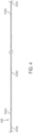
- FIG. 4 is a side view of a mandrel 436 of a neuromodulation device (e.g., the neuromodulation device 102 described above) configured in accordance with yet another embodiment of the present technology.
- the mandrel 436 can define at least a portion of the shaft of the neuromodulation device.
- the mandrel 436 can define a proximal portion of the shaft extending from a handle to a transitional or intermediate shaft, which in turn connects to a neuromodulation assembly.
- the intermediate shaft can be made of a braided polymer and transition the shaft from the mandrel 436 to the neuromodulation assembly (e.g., for RX-type guidewire delivery).
- the mandrel 436 can have a length of about 130-160 cm (51-63 inches) (e.g., 152 cm (60 inches)) to allow the mandrel 436 to extend through a substantial portion of a patient's vasculature (e.g., from a radial artery insertion site, through the arteries of the upper limb to the descending aorta).
- the mandrel 436 may be longer or shorter depending on various factors, such as the patient's anatomy and/or the navigation path of the shaft, and/or the mandrel 436 may extend along different portions of the shaft.
- the mandrel 436 of FIG. 4 can have a solid core, and can be encased in a polymer overjacket.
- the mandrel 436 can have differently sized outer diameters along longitudinal portions of the mandrel 436, and the outer diameters of the longitudinal portions may decrease toward the distal end of the mandrel 436.
- the mandrel 436 includes two tapered sections or zones (identified individually as a first tapered zone 442a and a second tapered zone 442b, and referred to collectively as tapered zones 442) that separate longitudinal segments (identified individually as a proximal longitudinal segment 444a, an intermediate longitudinal segment 444b, and a distal longitudinal segment 444c, and referred to collectively as longitudinal segments 444) of the mandrel 436.
- Each longitudinal segment 444 can have a different outer diameter, with the proximal longitudinal segment 444a having the largest outer diameter, the distal longitudinal segment 444c having the smallest outer diameter, and the intermediate longitudinal segment 444b having an outer diameter scaled between the outer diameters of the proximal and distal longitudinal segments 444a and 444c.
- the proximal longitudinal segment 444a can have an outer diameter of about 0.4-0.8 mm (0.016-0.031 inch) (e.g., 0.510 mm (0.020 inch)), the distal longitudinal segment 444c can have outer diameter of about 0.1-0.4 mm (0.004-0.016 inch) (e.g., 0.254 mm (0.010 inch)), and the intermediate longitudinal segment 444b can have outer diameter of about 0.3-0.6 mm (0.012-0.024 inch) (e.g., 0.457 mm (0.018 inch)).
- This configuration is expected to provide increased flexibility toward the distal end of the mandrel 436.
- the distal longitudinal segment 444c with its small outer diameter can extend at least partially into an intermediate shaft portion (e.g., the transition member 120 described above) to provide a smooth transition in bending stiffness at the exchange joint (i.e., between the proximal portion of the shaft and the intermediate portion of the shaft).
- an intermediate shaft portion e.g., the transition member 120 described above
- the tapered zones 442 can have a constant taper from the outer diameter of one longitudinal segment 444 to the adjacent longitudinal segment 444.
- the tapered zones 442 can be formed by grinding and/or other suitable manufacturing techniques.
- each tapered zone 442 can have a length of about 3-16 mm (0.12-0.63 inch) (e.g., 9.906 mm (0.390 inch)). In other embodiments, however, the tapered zones 442 can be longer or shorter and/or the individual tapered zones 442 can have differing lengths.
- the tapered mandrel 436 is expected to enhance the trackability of the shaft by tuning the mandrel's flexibility for navigating selected portions within the anatomy.
- the distal portion of the mandrel 436 may be required to extend through more tortuous portions of the vasculature (e.g., small vessels) than the intermediate or proximal portions of the mandrel 436, and therefore the length and the outer diameter of the distal longitudinal segment 444c can be selected to provide sufficient flexibility for its specific application.
- the outer diameters and lengths of the intermediate and proximal longitudinal segments 444b and 444a can be selected based the portions of the vasculature they are intended to navigate.
- the mandrel 436 can include more than three or fewer than three longitudinal segments 444 with differing outer diameters and/or lengths to provide the desired flexibility throughout the shaft for a specific application.
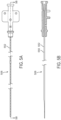
- FIG. 5A is a side view of a portion of a shaft 508 of a neuromodulation device (e.g., the neuromodulation device 102 described above) configured in accordance with a further embodiment of the present technology.
- FIG. 5B is a longitudinal cross-sectional view of the shaft 508 taken along line 5B-5B of FIG. 5A
- FIG. 5C is an enlarged view of a distal section of the shaft 508 of FIGS. 5A and 5B .
- the shaft 508 can include a hypotube 550 ( FIG.
- the hypotube 550 can extend through about two thirds of the length of the shaft 508 (e.g., about 101-154 cm (40-60 inches)). In other embodiments, however, the hypotube 550 can extend through longer or shorter portions of the shaft 508. As shown in FIG.
- the hypotube 550 can extend distally from the outer jacket 552 and have a tapered or oblique opening (e.g., about 0.500 cm (0.20 inch) in length) such that the hypotube 550 thins to a semi-circular structure (e.g., about 2.0 cm (0.80 inch) in length).
- the distal exposed portion of the hypotube 550 can be about 2-4 cm (0.80-1.6 inches) (e.g., 2.2 cm (0.866 inch)) in length.
- This distal end portion may extend into an intermediate shaft portion (e.g., the transition member 120 described above), connect directly to a neuromodulation assembly at the distal end of the shaft 508, and/or attach to another portion of the shaft 508.
- the outer diameter of the shaft 508 (e.g., the outer diameter of the outer jacket 552) can be about 0.75-1.5 mm (0.03-0.06 inch) (e.g., 0.914 mm (0.036 inch))
- the outer diameter of the hypotube 550 can be about 0.5-1.0 mm (0.02-0.04 inch) (e.g., 0.813 mm (0.032 inch))
- the inner diameter of the hypotube 550 can be about 0.3-0.75 mm (0.01-0.03 inch) (e.g., 0.635 mm (0.025 inch)).
- the inner diameter of the hypotube 550 can be selected to house various components of the neuromodulation device (e.g., electrical wires) and/or allow for instrument throughput.
- the hypotube 550 can provide a lumen through which a guidewire can be extended to facilitate delivery of the shaft 508 to a treatment site within the vasculature of a human patient and/or facilitate deployment of a neuromodulation assembly at a distal portion of the shaft 508.
- the outer jacket 552 and/or the hypotube 550 can have other suitable dimensions.
- the hypotube 550 can be made from nitinol and laser cut to the desired configuration.
- a nitinol hypotube is expected to provide enhanced torque control relative to a number of conventional stainless steel hypotubes by having sufficient torsional stiffness while its stress induced martensite (SIM) property provides superelasticity for a high degree of kink resistance to navigate through tortuous vasculature.
- SIM stress induced martensite
- the hypotube 550 can be made from other suitable materials that impart trackability to the shaft 508 without compromising flexibility.
- the hypotube 550 or portions thereof can be formulated and/or heat treated or otherwise prepared or tuned to provide desired characteristics, such as a specific degree of flexibility.
- a distal portion of the hypotube 550 e.g., having a length of about 50 cm (19.69 inches)
- Nitinol for example, can be formulated and/or prepared to have an austenite finish temperature (A f ) suited for operation at body temperature.
- a distal portion of the nitinol hypotube 550 can be tuned to have a desired flexibility and SIM capability at body temperature to enhance its performance through tortuous anatomy (e.g., the portion of a transradial access route to the renal arteries that extends through the subclavian artery), and the proximal portion of the hypotube 550 can remain more stiff in an austenite phase.
- longitudinal segments of the hypotube 550 can be tuned to have other desired material properties depending on the specific application.
- Renal neuromodulation is the partial or complete incapacitation or other effective disruption of nerves of the kidneys (e.g., nerves terminating in the kidneys or in structures closely associated with the kidneys).
- renal neuromodulation can include inhibiting, reducing, and/or blocking neural communication along neural fibers (e.g., efferent and/or afferent neural fibers) of the kidneys.
- Such incapacitation can be long-term (e.g., permanent or for periods of months, years, or decades) or short-term (e.g., for periods of minutes, hours, days, or weeks).
- Renal neuromodulation is expected to contribute to the systemic reduction of sympathetic tone or drive and/or to benefit at least some specific organs and/or other bodily structures innervated by sympathetic nerves. Accordingly, renal neuromodulation is expected to be useful in treating clinical conditions associated with systemic sympathetic overactivity or hyperactivity, particularly conditions associated with central sympathetic overstimulation. For example, renal neuromodulation is expected to efficaciously treat hypertension, heart failure, acute myocardial infarction, metabolic syndrome, insulin resistance, diabetes, left ventricular hypertrophy, chronic and end stage renal disease, inappropriate fluid retention in heart failure, cardio-renal syndrome, polycystic kidney disease, polycystic ovary syndrome, osteoporosis, erectile dysfunction, and sudden death, among other conditions.
- Renal neuromodulation can be electrically-induced, thermally-induced, chemically-induced, or induced in another suitable manner or combination of manners at one or more suitable treatment locations during a treatment procedure.
- the treatment location can be within or otherwise proximate to a renal lumen (e.g., a renal artery, a ureter, a renal pelvis, a major renal calyx, a minor renal calyx, or another suitable structure), and the treated tissue can include tissue at least proximate to a wall of the renal lumen.
- a treatment procedure can include modulating nerves in the renal plexus, which lay intimately within or adjacent to the adventitia of the renal artery.
- Renal neuromodulation can include a cryotherapeutic treatment modality alone or in combination with another treatment modality.
- Cryotherapeutic treatment can include cooling tissue at a treatment location in a manner that modulates neural function.
- sufficiently cooling at least a portion of a sympathetic renal nerve can slow or potentially block conduction of neural signals to produce a prolonged or permanent reduction in renal sympathetic activity.
- cryotherapeutic tissue damage can include, for example, direct cell injury (e.g., necrosis), vascular or luminal injury (e.g., starving cells from nutrients by damaging supplying blood vessels), and/or sublethal hypothermia with subsequent apoptosis.
- Exposure to cryotherapeutic cooling can cause acute cell death (e.g., immediately after exposure) and/or delayed cell death (e.g., during tissue thawing and subsequent hyperperfusion).
- Neuromodulation using a cryotherapeutic treatment in accordance with embodiments of the present technology can include cooling a structure proximate an inner surface of a body lumen wall such that tissue is effectively cooled to a depth where sympathetic renal nerves reside.
- a cooling assembly of a cryotherapeutic device can be cooled to the extent that it causes therapeutically-effective, cryogenic renal neuromodulation.
- a cryotherapeutic treatment modality can include cooling that is not configured to cause neuromodulation.
- the cooling can be at or above cryogenic temperatures and can be used to control neuromodulation via another treatment modality (e.g., to protect tissue from neuromodulating energy).
- Renal neuromodulation can include an electrode-based or transducer-based treatment modality alone or in combination with another treatment modality.
- Electrode-based or transducer-based treatment can include delivering electricity and/or another form of energy to tissue at a treatment location to stimulate and/or heat the tissue in a manner that modulates neural function. For example, sufficiently stimulating and/or heating at least a portion of a sympathetic renal nerve can slow or potentially block conduction of neural signals to produce a prolonged or permanent reduction in renal sympathetic activity.
- a variety of suitable types of energy can be used to stimulate and/or heat tissue at a treatment location.
- neuromodulation in accordance with embodiments of the present technology can include delivering RF energy, pulsed energy, microwave energy, optical energy, focused ultrasound energy (e.g., high-intensity focused ultrasound energy), or another suitable type of energy alone or in combination.
- An electrode or transducer used to deliver this energy can be used alone or with other electrodes or transducers in a multi-electrode or multi-transducer array.
- the energy can be applied from within the body (e.g., within the vasculature or other body lumens in a catheter-based approach) and/or from outside the body (e.g., via an applicator positioned outside the body).
- energy can be used to reduce damage to non-targeted tissue when targeted tissue adjacent to the non-targeted tissue is subjected to neuromodulating cooling.
- Focused ultrasound is an example of a transducer-based treatment modality that can be delivered from outside the body. Focused ultrasound treatment can be performed in close association with imaging (e.g., magnetic resonance, computed tomography, fluoroscopy, ultrasound (e.g., intravascular or intraluminal), optical coherence tomography, or another suitable imaging modality). For example, imaging can be used to identify an anatomical position of a treatment location (e.g., as a set of coordinates relative to a reference point).
- imaging can be used to identify an anatomical position of a treatment location (e.g., as a set of coordinates relative to a reference point).
- the coordinates can then entered into a focused ultrasound device configured to change the power, angle, phase, or other suitable parameters to generate an ultrasound focal zone at the location corresponding to the coordinates.
- the focal zone can be small enough to localize therapeutically-effective heating at the treatment location while partially or fully avoiding potentially harmful disruption of nearby structures.
- the ultrasound device can be configured to pass ultrasound energy through a lens, and/or the ultrasound energy can be generated by a curved transducer or by multiple transducers in a phased array (curved or straight).
- Heating effects of electrode-based or transducer-based treatment can include ablation and/or non-ablative alteration or damage (e.g., via sustained heating and/or resistive heating).
- a treatment procedure can include raising the temperature of target neural fibers to a target temperature above a first threshold to achieve non-ablative alteration, or above a second, higher threshold to achieve ablation.
- the target temperature can be higher than about body temperature (e.g., about 37°C) but less than about 45°C for non-ablative alteration, and the target temperature can be higher than about 45°C for ablation.
- Heating tissue to a temperature between about body temperature and about 45°C can induce non-ablative alteration, for example, via moderate heating of target neural fibers or of vascular or luminal structures that perfuse the target neural fibers. In cases where vascular structures are affected, the target neural fibers can be denied perfusion resulting in necrosis of the neural tissue. Heating tissue to a target temperature higher than about 45°C (e.g., higher than about 60°C) can induce ablation, for example, via substantial heating of target neural fibers or of vascular or luminal structures that perfuse the target fibers.
- tissue it can be desirable to heat tissue to temperatures that are sufficient to ablate the target neural fibers or the vascular or luminal structures, but that are less than about 90°C (e.g., less than about 85°C, less than about 80°C, or less than about 75°C).
- Renal neuromodulation can include a chemical-based treatment modality alone or in combination with another treatment modality.
- Neuromodulation using chemical-based treatment can include delivering one or more chemicals (e.g., drugs or other agents) to tissue at a treatment location in a manner that modulates neural function.
- the chemical for example, can be selected to affect the treatment location generally or to selectively affect some structures at the treatment location over other structures.
- the chemical for example, can be guanethidine, ethanol, phenol, a neurotoxin, or another suitable agent selected to alter, damage, or disrupt nerves.
- a variety of suitable techniques can be used to deliver chemicals to tissue at a treatment location.
- chemicals can be delivered via one or more needles originating outside the body or within the vasculature or other body lumens.
- a catheter can be used to intravascularly position a therapeutic element including a plurality of needles (e.g., micro-needles) that can be retracted or otherwise blocked prior to deployment.
- a chemical can be introduced into tissue at a treatment location via simple diffusion through a body lumen wall, electrophoresis, or another suitable mechanism. Similar techniques can be used to introduce chemicals that are not configured to cause neuromodulation, but rather to facilitate neuromodulation via another treatment modality.
- the sympathetic nervous system is a branch of the autonomic nervous system along with the enteric nervous system and parasympathetic nervous system. It is always active at a basal level (called sympathetic tone) and becomes more active during times of stress.
- the sympathetic nervous system operates through a series of interconnected neurons. Sympathetic neurons are frequently considered part of the peripheral nervous system (PNS), although many lie within the central nervous system (CNS).
- Sympathetic neurons of the spinal cord (which is part of the CNS) communicate with peripheral sympathetic neurons via a series of sympathetic ganglia. Within the ganglia, spinal cord sympathetic neurons join peripheral sympathetic neurons through synapses. Spinal cord sympathetic neurons are therefore called presynaptic (or preganglionic) neurons, while peripheral sympathetic neurons are called postsynaptic (or postganglionic) neurons.
- preganglionic sympathetic neurons release acetylcholine, a chemical messenger that binds and activates nicotinic acetylcholine receptors on postganglionic neurons.
- postganglionic neurons principally release noradrenaline (norepinephrine). Prolonged activation may elicit the release of adrenaline from the adrenal medulla.
- norepinephrine and epinephrine bind adrenergic receptors on peripheral tissues. Binding to adrenergic receptors causes a neuronal and hormonal response. The physiologic manifestations include pupil dilation, increased heart rate, occasional vomiting, and increased blood pressure. Increased sweating is also seen due to binding of cholinergic receptors of the sweat glands.
- the sympathetic nervous system is responsible for up- and down-regulating many homeostatic mechanisms in living organisms. Fibers from the SNS innervate tissues in almost every organ system, providing at least some regulatory function to physiological features as diverse as pupil diameter, gut motility, and urinary output. This response is also known as sympatho-adrenal response of the body, as the preganglionic sympathetic fibers that end in the adrenal medulla (but also all other sympathetic fibers) secrete acetylcholine, which activates the secretion of adrenaline (epinephrine) and to a lesser extent noradrenaline (norepinephrine). Therefore, this response that acts primarily on the cardiovascular system is mediated directly via impulses transmitted through the sympathetic nervous system and indirectly via catecholamines secreted from the adrenal medulla.
- the SNS provides a network of nerves that allows the brain to communicate with the body.
- Sympathetic nerves originate inside the vertebral column, toward the middle of the spinal cord in the intermediolateral cell column (or lateral horn), beginning at the first thoracic segment of the spinal cord and are thought to extend to the second or third lumbar segments. Because its cells begin in the thoracic and lumbar regions of the spinal cord, the SNS is said to have a thoracolumbar outflow. Axons of these nerves leave the spinal cord through the anterior rootlet/root. They pass near the spinal (sensory) ganglion, where they enter the anterior rami of the spinal nerves.
- the axons In order to reach the target organs and glands, the axons should travel long distances in the body, and, to accomplish this, many axons relay their message to a second cell through synaptic transmission. The ends of the axons link across a space, the synapse, to the dendrites of the second cell. The first cell (the presynaptic cell) sends a neurotransmitter across the synaptic cleft where it activates the second cell (the postsynaptic cell). The message is then carried to the final destination.
- ganglia In the SNS and other components of the peripheral nervous system, these synapses are made at sites called ganglia, discussed above.
- the cell that sends its fiber is called a preganglionic cell, while the cell whose fiber leaves the ganglion is called a postganglionic cell.
- the preganglionic cells of the SNS are located between the first thoracic (T1) segment and third lumbar (L3) segments of the spinal cord.
- Postganglionic cells have their cell bodies in the ganglia and send their axons to target organs or glands.
- the ganglia include not just the sympathetic trunks but also the cervical ganglia (superior, middle and inferior), which sends sympathetic nerve fibers to the head and thorax organs, and the celiac and mesenteric ganglia (which send sympathetic fibers to the gut).
- the kidney is innervated by the renal plexus (RP), which is intimately associated with the renal artery.
- the renal plexus (RP) is an autonomic plexus that surrounds the renal artery and is embedded within the adventitia of the renal artery.
- the renal plexus (RP) extends along the renal artery until it arrives at the substance of the kidney. Fibers contributing to the renal plexus (RP) arise from the celiac ganglion, the superior mesenteric ganglion, the aorticorenal ganglion and the aortic plexus.
- the renal plexus (RP) also referred to as the renal nerve, is predominantly comprised of sympathetic components. There is no (or at least very minimal) parasympathetic innervation of the kidney.
- Preganglionic neuronal cell bodies are located in the intermediolateral cell column of the spinal cord. Preganglionic axons pass through the paravertebral ganglia (they do not synapse) to become the lesser splanchnic nerve, the least splanchnic nerve, first lumbar splanchnic nerve, second lumbar splanchnic nerve, and travel to the celiac ganglion, the superior mesenteric ganglion, and the aorticorenal ganglion. Postganglionic neuronal cell bodies exit the celiac ganglion, the superior mesenteric ganglion, and the aorticorenal ganglion to the renal plexus (RP) and are distributed to the renal vasculature.
- RP renal plexus
- Efferent messages may trigger changes in different parts of the body simultaneously.
- the sympathetic nervous system may accelerate heart rate; widen bronchial passages; decrease motility (movement) of the large intestine; constrict blood vessels; increase peristalsis in the esophagus; cause pupil dilation, piloerection (goose bumps) and perspiration (sweating); and raise blood pressure.
- Afferent messages carry signals from various organs and sensory receptors in the body to other organs and, particularly, the brain.
- renin-angiotensin-aldosterone system has been a longstanding, but somewhat ineffective, approach for reducing over-activity of the SNS.
- the renal sympathetic nervous system has been identified as a major contributor to the complex pathophysiology of hypertension, states of volume overload (such as heart failure), and progressive renal disease, both experimentally and in humans.
- Studies employing radiotracer dilution methodology to measure overflow of norepinephrine from the kidneys to plasma revealed increased renal norepinephrine (NE) spillover rates in patients with essential hypertension, particularly so in young hypertensive subjects, which in concert with increased NE spillover from the heart, is consistent with the hemodynamic profile typically seen in early hypertension and characterized by an increased heart rate, cardiac output, and renovascular resistance.
- NE renal norepinephrine
- Sympathetic nerves to the kidneys terminate in the blood vessels, the juxtaglomerular apparatus and the renal tubules. Stimulation of the renal sympathetic nerves causes increased renin release, increased sodium (Na + ) reabsorption, and a reduction of renal blood flow. These components of the neural regulation of renal function are considerably stimulated in disease states characterized by heightened sympathetic tone and clearly contribute to the rise in blood pressure in hypertensive patients. The reduction of renal blood flow and glomerular filtration rate as a result of renal sympathetic efferent stimulation is likely a cornerstone of the loss of renal function in cardio-renal syndrome, which is renal dysfunction as a progressive complication of chronic heart failure, with a clinical course that typically fluctuates with the patient's clinical status and treatment.
- Pharmacologic strategies to thwart the consequences of renal efferent sympathetic stimulation include centrally acting sympatholytic drugs, beta blockers (intended to reduce renin release), angiotensin converting enzyme inhibitors and receptor blockers (intended to block the action of angiotensin II and aldosterone activation consequent to renin release) and diuretics (intended to counter the renal sympathetic mediated sodium and water retention).
- the current pharmacologic strategies have significant limitations including limited efficacy, compliance issues, side effects and others.
- the kidneys communicate with integral structures in the central nervous system via renal sensory afferent nerves.
- renal injury may induce activation of sensory afferent signals.
- renal ischemia, reduction in stroke volume or renal blood flow, or an abundance of adenosine enzyme may trigger activation of afferent neural communication.
- this afferent communication might be from the kidney to the brain or might be from one kidney to the other kidney (via the central nervous system).
- These afferent signals are centrally integrated and may result in increased sympathetic outflow.
- This sympathetic drive is directed towards the kidneys, thereby activating the RAAS and inducing increased renin secretion, sodium retention, volume retention and vasoconstriction.
- Central sympathetic over activity also impacts other organs and bodily structures innervated by sympathetic nerves such as the heart and the peripheral vasculature, resulting in the described adverse effects of sympathetic activation, several aspects of which also contribute to the rise in blood pressure.
- renal denervation is likely to be valuable in the treatment of several clinical conditions characterized by increased overall and particularly renal sympathetic activity such as hypertension, metabolic syndrome, insulin resistance, diabetes, left ventricular hypertrophy, chronic end stage renal disease, inappropriate fluid retention in heart failure, cardio-renal syndrome, and sudden death.
- renal denervation might also be useful in treating other conditions associated with systemic sympathetic hyperactivity.
- renal denervation may also benefit other organs and bodily structures innervated by sympathetic nerves, including those identified in FIG. 6 .
- a reduction in central sympathetic drive may reduce the insulin resistance that afflicts people with metabolic syndrome and Type II diabetics.
- patients with osteoporosis are also sympathetically activated and might also benefit from the down regulation of sympathetic drive that accompanies renal denervation.
- neuromodulation of a left and/or right renal plexus may be achieved through intravascular access.
- FIG. 9A blood moved by contractions of the heart is conveyed from the left ventricle of the heart by the aorta.
- the aorta descends through the thorax and branches into the left and right renal arteries.
- Below the renal arteries the aorta bifurcates at the left and right iliac arteries.
- the left and right iliac arteries descend, respectively, through the left and right legs and join the left and right femoral arteries.
- the blood collects in veins and returns to the heart, through the femoral veins into the iliac veins and into the inferior vena cava.
- the inferior vena cava branches into the left and right renal veins. Above the renal veins, the inferior vena cava ascends to convey blood into the right atrium of the heart. From the right atrium, the blood is pumped through the right ventricle into the lungs, where it is oxygenated. From the lungs, the oxygenated blood is conveyed into the left atrium. From the left atrium, the oxygenated blood is conveyed by the left ventricle back to the aorta.
- the femoral artery may be accessed and cannulated at the base of the femoral triangle just inferior to the midpoint of the inguinal ligament.
- a catheter may be inserted percutaneously into the femoral artery through this access site, passed through the iliac artery and aorta, and placed into either the left or right renal artery. This comprises an intravascular path that offers minimally invasive access to a respective renal artery and/or other renal blood vessels.
- the wrist, upper arm, and shoulder region provide other locations for introduction of catheters into the arterial system.
- catheterization of either the radial, brachial, or axillary artery may be utilized in select cases.
- Catheters introduced via these access points may be passed through the subclavian artery on the left side (or via the subclavian and brachiocephalic arteries on the right side), through the aortic arch, down the descending aorta and into the renal arteries using standard angiographic technique.
- properties and characteristics of the renal vasculature may impose constraints upon and/or inform the design of apparatus, systems, and methods for achieving such renal neuromodulation. Some of these properties and characteristics may vary across the patient population and/or within a specific patient across time, as well as in response to disease states, such as hypertension, chronic kidney disease, vascular disease, end-stage renal disease, insulin resistance, diabetes, metabolic syndrome, etc. These properties and characteristics, as explained herein, may have bearing on the efficacy of the procedure and the specific design of the intravascular device. Properties of interest may include, for example, material/mechanical, spatial, fluid dynamic/hemodynamic and/or thermodynamic properties.
- a catheter may be advanced percutaneously into either the left or right renal artery via a minimally invasive intravascular path.
- minimally invasive renal arterial access may be challenging, for example, because as compared to some other arteries that are routinely accessed using catheters, the renal arteries are often extremely tortuous, may be of relatively small diameter, and/or may be of relatively short length.
- renal arterial atherosclerosis is common in many patients, particularly those with cardiovascular disease. Renal arterial anatomy also may vary significantly from patient to patient, which further complicates minimally invasive access.
- Sufficient energy should be delivered to or heat removed from the target renal nerves to modulate the target renal nerves without excessively cooling or heating the vessel wall to the extent that the wall is frozen, desiccated, or otherwise potentially affected to an undesirable extent.
- a potential clinical complication associated with excessive heating is thrombus formation from coagulating blood flowing through the artery. Given that this thrombus may cause a kidney infarct, thereby causing irreversible damage to the kidney, thermal treatment from within the renal artery should be applied carefully.
- the complex fluid mechanics and thermodynamic conditions present in the renal artery during treatment may be important in applying energy (e.g., heating thermal energy) and/or removing heat from the tissue (e.g., cooling thermal conditions) from within the renal artery.
- energy e.g., heating thermal energy
- tissue e.g., cooling thermal conditions
- the neuromodulatory apparatus should also be configured to allow for adjustable positioning and repositioning of the energy delivery element within the renal artery since location of treatment may also impact clinical efficacy. For example, it may be helpful to apply a full circumferential treatment from within the renal artery given that the renal nerves may be spaced circumferentially around a renal artery. In some situations, a full-circle lesion likely resulting from a continuous circumferential treatment may be potentially related to renal artery stenosis. Therefore, the formation of more complex lesions along a longitudinal dimension of the renal artery and/or repositioning of the neuromodulatory apparatus to multiple treatment locations may be desirable.
- a benefit of creating a circumferential ablation may outweigh the potential of renal artery stenosis or the risk may be mitigated with certain embodiments or in certain patients and creating a circumferential ablation could be a goal.
- variable positioning and repositioning of the neuromodulatory apparatus may prove to be useful in circumstances where the renal artery is particularly tortuous or where there are proximal branch vessels off the renal artery main vessel, making treatment in certain locations challenging.
- Manipulation of a device in a renal artery should also consider mechanical injury imposed by the device on the renal artery. Motion of a device in an artery, for example by inserting, manipulating, negotiating bends and so forth, may contribute to dissection, perforation, denuding intima, or disrupting the interior elastic lamina.
- Blood flow through a renal artery may be temporarily occluded for a short time with minimal or no complications.
- occlusion for a significant amount of time should be avoided because to prevent injury to the kidney such as ischemia. It could be beneficial to avoid occlusion all together or, if occlusion is beneficial to the embodiment, to limit the duration of occlusion, for example to 2-5 minutes.
- various independent and dependent properties of the renal vasculature include, for example, (a) vessel diameter, vessel length, intima-media thickness, coefficient of friction, and tortuosity, (b) distensibility, stiffness and modulus of elasticity of the vessel wall; (c) peak systolic, end-diastolic blood flow velocity, as well as the mean systolic-diastolic peak blood flow velocity, and mean/max volumetric blood flow rate; (d) specific heat capacity of blood and/or of the vessel wall, thermal conductivity of blood and/or of the vessel wall, and/or thermal convectivity of blood flow past a vessel wall treatment site and/or radiative heat transfer;
- Renal artery vessel diameter, D RA typically is in a range of about 2-10 mm, with most of the patient population having a D RA of about 4 mm to about 8 mm and an average of about 6 mm.
- Renal artery vessel length, L RA between its ostium at the aorta/renal artery juncture and its distal branchings, generally is in a range of about 5-70 mm, and a significant portion of the patient population is in a range of about 20-50 mm.
- the composite Intima-Media Thickness, IMT (i.e., the radial outward distance from the artery's luminal surface to the adventitia containing target neural structures) also is notable and generally is in a range of about 0.5-2.5 mm, with an average of about 1.5 mm. Although a certain depth of treatment is important to reach the target neural fibers, the treatment should not be too deep (e.g., > 5 mm from inner wall of the renal artery) to avoid non-target tissue and anatomical structures such as the renal vein.
- An additional property of the renal artery that may be of interest is the degree of renal motion relative to the aorta induced by respiration and/or blood flow pulsatility.
- a patient's kidney which is located at the distal end of the renal artery, may move as much as 4" cranially with respiratory excursion. This may impart significant motion to the renal artery connecting the aorta and the kidney, thereby requiring from the neuromodulatory apparatus a unique balance of stiffness and flexibility to maintain contact between the energy delivery element and the vessel wall during cycles of respiration.
- the take-off angle between the renal artery and the aorta may vary significantly between patients, and also may vary dynamically within a patient, e.g., due to kidney motion. The take-off angle generally may be in a range of about 30°-135°.
Claims (12)
- Dispositif de neuromodulation (102), comprenant :une tige allongée (108) ayant une partie d'extrémité distale (108b) et un mandrin (136) s'étendant au moins le long de la partie d'extrémité distale ;un élément de transition (120) ayant une partie proximale (120a), une partie distale (120b) et une lumière pour fil-guide (126) s'étendant à travers les parties proximale et distale, dans lequel la tige (108) s'étend de manière proximale à partir de la partie proximale (120a) de l'élément de transition (120), dans lequel l'élément de transition (120) est fabriqué à partir d'un matériau qui est configuré pour augmenter la stabilité et la commande au niveau d'une jonction entre la tige (108) et l'ensemble de neuromodulation (112), etun ensemble de neuromodulation (112) couplé à l'élément de transition (120),dans lequel l'ensemble de neuromodulation (112) s'étend de manière distale à partir de la partie distale (120b) de l'élément de transition (120), dans lequel le mandrin (136) s'étend de manière proximale à partir de la partie proximale (120a) de l'élément de transition (120), et dans lequel le mandrin (136) est fixé à la partie proximale (120a) de l'élément de transition (120).
- Dispositif de neuromodulation selon la revendication 1 dans lequel l'élément de transition (120) comprend un matériau tressé.
- Dispositif de neuromodulation selon la revendication 1 dans lequel le mandrin (136) a un diamètre externe généralement constant depuis une extrémité distale du mandrin (136) jusqu'à une extrémité proximale du mandrin (136).
- Dispositif de neuromodulation (102) selon la revendication 1 dans lequel le mandrin (136) a une extrémité proximale et une extrémité distale, et dans lequel le mandrin (136) rétrécit d'un plus grand diamètre externe à l'extrémité proximale jusqu'à un diamètre externe plus petit au niveau de l'extrémité distale ; ou dans lequel le mandrin (136) comporte une pluralité de segments longitudinaux étagés, et dans lequel les segments longitudinaux étagés ont des diamètres externes progressivement plus grands lorsque le mandrin (136) s'étend de manière proximale à l'écart de l'ensemble de neuromodulation (112) ; ou dans lequel le mandrin (136) comprend un segment longitudinal traité thermiquement, et dans lequel le segment longitudinal traité thermiquement est moins résistant à la déviation en réponse à une force latérale par rapport à des segments longitudinaux non traités thermiquement du mandrin (136).
- Dispositif de neuromodulation (102) selon la revendication 1 dans lequel la tige (108) a une partie d'extrémité proximale (108a), et dans lequel le mandrin (136) s'étend à partir de la partie d'extrémité distale (108b) vers la partie d'extrémité proximale (108a) ; ou dans lequel le mandrin (136) a un diamètre externe allant d'environ 0,051 à 0,071 cm ; ou dans lequel le canal pour fil-guide (126) est configuré pour recevoir un fil-guide pour des opérations de remplacement rapide de fil-guide.
- Dispositif de neuromodulation (102) selon la revendication 1, comprenant en outre :au moins un fil de distribution d'énergie s'étendant le long du mandrin (136) et couplé de manière fonctionnelle à l'ensemble de neuromodulation (112) ; etun revêtement extérieur encapsulant la tige allongée (108), le mandrin (136) et l'au moins un fil de distribution d'énergie.
- Dispositif de neuromodulation (102) selon la revendication 1 dans lequel le mandrin (136) a un noyau au moins sensiblement solide.
- Dispositif de neuromodulation (102) selon la revendication 1 dans lequel le mandrin (136) comprend un premier segment longitudinal et un deuxième segment longitudinal, dans lequel le premier segment longitudinal a un diamètre externe supérieur à celui du deuxième segment longitudinal, et dans lequel les premier et deuxième segments longitudinaux sont séparés par une zone qui rétrécit avec un rétrécissement continu du diamètre externe du premier segment longitudinal au diamètre externe du deuxième segment longitudinal.
- Dispositif de neuromodulation (102) selon la revendication 1, dans lequel l'ensemble de neuromodulation (112) peut passer sélectivement d'une configuration rétractée dans un état de pose à une configuration élargie et dimensionnée pour tenir dans l'artère rénale dans un état déployé.
- Dispositif de neuromodulation (102) selon la revendication 9 dans lequel l'ensemble de neuromodulation (112) a une forme hélicoïdale dans l'état déployé.
- Dispositif de neuromodulation selon la revendication 10, dans lequel l'ensemble de neuromodulation (112) comprend une pluralité d'électrodes (124).
- Dispositif de neuromodulation (102) selon la revendication 1 dans lequel l'ensemble de neuromodulation (112) comprend un ou plusieurs éléments de distribution d'énergie (124), dans lequel les éléments de distribution d'énergie (124) comprennent éventuellement des électrodes (124).
Applications Claiming Priority (3)
| Application Number | Priority Date | Filing Date | Title |
|---|---|---|---|
| US201361825026P | 2013-05-18 | 2013-05-18 | |
| US201361887927P | 2013-10-07 | 2013-10-07 | |
| PCT/US2014/038479 WO2014189794A1 (fr) | 2013-05-18 | 2014-05-16 | Sondes de neuromodulation comportant une tige, pour une souplesse et une commande améliorées, et dispositifs, systèmes et méthodes associés |
Publications (2)
| Publication Number | Publication Date |
|---|---|
| EP2996754A1 EP2996754A1 (fr) | 2016-03-23 |
| EP2996754B1 true EP2996754B1 (fr) | 2023-04-26 |
Family
ID=50972800
Family Applications (1)
| Application Number | Title | Priority Date | Filing Date |
|---|---|---|---|
| EP14731117.9A Active EP2996754B1 (fr) | 2013-05-18 | 2014-05-16 | Sondes de neuromodulation comportant une tige, pour une souplesse et une commande améliorées, et dispositifs et systèmes associés |
Country Status (3)
| Country | Link |
|---|---|
| US (1) | US10548663B2 (fr) |
| EP (1) | EP2996754B1 (fr) |
| WO (1) | WO2014189794A1 (fr) |
Families Citing this family (10)
| Publication number | Priority date | Publication date | Assignee | Title |
|---|---|---|---|---|
| CN104254366B (zh) | 2011-12-09 | 2017-03-08 | 麦特文申公司 | 用于神经调节的设备、系统和方法 |
| WO2016070032A1 (fr) | 2014-10-30 | 2016-05-06 | Neurotronic, Inc. | Ablation chimique et méthodes destinées à traiter diverses maladies |
| US20150272666A1 (en) * | 2012-11-02 | 2015-10-01 | Lixiao Wang | Chemical Ablation Formulations and Methods of Treatments for Various Diseases |
| US10537375B2 (en) * | 2015-04-24 | 2020-01-21 | Neurotronic, Inc. | Chemical ablation and method of treatment for various diseases |
| US10548663B2 (en) | 2013-05-18 | 2020-02-04 | Medtronic Ardian Luxembourg S.A.R.L. | Neuromodulation catheters with shafts for enhanced flexibility and control and associated devices, systems, and methods |
| US20160374743A1 (en) * | 2014-03-20 | 2016-12-29 | Medtronic Ardian Luxembourg S.A.R.L. | Neuromodulation catheters and related devices, systems, and methods |
| US20180021364A1 (en) | 2015-01-16 | 2018-01-25 | Voyager Therapeutics, Inc. | Central nervous system targeting polynucleotides |
| US10524859B2 (en) | 2016-06-07 | 2020-01-07 | Metavention, Inc. | Therapeutic tissue modulation devices and methods |
| WO2019222441A1 (fr) | 2018-05-16 | 2019-11-21 | Voyager Therapeutics, Inc. | Sérotypes de vaa pour l'administration de charge utile spécifique au cerveau |
| CN116392703B (zh) * | 2023-05-06 | 2023-09-12 | 广东海思卡尔医疗科技有限公司 | 一种针对脑血管术中出血的快速止血导丝 |
Family Cites Families (530)
| Publication number | Priority date | Publication date | Assignee | Title |
|---|---|---|---|---|
| US4020829A (en) | 1975-10-23 | 1977-05-03 | Willson James K V | Spring guide wire with torque control for catheterization of blood vessels and method of using same |
| US4618600A (en) | 1984-04-19 | 1986-10-21 | Biotechnology Research Associates, J.V. | Novel polypeptide diuretic/vasodilators |
| US4602624A (en) | 1984-10-11 | 1986-07-29 | Case Western Reserve University | Implantable cuff, method of manufacture, and method of installation |
| US4649936A (en) | 1984-10-11 | 1987-03-17 | Case Western Reserve University | Asymmetric single electrode cuff for generation of unidirectionally propagating action potentials for collision blocking |
| US5449343A (en) | 1985-07-30 | 1995-09-12 | Advanced Cardiovascular Systems, Inc. | Steerable dilatation catheter |
| US6218525B1 (en) | 1988-02-25 | 2001-04-17 | The General Hospital Corporation | Nucleic acid encoding CD28 |
| US4890623A (en) | 1988-03-14 | 1990-01-02 | C. R. Bard, Inc. | Biopotential sensing device and method for making |
| GB8814898D0 (en) | 1988-06-22 | 1988-07-27 | Evans J M | Catheters & methods of manufacture |
| EP0352955A3 (fr) | 1988-07-22 | 1990-05-09 | Baxter International Inc. | Cathéter avec embout métallique chaud, soudé et contre-réaction en température |
| US4998923A (en) | 1988-08-11 | 1991-03-12 | Advanced Cardiovascular Systems, Inc. | Steerable dilatation catheter |
| US4955377A (en) | 1988-10-28 | 1990-09-11 | Lennox Charles D | Device and method for heating tissue in a patient's body |
| WO1990007303A1 (fr) | 1989-01-06 | 1990-07-12 | Angioplasty Systems, Inc. | Catheter electrochirurgical de resolution de plaques atherosclerotiques |
| US5779698A (en) | 1989-01-18 | 1998-07-14 | Applied Medical Resources Corporation | Angioplasty catheter system and method for making same |
| US4976711A (en) | 1989-04-13 | 1990-12-11 | Everest Medical Corporation | Ablation catheter with selectively deployable electrodes |
| SE8902630L (sv) | 1989-07-31 | 1991-02-01 | Radi Medical Systems | Kateter, styranordning samt kombination daerav |
| US5152744A (en) | 1990-02-07 | 1992-10-06 | Smith & Nephew Dyonics | Surgical instrument |
| US5158564A (en) | 1990-02-14 | 1992-10-27 | Angiomed Ag | Atherectomy apparatus |
| US5329923A (en) | 1991-02-15 | 1994-07-19 | Lundquist Ingemar H | Torquable catheter |
| US5454787A (en) | 1991-02-15 | 1995-10-03 | Lundquist; Ingemar H. | Torquable tubular assembly and torquable catheter utilizing the same |
| AU660444B2 (en) | 1991-02-15 | 1995-06-29 | Ingemar H. Lundquist | Torquable catheter and method |
| US5425364A (en) | 1991-02-15 | 1995-06-20 | Cardiac Pathways Corporation | Flexible strip assembly without feedthrough holes and device utilizing the same |
| WO1992015356A1 (fr) | 1991-03-01 | 1992-09-17 | Baxter International Inc. | Catheter cardiovasculaire dote de regions discretes de flexibilite variable |
| US5454788A (en) | 1991-04-24 | 1995-10-03 | Baxter International Inc. | Exchangeable integrated-wire balloon catheter |
| IT1245528B (it) | 1991-05-06 | 1994-09-29 | Mini Ricerca Scient Tecnolog | Catetere per angioplastica e metodo per il suo ottenimento. |
| ES2123572T3 (es) | 1991-09-05 | 1999-01-16 | Mayo Foundation | Dispositivo tubular flexible para uso en aplicaciones medicas. |
| US5741429A (en) | 1991-09-05 | 1998-04-21 | Cardia Catheter Company | Flexible tubular device for use in medical applications |
| US5628775A (en) | 1991-11-08 | 1997-05-13 | Ep Technologies, Inc. | Flexible bond for sleeves enclosing a bendable electrode tip assembly |
| CA2106410C (fr) | 1991-11-08 | 2004-07-06 | Stuart D. Edwards | Electrode d'ablation avec elements thermosensibles isoles |
| CA2082315C (fr) | 1991-11-13 | 1997-03-18 | Harold I. Pearsall | Catheter |
| US5358514A (en) | 1991-12-18 | 1994-10-25 | Alfred E. Mann Foundation For Scientific Research | Implantable microdevice with self-attaching electrodes |
| US5697882A (en) | 1992-01-07 | 1997-12-16 | Arthrocare Corporation | System and method for electrosurgical cutting and ablation |
| ATE217503T1 (de) | 1992-01-22 | 2002-06-15 | Thomas R Winston | Medizinisches katheter |
| WO1993020750A1 (fr) | 1992-04-10 | 1993-10-28 | Cardiorhythm | Catheter intracardiaque a reference de potentiel electrique |
| WO1993020886A1 (fr) | 1992-04-13 | 1993-10-28 | Ep Technologies, Inc. | Systemes articules utilises pour effectuer des ablations cardiaques |
| US5300068A (en) | 1992-04-21 | 1994-04-05 | St. Jude Medical, Inc. | Electrosurgical apparatus |
| US5772590A (en) | 1992-06-30 | 1998-06-30 | Cordis Webster, Inc. | Cardiovascular catheter with laterally stable basket-shaped electrode array with puller wire |
| US5399164A (en) | 1992-11-02 | 1995-03-21 | Catheter Imaging Systems | Catheter having a multiple durometer |
| US5542916A (en) | 1992-08-12 | 1996-08-06 | Vidamed, Inc. | Dual-channel RF power delivery system |
| US5484400A (en) | 1992-08-12 | 1996-01-16 | Vidamed, Inc. | Dual channel RF delivery system |
| US5437288A (en) | 1992-09-04 | 1995-08-01 | Mayo Foundation For Medical Education And Research | Flexible catheter guidewire |
| WO1994007446A1 (fr) | 1992-10-05 | 1994-04-14 | Boston Scientific Corporation | Dispositif et procede de chauffage de tissus |
| US5634899A (en) | 1993-08-20 | 1997-06-03 | Cortrak Medical, Inc. | Simultaneous cardiac pacing and local drug delivery method |
| CA2107741C (fr) | 1992-10-07 | 2000-06-27 | Peter T. Keith | Dispositifs d'ablation et methodes d'utilisation |
| WO1994010922A1 (fr) | 1992-11-13 | 1994-05-26 | Ep Technologies, Inc. | Systemes d'ablation cardiaque par controle de la temperature |
| US5441483A (en) | 1992-11-16 | 1995-08-15 | Avitall; Boaz | Catheter deflection control |
| US5690666A (en) | 1992-11-18 | 1997-11-25 | Target Therapeutics, Inc. | Ultrasoft embolism coils and process for using them |
| CA2109980A1 (fr) | 1992-12-01 | 1994-06-02 | Mir A. Imran | Catheter orientable avec courbure et/ou rayon de courbure ajustables et methode |
| US5256141A (en) | 1992-12-22 | 1993-10-26 | Nelson Gencheff | Biological material deployment method and apparatus |
| US5706809A (en) | 1993-01-29 | 1998-01-13 | Cardima, Inc. | Method and system for using multiple intravascular sensing devices to detect electrical activity |
| US5358493A (en) | 1993-02-18 | 1994-10-25 | Scimed Life Systems, Inc. | Vascular access catheter and methods for manufacture thereof |
| US5797960A (en) | 1993-02-22 | 1998-08-25 | Stevens; John H. | Method and apparatus for thoracoscopic intracardiac procedures |
| US6346074B1 (en) | 1993-02-22 | 2002-02-12 | Heartport, Inc. | Devices for less invasive intracardiac interventions |
| US5523092A (en) | 1993-04-14 | 1996-06-04 | Emory University | Device for local drug delivery and methods for using the same |
| US6915806B2 (en) | 1993-05-10 | 2005-07-12 | Arthrocare Corporation | Method for harvesting graft vessel |
| US5611777A (en) | 1993-05-14 | 1997-03-18 | C.R. Bard, Inc. | Steerable electrode catheter |
| DE69434185T2 (de) | 1993-06-10 | 2005-06-02 | Imran, Mir A., Los Altos Hills | Urethrales gerät zur ablation mittels hochfrequenz |
| ES2189805T3 (es) | 1993-07-01 | 2003-07-16 | Boston Scient Ltd | Cateteres de visualizacion de imagen, de potencial electrico y de ablacion. |
| US5545200A (en) | 1993-07-20 | 1996-08-13 | Medtronic Cardiorhythm | Steerable electrophysiology catheter |
| US5417208A (en) | 1993-10-12 | 1995-05-23 | Arrow International Investment Corp. | Electrode-carrying catheter and method of making same |
| US5582609A (en) | 1993-10-14 | 1996-12-10 | Ep Technologies, Inc. | Systems and methods for forming large lesions in body tissue using curvilinear electrode elements |
| CA2102250A1 (fr) | 1993-11-02 | 1995-05-03 | Robert S. Schwartz | Fil-guide de catheter flexible |
| US5571147A (en) | 1993-11-02 | 1996-11-05 | Sluijter; Menno E. | Thermal denervation of an intervertebral disc for relief of back pain |
| US5599346A (en) | 1993-11-08 | 1997-02-04 | Zomed International, Inc. | RF treatment system |
| US6099524A (en) | 1994-01-28 | 2000-08-08 | Cardiac Pacemakers, Inc. | Electrophysiological mapping and ablation catheter and method |
| US6009877A (en) | 1994-06-24 | 2000-01-04 | Edwards; Stuart D. | Method for treating a sphincter |
| US6405732B1 (en) | 1994-06-24 | 2002-06-18 | Curon Medical, Inc. | Method to treat gastric reflux via the detection and ablation of gastro-esophageal nerves and receptors |
| US5810802A (en) | 1994-08-08 | 1998-09-22 | E.P. Technologies, Inc. | Systems and methods for controlling tissue ablation using multiple temperature sensing elements |
| US5599319A (en) | 1994-09-01 | 1997-02-04 | Cordis Corporation | Soft flexible catheter tip for use in angiography |
| US5554114A (en) | 1994-10-20 | 1996-09-10 | Micro Therapeutics, Inc. | Infusion device with preformed shape |
| IT1278372B1 (it) | 1995-02-15 | 1997-11-20 | Sorin Biomedica Cardio Spa | Catetere, particolarmente per il trattamento di aritmie cardiache. |
| US6110187A (en) | 1995-02-24 | 2000-08-29 | Heartport, Inc. | Device and method for minimizing heart displacements during a beating heart surgical procedure |
| US5904697A (en) | 1995-02-24 | 1999-05-18 | Heartport, Inc. | Devices and methods for performing a vascular anastomosis |
| US5916178A (en) | 1995-03-30 | 1999-06-29 | Medtronic, Inc. | Steerable high support guidewire with thin wall nitinol tube |
| WO1996034646A1 (fr) | 1995-05-01 | 1996-11-07 | Medtronic Cardiorhythm | Catheter d'ablation a double incurvation et procede correspondant |
| WO1996034571A1 (fr) | 1995-05-04 | 1996-11-07 | Cosman Eric R | Systeme de chirurgie par voie thermique avec electrode a pointe froide |
| US6251104B1 (en) | 1995-05-10 | 2001-06-26 | Eclipse Surgical Technologies, Inc. | Guiding catheter system for ablating heart tissue |
| US6090104A (en) | 1995-06-07 | 2000-07-18 | Cordis Webster, Inc. | Catheter with a spirally wound flat ribbon electrode |
| US6293943B1 (en) | 1995-06-07 | 2001-09-25 | Ep Technologies, Inc. | Tissue heating and ablation systems and methods which predict maximum tissue temperature |
| US6632193B1 (en) | 1995-06-07 | 2003-10-14 | Arthrocare Corporation | Systems and methods for electrosurgical tissue treatment |
| US6705323B1 (en) | 1995-06-07 | 2004-03-16 | Conceptus, Inc. | Contraceptive transcervical fallopian tube occlusion devices and methods |
| US6149620A (en) | 1995-11-22 | 2000-11-21 | Arthrocare Corporation | System and methods for electrosurgical tissue treatment in the presence of electrically conductive fluid |
| US6322558B1 (en) | 1995-06-09 | 2001-11-27 | Engineering & Research Associates, Inc. | Apparatus and method for predicting ablation depth |
| US8241217B2 (en) | 1995-06-29 | 2012-08-14 | Teratech Corporation | Portable ultrasound imaging data |
| CN1193899A (zh) | 1995-07-18 | 1998-09-23 | G·U·爱德华兹 | 挠性轴 |
| US5827272A (en) | 1995-08-07 | 1998-10-27 | Medtronic Cardiorhythm | Simplified torquing electrode catheter |
| US5672174A (en) | 1995-08-15 | 1997-09-30 | Rita Medical Systems, Inc. | Multiple antenna ablation apparatus and method |
| US5707400A (en) | 1995-09-19 | 1998-01-13 | Cyberonics, Inc. | Treating refractory hypertension by nerve stimulation |
| US5700282A (en) | 1995-10-13 | 1997-12-23 | Zabara; Jacob | Heart rhythm stabilization using a neurocybernetic prosthesis |
| US6283951B1 (en) | 1996-10-11 | 2001-09-04 | Transvascular, Inc. | Systems and methods for delivering drugs to selected locations within the body |
| US6283960B1 (en) | 1995-10-24 | 2001-09-04 | Oratec Interventions, Inc. | Apparatus for delivery of energy to a surgical site |
| US5843050A (en) | 1995-11-13 | 1998-12-01 | Micro Therapeutics, Inc. | Microcatheter |
| US5823955A (en) | 1995-11-20 | 1998-10-20 | Medtronic Cardiorhythm | Atrioventricular valve tissue ablation catheter and method |
| US5931830A (en) | 1995-12-07 | 1999-08-03 | Sarcos L.C. | Hollow coil guide wire apparatus for catheters |
| AU733341B2 (en) | 1996-02-02 | 2001-05-10 | Transvascular, Inc. | A device, system and method for interstitial transvascular intervention |
| US5695506A (en) | 1996-02-06 | 1997-12-09 | Devices For Vascular Intervention | Catheter device with a flexible housing |
| AU1705897A (en) | 1996-02-13 | 1997-09-02 | Cardiovascular Dynamics, Inc. | Hybrid catherer shaft |
| US5807249A (en) | 1996-02-16 | 1998-09-15 | Medtronic, Inc. | Reduced stiffness, bidirectionally deflecting catheter assembly |
| US6036687A (en) | 1996-03-05 | 2000-03-14 | Vnus Medical Technologies, Inc. | Method and apparatus for treating venous insufficiency |
| JP3529537B2 (ja) | 1996-03-25 | 2004-05-24 | テルモ株式会社 | 電極カテーテル |
| AU2443397A (en) | 1996-04-02 | 1997-10-22 | Cordis Webster, Inc. | Electrophysiology catheter with a bullseye electrode |
| US5899892A (en) | 1996-05-31 | 1999-05-04 | Scimed Life Systems, Inc. | Catheter having distal fiber braid |
| GB9612993D0 (en) | 1996-06-20 | 1996-08-21 | Gyrus Medical Ltd | Electrosurgical instrument |
| US5899890A (en) | 1996-06-21 | 1999-05-04 | Medtronic, Inc. | Flow-directed catheter system and method of use |
| US5944710A (en) | 1996-06-24 | 1999-08-31 | Genetronics, Inc. | Electroporation-mediated intravascular delivery |
| US6246912B1 (en) | 1996-06-27 | 2001-06-12 | Sherwood Services Ag | Modulated high frequency tissue modification |
| US5983141A (en) | 1996-06-27 | 1999-11-09 | Radionics, Inc. | Method and apparatus for altering neural tissue function |
| US5826576A (en) | 1996-08-08 | 1998-10-27 | Medtronic, Inc. | Electrophysiology catheter with multifunction wire and method for making |
| US5697928A (en) | 1996-09-23 | 1997-12-16 | Uab Research Foundation | Cardic electrode catheter |
| NL1004160C2 (nl) | 1996-10-01 | 1998-04-02 | Cordis Europ | Ablatiekatheter met inductief verhit verhittingsorgaan. |
| US5971975A (en) | 1996-10-09 | 1999-10-26 | Target Therapeutics, Inc. | Guide catheter with enhanced guidewire tracking |
| US5893885A (en) | 1996-11-01 | 1999-04-13 | Cordis Webster, Inc. | Multi-electrode ablation catheter |
| US6091995A (en) | 1996-11-08 | 2000-07-18 | Surx, Inc. | Devices, methods, and systems for shrinking tissues |
| GB9623402D0 (en) | 1996-11-08 | 1997-01-08 | Smiths Industries Plc | Catheter assemblies and inner cannulae |
| US6159187A (en) | 1996-12-06 | 2000-12-12 | Target Therapeutics, Inc. | Reinforced catheter with a formable distal tip |
| US5954719A (en) | 1996-12-11 | 1999-09-21 | Irvine Biomedical, Inc. | System for operating a RF ablation generator |
| US6213974B1 (en) | 1996-12-30 | 2001-04-10 | Visionary Biomedical, Inc. | Steerable catheter having segmented tip and one-piece inlet housing, and method of fabricating same |
| AU6156198A (en) | 1997-02-12 | 1998-08-26 | Oratec Interventions, Inc. | Concave probe for arthroscopic surgery |
| US6355016B1 (en) | 1997-03-06 | 2002-03-12 | Medtronic Percusurge, Inc. | Catheter core wire |
| US5904667A (en) | 1997-03-17 | 1999-05-18 | C.R. Bard, Inc. | Rotatable control mechanism for steerable catheter |
| US5954761A (en) | 1997-03-25 | 1999-09-21 | Intermedics Inc. | Implantable endocardial lead assembly having a stent |
| AU6112798A (en) | 1997-03-31 | 1998-10-22 | Biosense, Inc. | Deflectable catheter |
| US7027869B2 (en) | 1998-01-07 | 2006-04-11 | Asthmatx, Inc. | Method for treating an asthma attack |
| EP1015059B1 (fr) | 1997-04-30 | 2005-02-09 | Latis, Inc. | Catheter projecteur de lumiere et son procede d'utilisation |
| WO1998050098A1 (fr) | 1997-05-08 | 1998-11-12 | Microvena Corporation | Catheter multidurete perfectionne |
| US5952671A (en) | 1997-05-09 | 1999-09-14 | Micron Technology, Inc. | Small electrode for a chalcogenide switching device and method for fabricating same |
| US6024740A (en) | 1997-07-08 | 2000-02-15 | The Regents Of The University Of California | Circumferential ablation device assembly |
| WO1998052637A1 (fr) | 1997-05-23 | 1998-11-26 | Biosense, Inc. | Catheter a lumiere oblique |
| US5895378A (en) | 1997-05-29 | 1999-04-20 | Target Therapeutics, Inc. | Flow-directed catheter having multiple tapers and radio-opaque markers |
| US5951539A (en) | 1997-06-10 | 1999-09-14 | Target Therpeutics, Inc. | Optimized high performance multiple coil spiral-wound vascular catheter |
| US6161048A (en) | 1997-06-26 | 2000-12-12 | Radionics, Inc. | Method and system for neural tissue modification |
| WO1999000060A1 (fr) | 1997-06-26 | 1999-01-07 | Advanced Coronary Intervention | Catheter electrochirurgical servant a traiter des obstructions par ablation haute frequence |
| US6117101A (en) | 1997-07-08 | 2000-09-12 | The Regents Of The University Of California | Circumferential ablation device assembly |
| US6966908B2 (en) | 1997-07-08 | 2005-11-22 | Atrionix, Inc. | Tissue ablation device assembly and method for electrically isolating a pulmonary vein ostium from an atrial wall |
| US6869431B2 (en) | 1997-07-08 | 2005-03-22 | Atrionix, Inc. | Medical device with sensor cooperating with expandable member |
| AU8507698A (en) | 1997-07-29 | 1999-02-22 | Ep Technologies Inc | Improved catheter distal end assemblies |
| AU8764998A (en) | 1997-09-04 | 1999-03-22 | Alcon Laboratories, Inc. | Flexible tube with circular grooves of varying width and depth |
| DE69837826T2 (de) | 1997-09-05 | 2008-01-31 | Biosense Webster, Inc., Diamond Bar | Steuerbarer Katheter zur Erkennung und Revaskularisierung myokardischeen ischämischen Geweben |
| US5891114A (en) | 1997-09-30 | 1999-04-06 | Target Therapeutics, Inc. | Soft-tip high performance braided catheter |
| CN1274294A (zh) | 1997-10-08 | 2000-11-22 | 钟渊化学工业株式会社 | 气囊导管及其制造方法 |
| US5891110A (en) | 1997-10-15 | 1999-04-06 | Scimed Life Systems, Inc. | Over-the-wire catheter with improved trackability |
| US6048338A (en) | 1997-10-15 | 2000-04-11 | Scimed Life Systems, Inc. | Catheter with spiral cut transition member |
| US5935124A (en) | 1997-12-02 | 1999-08-10 | Cordis Webster, Inc. | Tip electrode with multiple temperature sensors |
| US6917834B2 (en) | 1997-12-03 | 2005-07-12 | Boston Scientific Scimed, Inc. | Devices and methods for creating lesions in endocardial and surrounding tissue to isolate focal arrhythmia substrates |
| US6273876B1 (en) | 1997-12-05 | 2001-08-14 | Intratherapeutics, Inc. | Catheter segments having circumferential supports with axial projection |
| US6251092B1 (en) | 1997-12-30 | 2001-06-26 | Medtronic, Inc. | Deflectable guiding catheter |
| EP1051109A4 (fr) | 1998-01-26 | 2005-03-09 | Scimed Life Systems Inc | Ensemble catheter comportant un coupleur inductif d'extremite distale et une ligne de transmission incorporee |
| US7879022B2 (en) | 1998-02-06 | 2011-02-01 | Medrad, Inc. | Rapid exchange fluid jet thrombectomy device and method |
| US5935145A (en) | 1998-02-13 | 1999-08-10 | Target Therapeutics, Inc. | Vaso-occlusive device with attached polymeric materials |
| KR19990072499A (ko) | 1998-02-19 | 1999-09-27 | 리페르트 존 | 유연성이높은부위를가지는카테테르안내와이어장치 |
| US6273886B1 (en) | 1998-02-19 | 2001-08-14 | Curon Medical, Inc. | Integrated tissue heating and cooling apparatus |
| US6142993A (en) | 1998-02-27 | 2000-11-07 | Ep Technologies, Inc. | Collapsible spline structure using a balloon as an expanding actuator |
| US6314325B1 (en) | 1998-04-07 | 2001-11-06 | William R. Fitz | Nerve hyperpolarization method and apparatus for pain relief |
| US6666874B2 (en) | 1998-04-10 | 2003-12-23 | Endicor Medical, Inc. | Rotational atherectomy system with serrated cutting tip |
| US6219577B1 (en) | 1998-04-14 | 2001-04-17 | Global Vascular Concepts, Inc. | Iontophoresis, electroporation and combination catheters for local drug delivery to arteries and other body tissues |
| US7494488B2 (en) | 1998-05-28 | 2009-02-24 | Pearl Technology Holdings, Llc | Facial tissue strengthening and tightening device and methods |
| US6292695B1 (en) | 1998-06-19 | 2001-09-18 | Wilton W. Webster, Jr. | Method and apparatus for transvascular treatment of tachycardia and fibrillation |
| US6322559B1 (en) | 1998-07-06 | 2001-11-27 | Vnus Medical Technologies, Inc. | Electrode catheter having coil structure |
| US5980563A (en) | 1998-08-31 | 1999-11-09 | Tu; Lily Chen | Ablation apparatus and methods for treating atherosclerosis |
| US6123702A (en) | 1998-09-10 | 2000-09-26 | Scimed Life Systems, Inc. | Systems and methods for controlling power in an electrosurgical probe |
| US6059769A (en) | 1998-10-02 | 2000-05-09 | Medtronic, Inc. | Medical catheter with grooved soft distal segment |
| US6102890A (en) | 1998-10-23 | 2000-08-15 | Scimed Life Systems, Inc. | Catheter having improved proximal shaft design |
| US6796981B2 (en) | 1999-09-30 | 2004-09-28 | Sherwood Services Ag | Vessel sealing system |
| US7313444B2 (en) | 1998-11-20 | 2007-12-25 | Pacesetter, Inc. | Self-anchoring coronary sinus lead |
| US6210406B1 (en) | 1998-12-03 | 2001-04-03 | Cordis Webster, Inc. | Split tip electrode catheter and signal processing RF ablation system |
| US6113615A (en) | 1999-02-03 | 2000-09-05 | Scimed Life Systems, Inc. | Atherectomy burr including a bias wire |
| US6855123B2 (en) | 2002-08-02 | 2005-02-15 | Flow Cardia, Inc. | Therapeutic ultrasound system |
| US6427089B1 (en) | 1999-02-19 | 2002-07-30 | Edward W. Knowlton | Stomach treatment apparatus and method |
| US6179857B1 (en) | 1999-02-22 | 2001-01-30 | Cordis Corporation | Stretch resistant embolic coil with variable stiffness |
| DE60021063T2 (de) | 1999-03-09 | 2006-05-11 | Thermage, Inc., Hayward | Vorichtung zur behandlung von gewebe |
| US20050010095A1 (en) | 1999-04-05 | 2005-01-13 | Medtronic, Inc. | Multi-purpose catheter apparatus and method of use |
| US6325797B1 (en) | 1999-04-05 | 2001-12-04 | Medtronic, Inc. | Ablation catheter and method for isolating a pulmonary vein |
| US6702811B2 (en) | 1999-04-05 | 2004-03-09 | Medtronic, Inc. | Ablation catheter assembly with radially decreasing helix and method of use |
| US20040044350A1 (en) | 1999-04-09 | 2004-03-04 | Evalve, Inc. | Steerable access sheath and methods of use |
| WO2000062672A1 (fr) | 1999-04-15 | 2000-10-26 | Surgi-Vision | Procedes pour imagerie par resonance magnetique in vivo |
| US6939346B2 (en) | 1999-04-21 | 2005-09-06 | Oratec Interventions, Inc. | Method and apparatus for controlling a temperature-controlled probe |
| US6514236B1 (en) | 1999-04-23 | 2003-02-04 | Alexander A. Stratienko | Method for treating a cardiovascular condition |
| US6245045B1 (en) | 1999-04-23 | 2001-06-12 | Alexander Andrew Stratienko | Combination sheath and catheter for cardiovascular use |
| EP1092449A1 (fr) | 1999-04-30 | 2001-04-18 | Usaminanotechnology, Inc. | Catheter a fil-guide |
| WO2000066017A1 (fr) | 1999-05-04 | 2000-11-09 | Curon Medical, Inc. | Electrodes pour creer des lesions dans des regions tissulaires au niveau ou a proximite d'un muscle sphincter |
| US6648854B1 (en) | 1999-05-14 | 2003-11-18 | Scimed Life Systems, Inc. | Single lumen balloon-tipped micro catheter with reinforced shaft |
| US7171263B2 (en) | 1999-06-04 | 2007-01-30 | Impulse Dynamics Nv | Drug delivery device |
| US6890329B2 (en) | 1999-06-15 | 2005-05-10 | Cryocath Technologies Inc. | Defined deflection structure |
| SE519023C2 (sv) | 1999-06-21 | 2002-12-23 | Micromuscle Ab | Kateterburna mikrokirurgiska verktygsset |
| EP1198271A4 (fr) | 1999-06-25 | 2009-01-21 | Univ Emory | Dispositifs et methodes de stimulation du nerf vague |
| US6508804B2 (en) | 1999-07-28 | 2003-01-21 | Scimed Life Systems, Inc. | Catheter having continuous lattice and coil reinforcement |
| US6246914B1 (en) | 1999-08-12 | 2001-06-12 | Irvine Biomedical, Inc. | High torque catheter and methods thereof |
| US7171275B2 (en) | 1999-08-12 | 2007-01-30 | Irvine Biomedical Inc. | High torque balloon catheter possessing multi-directional deflectability and methods thereof |
| US6611720B2 (en) | 1999-08-12 | 2003-08-26 | Irvine Biomedical Inc. | High torque catheter possessing multi-directional deflectability and methods thereof |
| US6298256B1 (en) | 1999-09-10 | 2001-10-02 | Frank-Egbert Meyer | Device and method for the location and catheterization of the surroundings of a nerve |
| US6454775B1 (en) | 1999-12-06 | 2002-09-24 | Bacchus Vascular Inc. | Systems and methods for clot disruption and retrieval |
| US6829497B2 (en) | 1999-09-21 | 2004-12-07 | Jamil Mogul | Steerable diagnostic catheters |
| CA2384866C (fr) | 1999-09-28 | 2012-07-10 | Stuart D. Edwards | Traitement des tissus par l'application d'energie et de medicaments |
| US6749560B1 (en) | 1999-10-26 | 2004-06-15 | Circon Corporation | Endoscope shaft with slotted tube |
| US6745080B2 (en) | 1999-11-22 | 2004-06-01 | Scimed Life Systems, Inc. | Helical and pre-oriented loop structures for supporting diagnostic and therapeutic elements in contact with body tissue |
| US6529756B1 (en) | 1999-11-22 | 2003-03-04 | Scimed Life Systems, Inc. | Apparatus for mapping and coagulating soft tissue in or around body orifices |
| US6613046B1 (en) | 1999-11-22 | 2003-09-02 | Scimed Life Systems, Inc. | Loop structures for supporting diagnostic and therapeutic elements in contact with body tissue |
| US6711444B2 (en) | 1999-11-22 | 2004-03-23 | Scimed Life Systems, Inc. | Methods of deploying helical diagnostic and therapeutic element supporting structures within the body |
| US6542781B1 (en) * | 1999-11-22 | 2003-04-01 | Scimed Life Systems, Inc. | Loop structures for supporting diagnostic and therapeutic elements in contact with body tissue |
| EP2712567A1 (fr) | 1999-11-22 | 2014-04-02 | Boston Scientific Limited | Structures de boucle destinées à supporter des éléments diagnostiques et thérapeutiques en contact avec un tissu corporel |
| US6280466B1 (en) | 1999-12-03 | 2001-08-28 | Teramed Inc. | Endovascular graft system |
| US6800075B2 (en) | 1999-12-10 | 2004-10-05 | Sprite Solutions | Method to inject and extract fluid at a treatment site to remove debris |
| US6440125B1 (en) | 2000-01-04 | 2002-08-27 | Peter Rentrop | Excimer laser catheter |
| US6885888B2 (en) | 2000-01-20 | 2005-04-26 | The Cleveland Clinic Foundation | Electrical stimulation of the sympathetic nerve chain |
| US6628976B1 (en) | 2000-01-27 | 2003-09-30 | Biosense Webster, Inc. | Catheter having mapping assembly |
| US6514226B1 (en) | 2000-02-10 | 2003-02-04 | Chf Solutions, Inc. | Method and apparatus for treatment of congestive heart failure by improving perfusion of the kidney |
| US6663622B1 (en) | 2000-02-11 | 2003-12-16 | Iotek, Inc. | Surgical devices and methods for use in tissue ablation procedures |
| WO2001066026A2 (fr) | 2000-03-06 | 2001-09-13 | Tissuelink Medical, Inc. | Systeme et regulateur de distribution de fluide pour dispositifs d'electrochirurgie |
| US6770070B1 (en) | 2000-03-17 | 2004-08-03 | Rita Medical Systems, Inc. | Lung treatment apparatus and method |
| US20020107514A1 (en) | 2000-04-27 | 2002-08-08 | Hooven Michael D. | Transmural ablation device with parallel jaws |
| US20020022864A1 (en) | 2000-06-07 | 2002-02-21 | Mahvi David M. | Multipolar electrode system for radiofrequency ablation |
| AU6682401A (en) | 2000-06-13 | 2001-12-24 | Atrionix Inc | Surgical ablation probe for forming a circumferential lesion |
| JP4099388B2 (ja) | 2000-07-13 | 2008-06-11 | プロリズム,インコーポレイテッド | 被治療生物の体内にエネルギーを付与する装置 |
| US9078660B2 (en) | 2000-08-09 | 2015-07-14 | Cardiokinetix, Inc. | Devices and methods for delivering an endocardial device |
| US6497711B1 (en) | 2000-08-16 | 2002-12-24 | Scimed Life Systems, Inc. | Therectomy device having a light weight drive shaft and an imaging device |
| US6669692B1 (en) | 2000-08-21 | 2003-12-30 | Biosense Webster, Inc. | Ablation catheter with cooled linear electrode |
| US6482221B1 (en) | 2000-08-21 | 2002-11-19 | Counter Clockwise, Inc. | Manipulatable delivery catheter for occlusive devices (II) |
| US6584362B1 (en) | 2000-08-30 | 2003-06-24 | Cardiac Pacemakers, Inc. | Leads for pacing and/or sensing the heart from within the coronary veins |
| DE60020171T2 (de) | 2000-09-07 | 2006-01-26 | Sherwood Services Ag | Gerät zur behandlung von bandscheiben |
| US6656195B2 (en) | 2000-09-22 | 2003-12-02 | Medtronic Xomed, Inc. | Flexible inner tubular members and rotary tissue cutting instruments having flexible inner tubular members |
| US6850801B2 (en) | 2001-09-26 | 2005-02-01 | Cvrx, Inc. | Mapping methods for cardiovascular reflex control devices |
| US6985774B2 (en) | 2000-09-27 | 2006-01-10 | Cvrx, Inc. | Stimulus regimens for cardiovascular reflex control |
| US6522926B1 (en) | 2000-09-27 | 2003-02-18 | Cvrx, Inc. | Devices and methods for cardiovascular reflex control |
| US6845267B2 (en) | 2000-09-28 | 2005-01-18 | Advanced Bionics Corporation | Systems and methods for modulation of circulatory perfusion by electrical and/or drug stimulation |
| US7306591B2 (en) | 2000-10-02 | 2007-12-11 | Novasys Medical, Inc. | Apparatus and methods for treating female urinary incontinence |
| US6640120B1 (en) | 2000-10-05 | 2003-10-28 | Scimed Life Systems, Inc. | Probe assembly for mapping and ablating pulmonary vein tissue and method of using same |
| US6926669B1 (en) | 2000-10-10 | 2005-08-09 | Medtronic, Inc. | Heart wall ablation/mapping catheter and method |
| US7104987B2 (en) | 2000-10-17 | 2006-09-12 | Asthmatx, Inc. | Control system and process for application of energy to airway walls and other mediums |
| US6616624B1 (en) | 2000-10-30 | 2003-09-09 | Cvrx, Inc. | Systems and method for controlling renovascular perfusion |
| PT1337183E (pt) | 2000-11-24 | 2005-10-31 | Innovacell Biotechnology Gmbh | Sonda ultra-sonica com equipamento de posicionamento para dispositivos de exame e intervencao cirurgica |
| US6659981B2 (en) | 2000-12-08 | 2003-12-09 | Medtronic, Inc. | Medical device delivery catheter with distal locator |
| US6511471B2 (en) | 2000-12-22 | 2003-01-28 | Biocardia, Inc. | Drug delivery catheters that attach to tissue and methods for their use |
| US6622731B2 (en) | 2001-01-11 | 2003-09-23 | Rita Medical Systems, Inc. | Bone-treatment instrument and method |
| US6569177B1 (en) | 2001-01-19 | 2003-05-27 | Scimed Life Systems, Inc. | Ablation atherectomy burr |
| AU2002309117A1 (en) | 2001-03-08 | 2002-11-05 | Avtandil Koridze | Alkane and alkane group dehydrogenation with organometallic catalysts |
| DE10114725A1 (de) | 2001-03-21 | 2002-09-26 | Biotronik Mess & Therapieg | Intravaskuläre Elektrodenleitung |
| US20020147480A1 (en) | 2001-04-04 | 2002-10-10 | Mamayek Donald S. | Treatment of lipid pool |
| US7959626B2 (en) | 2001-04-26 | 2011-06-14 | Medtronic, Inc. | Transmural ablation systems and methods |
| US6648883B2 (en) | 2001-04-26 | 2003-11-18 | Medtronic, Inc. | Ablation system and method of use |
| US6663627B2 (en) | 2001-04-26 | 2003-12-16 | Medtronic, Inc. | Ablation system and method of use |
| US6645223B2 (en) | 2001-04-30 | 2003-11-11 | Advanced Cardiovascular Systems, Inc. | Deployment and recovery control systems for embolic protection devices |
| US6972016B2 (en) | 2001-05-01 | 2005-12-06 | Cardima, Inc. | Helically shaped electrophysiology catheter |
| US6585718B2 (en) | 2001-05-02 | 2003-07-01 | Cardiac Pacemakers, Inc. | Steerable catheter with shaft support system for resisting axial compressive loads |
| WO2002089908A1 (fr) | 2001-05-10 | 2002-11-14 | Super Dimension Ltd. | Catheter multi-electrode orientable et son procede |
| WO2002094363A2 (fr) | 2001-05-21 | 2002-11-28 | Medtronic,Inc. | Catheter transseptal comprenant un mecanisme de retenue |
| US6716207B2 (en) | 2001-05-22 | 2004-04-06 | Scimed Life Systems, Inc. | Torqueable and deflectable medical device shaft |
| DE60216593T2 (de) | 2001-07-05 | 2007-09-27 | Precision Vascular Systems, Inc., West Valley City | Medizinische vorrichtung mit drehmoment übertragendem weichem endstück und verfahren zu seiner formgebung |
| US20060167498A1 (en) | 2001-07-23 | 2006-07-27 | Dilorenzo Daniel J | Method, apparatus, and surgical technique for autonomic neuromodulation for the treatment of disease |
| US20030050635A1 (en) | 2001-08-22 | 2003-03-13 | Csaba Truckai | Embolization systems and techniques for treating tumors |
| US7778703B2 (en) | 2001-08-31 | 2010-08-17 | Bio Control Medical (B.C.M.) Ltd. | Selective nerve fiber stimulation for treating heart conditions |
| WO2003024309A2 (fr) | 2001-09-19 | 2003-03-27 | Urologix, Inc. | Dispositif d'ablation a hyperfrequences |
| US6723043B2 (en) | 2001-09-25 | 2004-04-20 | Sdgi Holdings, Inc. | Methods and devices for inserting and manipulating surgical instruments |
| US7285116B2 (en) | 2004-05-15 | 2007-10-23 | Irvine Biomedical Inc. | Non-contact tissue ablation device and methods thereof |
| US7517349B2 (en) | 2001-10-22 | 2009-04-14 | Vnus Medical Technologies, Inc. | Electrosurgical instrument and method |
| US6652508B2 (en) | 2001-11-09 | 2003-11-25 | Scimed Life Systems, Inc. | Intravascular microcatheter having hypotube proximal shaft with transition |
| US20030092995A1 (en) | 2001-11-13 | 2003-05-15 | Medtronic, Inc. | System and method of positioning implantable medical devices |
| WO2003043685A2 (fr) | 2001-11-19 | 2003-05-30 | Cardiovascular Systems, Inc | Systeme de fil guide intravasculaire discret a couple eleve |
| CA2468531C (fr) | 2001-11-29 | 2010-06-01 | Medwaves, Inc. | Systeme de catheter a radiofrequence avec mecanismes de deviation et de guidage ameliores |
| US6849075B2 (en) | 2001-12-04 | 2005-02-01 | Estech, Inc. | Cardiac ablation devices and methods |
| US20030125790A1 (en) | 2001-12-27 | 2003-07-03 | Vitaly Fastovsky | Deployment device, system and method for medical implantation |
| US7488338B2 (en) | 2001-12-27 | 2009-02-10 | Boston Scientific Scimed, Inc. | Catheter having an improved torque transmitting shaft |
| US6817999B2 (en) | 2002-01-03 | 2004-11-16 | Afx, Inc. | Flexible device for ablation of biological tissue |
| US6893436B2 (en) | 2002-01-03 | 2005-05-17 | Afx, Inc. | Ablation instrument having a flexible distal portion |
| US7967816B2 (en) | 2002-01-25 | 2011-06-28 | Medtronic, Inc. | Fluid-assisted electrosurgical instrument with shapeable electrode |
| US6790206B2 (en) | 2002-01-31 | 2004-09-14 | Scimed Life Systems, Inc. | Compensation for power variation along patient cables |
| US7311705B2 (en) | 2002-02-05 | 2007-12-25 | Medtronic, Inc. | Catheter apparatus for treatment of heart arrhythmia |
| US7192427B2 (en) | 2002-02-19 | 2007-03-20 | Afx, Inc. | Apparatus and method for assessing transmurality of a tissue ablation |
| US7294127B2 (en) | 2002-03-05 | 2007-11-13 | Baylis Medical Company Inc. | Electrosurgical tissue treatment method |
| DE60315427T2 (de) | 2002-03-15 | 2008-04-30 | C.R. Bard, Inc. | Apparat zur steuerung von ablationsenergie und elektrogrammaufnahme mittels einer vielzahl gemeinsamer elektroden in einem elektrophysiologie-katheter |
| US6736835B2 (en) | 2002-03-21 | 2004-05-18 | Depuy Acromed, Inc. | Early intervention spinal treatment methods and devices for use therein |
| US7128718B2 (en) | 2002-03-22 | 2006-10-31 | Cordis Corporation | Guidewire with deflectable tip |
| US7520863B2 (en) | 2002-03-22 | 2009-04-21 | Cordis Corporation | Guidewire with deflectable tip having improved torque characteristics |
| EP3042688A1 (fr) | 2002-03-22 | 2016-07-13 | Cordis Corporation | Tige de cathéter à ballonnet à échange rapide |
| WO2003082080A2 (fr) | 2002-03-27 | 2003-10-09 | Cvrx, Inc. | Structures d'electrodes et leurs procedes d'utilisation en commande du reflexe cardio-vasculaire |
| EP1490883A1 (fr) | 2002-04-04 | 2004-12-29 | Primus Medical, Inc. | Actionneur commande par temperature |
| US20030191451A1 (en) | 2002-04-05 | 2003-10-09 | Kevin Gilmartin | Reinforced catheter system |
| US20040147903A1 (en) | 2002-04-05 | 2004-07-29 | Lucas Latini | Microcatheter having tip relief region |
| US8347891B2 (en) | 2002-04-08 | 2013-01-08 | Medtronic Ardian Luxembourg S.A.R.L. | Methods and apparatus for performing a non-continuous circumferential treatment of a body lumen |
| US8150519B2 (en) | 2002-04-08 | 2012-04-03 | Ardian, Inc. | Methods and apparatus for bilateral renal neuromodulation |
| US7653438B2 (en) | 2002-04-08 | 2010-01-26 | Ardian, Inc. | Methods and apparatus for renal neuromodulation |
| US8145317B2 (en) | 2002-04-08 | 2012-03-27 | Ardian, Inc. | Methods for renal neuromodulation |
| US8551069B2 (en) | 2002-04-08 | 2013-10-08 | Medtronic Adrian Luxembourg S.a.r.l. | Methods and apparatus for treating contrast nephropathy |
| US7617005B2 (en) | 2002-04-08 | 2009-11-10 | Ardian, Inc. | Methods and apparatus for thermally-induced renal neuromodulation |
| US8131371B2 (en) | 2002-04-08 | 2012-03-06 | Ardian, Inc. | Methods and apparatus for monopolar renal neuromodulation |
| US7620451B2 (en) | 2005-12-29 | 2009-11-17 | Ardian, Inc. | Methods and apparatus for pulsed electric field neuromodulation via an intra-to-extravascular approach |
| US7162303B2 (en) | 2002-04-08 | 2007-01-09 | Ardian, Inc. | Renal nerve stimulation method and apparatus for treatment of patients |
| DE10217559B4 (de) | 2002-04-19 | 2004-02-19 | Universitätsklinikum Freiburg | Vorrichtung zur minimalinvasiven, intravasalen Aortenklappenextraktion |
| US7153315B2 (en) | 2002-06-11 | 2006-12-26 | Boston Scientific Scimed, Inc. | Catheter balloon with ultrasonic microscalpel blades |
| US6748953B2 (en) | 2002-06-11 | 2004-06-15 | Scimed Life Systems, Inc. | Method for thermal treatment of type II endoleaks in arterial aneurysms |
| JP3813112B2 (ja) | 2002-06-26 | 2006-08-23 | テルモ株式会社 | カテーテルおよび医療用チューブ |
| US6773447B2 (en) | 2002-07-02 | 2004-08-10 | Sentient Engineering & Technology, Llc | Balloon catheter and treatment apparatus |
| US7914467B2 (en) | 2002-07-25 | 2011-03-29 | Boston Scientific Scimed, Inc. | Tubular member having tapered transition for use in a medical device |
| US20050171572A1 (en) | 2002-07-31 | 2005-08-04 | Microvention, Inc. | Multi-layer coaxial vaso-occlusive device |
| AU2003257952B8 (en) | 2002-07-31 | 2008-07-10 | Microvention, Inc. | Three element coaxial vaso-occlusive device |
| US7058456B2 (en) | 2002-08-09 | 2006-06-06 | Concentric Medical, Inc. | Methods and devices for changing the shape of a medical device |
| US7063679B2 (en) | 2002-09-20 | 2006-06-20 | Flowmedica, Inc. | Intra-aortic renal delivery catheter |
| US20050004515A1 (en) | 2002-11-15 | 2005-01-06 | Hart Charles C. | Steerable kink resistant sheath |
| ITBS20020107A1 (it) | 2002-11-25 | 2004-05-26 | Invatec Srl | Tubo metallico con almeno una parte di lunghezza a flessibilita' variabile. |
| US6926713B2 (en) | 2002-12-11 | 2005-08-09 | Boston Scientific Scimed, Inc. | Angle indexer for medical devices |
| US6945956B2 (en) | 2002-12-23 | 2005-09-20 | Medtronic, Inc. | Steerable catheter |
| US7087051B2 (en) | 2003-01-15 | 2006-08-08 | Boston Scientific Scimed, Inc. | Articulating radio frequency probe handle |
| US7819866B2 (en) | 2003-01-21 | 2010-10-26 | St. Jude Medical, Atrial Fibrillation Division, Inc. | Ablation catheter and electrode |
| US6928313B2 (en) | 2003-01-27 | 2005-08-09 | Cardiac Pacemakers, Inc. | System and method for accessing the coronary sinus to facilitate insertion of pacing leads |
| US6923808B2 (en) | 2003-02-24 | 2005-08-02 | Boston Scientific Scimed, Inc. | Probes having helical and loop shaped inflatable therapeutic elements |
| DE10308383A1 (de) | 2003-02-27 | 2004-09-16 | Storz Endoskop Produktions Gmbh | Verfahren und optisches System zur Vermessung der Topographie eines Meßobjekts |
| WO2004078066A2 (fr) | 2003-03-03 | 2004-09-16 | Sinus Rhythm Technologies, Inc. | Dispositif de positionnement de blocs electriques et procedes d'utilisation dudit dispositif |
| US7276062B2 (en) | 2003-03-12 | 2007-10-02 | Biosence Webster, Inc. | Deflectable catheter with hinge |
| US7001369B2 (en) | 2003-03-27 | 2006-02-21 | Scimed Life Systems, Inc. | Medical device |
| US6939348B2 (en) | 2003-03-27 | 2005-09-06 | Cierra, Inc. | Energy based devices and methods for treatment of patent foramen ovale |
| US7293562B2 (en) | 2003-03-27 | 2007-11-13 | Cierra, Inc. | Energy based devices and methods for treatment of anatomic tissue defects |
| US7221979B2 (en) | 2003-04-30 | 2007-05-22 | Medtronic, Inc. | Methods and apparatus for the regulation of hormone release |
| JP4212949B2 (ja) | 2003-05-06 | 2009-01-21 | 朝日インテック株式会社 | 薬液注入装置 |
| US7758520B2 (en) | 2003-05-27 | 2010-07-20 | Boston Scientific Scimed, Inc. | Medical device having segmented construction |
| US7413563B2 (en) | 2003-05-27 | 2008-08-19 | Cardia, Inc. | Flexible medical device |
| US7149574B2 (en) | 2003-06-09 | 2006-12-12 | Palo Alto Investors | Treatment of conditions through electrical modulation of the autonomic nervous system |
| US7763012B2 (en) | 2003-09-02 | 2010-07-27 | St. Jude Medical, Cardiology Division, Inc. | Devices and methods for crossing a chronic total occlusion |
| EP1667595B1 (fr) | 2003-09-12 | 2014-01-01 | Vessix Vascular, Inc. | Systeme de remodelage excentrique et/ou ablation d'une matiere atherosclereuse |
| US7435248B2 (en) | 2003-09-26 | 2008-10-14 | Boston Scientific Scimed, Inc. | Medical probes for creating and diagnosing circumferential lesions within or around the ostium of a vessel |
| US7416549B2 (en) | 2003-10-10 | 2008-08-26 | Boston Scientific Scimed, Inc. | Multi-zone bipolar ablation probe assembly |
| US7896873B2 (en) | 2003-12-01 | 2011-03-01 | Biotronik Crm Patent Ag | Electrode catheter for the electrotherapy of cardiac tissue |
| EP1709922A4 (fr) | 2004-01-06 | 2008-06-11 | Toray Industries | Catheter a ballon |
| US8460286B2 (en) | 2004-01-16 | 2013-06-11 | St. Jude Medical, Atrial Fibrillation Division, Inc. | Conforming electrode |
| US7637903B2 (en) | 2004-02-09 | 2009-12-29 | Cryocor, Inc. | Catheter articulation segment with alternating cuts |
| US7238184B2 (en) | 2004-03-15 | 2007-07-03 | Boston Scientific Scimed, Inc. | Ablation probe with peltier effect thermal control |
| US7591834B2 (en) | 2004-03-26 | 2009-09-22 | Lawrence Livermore National Security, Llc | Shape memory system with integrated actuation using embedded particles |
| US20080319418A1 (en) | 2004-03-30 | 2008-12-25 | Cathrx Pty Ltd | Catheter Steering Device |
| US20050228286A1 (en) | 2004-04-07 | 2005-10-13 | Messerly Jeffrey D | Medical system having a rotatable ultrasound source and a piercing tip |
| US20060004323A1 (en) | 2004-04-21 | 2006-01-05 | Exploramed Nc1, Inc. | Apparatus and methods for dilating and modifying ostia of paranasal sinuses and other intranasal or paranasal structures |
| US7320704B2 (en) | 2004-05-05 | 2008-01-22 | Direct Flow Medical, Inc. | Nonstented temporary valve for cardiovascular therapy |
| US7231260B2 (en) | 2004-05-06 | 2007-06-12 | Boston Scientific Scimed, Inc. | Intravascular self-anchoring electrode body with arcuate springs, spring loops, or arms |
| EP1753496A1 (fr) | 2004-05-17 | 2007-02-21 | C.R.Bard, Inc. | Catheter articule |
| WO2005115117A2 (fr) | 2004-05-24 | 2005-12-08 | The Trustees Of Columbia University In The City Of New York | Dispositifs orientables |
| US20060004346A1 (en) | 2004-06-17 | 2006-01-05 | Begg John D | Bend relief |
| US20060025765A1 (en) | 2004-07-30 | 2006-02-02 | Jaime Landman | Electrosurgical systems and methods |
| WO2006016481A1 (fr) | 2004-08-10 | 2006-02-16 | Kaneka Corporation | Tube de catheter pour traitement medical et sa methode de fabrication |
| WO2006031541A1 (fr) | 2004-09-09 | 2006-03-23 | Vnus Medical Technologies, Inc. | Procedes et dispositif pour traiter des structures anatomiques creuses |
| US7742795B2 (en) | 2005-03-28 | 2010-06-22 | Minnow Medical, Inc. | Tuned RF energy for selective treatment of atheroma and other target tissues and/or structures |
| US8920414B2 (en) | 2004-09-10 | 2014-12-30 | Vessix Vascular, Inc. | Tuned RF energy and electrical tissue characterization for selective treatment of target tissues |
| US7458971B2 (en) | 2004-09-24 | 2008-12-02 | Boston Scientific Scimed, Inc. | RF ablation probe with unibody electrode element |
| US20060074403A1 (en) | 2004-09-29 | 2006-04-06 | Nasser Rafiee | Curved catheter comprising a solid-walled metal tube with varying stiffness |
| US8535345B2 (en) | 2004-10-07 | 2013-09-17 | DePuy Synthes Products, LLC | Vasoocclusive coil with biplex windings to improve mechanical properties |
| US20060089637A1 (en) | 2004-10-14 | 2006-04-27 | Werneth Randell L | Ablation catheter |
| US7938830B2 (en) | 2004-10-15 | 2011-05-10 | Baxano, Inc. | Powered tissue modification devices and methods |
| US7524318B2 (en) | 2004-10-28 | 2009-04-28 | Boston Scientific Scimed, Inc. | Ablation probe with flared electrodes |
| US20060100618A1 (en) | 2004-11-08 | 2006-05-11 | Cardima, Inc. | System and method for performing ablation and other medical procedures using an electrode array with flex circuit |
| EP1656963B1 (fr) | 2004-11-10 | 2007-11-21 | Creganna Technologies Limited | Ensemble cathéter de déploiement d'endoprothèse |
| WO2006055845A1 (fr) | 2004-11-15 | 2006-05-26 | Cytyc Corporation | Systeme d’administration de medicament |
| CA2588390C (fr) | 2004-11-17 | 2016-06-07 | Biosense Webster, Inc. | Appareil d'evaluation en temps reel de l'ablation d'un tissu |
| US7989042B2 (en) | 2004-11-24 | 2011-08-02 | Boston Scientific Scimed, Inc. | Medical devices with highly flexible coated hypotube |
| WO2006065926A1 (fr) | 2004-12-15 | 2006-06-22 | Cook Incorporated | Sonde a cable multifilaire |
| US7402151B2 (en) | 2004-12-17 | 2008-07-22 | Biocardia, Inc. | Steerable guide catheters and methods for their use |
| US8007440B2 (en) | 2005-02-08 | 2011-08-30 | Volcano Corporation | Apparatus and methods for low-cost intravascular ultrasound imaging and for crossing severe vascular occlusions |
| CN2782017Y (zh) | 2005-03-08 | 2006-05-24 | 深圳市惠泰医疗器械有限公司 | 电生理电极导管 |
| US7670337B2 (en) | 2005-03-25 | 2010-03-02 | Boston Scientific Scimed, Inc. | Ablation probe having a plurality of arrays of electrodes |
| US7727187B2 (en) | 2005-04-04 | 2010-06-01 | Cook Incorporated | Scored catheter device |
| US20060224153A1 (en) | 2005-04-05 | 2006-10-05 | Fischell Robert E | Catheter system for the treatment of atrial fibrillation |
| US7806871B2 (en) | 2005-05-09 | 2010-10-05 | Boston Scientific Scimed, Inc. | Method and device for tissue removal and for delivery of a therapeutic agent or bulking agent |
| US7942874B2 (en) | 2005-05-12 | 2011-05-17 | Aragon Surgical, Inc. | Apparatus for tissue cauterization |
| US20080091193A1 (en) | 2005-05-16 | 2008-04-17 | James Kauphusman | Irrigated ablation catheter having magnetic tip for magnetic field control and guidance |
| US8961516B2 (en) | 2005-05-18 | 2015-02-24 | Sonoma Orthopedic Products, Inc. | Straight intramedullary fracture fixation devices and methods |
| WO2006127096A2 (fr) | 2005-05-20 | 2006-11-30 | Omeros Corporation | Compositions d'inhibiteur de cyclooxygenase et d'antagoniste de canaux calciques et procedes pour les utiliser dans le cadre de procedures urologiques |
| CN101309651B (zh) | 2005-06-20 | 2011-12-07 | 麦德托尼克消融前沿有限公司 | 消融导管 |
| US7717853B2 (en) | 2005-06-24 | 2010-05-18 | Henry Nita | Methods and apparatus for intracranial ultrasound delivery |
| US7390894B2 (en) | 2005-07-07 | 2008-06-24 | Mayo Foundation For Medical Education And Research | Glutathione S-transferase sequence variants |
| EP1909679B1 (fr) | 2005-07-11 | 2013-11-20 | Medtronic Ablation Frontiers LLC | Systeme d'ablation de tissu a faible consommation d'energie |
| DE102005032755B4 (de) | 2005-07-13 | 2014-09-04 | Siemens Aktiengesellschaft | System zur Durchführung und Überwachung minimal-invasiver Eingriffe |
| US8721634B2 (en) | 2005-07-21 | 2014-05-13 | Covidien Lp | Apparatus and method for ensuring thermal treatment of a hollow anatomical structure |
| DE102005041601B4 (de) | 2005-09-01 | 2010-07-08 | Siemens Ag | Ablationskatheter zum Setzen einer Läsion und Verfahren zur Herstellung eines Ablationskatheters |
| US20070073151A1 (en) | 2005-09-13 | 2007-03-29 | General Electric Company | Automated imaging and therapy system |
| US7623899B2 (en) | 2005-09-16 | 2009-11-24 | Biosense Webster, Inc. | Catheter with flexible pre-shaped tip section |
| US7744856B2 (en) | 2005-10-03 | 2010-06-29 | Biotech Research And Development Corporation | Formulations with feruloyl glycerides and methods of preparation |
| US20070093697A1 (en) | 2005-10-21 | 2007-04-26 | Theranova, Llc | Method and apparatus for detection of right to left shunting in the cardiopulmonary vasculature |
| US10716749B2 (en) | 2005-11-03 | 2020-07-21 | Palo Alto Investors | Methods and compositions for treating a renal disease condition in a subject |
| WO2007059277A1 (fr) | 2005-11-16 | 2007-05-24 | William Cook Europe Aps | Canule |
| US8190238B2 (en) | 2005-12-09 | 2012-05-29 | Hansen Medical, Inc. | Robotic catheter system and methods |
| US20080108867A1 (en) | 2005-12-22 | 2008-05-08 | Gan Zhou | Devices and Methods for Ultrasonic Imaging and Ablation |
| US7993334B2 (en) | 2005-12-29 | 2011-08-09 | Boston Scientific Scimed, Inc. | Low-profile, expanding single needle ablation probe |
| US7896874B2 (en) | 2005-12-29 | 2011-03-01 | Boston Scientific Scimed, Inc. | RF ablation probes with tine valves |
| US20070156114A1 (en) | 2005-12-29 | 2007-07-05 | Worley Seth J | Deflectable catheter with a flexibly attached tip section |
| US20070179496A1 (en) | 2006-01-31 | 2007-08-02 | Medtronic, Inc. | Flexible catheter for ablation therapy |
| WO2007117359A2 (fr) | 2006-02-21 | 2007-10-18 | Worley Seth J | Sonde-electrode de stimulation de l'oreillette gauche pour sinus coronaire |
| US7869854B2 (en) | 2006-02-23 | 2011-01-11 | Magnetecs, Inc. | Apparatus for magnetically deployable catheter with MOSFET sensor and method for mapping and ablation |
| US8571650B2 (en) | 2006-03-03 | 2013-10-29 | Palo Alto Investors | Methods and compositions for treating a renal associated condition in a subject |
| US8027718B2 (en) | 2006-03-07 | 2011-09-27 | Mayo Foundation For Medical Education And Research | Regional anesthetic |
| US20070213687A1 (en) | 2006-03-07 | 2007-09-13 | Barlow David E | Cannulation device with segmented tip |
| US7785317B2 (en) | 2006-03-29 | 2010-08-31 | Codman & Shurtleff, Inc. | Joined metal tubing and method of manufacture |
| US7579550B2 (en) | 2006-03-31 | 2009-08-25 | Boston Scientific Scimed, Inc. | Flexible device shaft with angled spiral wrap |
| US8401650B2 (en) | 2008-04-10 | 2013-03-19 | Electrocore Llc | Methods and apparatus for electrical treatment using balloon and electrode |
| US8246574B2 (en) | 2006-04-21 | 2012-08-21 | Abbott Laboratories | Support catheter |
| EP1857134A1 (fr) | 2006-05-15 | 2007-11-21 | JOANNEUM RESEARCH Forschungsgesellschaft mbH | Cathéter à fente oblongue |
| US8103356B2 (en) | 2006-05-23 | 2012-01-24 | Vertech, Inc. | High frequency epidural neuromodulation catheter without needle for effectuating RF treatment |
| US7615067B2 (en) | 2006-06-05 | 2009-11-10 | Cambridge Endoscopic Devices, Inc. | Surgical instrument |
| US20080097397A1 (en) | 2006-06-08 | 2008-04-24 | Vrba Anthony C | Vascular introducer sheath |
| AU2007261046A1 (en) | 2006-06-20 | 2007-12-27 | Aortx, Inc. | Torque shaft and torque drive |
| WO2008010150A2 (fr) | 2006-07-10 | 2008-01-24 | Lina Medical Aps | instrument électrochirurgical |
| US7708704B2 (en) | 2006-07-31 | 2010-05-04 | Codman & Shurtleff, Pc | Interventional medical device component having an interrupted spiral section and method of making the same |
| US20090221955A1 (en) | 2006-08-08 | 2009-09-03 | Bacoustics, Llc | Ablative ultrasonic-cryogenic methods |
| US20080071269A1 (en) | 2006-09-18 | 2008-03-20 | Cytyc Corporation | Curved Endoscopic Medical Device |
| US8486060B2 (en) | 2006-09-18 | 2013-07-16 | Cytyc Corporation | Power ramping during RF ablation |
| AU2007299659B2 (en) | 2006-09-21 | 2011-09-29 | Mico Innovations, Llc | A specially configured and surface modified medical device with certain design features that utilize the intrinsic properties of tungsten, zirconium, tantalum and/or niobium |
| US20070073331A1 (en) | 2006-10-17 | 2007-03-29 | Conor Medsystems, Inc. | Rapid exchange stent delivery catheter |
| US7785289B2 (en) | 2006-10-17 | 2010-08-31 | Boston Scientific Scimed, Inc. | Catheter with flexible, non-kinking elongate member |
| US8388680B2 (en) | 2006-10-18 | 2013-03-05 | Guided Delivery Systems, Inc. | Methods and devices for catheter advancement and delivery of substances therethrough |
| US20080172037A1 (en) | 2006-11-01 | 2008-07-17 | Percutaneous Systems, Inc. | Catheter with adjustable column stability and methods for its use |
| AU2007231733B2 (en) | 2006-11-28 | 2014-03-13 | Cathrx Ltd | A catheter steering system |
| EP2094346A4 (fr) | 2006-11-28 | 2010-05-19 | Cathrx Ltd | Mécanisme de direction/d'insertion de cathéter |
| US7699809B2 (en) | 2006-12-14 | 2010-04-20 | Urmey William F | Catheter positioning system |
| US8043288B2 (en) | 2006-12-28 | 2011-10-25 | St. Jude Medical, Atrial Fibrillation Division, Inc. | Virtual electrode ablation catheter with electrode tip and variable radius capability actuated with at least one rack and pinion mechanisms |
| US8226648B2 (en) | 2007-12-31 | 2012-07-24 | St. Jude Medical, Atrial Fibrillation Division, Inc. | Pressure-sensitive flexible polymer bipolar electrode |
| WO2008100590A1 (fr) | 2007-02-14 | 2008-08-21 | Flex Technology Inc | Composants rachidiens flexibles |
| WO2008101244A2 (fr) | 2007-02-18 | 2008-08-21 | Via Biomedical, Inc. | Dispositifs et procédés de support de cathéter de guidage |
| US8177834B2 (en) | 2007-03-12 | 2012-05-15 | Cook Medical Technologies Llc | Woven fabric with shape memory element strands |
| WO2008128070A2 (fr) | 2007-04-11 | 2008-10-23 | The Cleveland Clinic Foundation | Appareil et procédé de neuromodulation rénale |
| DE102007018277A1 (de) | 2007-04-18 | 2008-10-30 | Medical Service Gmbh | Katheter-Set |
| WO2008139347A1 (fr) | 2007-05-09 | 2008-11-20 | Koninklijke Philips Electronics N.V. | Sonde de détecteur pour mesurer une propriété physique dans une lumière corporelle |
| US8974454B2 (en) | 2009-12-31 | 2015-03-10 | St. Jude Medical, Atrial Fibrillation Division, Inc. | Kit for non-invasive electrophysiology procedures and method of its use |
| AU2008202483B2 (en) | 2007-06-15 | 2011-07-14 | Cathrx Ltd | A deflectable stylet |
| US8630704B2 (en) | 2007-06-25 | 2014-01-14 | Cardiac Pacemakers, Inc. | Neural stimulation with respiratory rhythm management |
| US8702609B2 (en) | 2007-07-27 | 2014-04-22 | Meridian Cardiovascular Systems, Inc. | Image-guided intravascular therapy catheters |
| US8821477B2 (en) | 2007-08-06 | 2014-09-02 | Boston Scientific Scimed, Inc. | Alternative micromachined structures |
| US8066731B2 (en) | 2007-08-20 | 2011-11-29 | Olympus Medical Systems Corp. | Treatment device |
| US20090062772A1 (en) * | 2007-08-30 | 2009-03-05 | Syncro Medical Innovations, Inc. | Guided catheter with removable magnetic guide |
| US7863897B2 (en) | 2007-09-07 | 2011-01-04 | The General Hospital Corporation | Method and apparatus for characterizing the temporal resolution of an imaging device |
| US20090069671A1 (en) | 2007-09-10 | 2009-03-12 | General Electric Company | Electric Motor Tracking System and Method |
| EP2211701A1 (fr) | 2007-10-26 | 2010-08-04 | St. Jude Medical Systems AB | Fil guide de détection pourvu d'un enroulement de micro-câble |
| US20090118620A1 (en) | 2007-11-06 | 2009-05-07 | General Electric Company | System and method for tracking an ultrasound catheter |
| WO2009076461A1 (fr) | 2007-12-10 | 2009-06-18 | Ablation Frontiers, Inc. | Système et procédé de délivrance d'énergie rf |
| US20090157048A1 (en) | 2007-12-18 | 2009-06-18 | Boston Scientific Scimed, Inc. | Spiral cut hypotube |
| US8118809B2 (en) | 2007-12-21 | 2012-02-21 | St. Jude Medical, Atrial Fibrillation Division, Inc. | Flexible conductive polymer electrode and method for ablation |
| JP5576292B2 (ja) | 2007-12-27 | 2014-08-20 | ボストン サイエンティフィック サイムド,インコーポレイテッド | 液体冷却剤を冷凍アブレーションデバイスに制御可能に送達するためのシステム |
| US20120239004A1 (en) | 2008-03-03 | 2012-09-20 | Mk International Pty Ltd | Catheter with friction reducing surface shaping |
| EP2106821B1 (fr) | 2008-03-31 | 2019-04-17 | Dentsply IH AB | Ensemble de cathéter comportant un élément tubulaire disposant de régions plissées, et son procédé d'activation et de fabrication |
| JP4362536B2 (ja) | 2008-04-11 | 2009-11-11 | 日本ライフライン株式会社 | カテーテル |
| DE102008019827A1 (de) | 2008-04-19 | 2009-10-29 | Biotronik Crm Patent Ag | Steuerbare Elektrode zur tiefen Hirnstimulation |
| AU2009244058B2 (en) | 2008-05-09 | 2015-07-02 | Nuvaira, Inc | Systems, assemblies, and methods for treating a bronchial tree |
| US8437832B2 (en) | 2008-06-06 | 2013-05-07 | Biosense Webster, Inc. | Catheter with bendable tip |
| US8052706B2 (en) | 2008-07-10 | 2011-11-08 | B&M Precision, Inc. | Flexible inner member having a flexible region comprising a labyrinthine cut |
| US20100010533A1 (en) | 2008-07-11 | 2010-01-14 | Cook Incorporated | Variable strength embolization coil |
| US20100030061A1 (en) | 2008-07-31 | 2010-02-04 | Canfield Monte R | Navigation system for cardiac therapies using gating |
| US8057500B2 (en) | 2008-08-01 | 2011-11-15 | B&M Precision, Inc. | Flexible inner member having a flexible region comprising a cut with convoluted path areas |
| US8172831B2 (en) | 2008-09-02 | 2012-05-08 | Abbott Cardiovascular Systems Inc. | Catheter configured for incremental rotation |
| US20100069882A1 (en) | 2008-09-18 | 2010-03-18 | Boston Scientific Scimed, Inc. | Medical device with preferential bending |
| US8663196B2 (en) | 2008-09-23 | 2014-03-04 | Kassab Kughn Endovascular Devices Llc | Endovascular sheath with gradable stiffness device and method |
| US20100099952A1 (en) | 2008-10-22 | 2010-04-22 | Boston Scientific Scimed, Inc. | Steerable Shaft Having Micromachined Tube |
| US20100168739A1 (en) | 2008-12-31 | 2010-07-01 | Ardian, Inc. | Apparatus, systems, and methods for achieving intravascular, thermally-induced renal neuromodulation |
| US20110276034A1 (en) | 2009-01-15 | 2011-11-10 | Cathrx Ltd | Steerable stylet |
| WO2010091701A1 (fr) | 2009-02-12 | 2010-08-19 | Umc Utrecht Holding B.V. | Catheter d'ablation et methode d'isolation electrique de tissu cardiaque |
| US8725228B2 (en) | 2009-02-20 | 2014-05-13 | Boston Scientific Scimed, Inc. | Steerable catheter having intermediate stiffness transition zone |
| US20100249604A1 (en) | 2009-03-31 | 2010-09-30 | Boston Scientific Corporation | Systems and methods for making and using a motor distally-positioned within a catheter of an intravascular ultrasound imaging system |
| US8517955B2 (en) | 2009-05-08 | 2013-08-27 | Broncus Medical Inc. | Tissue sampling devices, systems and methods |
| JP5444840B2 (ja) | 2009-05-21 | 2014-03-19 | 東レ株式会社 | バルーン付きアブレーションカテーテル及びバルーン付きアブレーションカテーテルシステム |
| US8292881B2 (en) | 2009-05-27 | 2012-10-23 | Vivant Medical, Inc. | Narrow gauge high strength choked wet tip microwave ablation antenna |
| US20100331618A1 (en) | 2009-06-24 | 2010-12-30 | Gyrus Acmi, Inc. | Endoscope shaft frame member with wavy slot |
| CN104548316B (zh) | 2009-06-24 | 2018-01-26 | 施菲姆德控股有限责任公司 | 可转向医疗输送装置及使用方法 |
| US8911474B2 (en) | 2009-07-16 | 2014-12-16 | Howmedica Osteonics Corp. | Suture anchor implantation instrumentation system |
| US20110028962A1 (en) | 2009-07-31 | 2011-02-03 | Randell Werneth | Adjustable pulmonary vein ablation catheter |
| US9232954B2 (en) | 2009-08-20 | 2016-01-12 | Howmedica Osteonics Corp. | Flexible ACL instrumentation, kit and method |
| US9439721B2 (en) | 2009-08-25 | 2016-09-13 | Medtronic Ablation Frontiers Llc | Bi-modal linear and loop ablation catheter, and method |
| US9387035B2 (en) | 2009-08-25 | 2016-07-12 | Medtronic Ablation Frontiers Llc | Bi-modal catheter steering mechanism |
| US20110071400A1 (en) | 2009-09-23 | 2011-03-24 | Boston Scientific Scimed, Inc. | Systems and methods for making and using intravascular ultrasound imaging systems with sealed imaging cores |
| US20110071401A1 (en) | 2009-09-24 | 2011-03-24 | Boston Scientific Scimed, Inc. | Systems and methods for making and using a stepper motor for an intravascular ultrasound imaging system |
| US8343145B2 (en) | 2009-09-28 | 2013-01-01 | Vivant Medical, Inc. | Microwave surface ablation using conical probe |
| US20110112400A1 (en) | 2009-11-06 | 2011-05-12 | Ardian, Inc. | High intensity focused ultrasound catheter apparatuses, systems, and methods for renal neuromodulation |
| US8376991B2 (en) | 2009-11-09 | 2013-02-19 | St. Jude Medical, Atrial Fibrillation Division, Inc. | Device for reducing axial shortening of catheter or sheath due to repeated deflection |
| EP2332607A1 (fr) | 2009-12-14 | 2011-06-15 | The Royal College of Surgeons in Ireland | Cathéter urétrale |
| US8608735B2 (en) | 2009-12-30 | 2013-12-17 | Biosense Webster (Israel) Ltd. | Catheter with arcuate end section |
| WO2011089599A1 (fr) | 2010-01-19 | 2011-07-28 | Angioslide Ltd. | Système de cathéter à ballonnet et procédés de fabrication et d'utilisation de celui-ci |
| US8454535B2 (en) | 2010-01-29 | 2013-06-04 | Cordis Corporation | Highly flexible tubular device for medical use |
| JP2013523282A (ja) | 2010-03-31 | 2013-06-17 | ボストン サイエンティフィック サイムド,インコーポレイテッド | 曲げ剛性プロファイルを有するガイドワイヤ |
| US9125671B2 (en) * | 2010-04-29 | 2015-09-08 | Dfine, Inc. | System for use in treatment of vertebral fractures |
| EP2389974B1 (fr) | 2010-05-25 | 2014-04-23 | Miracor Medical Systems GmbH | Cathéter à ballonnet pour introduction dans un vaisseau corporel, en particulier le sinus coronaire |
| EP3998030A1 (fr) | 2010-08-05 | 2022-05-18 | Medtronic Ireland Manufacturing Unlimited Company | Appareils, systèmes et procédés de neuromodulation rénale par cryoablation |
| US9144665B2 (en) | 2010-08-09 | 2015-09-29 | Boston Scientific Limited | Flexible sheath assemblies and interventional catheter systems incorporating them |
| US20120059241A1 (en) | 2010-09-08 | 2012-03-08 | Boston Scientific Scimed, Inc. | Systems and methods for making and using a steerable imaging system configured and arranged for insertion into a patient |
| US20120101413A1 (en) | 2010-10-20 | 2012-04-26 | Medtronic Ardian Luxembourg S.a.r.I. | Catheter apparatuses having expandable mesh structures for renal neuromodulation and associated systems and methods |
| EP2632376B1 (fr) | 2010-10-25 | 2020-02-12 | Medtronic Ardian Luxembourg S.à.r.l. | Appareils à cathéter ayant des réseaux multi-électrodes pour neuromodulation neurale |
| US8974451B2 (en) | 2010-10-25 | 2015-03-10 | Boston Scientific Scimed, Inc. | Renal nerve ablation using conductive fluid jet and RF energy |
| US20120123328A1 (en) | 2010-11-17 | 2012-05-17 | Micrus Endovascular Llc | Guide catheter composed of shape memory polymer |
| WO2012100095A1 (fr) | 2011-01-19 | 2012-07-26 | Boston Scientific Scimed, Inc. | Cathéter à grande électrode compatible avec un guide pour ablation de nerf rénal à lésion artérielle réduite |
| US20120197246A1 (en) | 2011-01-28 | 2012-08-02 | Medtronic Vascular, Inc. | Ablation catheter |
| CN102125725A (zh) | 2011-04-06 | 2011-07-20 | 湖南依微迪医疗器械有限公司 | 高血压血管内治疗导管 |
| EP2693969B1 (fr) | 2011-04-08 | 2016-02-03 | Covidien LP | Dispositif à micro-ondes pour traitement des tissus |
| CN102125460B (zh) | 2011-04-15 | 2012-11-28 | 深圳市惠泰医疗器械有限公司 | 肾动脉射频消融导管及其制备方法 |
| US9220433B2 (en) | 2011-06-30 | 2015-12-29 | Biosense Webster (Israel), Ltd. | Catheter with variable arcuate distal section |
| EP2734264B1 (fr) | 2011-07-22 | 2018-11-21 | Boston Scientific Scimed, Inc. | Système de neuromodulation avec un élément de neuromodulation positionnable dans un guide hélicoïdal |
| US20130035681A1 (en) | 2011-08-04 | 2013-02-07 | Boston Scientific Scimed, Inc. | Novel catheter for contiguous rf ablation |
| US20130053792A1 (en) | 2011-08-24 | 2013-02-28 | Ablative Solutions, Inc. | Expandable catheter system for vessel wall injection and muscle and nerve fiber ablation |
| WO2013055685A2 (fr) | 2011-10-10 | 2013-04-18 | Boston Scientific Scimed, Inc. | Dispositif et procédés pour modulation du nerf rénal |
| WO2013055826A1 (fr) | 2011-10-10 | 2013-04-18 | Boston Scientific Scimed, Inc. | Dispositifs médicaux comprenant des électrodes d'ablation |
| US20130090649A1 (en) | 2011-10-11 | 2013-04-11 | Boston Scientific Scimed, Inc. | Device and methods for renal nerve modulation |
| EP2765941A1 (fr) | 2011-10-11 | 2014-08-20 | Boston Scientific Scimed, Inc. | Cathéter d'ablation ayant une pointe isolée |
| EP2765940B1 (fr) | 2011-10-11 | 2015-08-26 | Boston Scientific Scimed, Inc. | Dispositif d'électrode hors paroi pour une modulation nerveuse |
| US9364284B2 (en) | 2011-10-12 | 2016-06-14 | Boston Scientific Scimed, Inc. | Method of making an off-wall spacer cage |
| US20130096550A1 (en) | 2011-10-18 | 2013-04-18 | Boston Scientific Scimed, Inc. | Ablative catheter with electrode cooling and related methods of use |
| EP2768563B1 (fr) | 2011-10-18 | 2016-11-09 | Boston Scientific Scimed, Inc. | Dispositifs médicaux pouvant être déviés |
| CN102551874B (zh) | 2011-10-20 | 2015-07-22 | 上海微创电生理医疗科技有限公司 | 肾动脉射频消融导管 |
| EP3287067B1 (fr) | 2011-11-07 | 2019-10-30 | Medtronic Ardian Luxembourg S.à.r.l. | Dispositifs endovasculaires de surveillance de nerfs et systèmes |
| WO2013074683A1 (fr) | 2011-11-14 | 2013-05-23 | Boston Scientific Scimed, Inc. | Cathéter d'ablation à ballonnet cryo-thermique |
| US9119632B2 (en) | 2011-11-21 | 2015-09-01 | Boston Scientific Scimed, Inc. | Deflectable renal nerve ablation catheter |
| US8911397B2 (en) | 2011-12-22 | 2014-12-16 | Boston Scientific Scimed Inc. | Steerable sheath handle pulley mechanism |
| US20130172879A1 (en) | 2011-12-29 | 2013-07-04 | Boston Scientific Scimed, Inc. | Renal nerve modulation medical devices |
| US9050106B2 (en) | 2011-12-29 | 2015-06-09 | Boston Scientific Scimed, Inc. | Off-wall electrode device and methods for nerve modulation |
| US20130184703A1 (en) | 2012-01-17 | 2013-07-18 | Boston Scientific Scimed, Inc. | Renal nerve modulation devices and methods for making and using the same |
| US9011480B2 (en) | 2012-01-20 | 2015-04-21 | Covidien Lp | Aneurysm treatment coils |
| US20130274730A1 (en) | 2012-04-12 | 2013-10-17 | Boston Scientific Scimed, Inc. | Ablation catheter and methods for nerve modulation |
| US20130274737A1 (en) | 2012-04-16 | 2013-10-17 | Boston Scientific Scimed, Inc. | Renal nerve modulation catheter design |
| US20130274731A1 (en) | 2012-04-16 | 2013-10-17 | Boston Scientific Scimed, Inc. | Helical tubing devices and methods for fluid renal nerve modulation |
| US9717555B2 (en) * | 2012-05-14 | 2017-08-01 | Biosense Webster (Israel), Ltd. | Catheter with helical end section for vessel ablation |
| DE102012104705A1 (de) | 2012-05-31 | 2013-12-05 | Stefan G. Spitzer | Kathetersystem sowie Verfahren zur Durchführung einer Denervation |
| CN102743225B (zh) | 2012-07-18 | 2014-04-02 | 深圳市惠泰医疗器械有限公司 | 肾动脉射频消融可控电极导管 |
| WO2014036163A1 (fr) | 2012-08-28 | 2014-03-06 | Boston Scientific Scimed, Inc. | Système d'ablation rénale par rf pourvu d'une électrode virtuelle mobile et ses procédés d'utilisation |
| CN102885648B (zh) | 2012-08-29 | 2015-03-18 | 中国人民解放军第三军医大学第一附属医院 | 肾脏去交感神经消融导管系统 |
| CN102908188B (zh) | 2012-08-29 | 2015-04-08 | 中国人民解放军第三军医大学第一附属医院 | 肾脏去交感神经射频消融导管系统 |
| EP2900160A2 (fr) | 2012-09-26 | 2015-08-05 | Boston Scientific Scimed, Inc. | Cathéter à structure de type colonne ramifiée portant de multiples électrodes destiné à l'ablation du nerf rénal |
| US20140094787A1 (en) | 2012-09-28 | 2014-04-03 | Boston Scientific Scimed, Inc. | Flexible renal nerve modulation device |
| US9044575B2 (en) | 2012-10-22 | 2015-06-02 | Medtronic Adrian Luxembourg S.a.r.l. | Catheters with enhanced flexibility and associated devices, systems, and methods |
| CN108310589A (zh) | 2012-10-22 | 2018-07-24 | 美敦力Af卢森堡有限责任公司 | 具有改善的柔性的导管 |
| US9301795B2 (en) | 2012-10-29 | 2016-04-05 | Ablative Solutions, Inc. | Transvascular catheter for extravascular delivery |
| US8740849B1 (en) | 2012-10-29 | 2014-06-03 | Ablative Solutions, Inc. | Peri-vascular tissue ablation catheter with support structures |
| US10286182B2 (en) | 2012-11-12 | 2019-05-14 | Boston Scientific Scimed, Inc. | Renal catheter shaft design |
| WO2014076584A2 (fr) | 2012-11-14 | 2014-05-22 | Savolainen Risto K | Système et procédé pour un paiement mobile sans contact sécurisé |
| EP2759314A1 (fr) | 2013-01-28 | 2014-07-30 | Biotronik AG | Cathéter pour la modulation des nerfs rénales |
| US20140249524A1 (en) | 2013-03-01 | 2014-09-04 | Boston Scientific Scimed, Inc. | System and method for performing renal nerve modulation |
| EP2777742A3 (fr) | 2013-03-12 | 2015-01-21 | St. Jude Medical, Cardiology Division, Inc. | Système de cathéter |
| US9808311B2 (en) | 2013-03-13 | 2017-11-07 | Boston Scientific Scimed, Inc. | Deflectable medical devices |
| US10265122B2 (en) | 2013-03-15 | 2019-04-23 | Boston Scientific Scimed, Inc. | Nerve ablation devices and related methods of use |
| CN105120939A (zh) | 2013-04-26 | 2015-12-02 | 泰尔茂株式会社 | 消融导管 |
| US10548663B2 (en) | 2013-05-18 | 2020-02-04 | Medtronic Ardian Luxembourg S.A.R.L. | Neuromodulation catheters with shafts for enhanced flexibility and control and associated devices, systems, and methods |
| EP3010436A1 (fr) | 2013-06-21 | 2016-04-27 | Boston Scientific Scimed, Inc. | Dispositifs médicaux pour une ablation de nerf rénal ayant des tiges rotatives |
| US10543039B2 (en) | 2014-03-18 | 2020-01-28 | Boston Scientific Scimed, Inc. | Nerve ablation devices and related methods of use and manufacture |
| EP3226795B1 (fr) | 2014-12-03 | 2020-08-26 | Metavention, Inc. | Systèmes de modulation de nerfs ou d'autres tissus |
-
2014
- 2014-05-16 US US14/891,652 patent/US10548663B2/en active Active
- 2014-05-16 WO PCT/US2014/038479 patent/WO2014189794A1/fr active Application Filing
- 2014-05-16 EP EP14731117.9A patent/EP2996754B1/fr active Active
Also Published As
| Publication number | Publication date |
|---|---|
| WO2014189794A1 (fr) | 2014-11-27 |
| US10548663B2 (en) | 2020-02-04 |
| EP2996754A1 (fr) | 2016-03-23 |
| US20160135879A1 (en) | 2016-05-19 |
Similar Documents
| Publication | Publication Date | Title |
|---|---|---|
| JP6727271B2 (ja) | 腎神経変調療法のための多電極カテーテル組立体並びに関連するシステム及び方法 | |
| EP2996754B1 (fr) | Sondes de neuromodulation comportant une tige, pour une souplesse et une commande améliorées, et dispositifs et systèmes associés | |
| US10292610B2 (en) | Neuromodulation systems having nerve monitoring assemblies and associated devices, systems, and methods | |
| US20140114215A1 (en) | Methods for Renal Neuromodulation and Associated Systems and Devices | |
| EP3742996A1 (fr) | Irrigation régulée pour systèmes de neuromodulation et procédés associés | |
| US20150230859A1 (en) | Bi-directional deployment of neuromodulation devices and associated systems and methods | |
| US11213674B2 (en) | Catheter assemblies for neuromodulation proximate a bifurcation of a renal artery and associated systems and methods | |
| EP3709919A1 (fr) | Systèmes, dispositifs et procédés associés pour la neuromodulation à ciblage de nerf amélioré | |
| EP3742999A1 (fr) | Systèmes, dispositifs et méthodes d'évaluation de l'efficacité d'un traitement de neuromodulation rénale | |
| US20160101216A1 (en) | Myocyte-derived flow assist device: extravasal sheaths of rhythmically contracting myocytes aiding flow of biological fluids | |
| US20180154155A1 (en) | Neuromodulation devices for delivering neuromodulation energy to proximal vascular portions and distal vascular portions and associated systems and methods | |
| US20180092682A1 (en) | Spiral electrode for neuromodulation therapy | |
| US20220409273A1 (en) | Chemical neuromodulation agent delivery | |
| US10959669B2 (en) | Systems and methods for assessing the efficacy of neuromodulation therapy | |
| WO2023072677A1 (fr) | Aiguilles à deux matériaux pour neuromodulation basée sur aiguilles | |
| WO2023072938A2 (fr) | Administration d'agent de neuromodulation chimique | |
| WO2023117484A1 (fr) | Cathéter de neuromodulation à éléments thérapeutiques hélicoïdaux multiples | |
| WO2024022902A1 (fr) | Cathéter configuré pour une courbure préférentielle | |
| WO2023227497A1 (fr) | Cathéter à transducteur à ultrasons | |
| WO2023187510A1 (fr) | Modification de vaisseau à l'aide d'un agent thérapeutique |
Legal Events
| Date | Code | Title | Description |
|---|---|---|---|
| PUAI | Public reference made under article 153(3) epc to a published international application that has entered the european phase |
Free format text: ORIGINAL CODE: 0009012 |
|
| 17P | Request for examination filed |
Effective date: 20151207 |
|
| AK | Designated contracting states |
Kind code of ref document: A1 Designated state(s): AL AT BE BG CH CY CZ DE DK EE ES FI FR GB GR HR HU IE IS IT LI LT LU LV MC MK MT NL NO PL PT RO RS SE SI SK SM TR |
|
| AX | Request for extension of the european patent |
Extension state: BA ME |
|
| DAX | Request for extension of the european patent (deleted) | ||
| STAA | Information on the status of an ep patent application or granted ep patent |
Free format text: STATUS: EXAMINATION IS IN PROGRESS |
|
| 17Q | First examination report despatched |
Effective date: 20170724 |
|
| STAA | Information on the status of an ep patent application or granted ep patent |
Free format text: STATUS: EXAMINATION IS IN PROGRESS |
|
| GRAP | Despatch of communication of intention to grant a patent |
Free format text: ORIGINAL CODE: EPIDOSNIGR1 |
|
| STAA | Information on the status of an ep patent application or granted ep patent |
Free format text: STATUS: GRANT OF PATENT IS INTENDED |
|
| INTG | Intention to grant announced |
Effective date: 20220419 |
|
| GRAJ | Information related to disapproval of communication of intention to grant by the applicant or resumption of examination proceedings by the epo deleted |
Free format text: ORIGINAL CODE: EPIDOSDIGR1 |
|
| STAA | Information on the status of an ep patent application or granted ep patent |
Free format text: STATUS: EXAMINATION IS IN PROGRESS |
|
| INTC | Intention to grant announced (deleted) | ||
| GRAP | Despatch of communication of intention to grant a patent |
Free format text: ORIGINAL CODE: EPIDOSNIGR1 |
|
| STAA | Information on the status of an ep patent application or granted ep patent |
Free format text: STATUS: GRANT OF PATENT IS INTENDED |
|
| INTG | Intention to grant announced |
Effective date: 20221214 |
|
| GRAS | Grant fee paid |
Free format text: ORIGINAL CODE: EPIDOSNIGR3 |
|
| GRAA | (expected) grant |
Free format text: ORIGINAL CODE: 0009210 |
|
| STAA | Information on the status of an ep patent application or granted ep patent |
Free format text: STATUS: THE PATENT HAS BEEN GRANTED |
|
| AK | Designated contracting states |
Kind code of ref document: B1 Designated state(s): AL AT BE BG CH CY CZ DE DK EE ES FI FR GB GR HR HU IE IS IT LI LT LU LV MC MK MT NL NO PL PT RO RS SE SI SK SM TR |
|
| REG | Reference to a national code |
Ref country code: GB Ref legal event code: FG4D |
|
| REG | Reference to a national code |
Ref country code: CH Ref legal event code: EP |
|
| REG | Reference to a national code |
Ref country code: DE Ref legal event code: R096 Ref document number: 602014086775 Country of ref document: DE |
|
| REG | Reference to a national code |
Ref country code: AT Ref legal event code: REF Ref document number: 1562382 Country of ref document: AT Kind code of ref document: T Effective date: 20230515 |
|
| REG | Reference to a national code |
Ref country code: IE Ref legal event code: FG4D |
|
| PGFP | Annual fee paid to national office [announced via postgrant information from national office to epo] |
Ref country code: IE Payment date: 20230525 Year of fee payment: 10 Ref country code: FR Payment date: 20230523 Year of fee payment: 10 Ref country code: DE Payment date: 20230419 Year of fee payment: 10 |
|
| REG | Reference to a national code |
Ref country code: LT Ref legal event code: MG9D |
|
| REG | Reference to a national code |
Ref country code: NL Ref legal event code: MP Effective date: 20230426 |
|
| REG | Reference to a national code |
Ref country code: AT Ref legal event code: MK05 Ref document number: 1562382 Country of ref document: AT Kind code of ref document: T Effective date: 20230426 |
|
| PG25 | Lapsed in a contracting state [announced via postgrant information from national office to epo] |
Ref country code: NL Free format text: LAPSE BECAUSE OF FAILURE TO SUBMIT A TRANSLATION OF THE DESCRIPTION OR TO PAY THE FEE WITHIN THE PRESCRIBED TIME-LIMIT Effective date: 20230426 |
|
| PG25 | Lapsed in a contracting state [announced via postgrant information from national office to epo] |
Ref country code: SE Free format text: LAPSE BECAUSE OF FAILURE TO SUBMIT A TRANSLATION OF THE DESCRIPTION OR TO PAY THE FEE WITHIN THE PRESCRIBED TIME-LIMIT Effective date: 20230426 Ref country code: PT Free format text: LAPSE BECAUSE OF FAILURE TO SUBMIT A TRANSLATION OF THE DESCRIPTION OR TO PAY THE FEE WITHIN THE PRESCRIBED TIME-LIMIT Effective date: 20230828 Ref country code: NO Free format text: LAPSE BECAUSE OF FAILURE TO SUBMIT A TRANSLATION OF THE DESCRIPTION OR TO PAY THE FEE WITHIN THE PRESCRIBED TIME-LIMIT Effective date: 20230726 Ref country code: ES Free format text: LAPSE BECAUSE OF FAILURE TO SUBMIT A TRANSLATION OF THE DESCRIPTION OR TO PAY THE FEE WITHIN THE PRESCRIBED TIME-LIMIT Effective date: 20230426 Ref country code: AT Free format text: LAPSE BECAUSE OF FAILURE TO SUBMIT A TRANSLATION OF THE DESCRIPTION OR TO PAY THE FEE WITHIN THE PRESCRIBED TIME-LIMIT Effective date: 20230426 |
|
| PG25 | Lapsed in a contracting state [announced via postgrant information from national office to epo] |
Ref country code: RS Free format text: LAPSE BECAUSE OF FAILURE TO SUBMIT A TRANSLATION OF THE DESCRIPTION OR TO PAY THE FEE WITHIN THE PRESCRIBED TIME-LIMIT Effective date: 20230426 Ref country code: PL Free format text: LAPSE BECAUSE OF FAILURE TO SUBMIT A TRANSLATION OF THE DESCRIPTION OR TO PAY THE FEE WITHIN THE PRESCRIBED TIME-LIMIT Effective date: 20230426 Ref country code: LV Free format text: LAPSE BECAUSE OF FAILURE TO SUBMIT A TRANSLATION OF THE DESCRIPTION OR TO PAY THE FEE WITHIN THE PRESCRIBED TIME-LIMIT Effective date: 20230426 Ref country code: LT Free format text: LAPSE BECAUSE OF FAILURE TO SUBMIT A TRANSLATION OF THE DESCRIPTION OR TO PAY THE FEE WITHIN THE PRESCRIBED TIME-LIMIT Effective date: 20230426 Ref country code: IS Free format text: LAPSE BECAUSE OF FAILURE TO SUBMIT A TRANSLATION OF THE DESCRIPTION OR TO PAY THE FEE WITHIN THE PRESCRIBED TIME-LIMIT Effective date: 20230826 Ref country code: HR Free format text: LAPSE BECAUSE OF FAILURE TO SUBMIT A TRANSLATION OF THE DESCRIPTION OR TO PAY THE FEE WITHIN THE PRESCRIBED TIME-LIMIT Effective date: 20230426 Ref country code: GR Free format text: LAPSE BECAUSE OF FAILURE TO SUBMIT A TRANSLATION OF THE DESCRIPTION OR TO PAY THE FEE WITHIN THE PRESCRIBED TIME-LIMIT Effective date: 20230727 |
|
| PG25 | Lapsed in a contracting state [announced via postgrant information from national office to epo] |
Ref country code: FI Free format text: LAPSE BECAUSE OF FAILURE TO SUBMIT A TRANSLATION OF THE DESCRIPTION OR TO PAY THE FEE WITHIN THE PRESCRIBED TIME-LIMIT Effective date: 20230426 |
|
| REG | Reference to a national code |
Ref country code: CH Ref legal event code: PL |
|
| PG25 | Lapsed in a contracting state [announced via postgrant information from national office to epo] |
Ref country code: SK Free format text: LAPSE BECAUSE OF FAILURE TO SUBMIT A TRANSLATION OF THE DESCRIPTION OR TO PAY THE FEE WITHIN THE PRESCRIBED TIME-LIMIT Effective date: 20230426 |
|
| PG25 | Lapsed in a contracting state [announced via postgrant information from national office to epo] |
Ref country code: MC Free format text: LAPSE BECAUSE OF FAILURE TO SUBMIT A TRANSLATION OF THE DESCRIPTION OR TO PAY THE FEE WITHIN THE PRESCRIBED TIME-LIMIT Effective date: 20230426 |
|
| REG | Reference to a national code |
Ref country code: DE Ref legal event code: R097 Ref document number: 602014086775 Country of ref document: DE |
|
| REG | Reference to a national code |
Ref country code: BE Ref legal event code: MM Effective date: 20230531 |
|
| PG25 | Lapsed in a contracting state [announced via postgrant information from national office to epo] |
Ref country code: SM Free format text: LAPSE BECAUSE OF FAILURE TO SUBMIT A TRANSLATION OF THE DESCRIPTION OR TO PAY THE FEE WITHIN THE PRESCRIBED TIME-LIMIT Effective date: 20230426 Ref country code: SK Free format text: LAPSE BECAUSE OF FAILURE TO SUBMIT A TRANSLATION OF THE DESCRIPTION OR TO PAY THE FEE WITHIN THE PRESCRIBED TIME-LIMIT Effective date: 20230426 Ref country code: RO Free format text: LAPSE BECAUSE OF FAILURE TO SUBMIT A TRANSLATION OF THE DESCRIPTION OR TO PAY THE FEE WITHIN THE PRESCRIBED TIME-LIMIT Effective date: 20230426 Ref country code: MC Free format text: LAPSE BECAUSE OF FAILURE TO SUBMIT A TRANSLATION OF THE DESCRIPTION OR TO PAY THE FEE WITHIN THE PRESCRIBED TIME-LIMIT Effective date: 20230426 Ref country code: LU Free format text: LAPSE BECAUSE OF NON-PAYMENT OF DUE FEES Effective date: 20230516 Ref country code: LI Free format text: LAPSE BECAUSE OF NON-PAYMENT OF DUE FEES Effective date: 20230531 Ref country code: EE Free format text: LAPSE BECAUSE OF FAILURE TO SUBMIT A TRANSLATION OF THE DESCRIPTION OR TO PAY THE FEE WITHIN THE PRESCRIBED TIME-LIMIT Effective date: 20230426 Ref country code: DK Free format text: LAPSE BECAUSE OF FAILURE TO SUBMIT A TRANSLATION OF THE DESCRIPTION OR TO PAY THE FEE WITHIN THE PRESCRIBED TIME-LIMIT Effective date: 20230426 Ref country code: CZ Free format text: LAPSE BECAUSE OF FAILURE TO SUBMIT A TRANSLATION OF THE DESCRIPTION OR TO PAY THE FEE WITHIN THE PRESCRIBED TIME-LIMIT Effective date: 20230426 Ref country code: CH Free format text: LAPSE BECAUSE OF NON-PAYMENT OF DUE FEES Effective date: 20230531 |
|
| PLBE | No opposition filed within time limit |
Free format text: ORIGINAL CODE: 0009261 |
|
| STAA | Information on the status of an ep patent application or granted ep patent |
Free format text: STATUS: NO OPPOSITION FILED WITHIN TIME LIMIT |
|
| GBPC | Gb: european patent ceased through non-payment of renewal fee |
Effective date: 20230726 |
|
| 26N | No opposition filed |
Effective date: 20240129 |
|
| PG25 | Lapsed in a contracting state [announced via postgrant information from national office to epo] |
Ref country code: GB Free format text: LAPSE BECAUSE OF NON-PAYMENT OF DUE FEES Effective date: 20230726 |
|
| PG25 | Lapsed in a contracting state [announced via postgrant information from national office to epo] |
Ref country code: SI Free format text: LAPSE BECAUSE OF FAILURE TO SUBMIT A TRANSLATION OF THE DESCRIPTION OR TO PAY THE FEE WITHIN THE PRESCRIBED TIME-LIMIT Effective date: 20230426 |