EP0928694A1 - Tintenbehälter mit abfalltintenabsorptionsfunktion - Google Patents
Tintenbehälter mit abfalltintenabsorptionsfunktion Download PDFInfo
- Publication number
- EP0928694A1 EP0928694A1 EP98940591A EP98940591A EP0928694A1 EP 0928694 A1 EP0928694 A1 EP 0928694A1 EP 98940591 A EP98940591 A EP 98940591A EP 98940591 A EP98940591 A EP 98940591A EP 0928694 A1 EP0928694 A1 EP 0928694A1
- Authority
- EP
- European Patent Office
- Prior art keywords
- ink
- cartridge
- case
- ink absorbing
- waste ink
- Prior art date
- Legal status (The legal status is an assumption and is not a legal conclusion. Google has not performed a legal analysis and makes no representation as to the accuracy of the status listed.)
- Granted
Links
Images


Classifications
-
- B—PERFORMING OPERATIONS; TRANSPORTING
- B41—PRINTING; LINING MACHINES; TYPEWRITERS; STAMPS
- B41J—TYPEWRITERS; SELECTIVE PRINTING MECHANISMS, i.e. MECHANISMS PRINTING OTHERWISE THAN FROM A FORME; CORRECTION OF TYPOGRAPHICAL ERRORS
- B41J2/00—Typewriters or selective printing mechanisms characterised by the printing or marking process for which they are designed
- B41J2/005—Typewriters or selective printing mechanisms characterised by the printing or marking process for which they are designed characterised by bringing liquid or particles selectively into contact with a printing material
- B41J2/01—Ink jet
- B41J2/17—Ink jet characterised by ink handling
- B41J2/175—Ink supply systems ; Circuit parts therefor
- B41J2/17503—Ink cartridges
- B41J2/17513—Inner structure
-
- B—PERFORMING OPERATIONS; TRANSPORTING
- B41—PRINTING; LINING MACHINES; TYPEWRITERS; STAMPS
- B41J—TYPEWRITERS; SELECTIVE PRINTING MECHANISMS, i.e. MECHANISMS PRINTING OTHERWISE THAN FROM A FORME; CORRECTION OF TYPOGRAPHICAL ERRORS
- B41J2/00—Typewriters or selective printing mechanisms characterised by the printing or marking process for which they are designed
- B41J2/005—Typewriters or selective printing mechanisms characterised by the printing or marking process for which they are designed characterised by bringing liquid or particles selectively into contact with a printing material
- B41J2/01—Ink jet
- B41J2/17—Ink jet characterised by ink handling
- B41J2/1721—Collecting waste ink; Collectors therefor
-
- B—PERFORMING OPERATIONS; TRANSPORTING
- B41—PRINTING; LINING MACHINES; TYPEWRITERS; STAMPS
- B41J—TYPEWRITERS; SELECTIVE PRINTING MECHANISMS, i.e. MECHANISMS PRINTING OTHERWISE THAN FROM A FORME; CORRECTION OF TYPOGRAPHICAL ERRORS
- B41J2/00—Typewriters or selective printing mechanisms characterised by the printing or marking process for which they are designed
- B41J2/005—Typewriters or selective printing mechanisms characterised by the printing or marking process for which they are designed characterised by bringing liquid or particles selectively into contact with a printing material
- B41J2/01—Ink jet
- B41J2/17—Ink jet characterised by ink handling
- B41J2/175—Ink supply systems ; Circuit parts therefor
-
- B—PERFORMING OPERATIONS; TRANSPORTING
- B41—PRINTING; LINING MACHINES; TYPEWRITERS; STAMPS
- B41J—TYPEWRITERS; SELECTIVE PRINTING MECHANISMS, i.e. MECHANISMS PRINTING OTHERWISE THAN FROM A FORME; CORRECTION OF TYPOGRAPHICAL ERRORS
- B41J2/00—Typewriters or selective printing mechanisms characterised by the printing or marking process for which they are designed
- B41J2/005—Typewriters or selective printing mechanisms characterised by the printing or marking process for which they are designed characterised by bringing liquid or particles selectively into contact with a printing material
- B41J2/01—Ink jet
- B41J2/17—Ink jet characterised by ink handling
- B41J2/18—Ink recirculation systems
-
- B—PERFORMING OPERATIONS; TRANSPORTING
- B41—PRINTING; LINING MACHINES; TYPEWRITERS; STAMPS
- B41J—TYPEWRITERS; SELECTIVE PRINTING MECHANISMS, i.e. MECHANISMS PRINTING OTHERWISE THAN FROM A FORME; CORRECTION OF TYPOGRAPHICAL ERRORS
- B41J2/00—Typewriters or selective printing mechanisms characterised by the printing or marking process for which they are designed
- B41J2/005—Typewriters or selective printing mechanisms characterised by the printing or marking process for which they are designed characterised by bringing liquid or particles selectively into contact with a printing material
- B41J2/01—Ink jet
- B41J2/17—Ink jet characterised by ink handling
- B41J2/1721—Collecting waste ink; Collectors therefor
- B41J2002/1728—Closed waste ink collector
Definitions
- the present invention relates to an ink cartridge for use as an ink supply source in an ink recording apparatus such as an ink jet printer or the like and, in particular, an ink cartridge having a waste ink absorbing function.
- an ink supply mechanism for use in an ink jet printer, there is conventionally known an ink supply mechanism structured such that an ink supply needle is previously disposed in an ink cartridge mounting portion formed in the ink jet printer, and, if an ink cartridge is mounted in such a manner that the ink supply needle can be inserted into an ink take-out port formed in the ink cartridge, then ink stored within the ink cartridge can be supplied to an ink jet head provided in the ink jet printer.
- ink cartridge for use in an ink jet printer is disclosed, for example, in Japanese Patent Publication No. 5-162333 of Heisei.
- an ink bag and an ink absorbing member are stored within a rectangular-shaped inside space to be defined by upper and lower box bodies which cooperate together in forming the ink cartridge.
- the ink absorbing member is used to absorb the ink that leaks out from an ink guide needle (ink supply needle) which is inserted into the ink cartridge, thereby preventing such ink from leaking externally of the ink cartridge.
- the ink vessel (ink cartridge) disclosed in the present patent publication is structured such that a space formed in the interior portion of a case for the ink cartridge is divided into two sections by a middle cover; in particular, an ink storage bag is stored in one of the two divided sections, whereas a waste ink absorbing member is stored in the other.
- the space section, in which the waste ink is stored, is defined by the case, middle cover, and an upper cover which is mounted on the case, so that the present space section provides a hermetically closed space or an airtight space.
- the present space section is defined by a case which is divided to two sections, and a middle cover, so that the present space section provides a hermetically closed space. Hare, in order to connect the plastics-made case and upper cover, or to connect together the two divided sections of the plastics-made case, there is employed an ultrasonically sealing method.
- the ink cartridge is recycled.
- To recycle the ink cartridge it is necessary to execute an operation in which the case for the ink cartridge is easily opened, the ink bag and ink absorbing member are replaced with new ones and, after then, the case is closed again. It is desirable to be able to carry out such operation simply and economically.
- the case and upper cover cannot be opened simply.
- the ink absorbing member absorbs ink, then it will expand in volume by an amount equivalent to the ink absorbed. For this reason, it is necessary that the ink absorbing member portion of the ink cartridge has been previously formed with such room as corresponds to the expansion of the ink absorbing member, which makes it necessary to increase the thickness of the ink cartridge by an amount equivalent to such room. However, this is not desirable from the point of view of reducing the size of the ink cartridge.
- waste ink is little collected in the ink absorbing members thereof.
- the waste ink absorbing members thereof are contaminated with waste ink to any degree, the ink absorbing members are replaced with new ones. Therefore, even the waste ink absorbing member, the most part of which has not absorbed waste ink and thus is still capable of absorbing the waste ink, is taken out from the ink cartridge and is wasted as it is.
- an ink cartridge with a waste ink absorbing function which can be advantageously reduced in weight and size.
- an ink cartridge with a waste ink absorbing function which comprises: an ink bag with ink stored therein, a waste ink absorbing member for absorbing waste ink, and a cartridge case storing therein the ink bag and waste ink absorbing member; and, which is characterized by a division room defined in the interior portion of the cartridge case for storing the waste ink absorbing member therein, and a plastic film forming at least a portion of the division room.
- the waste ink absorbing member disposed within the division room can be replaced. Therefore, when compared with the conventional ink cartridge in which the storage portion for the waste ink absorbing member is defined by welding a plastic plate or the like to the cartridge case, the replacement of the waste ink absorbing member can be simplified. Also, after replacement, a new plastic film may be simply mounted onto the cartridge case, which is economical when compared with the conventional ink cartridge using the plastic plate or the like. Further, when compared with the conventional ink cartridge using the plastic plate or the like, the ink cartridge can be reduced in size and weight as a whole.
- the present cartridge case typically includes first and second case sections which are combined together to thereby define the storage portions of the cartridge case respectively for storing the ink bag and waste ink absorbing member.
- the typical outer shape of the present cartridge case first case is formed in a thin rectangular parallelpiped shape.
- the first case section may include a rectangular-shaped case bottom plate portion and a case outer frame portion formed in the peripheral edge of the case bottom plate portion
- the second case section may include a rectangular-shaped case cover portion and a case inner frame portion formed in the peripheral edge of the case cover portion.
- the case inner frame portion may be set smaller in width than the case outer frame portion and may be formed in a size which allows the case inner frame portion to be inserted into the case outer frame portion.
- the waste ink absorbing member may be stored within a rectangular-shaped recess which is defined by the case cover portion and case inner frame portion of the second case section, and the opening of the present recess may be closed by the plastic film.
- the first and second case sections may be removably combined together in a snap fit manner or the like.
- the ventilation hole in order to prevent such hermetically closed condition from impairing the waste ink absorbing performance of the waste ink absorbing member.
- the ventilation hole in order to prevent the ink from leaking from the ventilation hole portion of the plastic film, the ventilation hole may be formed in the portion of the plastic film that faces the portion of the waste ink absorbing member where the waste ink is absorbed latest in time.
- the plastic film used in the present invention may be structured in the following manner.
- the plastic film may have such permeability as equivalent to at least the cartridge case. That is, since 70 - 80% of the volume of ink is generally occupied by water, if the water can be discharged outside, then the waste ink absorbing amount of the waste ink absorbing member can be increased by an amount corresponding to the discharged water. Therefore, to discharge the water outside, it is preferred that the plastic film may be formed permeable.
- the plastic film in the case when the plastic film is thermally welded to the cartridge case, in order to enhance the connecting force thereof, preferably, the plastic film may be formed of the same material as the cartridge case.
- the plastic film may also have a laminated structure.
- the plastic film may include first and second film layers; and, in particular, the first film layer may be formed of the same material as the cartridge case and may be thermally welded to the cartridge case, while the second film layer may be formed of permeable material.
- the plastic film may also have a three-layer structure.
- a third film layer between the above-mentioned first and second film layers, or on the surface of the above-mentioned second film layer, there may be disposed a third film layer, while the third film layer may be formed of material which is higher in shock resistance than the first and second film layers.
- the abovementioned second film layer may be formed of material the melting temperature of which is higher than that of the first film layer. In this case, even if the first film layer disposed on the cartridge case side is melted and welded to the cartridge case due to the heat that is produced by a heater for thermal welding, the second film layer disposed on the heater side will not be melted and thus not attached to the heater, which enhances the efficiency of the thermally welding operation.
- the plastic film which defines part of the division room with the waste ink absorbing member stored therein preferably, may be set in a slackened manner. That is, when the ink absorbing member increases in volume as it absorbs ink, such increase in the volume of the ink absorbing member can be absorbed by the slackening of the plastic film.
- the plastic film there may be used a transparent plastic film.
- a transparent plastic film there may be used. The reason for this is that, if a transparent plastic film is used, the sealed condition after thermal welding can be confirmed visually.
- the waste ink absorbing member may be previously divided into a plurality of sections and, after then, the waste ink absorbing member sections may be stored into the division room; or, there may be formed one or more breaks in the waste ink absorbing member so that the waste ink absorbing member can be divided into a plurality of sections. If the waste ink absorbing member is formed in this manner, when the ink cartridge is collected for recycling, only the used portion(s) of the waste ink absorbing member can be replaced with a new ink absorbing member, while the unused portion(s) thereof can be used again in a simple manner.
- Figs. 1 to 4 respectively show an ink cartridge with a waste ink absorbing function according to the invention
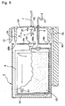
- Fig. 5 is an explanatory view of the present ink cartridge, in which it is shown together with an ink cartridge mounting portion formed in an ink jet printer
- Fig. 6 is a schematic view of an ink supply and discharge system provided in an ink jet printer which uses, as an ink supply source, an ink cartridge with a waste ink absorbing function according to the invention.
- an ink jet printer 1 shown in Fig. 6 is basically similar in structure to an ink jet printer which is generally used and, therefore, the description thereof is omitted here.
- a cartridge mounting portion 3 in which an ink cartridge 2 can be removably mounted.
- an ink supply needle 5 and a waste liquid needle 5 are mounted in such a manner that, for example, they extend horizontally.
- the ink cartridge 2 is slided horizontally with respect to the two needles 4 and 5 to thereby insert the two needles 4 and 5 into their respective given portions (to be discussed later) of the ink cartridge 2, then there is formed an ink flow passage between the ink cartridge 2 and ink jet printer 1.
- ink stored in an ink bag 6 stored in the ink cartridge 2 is taken out into an ink supply tube 7 through the ink supply needle 4.
- a filter 8 which is used to filter dust and foreign substance from the ink.
- the ink is guided to a print head 9 of the ink jet printer 1 by the ink supply tube 7.
- the print head 9 is held by a carriage (not shown) and can be moved reciprocatingly in the longitudinal direction thereof along the surface of a platen 11.
- a recording sheet (not shown) is fed along the surface of the platen 11 in a direction at right angles to the moving direction of the print head 9, and printing is executed on the recording sheet by the print head 9.
- a head cap 12 is disposed at a position out of the moving range of the print head 9 for printing, while the print head 9 is moved periodically up to the position of the head cap 12.
- a waste liquid tube 13 which is used to collect from the head cap 12 the waste ink that has been collected or sucked from the print head 9.
- a waste liquid pump 14 which serves as a drive source for collecting the waste ink.
- waste ink which has been collected by the waste liquid pump 14 through the waste liquid tube 13, is absorbed through the waste liquid needle 5 by a waste ink absorbing member (to be discussed later) stored in the ink cartridge 2 and is thereby collected here.
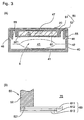
- Fig. 1 is an exploded perspective view of the ink cartridge 2
- Fig. 2 is a front view of the ink cartridge 2, when it is viewed from the ink take-out port side thereof
- Fig. 3 is a schematic section view of the ink cartridge 2
- Fig. 4 is a partially sectional view of the ink take-out port portion of the ink cartridge 2.
- the ink cartridge 2 comprises an ink bag 6 which stores ink therein, a waste ink absorbing member 20 for absorbing waste ink, and a cartridge case 30 in which the ink bag 6 and waste ink absorbing member 20 are stored.
- the cartridge case 30 comprises a case main body 40 (a first case section) and a cover 50 (a second case section) which are combined together to thereby define two storage portions in which the ink bag 6 and waste ink absorbing member 20 are respectively to be stored.
- the case main body 40 includes a rectangular-shaped case bottom plate portion 41 and a case outer frame portion 42 standing up at right angles from the peripheral edge of the case bottom plate portion 41.
- the case bottom plate portion 41 and case outer frame portion 42 cooperate together in defining a rectangular-shaped recess 43, while the ink bag 6 is stored in the recess 43.
- the cover 50 includes a rectangular-shaped case cover portion 51 having the same size as the case main body 40, and a case inner frame portion 52 which stands up at a position inside the peripheral edge of the case cover portion 51 at right angles to the peripheral edge of the case cover portion 51.
- the case inner frame portion 52 is set in a size which allows the case inner frame portion 52 to be inserted inside the case outer frame portion 42, and the width of the case inner frame portion 52 is set greatly smaller than the width of the case outer frame portion 42.
- the case cover portion 51 and case inner frame portion 52 of the cover 50 cooperate together in forming a rectangular-shaped recess 53 and, in the recess 53, there is stored the waste ink absorbing member 20 having a size and a thickness which allows the waste ink absorbing member to be just fitted into the recess 53, while the opening of the recess 53 is closed by a rectangular-shaped plastic film 60. That is, the recess 53 and plastic film 60 cooperate together in forming a division room 70 (see Fig. 3) for storing a waste ink absorbing member 60.
- the ink bag 6 is formed of flexible material; in particular, for the purpose of enhancing its gas barrier property, the ink bag 6 is composed of an aluminum laminated film in which an aluminum foil is sandwiched by two films, for example, the outside of the aluminum foil is held by a nylon film, while the inside thereof is held by a polyethylene film.
- two sheets of aluminum laminated films are superimposed on top of each other and they are then connected together by thermal welding or by other similar means to thereby produce the main body portion 61 of the ink bag 6.
- the portion of the mutually connected portion of the two aluminum laminated films which is shown by oblique lines in Fig. 1, in more particular, in the ink bag front edge portion, there is mounted by thermal welding or by other similar means an ink take-out port 62 which guides the ink within the ink bag 6 to the outside.
- the ink take-out port 62 can be composed of a plastic molding or the like.
- a fixing groove 621 which is used to fix the ink bag 6 to a given position with respect to the case main body 40 of the cartridge case 30.
- the fixing groove 621 is formed on the outer peripheral surface of the ink take-out port 62 in an annular shape, while it can be fitted with and held by a fitting portion 42a which is formed in the case main body 40.
- the ink take-out port 62 includes a pipe portion 622 for guiding the ink within the ink bag 6 therefrom, and a take-out port rubber 624 formed of elastic material such as rubber or the like which is fitted into a large-diameter opening 623 formed in the leading end portion of the pipe portion 622, while the ink is sealed by the take-out port rubber 624.
- the pipe portion 622 and take-out port rubber 624 there is interposed a thin film portion 625 which prevents the ink from touching the take-out port rubber 624 directly; that is, due to the thin film portion 625, there is eliminated the possibility that the ink can touch the take-out port rubber 624 directly to denature the same to thereby elute and separate impurities therefrom, resulting in the poor printing of the print head 9.
- the rear end portion of the ink bag 6 is fixed to the case main body 40 side by double-side adhesive tape (not shown) or the like.
- a detect plate 63 is fixed to the ink bag 6 by fixing means (not shown) such as double-side adhesive tape or the like.
- the detect tape 63 is used to detect that the amount of the ink left within the ink bag 6 has been reduced down to a previously set amount.
- the detect plate 63 includes a detecting projection 631 which can project externally out of an opening 411 formed in the bottom portion 41 of the case main body 40 as the ink residual amount reduces: that is, if the projecting amount of the detecting projection 631 reaches or exceeds a given amount, then the detecting projection 631 is detected by an ink end detect mechanism (not shown), thereby being able to judge that the ink has run out.
- the cover 50 includes, at the outside positions of the inner frame portion 52 of the case cover portion 51, a pair of securing pawls 54 formed on the front end edge side thereof and extending at right angles to the inner frame portion 52, and a pair of securing pawls 55 formed on the two sides of the rear end portion thereof and similarly extending at right angles to the inner frame portion 52.
- the case main body 40 includes a pair of securing holes 45 into which the securing pawls 54 of the cover 50 can be snap fitted from inside, and a pair of securing grooves 46 into which the securing pawls 55 of the cover 50 can also be snap fitted from inside. Therefore, to mount the cover 50 onto the case main body 40, at first, the securing pawls 54 may be fitted into the securing holes 45 respectively and, next, the securing pawls 55 may be fitted into the securing grooves 46 respectively.
- cover 50 To remove the cover 50 from the case main body 40, after a jig is inserted into a notch 47 formed in the central portion of the rear end wall of the outer case frame portion 42 of the case main body 40, if the cover 50 is forced open using the jig, then the cover 50 can be removed simply.
- a label 56 with instructions and the like printed thereon may be bonded to the surface of the case cover portion 51 of the cover 50, so that the notch 47 can be covered by the label 56.
- the case main body and cover which cooperate together in forming the present ink cartridge, are removably connected together by snap fit. Therefore, when recycling the ink cartridge, the cover can be removed simply, which in turn can facilitate the replacement of the ink bag and waste ink absorbing member.
- the front end wall 48 of the case outer frame portion 42 of the case main body 40 besides the above-mentioned securing holes 45 and fitting portions 42a, there are formed an insertion hole 48a into which the waste liquid needle 5 can be inserted, and two guide holes 48b and 48c into which positioning guide shafts can be inserted respectively when mounting the ink cartridge 2 into the cartridge mounting portion 3 of the ink jet printer 1. Also, at the position of the front end wall 521 of the inner frame portion 52 of the cover 50 that corresponds to the guide hole 48a of the case main body 40, there is provided a take-in port rubber 522 into which the waste needle 5 can be inserted.
- the plastic film 60 defining the division room 70 for storing the waste ink absorbing member 20.
- the four peripheral edge portions of the plastic film 60 are connected by thermal welding to the opening end face 521 of the inner frame portion 52 of the cover 50 in such a manner that they are kept airtight to the end face 521.
- the plastic film 60 is a film of a three-layer structure, while the first film layer 611 thereof is formed of the same plastic material as the cover 50 to which the plastic film 60 is to be thermally welded.
- the material of the cover 50 there is used polystyrene having permeability (vapor permeability) in order to enhance the ink absorbing property of the ink absorbing material or plastic film 60.
- the reason for this is as follows: that is, since water occupies 70 to 80% of the ink in volume, if the water can be discharged outside, then the plastic film 60 is able to absorb the waste ink in a larger amount corresponding to the water discharged. Therefore, the first film 611 is formed of polystyrene film layer.
- a second film layer 612 of the plastic film 60 which is piled up on the surface of the first film layer 611, is a film formed of rubber-system material which is highly resistant to shocks; as the material of the second film layer 612, for example, there is used "Ebar" (trade name).
- the second film layer 612 has similar permeability to polystyrene.
- a third film layer 613 of the plastic film 60 which is piled up on the surface of the second film layer 612, is composed of a PET film, so that the third film layer 613 is higher in permeability than polystyrene.
- the thickness of the first film layer 611 is 40 microns
- the thickness of the second film layer 612 is 15 microns
- the thickness of the third film layer 613 is 12 microns.
- the three layers are to be bonded and fixed to one another with adhesives.
- the division room 70 for storing the waste ink absorbing member 20 is defined by the cover 50 of the ink cartridge and the plastic film 60 thermally welded to the opening of the recess 53 formed in the back surface of the cover 50. Thanks to this, when compared with the conventional ink cartridge in which the division room for storing the waste ink absorbing member 20 is defined by the thick plastic plates, the present ink cartridge can be reduced in size and weight by an amount corresponding to use of the plastic film instead of the plastic plates.
- the division room 70 for storing the waste ink absorbing member 20 can be surely closed in an airtight manner, thereby eliminating the possibility that the collected waste ink can leak outside from the connected surface between the plastic film 60 and cover 50.
- the present ink cartridge 2 when welding the plastic film thermally, for example, by inserting an elastic body such as rubber or the like between a heater and plastic film, the plastic film can be surely contacted with the thermally welded surface which is uneven and thus poor in flatness, so that it is difficult for poor thermal welding to occur. That is, it can be said that the present ink cartridge 2 is advantageous over the conventional ink cartridge in this respect as well.
- the waste ink absorbing member with the waste ink absorbed therein can be replaced. Due to this, the ink cartridge can be recycled simply and also, since the recycling of the ink cartridge can be achieved simply by replacing only the old plastic film with a new one, the present ink cartridge is also economical.
- the surface of the plastic film on the side thereof to be thermally welded is formed of the same plastic material as the cover with which the plastic film is to be thermally welded. This makes it possible to enhance the connecting force that is obtained by means of the above thermal welding. Also, not only because the plastic film has permeability but also because the intermediate or second film layer of the plastic film is formed of the highly shock-resisting material, the shock resistance of the plastic film itself can also be improved. This is another advantage that can be provided by the present ink cartridge.
- the melting point of the first film layer on the side of the present plastic film to be thermally welded is in the range of 110 - 120°C
- the melting point of the third film layer (PET) on the side thereof to be contacted with the heater when thermally welded is 254°C. That is, since the melting point of the heater side film layer is set higher than that of the opposite side in this manner, it is possible to prevent the heater side film layer from melting and sticking to the heater in the thermally welding operation, which results in the improved efficiency of the thermally welding operation.
- the waste ink absorbing member 20 absorbs the ink, it swells; that is, the volume of the waste ink absorbing member 20 increases.
- the increase in the volume of the waste ink absorbing member 20 can be absorbed by the slackening of the plastic film.
- the plastic film is mounted in a slackened manner, then such increase in the volume of the waste ink absorbing member 20 can be absorbed positively.
- the division room is partitioned by the plastic plates, it is not necessary that the division room has been previously formed rather large in expectation of an increase in the volume of the waste ink absorbing member, so that the ink cartridge can be made more compact by an amount corresponding to the reduced size of the division room.
- the waste ink absorbing member when a division room for a waste ink absorbing member is partitioned by a plastic film, the waste ink absorbing member has a large ink (liquid) absorbing capacity, while it swells to a great extent when it absorbs the ink.
- a waste ink absorbing member a liquid-absorbing macromolecular polymer (a super-absorber) which is used in a paper diaper or the like. That is, when a division room for a waste ink absorbing member is partitioned by a plastic plate, although a macromolecular polymer is able to absorb ink, it is not allowed to swell, so that the actual ink absorption thereof is limited.
- a plastic film due to the slackening of the plastic film, the ink absorbing performance of a macromolecular polymer can be displayed to the full.
- the division room 70 which is formed on the back surface of the cover 50 of the ink cartridge 2 and also in which the waste ink absorbing member 20 is stored in a sealed manner, is a hermetically sealed space.
- the hermetically sealed space if air cannot be exhausted from the hermetically sealed space, then there is a possibility that the ink absorbing performance of the waste ink absorbing member 20 can be lowered.
- the present embodiment as can be seen from Fig.
- a plastic film which can be applied to the invention may be composed of a single film layer, instead of the above-mentioned three-layer structure.
- the plastic film is formed of the same plastic material as the cartridge case, then the connecting force due to thermal welding can be improved.
- the plastic film when the plastic film is connected by other means than thermal welding, the plastic film may also be formed of other kind of material.
- a plastic film may also be composed of two film layers.
- a first film layer which is formed of the same plastic material as the cartridge case, while a second film layer disposed on the opposite side to the first film layer may be formed of plastic material which is highly resistant to shocks.
- both of the two film layers may have permeability.
- a plastic film applicable to the invention can also be composed of four or more film layers.
- the plastic film is so formed as to be transparent, there can be provided an advantage that the sealed condition thereof can be checked by observing the thermally welded surface of the plastic film visually after it is thermally welded.
- the ink cartridge mounting portion 3 of the ink jet printer 1 there are formed upper and lower guide portions 31 and 32 which are used not only to guide the insertion of the ink cartridge 2 but also to hold the ink cartridge 2 at a given position.
- an end wall 33 which connects the upper and lower guide portions 31 and 32 to each other.
- two guide shafts 34, 35 there are disposed two guide shafts 34, 35, a base member 36 which is used to fix the ink support needle 4 formed of metal, the waste liquid needle 5, and two walls 37 which are used to position the insertion direction of the ink cartridge 2.
- the guide portions 31, 32, end wall 33, guide shafts 34, 35, waste liquid needle 5, and walls 37 are molded of resin in such a manner that they form an integrally united body.
- the ink supply needle 4 is connected to the ink supply tube 7, whereas the waste liquid needle 5 is connected to the waste liquid tube 13.
- the ink cartridge 2 is guided by the two guide portions 31 and 32 and is inserted in the direction of an arrow D. If the ink cartridge 2 is inserted further from the position thereof shown in Fig. 5, then the guide shaft 34 projecting from the end wall 33 is engaged with a guide hole 48b formed in the ink cartridge 2 and, at the same time, the guide shaft 35 projecting from the end wall 33 is engaged with a guide hole 48c formed in the ink cartridge 2, whereby the upper and lower as well as right and left positions of the ink cartridge 2 are decided.
- the respective leading ends of the guide shafts 34 and 35 are tapered to thereby facilitate the smooth insertion of the guide shafts 34 and 35 into their respective guide holes 48b and 48c.
- the ink supply needle 4 passes through the take-out port rubber 624 and reaches the ink stored within the ink bag 6. Almost at the same time, the waste liquid needle 5 passes through the take-in port rubber 522 and is inserted into the waste ink absorbing member 20 disposed within the ink cartridge 2.
- the front surface 48 thereof is finally contacted with the walls 37 which are formed in the periphery of the base member 36, so that the ink cartridge 2 is fixed at this position by a lock member (not shown).
- the ink bag 6 disposed within the ink cartridge 2 is allowed to communicate with the print head 9 through the ink supply tube 7, while the waste ink absorbing member 20 is connected to the waste liquid tube 13.
- the take-out port rubber 624 is closely contacted with the side surface of the ink supply needle 4 to thereby prevent the ink from leaking out from the ink bag 6, while the take-in port rubber 522 is closely contacted with the side surface of the waste liquid needle 5 to thereby prevent the waste liquid from leaking externally of the ink cartridge 2 from the waste ink absorbing member 20.
- the locking or fixation of the ink cartridge 2 by the lock member is removed and then the ink cartridge 2 is moved in the opposite direction to the arrow D direction. Due to this, the ink supply needle 4 is removed from the take-out port rubber 624 and the waste liquid needle 5 is removed from the take-in port rubber 522 and, after then, the engagement between the guide shaft 34 and guide hole 48b as well as the engagement between the guide shaft 35 and guide hole 48c are respectively removed, so that the ink cartridge 2 is guided by the two guide shafts 34 and 35 and is thus moved parallel to the ink supply needle 4 and waste liquid needle 5. This parallel movement of the ink cartridge 2 prevents an undesirable force from being applied to the ink supply needle 4 and waste liquid needle 5 in the upper and lower as well as right and left directions.
- the waste liquid needle 5 is a resin needle which is formed integrally with the ink cartridge mounting portion 3 of the ink jet printer 1.
- the waste liquid needle 5 can also be formed of metal.
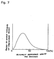
- Fig. 7 shows a frequency distribution curve which is obtained from the results of a test in which dozens of ink cartridges were used and checked for the waste ink absorbing amounts of the waste ink absorbing members of the ink cartridges after they had been used.
- ink bags in each of which ink of the order of 110 cc is stored, and ink cartridges each of which includes an ink absorbing member having a volume of the order of 110 cm 3 .
- the ink cartridges were mounted in a large number of printers, the printers were used with various using frequencies, the cartridges were collected at the time when the ink is used up, and the amounts of waste ink collected by the waste ink absorbing members of the ink cartridges were measured.
- the horizontal axis of a graphical representation shown in Fig. 7 shows ratios of the actually absorbed waste ink amounts of the waste ink absorbing members to the maximum waste ink absorbing amounts of the waste ink absorbing members (that is, the ratios of use of the waste ink absorbing members).
- the horizontal axis shows 0%, then it means that the waste ink is not collected at all; and, if it shows 100%, then it means that the waste ink is collected up to saturation.
- the vertical axis of Fig. 7 shows the frequency of the ink cartridges, which belongs to the use ratios of the waste ink absorbing members thereof, to the whole number of the ink cartridges used in the test.
- no ink cartridge belongs to the use ratio of its waste ink absorbing member of 100% and, in most of the ink cartridges, the waste ink is collected in such a manner that the waste ink absorbing member use ratio becomes 20 - 50%. That is, this shows that, in these waste ink absorbing members, there are still left portions which are capable of absorbing the waste ink further.
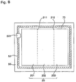
- Figs. 8 and 9 respectively show an embodiment of an ink absorbing member and, in particular, Figs. 8 and 9 are plan views of the ink absorbing member which is mounted in the division room 70.
- Fig. 8 shows a state of the ink absorbing member before it is used
- Fig. 9 shows a state thereof after it is used.
- the present ink absorbing member can be easily divided along the two perforations into three ink absorbing member sections 201, 202 and 203.
- the two perforations are set in such a manner that they are almost parallel to the side surface of the ink absorbing member 20 on the side thereof where the ink take-in port rubber 522 is disposed.
- the two perforations 211 and 212 are formed in such a manner that, when the ink absorbing member 20 is divided, the three absorbing member sections 201, 202 and 203 are almost equal in shape to one another.
- the waste ink is fed through the ink take-in port rubber 522 and is then absorbed by the waste ink absorbing member 20 which is stored within the division room 70. And, each time the ink suction and cleaning are repeatedly executed, the ink is penetrated little by little into the ink absorbing member 20 and the ink is used on and from the absorbing member section 201 side of the ink take-in port rubber 522.
- the ink is repeatedly used in printing, the ink used is cleaned as the need arises, and, when the ink of the ink bag 6 is used up, the waste ink 22 collected is stored in the ink absorbing member, for example, in such a manner as shown in Fig. 9.
- the ink absorbing member 20 may be cut at the perforation 212, the thus cut absorbing member sections 201 and 202 portions thereof may be replaced, whereas the absorbing member section 203 portion of the ink absorbing member 20, which is not contaminated by the waste ink at all, can be used again as it is.
- the ink absorbing member 20 may be cut at the perforation 211, and only the absorbing member section 201 portion thereof may be replaced.
- the use ratio of the waste ink absorbing member falls within the range of 20 - 50% and, therefore, the absorbing member 203 can be scarcely contaminated.
- the ink absorbing member 20 is endowed with an ability to absorb 90% or more of the ink stored within the ink bag 6.
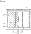
- Fig. 10 shows another embodiment of the ink absorbing member and, in particular, Fig. 10 is a plan view of the ink absorbing member mounted in the division room 70, showing a state thereof after it is used.
- the perforations are formed in the ink absorbing member so as to be able to divide the same easily.
- three previously divided ink absorbing members 207, 208 and 209 are arranged side by side within the division room 70, a similar effect to the previously mentioned embodiment can also be obtained.
- the break 21 is not always limited to the perforation-shaped break but, of course, other type of break such as a break composed of a V-shaped groove or the like can also be used, provided that it allows the ink absorbing member to be divided easily.
- the ink absorbing member is formed in the above-mentioned manner, the quantities of the waste ink absorbing members 20 to be wasted can be reduced, which in turn can reduce the cost necessary to dispose of the waste and also can decrease the ill effects of the waste on the environment. Also, since the quantities of new waste ink absorbing members 20 to be supplied into the ink cartridge in recycling operations can be reduced, the cost of the ink cartridge can be decreased.
Applications Claiming Priority (5)
| Application Number | Priority Date | Filing Date | Title |
|---|---|---|---|
| JP23263797A JP3533897B2 (ja) | 1997-08-28 | 1997-08-28 | 廃インク吸収機能付きインクカートリッジ |
| JP23263797 | 1997-08-28 | ||
| JP29997797A JPH11129488A (ja) | 1997-10-31 | 1997-10-31 | 廃インク吸収機能付きインクカートリッジ |
| JP29997797 | 1997-10-31 | ||
| PCT/JP1998/003829 WO1999011462A1 (en) | 1997-08-28 | 1998-08-28 | Ink cartridge having waste ink absorbing function |
Publications (3)
| Publication Number | Publication Date |
|---|---|
| EP0928694A1 true EP0928694A1 (de) | 1999-07-14 |
| EP0928694A4 EP0928694A4 (de) | 1999-07-28 |
| EP0928694B1 EP0928694B1 (de) | 2001-07-25 |
Family
ID=26530572
Family Applications (1)
| Application Number | Title | Priority Date | Filing Date |
|---|---|---|---|
| EP98940591A Expired - Lifetime EP0928694B1 (de) | 1997-08-28 | 1998-08-28 | Tintenbehälter mit abfalltintenabsorptionsfunktion |
Country Status (9)
| Country | Link |
|---|---|
| US (1) | US6281911B1 (de) |
| EP (1) | EP0928694B1 (de) |
| KR (2) | KR100361484B1 (de) |
| CN (1) | CN1135169C (de) |
| AU (1) | AU727666B2 (de) |
| CA (1) | CA2270169C (de) |
| DE (1) | DE69801207T2 (de) |
| HK (1) | HK1021350A1 (de) |
| WO (1) | WO1999011462A1 (de) |
Cited By (12)
| Publication number | Priority date | Publication date | Assignee | Title |
|---|---|---|---|---|
| DE19915330A1 (de) * | 1999-04-03 | 2000-10-12 | Tally Computerdrucker Gmbh | Tintendrucker mit einem auswechselbaren Auffanggefäß |
| EP1120258A2 (de) * | 2000-01-21 | 2001-08-01 | Seiko Epson Corporation | Tintenpatrone und Tintenstrahldruckvorrichtung mit einer derartigen Tintenpatrone |
| EP1122073A3 (de) * | 2000-01-31 | 2002-03-20 | Seiko Epson Corporation | Tintenpatrone und Tintenstrahldrucker |
| EP1416335A1 (de) * | 2002-10-31 | 2004-05-06 | Samsung Electronics Co., Ltd. | Einrichtung zur Entsorgung von Tinte für ein electrophotografisches Gerät, welches Flüssigtoner verwendet |
| WO2004096558A1 (en) * | 2003-04-25 | 2004-11-11 | Canon Kabushiki Kaisha | Ink cartridge, recording apparatus employing ink cartridge, and manufacturing method for ink cartridge |
| EP1880855A1 (de) * | 2006-07-19 | 2008-01-23 | Ricoh Company, Ltd. | Behälter zur Lagerung von Flüssigabfall, Flüssigabfallablaufvorrichtung und Bilderzeugungsvorrichtung |
| EP2105308A1 (de) * | 2000-01-21 | 2009-09-30 | Seiko Epson Corporation | Tintenpatrone für Aufzeichnungsgerät und Tintenstrahlaufzeichnungsgerät |
| EP2246193A1 (de) * | 2008-02-29 | 2010-11-03 | Seiko Epson Corporation | Element zur wiederherstellung einer abfallflüssigkeit |
| EP2261038A1 (de) * | 2008-02-29 | 2010-12-15 | Seiko Epson Corporation | Verfahren zur wiederverwendung eines behälterteils |
| WO2014049441A1 (en) * | 2012-09-26 | 2014-04-03 | Funai Electric Co., Ltd. | Expandable waste ink receptacle for micro-fluid supply item |
| US9168756B2 (en) | 2008-02-29 | 2015-10-27 | Seiko Epson Corporation | Waste liquid container and waste liquid discharging device |
| CN103991290B (zh) * | 2008-02-29 | 2016-04-20 | 精工爱普生株式会社 | 废液回收体 |
Families Citing this family (43)
| Publication number | Priority date | Publication date | Assignee | Title |
|---|---|---|---|---|
| GB9621061D0 (en) * | 1996-10-09 | 1996-11-27 | Frontline Display Limited | Image display apparatus |
| US7384134B2 (en) * | 1999-05-25 | 2008-06-10 | Silverbrook Research Pty Ltd | Ink cartridge with collapsible ink containers for an inkjet printer |
| US6825945B1 (en) * | 1999-05-25 | 2004-11-30 | Silverbrook Research Pty Ltd | Method and system for delivery of a brochure |
| CN1177694C (zh) * | 2000-01-31 | 2004-12-01 | 精工爱普生株式会社 | 用于喷墨打印机的墨盒 |
| JP3885872B2 (ja) * | 2001-10-09 | 2007-02-28 | ブラザー工業株式会社 | インク収容装置及びそれを備えたインクジェット記録装置 |
| US6840617B2 (en) * | 2002-04-02 | 2005-01-11 | Lexmark International, Inc. | Mid-frame for an imaging apparatus |
| US6722752B2 (en) * | 2002-09-04 | 2004-04-20 | Hewlett-Packard Development Company, L.P. | Pen maintenance system and method for operating same |
| JP3807358B2 (ja) * | 2002-10-22 | 2006-08-09 | セイコーエプソン株式会社 | 液体容器及び液体噴射装置 |
| US7048353B2 (en) | 2002-10-22 | 2006-05-23 | Hewlett-Packard Development Company, L.P. | Printhead maintenance system |
| JP3900117B2 (ja) * | 2002-12-10 | 2007-04-04 | セイコーエプソン株式会社 | 液体カートリッジの製造方法 |
| KR100474493B1 (ko) * | 2002-12-26 | 2005-03-09 | 삼성전자주식회사 | 잉크카트리지 |
| US20040150698A1 (en) * | 2003-01-31 | 2004-08-05 | William Caro | Inkjet pen with removable lid |
| JP2005007830A (ja) * | 2003-06-20 | 2005-01-13 | Brother Ind Ltd | 筐体の通風構造及び筐体の通風構造を備えた印字装置 |
| US7758172B2 (en) | 2003-07-18 | 2010-07-20 | Seiko Epson Corporation | Injection apparatus and a valve device provided in a passage |
| EP1498272A1 (de) * | 2003-07-18 | 2005-01-19 | Seiko Epson Corporation | Flüssigkeitsbehälter |
| CN100564043C (zh) * | 2003-07-18 | 2009-12-02 | 精工爱普生株式会社 | 液体容器 |
| JP2005053212A (ja) * | 2003-07-18 | 2005-03-03 | Seiko Epson Corp | 液体収容体 |
| US7290869B2 (en) * | 2003-07-25 | 2007-11-06 | Seiko Epson Corporation | Liquid container |
| US7665824B2 (en) * | 2003-10-31 | 2010-02-23 | Hewlett-Packard Development Company, L.P. | Printing system condenser |
| US20090273655A1 (en) * | 2004-12-29 | 2009-11-05 | Sj-D5 Inc. | Ink reservoir for inkjet print system |
| JP2006305941A (ja) | 2005-04-28 | 2006-11-09 | Seiko Epson Corp | 液体供給回収装置 |
| JP4848699B2 (ja) * | 2005-08-04 | 2011-12-28 | セイコーエプソン株式会社 | 廃インク貯留構造及びこれを備えたインクカートリッジ並びにインクジェットプリンタ |
| JP4792870B2 (ja) * | 2005-08-15 | 2011-10-12 | セイコーエプソン株式会社 | インクジェット記録装置 |
| JP4854243B2 (ja) * | 2005-09-16 | 2012-01-18 | 株式会社リコー | 廃液収容容器及び画像形成装置 |
| KR20070078205A (ko) * | 2006-01-26 | 2007-07-31 | 삼성전자주식회사 | 잉크젯 프린팅 시스템의 잉크 공급 장치 |
| JP5007601B2 (ja) * | 2007-05-02 | 2012-08-22 | セイコーエプソン株式会社 | 液体収容容器におけるシール方法、液体収容容器の再生方法、液体収容容器 |
| JP5142800B2 (ja) * | 2007-06-04 | 2013-02-13 | キヤノン株式会社 | 廃インク収容部 |
| JP5106134B2 (ja) * | 2008-01-10 | 2012-12-26 | キヤノン株式会社 | 液体収納容器 |
| JP2009202522A (ja) * | 2008-02-29 | 2009-09-10 | Seiko Epson Corp | 廃液回収体及び液体噴射装置 |
| JP5471260B2 (ja) | 2008-11-14 | 2014-04-16 | セイコーエプソン株式会社 | 液体収容容器 |
| US8359167B2 (en) * | 2009-03-23 | 2013-01-22 | Regents Of The University Of California | Measurement of carbon capture efficiency and stored carbon leakage |
| JP5585086B2 (ja) * | 2009-03-24 | 2014-09-10 | セイコーエプソン株式会社 | 液体収容容器 |
| JP5316326B2 (ja) * | 2009-09-04 | 2013-10-16 | 株式会社リコー | 液体収容容器、液体収容容器の組立て方法、液体収容容器の分解方法及び画像形成装置 |
| JP5532820B2 (ja) * | 2009-10-29 | 2014-06-25 | セイコーエプソン株式会社 | 液体容器 |
| JP2011167960A (ja) * | 2010-02-19 | 2011-09-01 | Seiko Epson Corp | 液体噴射装置 |
| US8677978B2 (en) * | 2010-03-03 | 2014-03-25 | Kohler Co. | System and method for carburetor venting |
| KR101248854B1 (ko) * | 2011-01-20 | 2013-04-01 | 전문배 | 잉크팩 내장용 카트리지 |
| JP5906622B2 (ja) | 2011-09-09 | 2016-04-20 | ブラザー工業株式会社 | インクジェット記録装置 |
| JP6020120B2 (ja) * | 2012-12-14 | 2016-11-02 | ブラザー工業株式会社 | インクジェット記録装置 |
| JP6384031B2 (ja) * | 2013-09-04 | 2018-09-05 | セイコーエプソン株式会社 | 液体収容体及び液体噴射システム |
| JP6398274B2 (ja) * | 2014-04-11 | 2018-10-03 | セイコーエプソン株式会社 | 液体容器、アダプター、ならびに液体噴射装置 |
| JP6665649B2 (ja) * | 2016-04-15 | 2020-03-13 | セイコーエプソン株式会社 | カートリッジ |
| US11173716B2 (en) | 2018-06-18 | 2021-11-16 | Hewlett-Packard Development Company, L.P. | Leak mitigation devices |
Citations (2)
| Publication number | Priority date | Publication date | Assignee | Title |
|---|---|---|---|---|
| US5400066A (en) * | 1990-12-10 | 1995-03-21 | Canon Kabushiki Kaisha | Ink tank cartridge that prevents leakage of residual ink and ink jet recording apparatus using same |
| EP0710561A2 (de) * | 1994-11-07 | 1996-05-08 | Canon Aptex Inc. | Drucker mit zugehöriger Tintenkassette |
Family Cites Families (7)
| Publication number | Priority date | Publication date | Assignee | Title |
|---|---|---|---|---|
| JPS6112352A (ja) | 1984-06-29 | 1986-01-20 | Canon Inc | 廃インク容器 |
| JP2586016B2 (ja) | 1986-11-05 | 1997-02-26 | セイコーエプソン株式会社 | インク容器及びインク容器の製造方法 |
| DE68920262T3 (de) * | 1988-10-14 | 2000-11-16 | Seiko Epson Corp | Tintenkassette für einen Tintenstrahldrucker. |
| GB2242867B (en) * | 1990-02-15 | 1994-04-13 | Canon Kk | Waste ink receiving cartridge and ink recording apparatus using said cartridge |
| JPH0516377A (ja) | 1991-07-08 | 1993-01-26 | Seiko Epson Corp | インクカートリツジ |
| JPH05162333A (ja) | 1991-12-13 | 1993-06-29 | Canon Inc | インクタンクカートリッジ |
| JPH06226991A (ja) * | 1993-02-04 | 1994-08-16 | Seiko Epson Corp | インク容器 |
-
1998
- 1998-08-28 AU AU88863/98A patent/AU727666B2/en not_active Ceased
- 1998-08-28 EP EP98940591A patent/EP0928694B1/de not_active Expired - Lifetime
- 1998-08-28 WO PCT/JP1998/003829 patent/WO1999011462A1/ja not_active Application Discontinuation
- 1998-08-28 DE DE69801207T patent/DE69801207T2/de not_active Expired - Lifetime
- 1998-08-28 KR KR1019997003668A patent/KR100361484B1/ko not_active IP Right Cessation
- 1998-08-28 US US09/297,161 patent/US6281911B1/en not_active Expired - Lifetime
- 1998-08-28 KR KR10-2002-7006762A patent/KR100404637B1/ko not_active IP Right Cessation
- 1998-08-28 CN CNB988016117A patent/CN1135169C/zh not_active Expired - Fee Related
- 1998-08-28 CA CA002270169A patent/CA2270169C/en not_active Expired - Fee Related
-
2000
- 2000-01-12 HK HK00100204A patent/HK1021350A1/xx not_active IP Right Cessation
Patent Citations (2)
| Publication number | Priority date | Publication date | Assignee | Title |
|---|---|---|---|---|
| US5400066A (en) * | 1990-12-10 | 1995-03-21 | Canon Kabushiki Kaisha | Ink tank cartridge that prevents leakage of residual ink and ink jet recording apparatus using same |
| EP0710561A2 (de) * | 1994-11-07 | 1996-05-08 | Canon Aptex Inc. | Drucker mit zugehöriger Tintenkassette |
Non-Patent Citations (1)
| Title |
|---|
| See also references of WO9911462A1 * |
Cited By (29)
| Publication number | Priority date | Publication date | Assignee | Title |
|---|---|---|---|---|
| DE19915330B4 (de) * | 1999-04-03 | 2005-03-24 | Tally Computerdrucker Gmbh | Tintendrucker mit einem auswechselbaren Auffanggefäß |
| DE19915330A1 (de) * | 1999-04-03 | 2000-10-12 | Tally Computerdrucker Gmbh | Tintendrucker mit einem auswechselbaren Auffanggefäß |
| US7784923B2 (en) | 1999-10-08 | 2010-08-31 | Seiko Epson Corporation | Ink cartridge, and ink-jet recording apparatus using the same |
| US6582068B2 (en) | 2000-01-21 | 2003-06-24 | Seiko Epson Corporation | Ink cartridge, and ink-jet recording apparatus using the same |
| US8636347B2 (en) | 2000-01-21 | 2014-01-28 | Seiko Epson Corporation | Ink cartridge, and ink-jet recording apparatus using the same |
| US8998394B2 (en) | 2000-01-21 | 2015-04-07 | Seiko Epson Corporation | Ink cartridge, and ink-jet recording apparatus using the same |
| US6758556B2 (en) | 2000-01-21 | 2004-07-06 | Seiko Epson Corporation | Ink cartridge, and ink-jet recording apparatus using the same |
| EP1120258A2 (de) * | 2000-01-21 | 2001-08-01 | Seiko Epson Corporation | Tintenpatrone und Tintenstrahldruckvorrichtung mit einer derartigen Tintenpatrone |
| EP2105308A1 (de) * | 2000-01-21 | 2009-09-30 | Seiko Epson Corporation | Tintenpatrone für Aufzeichnungsgerät und Tintenstrahlaufzeichnungsgerät |
| EP1120258A3 (de) * | 2000-01-21 | 2001-11-28 | Seiko Epson Corporation | Tintenpatrone und Tintenstrahldruckvorrichtung mit einer derartigen Tintenpatrone |
| US7152965B2 (en) | 2000-01-21 | 2006-12-26 | Seiko Epson Corporation | Ink cartridge, and ink-jet recording apparatus using the same |
| EP1122073A3 (de) * | 2000-01-31 | 2002-03-20 | Seiko Epson Corporation | Tintenpatrone und Tintenstrahldrucker |
| US6908182B2 (en) | 2000-01-31 | 2005-06-21 | Seiko Epson Corporation | Ink cartridge and ink jet printer |
| US7197266B2 (en) | 2002-10-31 | 2007-03-27 | Samsung Electronics Co, Ltd | Ink disposal in cartridges |
| US6999702B2 (en) | 2002-10-31 | 2006-02-14 | Samsung Electronics Co., Ltd. | Ink disposal in cartridges |
| US6907213B2 (en) | 2002-10-31 | 2005-06-14 | Samsung Electronics Co., Ltd. | Ink disposal in cartridges |
| EP1416335A1 (de) * | 2002-10-31 | 2004-05-06 | Samsung Electronics Co., Ltd. | Einrichtung zur Entsorgung von Tinte für ein electrophotografisches Gerät, welches Flüssigtoner verwendet |
| US7431438B2 (en) * | 2003-04-25 | 2008-10-07 | Canon Kabushiki Kaisha | Ink cartridge, recording apparatus employing ink cartridge, and manufacturing method for ink cartridge |
| WO2004096558A1 (en) * | 2003-04-25 | 2004-11-11 | Canon Kabushiki Kaisha | Ink cartridge, recording apparatus employing ink cartridge, and manufacturing method for ink cartridge |
| EP1880855A1 (de) * | 2006-07-19 | 2008-01-23 | Ricoh Company, Ltd. | Behälter zur Lagerung von Flüssigabfall, Flüssigabfallablaufvorrichtung und Bilderzeugungsvorrichtung |
| US8096636B2 (en) | 2006-07-19 | 2012-01-17 | Ricoh Company, Ltd. | Waste liquid storage container, waste liquid discharge device, and image formation apparatus |
| EP2246193A4 (de) * | 2008-02-29 | 2011-02-23 | Seiko Epson Corp | Element zur wiederherstellung einer abfallflüssigkeit |
| EP2261038A4 (de) * | 2008-02-29 | 2011-02-23 | Seiko Epson Corp | Verfahren zur wiederverwendung eines behälterteils |
| US8353585B2 (en) | 2008-02-29 | 2013-01-15 | Seiko Epson Corporation | Waste liquid collector |
| EP2261038A1 (de) * | 2008-02-29 | 2010-12-15 | Seiko Epson Corporation | Verfahren zur wiederverwendung eines behälterteils |
| EP2246193A1 (de) * | 2008-02-29 | 2010-11-03 | Seiko Epson Corporation | Element zur wiederherstellung einer abfallflüssigkeit |
| US9168756B2 (en) | 2008-02-29 | 2015-10-27 | Seiko Epson Corporation | Waste liquid container and waste liquid discharging device |
| CN103991290B (zh) * | 2008-02-29 | 2016-04-20 | 精工爱普生株式会社 | 废液回收体 |
| WO2014049441A1 (en) * | 2012-09-26 | 2014-04-03 | Funai Electric Co., Ltd. | Expandable waste ink receptacle for micro-fluid supply item |
Also Published As
| Publication number | Publication date |
|---|---|
| WO1999011462A1 (en) | 1999-03-11 |
| DE69801207T2 (de) | 2002-04-18 |
| EP0928694B1 (de) | 2001-07-25 |
| AU8886398A (en) | 1999-03-22 |
| KR20020067528A (ko) | 2002-08-22 |
| CA2270169C (en) | 2007-04-17 |
| AU727666B2 (en) | 2000-12-21 |
| KR100404637B1 (ko) | 2003-11-07 |
| CN1242741A (zh) | 2000-01-26 |
| CA2270169A1 (en) | 1999-03-11 |
| EP0928694A4 (de) | 1999-07-28 |
| DE69801207D1 (de) | 2001-08-30 |
| KR20000068844A (ko) | 2000-11-25 |
| KR100361484B1 (ko) | 2002-11-21 |
| US6281911B1 (en) | 2001-08-28 |
| HK1021350A1 (en) | 2000-06-09 |
| CN1135169C (zh) | 2004-01-21 |
Similar Documents
| Publication | Publication Date | Title |
|---|---|---|
| EP0928694B1 (de) | Tintenbehälter mit abfalltintenabsorptionsfunktion | |
| US6053607A (en) | Negative pressure ink delivery system | |
| US5971533A (en) | Ink cartridge and printer | |
| JP4848699B2 (ja) | 廃インク貯留構造及びこれを備えたインクカートリッジ並びにインクジェットプリンタ | |
| US7121657B2 (en) | Ink cartridge for inkjet recording apparatus | |
| US9248657B2 (en) | Fluid storage container | |
| US20010024226A1 (en) | Ink cartridge and remaining ink volume detection method | |
| JP3533897B2 (ja) | 廃インク吸収機能付きインクカートリッジ | |
| US20080225093A1 (en) | Liquid storage container and refilling method using the same | |
| US20100085398A1 (en) | Ink surface detecting systems and ink cartridge | |
| JPH11157099A (ja) | インクカートリッジ | |
| JP6852317B2 (ja) | 液体回収装置、及びこれを備えた液体消費装置 | |
| JPH11157097A (ja) | インクカートリッジ及びそれを装着可能なインクジェット記録装置、その記録装置の制御方法 | |
| JP4404099B2 (ja) | インクカートリッジ及びそれを装着可能なインクジェット記録装置、その記録装置の制御方法 | |
| JP4998627B2 (ja) | 廃インク貯留構造及びこれを備えたインクカートリッジ並びにインクジェットプリンタ | |
| JP5003830B2 (ja) | 廃インク貯留構造及びこれを備えたインクカートリッジ並びにインクジェットプリンタ | |
| US20240042766A1 (en) | Ink supply device and image forming system | |
| JP2001347687A (ja) | インクカートリッジおよびインクジェットプリンタ | |
| JP5086553B2 (ja) | 液体収容容器 | |
| JP2024006594A (ja) | 液体収容体 | |
| JPH0768772A (ja) | インクジェット用カートリッジ及びインクジェットヘッドとプリンタ |
Legal Events
| Date | Code | Title | Description |
|---|---|---|---|
| PUAI | Public reference made under article 153(3) epc to a published international application that has entered the european phase |
Free format text: ORIGINAL CODE: 0009012 |
|
| 17P | Request for examination filed |
Effective date: 19990427 |
|
| AK | Designated contracting states |
Kind code of ref document: A1 Designated state(s): CH DE FR GB IT LI NL |
|
| A4 | Supplementary search report drawn up and despatched |
Effective date: 19990616 |
|
| AK | Designated contracting states |
Kind code of ref document: A4 Designated state(s): CH DE FR GB IT LI NL |
|
| GRAG | Despatch of communication of intention to grant |
Free format text: ORIGINAL CODE: EPIDOS AGRA |
|
| 17Q | First examination report despatched |
Effective date: 20001012 |
|
| GRAG | Despatch of communication of intention to grant |
Free format text: ORIGINAL CODE: EPIDOS AGRA |
|
| GRAH | Despatch of communication of intention to grant a patent |
Free format text: ORIGINAL CODE: EPIDOS IGRA |
|
| GRAH | Despatch of communication of intention to grant a patent |
Free format text: ORIGINAL CODE: EPIDOS IGRA |
|
| GRAA | (expected) grant |
Free format text: ORIGINAL CODE: 0009210 |
|
| AK | Designated contracting states |
Kind code of ref document: B1 Designated state(s): CH DE FR GB IT LI NL |
|
| ITF | It: translation for a ep patent filed |
Owner name: BUZZI, NOTARO&ANTONIELLI D'OULX |
|
| REG | Reference to a national code |
Ref country code: CH Ref legal event code: EP |
|
| REF | Corresponds to: |
Ref document number: 69801207 Country of ref document: DE Date of ref document: 20010830 |
|
| REG | Reference to a national code |
Ref country code: CH Ref legal event code: NV Representative=s name: BOVARD AG PATENTANWAELTE |
|
| NLR4 | Nl: receipt of corrected translation in the netherlands language at the initiative of the proprietor of the patent | ||
| ET | Fr: translation filed | ||
| REG | Reference to a national code |
Ref country code: GB Ref legal event code: IF02 |
|
| PLBE | No opposition filed within time limit |
Free format text: ORIGINAL CODE: 0009261 |
|
| STAA | Information on the status of an ep patent application or granted ep patent |
Free format text: STATUS: NO OPPOSITION FILED WITHIN TIME LIMIT |
|
| 26N | No opposition filed | ||
| REG | Reference to a national code |
Ref country code: FR Ref legal event code: CL |
|
| REG | Reference to a national code |
Ref country code: CH Ref legal event code: PFA Owner name: SEIKO EPSON CORPORATION Free format text: SEIKO EPSON CORPORATION#4-1, NISHISHINJUKU 2-CHOME#SHINJUKU-KU, TOKYO 163-0811 (JP) -TRANSFER TO- SEIKO EPSON CORPORATION#4-1, NISHISHINJUKU 2-CHOME#SHINJUKU-KU, TOKYO 163-0811 (JP) |
|
| PGFP | Annual fee paid to national office [announced via postgrant information from national office to epo] |
Ref country code: IT Payment date: 20130819 Year of fee payment: 16 |
|
| PG25 | Lapsed in a contracting state [announced via postgrant information from national office to epo] |
Ref country code: IT Free format text: LAPSE BECAUSE OF NON-PAYMENT OF DUE FEES Effective date: 20140828 |
|
| REG | Reference to a national code |
Ref country code: FR Ref legal event code: PLFP Year of fee payment: 19 |
|
| PGFP | Annual fee paid to national office [announced via postgrant information from national office to epo] |
Ref country code: NL Payment date: 20160711 Year of fee payment: 19 |
|
| PGFP | Annual fee paid to national office [announced via postgrant information from national office to epo] |
Ref country code: GB Payment date: 20160824 Year of fee payment: 19 Ref country code: CH Payment date: 20160812 Year of fee payment: 19 Ref country code: DE Payment date: 20160823 Year of fee payment: 19 |
|
| PGFP | Annual fee paid to national office [announced via postgrant information from national office to epo] |
Ref country code: FR Payment date: 20160712 Year of fee payment: 19 |
|
| REG | Reference to a national code |
Ref country code: DE Ref legal event code: R119 Ref document number: 69801207 Country of ref document: DE |
|
| REG | Reference to a national code |
Ref country code: CH Ref legal event code: PL |
|
| REG | Reference to a national code |
Ref country code: NL Ref legal event code: MM Effective date: 20170901 |
|
| GBPC | Gb: european patent ceased through non-payment of renewal fee |
Effective date: 20170828 |
|
| PG25 | Lapsed in a contracting state [announced via postgrant information from national office to epo] |
Ref country code: LI Free format text: LAPSE BECAUSE OF NON-PAYMENT OF DUE FEES Effective date: 20170831 Ref country code: CH Free format text: LAPSE BECAUSE OF NON-PAYMENT OF DUE FEES Effective date: 20170831 |
|
| REG | Reference to a national code |
Ref country code: FR Ref legal event code: ST Effective date: 20180430 |
|
| PG25 | Lapsed in a contracting state [announced via postgrant information from national office to epo] |
Ref country code: NL Free format text: LAPSE BECAUSE OF NON-PAYMENT OF DUE FEES Effective date: 20170901 |
|
| PG25 | Lapsed in a contracting state [announced via postgrant information from national office to epo] |
Ref country code: DE Free format text: LAPSE BECAUSE OF NON-PAYMENT OF DUE FEES Effective date: 20180301 Ref country code: GB Free format text: LAPSE BECAUSE OF NON-PAYMENT OF DUE FEES Effective date: 20170828 |
|
| PG25 | Lapsed in a contracting state [announced via postgrant information from national office to epo] |
Ref country code: FR Free format text: LAPSE BECAUSE OF NON-PAYMENT OF DUE FEES Effective date: 20170831 |