EP0922666B1 - Reformierungsvorrichtung zum Erzeugen eines Spaltgases mit verringertem CO-Gehalt. - Google Patents
Reformierungsvorrichtung zum Erzeugen eines Spaltgases mit verringertem CO-Gehalt. Download PDFInfo
- Publication number
- EP0922666B1 EP0922666B1 EP97928525A EP97928525A EP0922666B1 EP 0922666 B1 EP0922666 B1 EP 0922666B1 EP 97928525 A EP97928525 A EP 97928525A EP 97928525 A EP97928525 A EP 97928525A EP 0922666 B1 EP0922666 B1 EP 0922666B1
- Authority
- EP
- European Patent Office
- Prior art keywords
- reforming
- unit
- reaction unit
- raw material
- shift reaction
- Prior art date
- Legal status (The legal status is an assumption and is not a legal conclusion. Google has not performed a legal analysis and makes no representation as to the accuracy of the status listed.)
- Expired - Lifetime
Links
Images


Classifications
-
- H—ELECTRICITY
- H01—ELECTRIC ELEMENTS
- H01M—PROCESSES OR MEANS, e.g. BATTERIES, FOR THE DIRECT CONVERSION OF CHEMICAL ENERGY INTO ELECTRICAL ENERGY
- H01M8/00—Fuel cells; Manufacture thereof
- H01M8/06—Combination of fuel cells with means for production of reactants or for treatment of residues
- H01M8/0606—Combination of fuel cells with means for production of reactants or for treatment of residues with means for production of gaseous reactants
- H01M8/0612—Combination of fuel cells with means for production of reactants or for treatment of residues with means for production of gaseous reactants from carbon-containing material
- H01M8/0625—Combination of fuel cells with means for production of reactants or for treatment of residues with means for production of gaseous reactants from carbon-containing material in a modular combined reactor/fuel cell structure
- H01M8/0631—Reactor construction specially adapted for combination reactor/fuel cell
-
- B—PERFORMING OPERATIONS; TRANSPORTING
- B01—PHYSICAL OR CHEMICAL PROCESSES OR APPARATUS IN GENERAL
- B01J—CHEMICAL OR PHYSICAL PROCESSES, e.g. CATALYSIS OR COLLOID CHEMISTRY; THEIR RELEVANT APPARATUS
- B01J8/00—Chemical or physical processes in general, conducted in the presence of fluids and solid particles; Apparatus for such processes
- B01J8/02—Chemical or physical processes in general, conducted in the presence of fluids and solid particles; Apparatus for such processes with stationary particles, e.g. in fixed beds
- B01J8/04—Chemical or physical processes in general, conducted in the presence of fluids and solid particles; Apparatus for such processes with stationary particles, e.g. in fixed beds the fluid passing successively through two or more beds
- B01J8/0446—Chemical or physical processes in general, conducted in the presence of fluids and solid particles; Apparatus for such processes with stationary particles, e.g. in fixed beds the fluid passing successively through two or more beds the flow within the beds being predominantly vertical
- B01J8/0461—Chemical or physical processes in general, conducted in the presence of fluids and solid particles; Apparatus for such processes with stationary particles, e.g. in fixed beds the fluid passing successively through two or more beds the flow within the beds being predominantly vertical in two or more cylindrical annular shaped beds
- B01J8/0465—Chemical or physical processes in general, conducted in the presence of fluids and solid particles; Apparatus for such processes with stationary particles, e.g. in fixed beds the fluid passing successively through two or more beds the flow within the beds being predominantly vertical in two or more cylindrical annular shaped beds the beds being concentric
-
- B—PERFORMING OPERATIONS; TRANSPORTING
- B01—PHYSICAL OR CHEMICAL PROCESSES OR APPARATUS IN GENERAL
- B01J—CHEMICAL OR PHYSICAL PROCESSES, e.g. CATALYSIS OR COLLOID CHEMISTRY; THEIR RELEVANT APPARATUS
- B01J8/00—Chemical or physical processes in general, conducted in the presence of fluids and solid particles; Apparatus for such processes
- B01J8/02—Chemical or physical processes in general, conducted in the presence of fluids and solid particles; Apparatus for such processes with stationary particles, e.g. in fixed beds
- B01J8/04—Chemical or physical processes in general, conducted in the presence of fluids and solid particles; Apparatus for such processes with stationary particles, e.g. in fixed beds the fluid passing successively through two or more beds
- B01J8/0446—Chemical or physical processes in general, conducted in the presence of fluids and solid particles; Apparatus for such processes with stationary particles, e.g. in fixed beds the fluid passing successively through two or more beds the flow within the beds being predominantly vertical
- B01J8/0476—Chemical or physical processes in general, conducted in the presence of fluids and solid particles; Apparatus for such processes with stationary particles, e.g. in fixed beds the fluid passing successively through two or more beds the flow within the beds being predominantly vertical in two or more otherwise shaped beds
-
- B—PERFORMING OPERATIONS; TRANSPORTING
- B01—PHYSICAL OR CHEMICAL PROCESSES OR APPARATUS IN GENERAL
- B01J—CHEMICAL OR PHYSICAL PROCESSES, e.g. CATALYSIS OR COLLOID CHEMISTRY; THEIR RELEVANT APPARATUS
- B01J8/00—Chemical or physical processes in general, conducted in the presence of fluids and solid particles; Apparatus for such processes
- B01J8/02—Chemical or physical processes in general, conducted in the presence of fluids and solid particles; Apparatus for such processes with stationary particles, e.g. in fixed beds
- B01J8/04—Chemical or physical processes in general, conducted in the presence of fluids and solid particles; Apparatus for such processes with stationary particles, e.g. in fixed beds the fluid passing successively through two or more beds
- B01J8/0496—Heating or cooling the reactor
-
- C—CHEMISTRY; METALLURGY
- C01—INORGANIC CHEMISTRY
- C01B—NON-METALLIC ELEMENTS; COMPOUNDS THEREOF; METALLOIDS OR COMPOUNDS THEREOF NOT COVERED BY SUBCLASS C01C
- C01B3/00—Hydrogen; Gaseous mixtures containing hydrogen; Separation of hydrogen from mixtures containing it; Purification of hydrogen
- C01B3/02—Production of hydrogen or of gaseous mixtures containing a substantial proportion of hydrogen
- C01B3/32—Production of hydrogen or of gaseous mixtures containing a substantial proportion of hydrogen by reaction of gaseous or liquid organic compounds with gasifying agents, e.g. water, carbon dioxide, air
- C01B3/34—Production of hydrogen or of gaseous mixtures containing a substantial proportion of hydrogen by reaction of gaseous or liquid organic compounds with gasifying agents, e.g. water, carbon dioxide, air by reaction of hydrocarbons with gasifying agents
- C01B3/38—Production of hydrogen or of gaseous mixtures containing a substantial proportion of hydrogen by reaction of gaseous or liquid organic compounds with gasifying agents, e.g. water, carbon dioxide, air by reaction of hydrocarbons with gasifying agents using catalysts
- C01B3/384—Production of hydrogen or of gaseous mixtures containing a substantial proportion of hydrogen by reaction of gaseous or liquid organic compounds with gasifying agents, e.g. water, carbon dioxide, air by reaction of hydrocarbons with gasifying agents using catalysts the catalyst being continuously externally heated
-
- C—CHEMISTRY; METALLURGY
- C01—INORGANIC CHEMISTRY
- C01B—NON-METALLIC ELEMENTS; COMPOUNDS THEREOF; METALLOIDS OR COMPOUNDS THEREOF NOT COVERED BY SUBCLASS C01C
- C01B3/00—Hydrogen; Gaseous mixtures containing hydrogen; Separation of hydrogen from mixtures containing it; Purification of hydrogen
- C01B3/02—Production of hydrogen or of gaseous mixtures containing a substantial proportion of hydrogen
- C01B3/32—Production of hydrogen or of gaseous mixtures containing a substantial proportion of hydrogen by reaction of gaseous or liquid organic compounds with gasifying agents, e.g. water, carbon dioxide, air
- C01B3/34—Production of hydrogen or of gaseous mixtures containing a substantial proportion of hydrogen by reaction of gaseous or liquid organic compounds with gasifying agents, e.g. water, carbon dioxide, air by reaction of hydrocarbons with gasifying agents
- C01B3/48—Production of hydrogen or of gaseous mixtures containing a substantial proportion of hydrogen by reaction of gaseous or liquid organic compounds with gasifying agents, e.g. water, carbon dioxide, air by reaction of hydrocarbons with gasifying agents followed by reaction of water vapour with carbon monoxide
-
- C—CHEMISTRY; METALLURGY
- C01—INORGANIC CHEMISTRY
- C01B—NON-METALLIC ELEMENTS; COMPOUNDS THEREOF; METALLOIDS OR COMPOUNDS THEREOF NOT COVERED BY SUBCLASS C01C
- C01B3/00—Hydrogen; Gaseous mixtures containing hydrogen; Separation of hydrogen from mixtures containing it; Purification of hydrogen
- C01B3/50—Separation of hydrogen or hydrogen containing gases from gaseous mixtures, e.g. purification
- C01B3/56—Separation of hydrogen or hydrogen containing gases from gaseous mixtures, e.g. purification by contacting with solids; Regeneration of used solids
- C01B3/58—Separation of hydrogen or hydrogen containing gases from gaseous mixtures, e.g. purification by contacting with solids; Regeneration of used solids including a catalytic reaction
- C01B3/583—Separation of hydrogen or hydrogen containing gases from gaseous mixtures, e.g. purification by contacting with solids; Regeneration of used solids including a catalytic reaction the reaction being the selective oxidation of carbon monoxide
-
- H—ELECTRICITY
- H01—ELECTRIC ELEMENTS
- H01M—PROCESSES OR MEANS, e.g. BATTERIES, FOR THE DIRECT CONVERSION OF CHEMICAL ENERGY INTO ELECTRICAL ENERGY
- H01M8/00—Fuel cells; Manufacture thereof
- H01M8/06—Combination of fuel cells with means for production of reactants or for treatment of residues
- H01M8/0662—Treatment of gaseous reactants or gaseous residues, e.g. cleaning
-
- B—PERFORMING OPERATIONS; TRANSPORTING
- B01—PHYSICAL OR CHEMICAL PROCESSES OR APPARATUS IN GENERAL
- B01J—CHEMICAL OR PHYSICAL PROCESSES, e.g. CATALYSIS OR COLLOID CHEMISTRY; THEIR RELEVANT APPARATUS
- B01J2208/00—Processes carried out in the presence of solid particles; Reactors therefor
- B01J2208/00008—Controlling the process
- B01J2208/00017—Controlling the temperature
- B01J2208/00504—Controlling the temperature by means of a burner
-
- C—CHEMISTRY; METALLURGY
- C01—INORGANIC CHEMISTRY
- C01B—NON-METALLIC ELEMENTS; COMPOUNDS THEREOF; METALLOIDS OR COMPOUNDS THEREOF NOT COVERED BY SUBCLASS C01C
- C01B2203/00—Integrated processes for the production of hydrogen or synthesis gas
- C01B2203/02—Processes for making hydrogen or synthesis gas
- C01B2203/0205—Processes for making hydrogen or synthesis gas containing a reforming step
- C01B2203/0227—Processes for making hydrogen or synthesis gas containing a reforming step containing a catalytic reforming step
- C01B2203/0233—Processes for making hydrogen or synthesis gas containing a reforming step containing a catalytic reforming step the reforming step being a steam reforming step
-
- C—CHEMISTRY; METALLURGY
- C01—INORGANIC CHEMISTRY
- C01B—NON-METALLIC ELEMENTS; COMPOUNDS THEREOF; METALLOIDS OR COMPOUNDS THEREOF NOT COVERED BY SUBCLASS C01C
- C01B2203/00—Integrated processes for the production of hydrogen or synthesis gas
- C01B2203/02—Processes for making hydrogen or synthesis gas
- C01B2203/0283—Processes for making hydrogen or synthesis gas containing a CO-shift step, i.e. a water gas shift step
-
- C—CHEMISTRY; METALLURGY
- C01—INORGANIC CHEMISTRY
- C01B—NON-METALLIC ELEMENTS; COMPOUNDS THEREOF; METALLOIDS OR COMPOUNDS THEREOF NOT COVERED BY SUBCLASS C01C
- C01B2203/00—Integrated processes for the production of hydrogen or synthesis gas
- C01B2203/04—Integrated processes for the production of hydrogen or synthesis gas containing a purification step for the hydrogen or the synthesis gas
- C01B2203/0435—Catalytic purification
- C01B2203/044—Selective oxidation of carbon monoxide
-
- C—CHEMISTRY; METALLURGY
- C01—INORGANIC CHEMISTRY
- C01B—NON-METALLIC ELEMENTS; COMPOUNDS THEREOF; METALLOIDS OR COMPOUNDS THEREOF NOT COVERED BY SUBCLASS C01C
- C01B2203/00—Integrated processes for the production of hydrogen or synthesis gas
- C01B2203/04—Integrated processes for the production of hydrogen or synthesis gas containing a purification step for the hydrogen or the synthesis gas
- C01B2203/0465—Composition of the impurity
- C01B2203/047—Composition of the impurity the impurity being carbon monoxide
-
- C—CHEMISTRY; METALLURGY
- C01—INORGANIC CHEMISTRY
- C01B—NON-METALLIC ELEMENTS; COMPOUNDS THEREOF; METALLOIDS OR COMPOUNDS THEREOF NOT COVERED BY SUBCLASS C01C
- C01B2203/00—Integrated processes for the production of hydrogen or synthesis gas
- C01B2203/06—Integration with other chemical processes
- C01B2203/066—Integration with other chemical processes with fuel cells
-
- C—CHEMISTRY; METALLURGY
- C01—INORGANIC CHEMISTRY
- C01B—NON-METALLIC ELEMENTS; COMPOUNDS THEREOF; METALLOIDS OR COMPOUNDS THEREOF NOT COVERED BY SUBCLASS C01C
- C01B2203/00—Integrated processes for the production of hydrogen or synthesis gas
- C01B2203/08—Methods of heating or cooling
- C01B2203/0805—Methods of heating the process for making hydrogen or synthesis gas
- C01B2203/0811—Methods of heating the process for making hydrogen or synthesis gas by combustion of fuel
- C01B2203/0816—Heating by flames
-
- C—CHEMISTRY; METALLURGY
- C01—INORGANIC CHEMISTRY
- C01B—NON-METALLIC ELEMENTS; COMPOUNDS THEREOF; METALLOIDS OR COMPOUNDS THEREOF NOT COVERED BY SUBCLASS C01C
- C01B2203/00—Integrated processes for the production of hydrogen or synthesis gas
- C01B2203/08—Methods of heating or cooling
- C01B2203/0805—Methods of heating the process for making hydrogen or synthesis gas
- C01B2203/0838—Methods of heating the process for making hydrogen or synthesis gas by heat exchange with exothermic reactions, other than by combustion of fuel
- C01B2203/0844—Methods of heating the process for making hydrogen or synthesis gas by heat exchange with exothermic reactions, other than by combustion of fuel the non-combustive exothermic reaction being another reforming reaction as defined in groups C01B2203/02 - C01B2203/0294
-
- C—CHEMISTRY; METALLURGY
- C01—INORGANIC CHEMISTRY
- C01B—NON-METALLIC ELEMENTS; COMPOUNDS THEREOF; METALLOIDS OR COMPOUNDS THEREOF NOT COVERED BY SUBCLASS C01C
- C01B2203/00—Integrated processes for the production of hydrogen or synthesis gas
- C01B2203/08—Methods of heating or cooling
- C01B2203/0805—Methods of heating the process for making hydrogen or synthesis gas
- C01B2203/0866—Methods of heating the process for making hydrogen or synthesis gas by combination of different heating methods
-
- C—CHEMISTRY; METALLURGY
- C01—INORGANIC CHEMISTRY
- C01B—NON-METALLIC ELEMENTS; COMPOUNDS THEREOF; METALLOIDS OR COMPOUNDS THEREOF NOT COVERED BY SUBCLASS C01C
- C01B2203/00—Integrated processes for the production of hydrogen or synthesis gas
- C01B2203/08—Methods of heating or cooling
- C01B2203/0872—Methods of cooling
- C01B2203/0883—Methods of cooling by indirect heat exchange
-
- C—CHEMISTRY; METALLURGY
- C01—INORGANIC CHEMISTRY
- C01B—NON-METALLIC ELEMENTS; COMPOUNDS THEREOF; METALLOIDS OR COMPOUNDS THEREOF NOT COVERED BY SUBCLASS C01C
- C01B2203/00—Integrated processes for the production of hydrogen or synthesis gas
- C01B2203/10—Catalysts for performing the hydrogen forming reactions
- C01B2203/1005—Arrangement or shape of catalyst
- C01B2203/1011—Packed bed of catalytic structures, e.g. particles, packing elements
-
- C—CHEMISTRY; METALLURGY
- C01—INORGANIC CHEMISTRY
- C01B—NON-METALLIC ELEMENTS; COMPOUNDS THEREOF; METALLOIDS OR COMPOUNDS THEREOF NOT COVERED BY SUBCLASS C01C
- C01B2203/00—Integrated processes for the production of hydrogen or synthesis gas
- C01B2203/10—Catalysts for performing the hydrogen forming reactions
- C01B2203/1041—Composition of the catalyst
- C01B2203/1047—Group VIII metal catalysts
- C01B2203/1052—Nickel or cobalt catalysts
-
- C—CHEMISTRY; METALLURGY
- C01—INORGANIC CHEMISTRY
- C01B—NON-METALLIC ELEMENTS; COMPOUNDS THEREOF; METALLOIDS OR COMPOUNDS THEREOF NOT COVERED BY SUBCLASS C01C
- C01B2203/00—Integrated processes for the production of hydrogen or synthesis gas
- C01B2203/10—Catalysts for performing the hydrogen forming reactions
- C01B2203/1041—Composition of the catalyst
- C01B2203/1047—Group VIII metal catalysts
- C01B2203/1064—Platinum group metal catalysts
-
- C—CHEMISTRY; METALLURGY
- C01—INORGANIC CHEMISTRY
- C01B—NON-METALLIC ELEMENTS; COMPOUNDS THEREOF; METALLOIDS OR COMPOUNDS THEREOF NOT COVERED BY SUBCLASS C01C
- C01B2203/00—Integrated processes for the production of hydrogen or synthesis gas
- C01B2203/10—Catalysts for performing the hydrogen forming reactions
- C01B2203/1041—Composition of the catalyst
- C01B2203/1076—Copper or zinc-based catalysts
-
- C—CHEMISTRY; METALLURGY
- C01—INORGANIC CHEMISTRY
- C01B—NON-METALLIC ELEMENTS; COMPOUNDS THEREOF; METALLOIDS OR COMPOUNDS THEREOF NOT COVERED BY SUBCLASS C01C
- C01B2203/00—Integrated processes for the production of hydrogen or synthesis gas
- C01B2203/10—Catalysts for performing the hydrogen forming reactions
- C01B2203/1041—Composition of the catalyst
- C01B2203/1082—Composition of support materials
-
- C—CHEMISTRY; METALLURGY
- C01—INORGANIC CHEMISTRY
- C01B—NON-METALLIC ELEMENTS; COMPOUNDS THEREOF; METALLOIDS OR COMPOUNDS THEREOF NOT COVERED BY SUBCLASS C01C
- C01B2203/00—Integrated processes for the production of hydrogen or synthesis gas
- C01B2203/12—Feeding the process for making hydrogen or synthesis gas
- C01B2203/1205—Composition of the feed
- C01B2203/1211—Organic compounds or organic mixtures used in the process for making hydrogen or synthesis gas
- C01B2203/1217—Alcohols
-
- C—CHEMISTRY; METALLURGY
- C01—INORGANIC CHEMISTRY
- C01B—NON-METALLIC ELEMENTS; COMPOUNDS THEREOF; METALLOIDS OR COMPOUNDS THEREOF NOT COVERED BY SUBCLASS C01C
- C01B2203/00—Integrated processes for the production of hydrogen or synthesis gas
- C01B2203/12—Feeding the process for making hydrogen or synthesis gas
- C01B2203/1205—Composition of the feed
- C01B2203/1211—Organic compounds or organic mixtures used in the process for making hydrogen or synthesis gas
- C01B2203/1235—Hydrocarbons
-
- C—CHEMISTRY; METALLURGY
- C01—INORGANIC CHEMISTRY
- C01B—NON-METALLIC ELEMENTS; COMPOUNDS THEREOF; METALLOIDS OR COMPOUNDS THEREOF NOT COVERED BY SUBCLASS C01C
- C01B2203/00—Integrated processes for the production of hydrogen or synthesis gas
- C01B2203/12—Feeding the process for making hydrogen or synthesis gas
- C01B2203/1288—Evaporation of one or more of the different feed components
- C01B2203/1294—Evaporation by heat exchange with hot process stream
-
- C—CHEMISTRY; METALLURGY
- C01—INORGANIC CHEMISTRY
- C01B—NON-METALLIC ELEMENTS; COMPOUNDS THEREOF; METALLOIDS OR COMPOUNDS THEREOF NOT COVERED BY SUBCLASS C01C
- C01B2203/00—Integrated processes for the production of hydrogen or synthesis gas
- C01B2203/16—Controlling the process
-
- C—CHEMISTRY; METALLURGY
- C01—INORGANIC CHEMISTRY
- C01B—NON-METALLIC ELEMENTS; COMPOUNDS THEREOF; METALLOIDS OR COMPOUNDS THEREOF NOT COVERED BY SUBCLASS C01C
- C01B2203/00—Integrated processes for the production of hydrogen or synthesis gas
- C01B2203/16—Controlling the process
- C01B2203/1604—Starting up the process
-
- C—CHEMISTRY; METALLURGY
- C01—INORGANIC CHEMISTRY
- C01B—NON-METALLIC ELEMENTS; COMPOUNDS THEREOF; METALLOIDS OR COMPOUNDS THEREOF NOT COVERED BY SUBCLASS C01C
- C01B2203/00—Integrated processes for the production of hydrogen or synthesis gas
- C01B2203/16—Controlling the process
- C01B2203/1614—Controlling the temperature
- C01B2203/1619—Measuring the temperature
-
- C—CHEMISTRY; METALLURGY
- C01—INORGANIC CHEMISTRY
- C01B—NON-METALLIC ELEMENTS; COMPOUNDS THEREOF; METALLOIDS OR COMPOUNDS THEREOF NOT COVERED BY SUBCLASS C01C
- C01B2203/00—Integrated processes for the production of hydrogen or synthesis gas
- C01B2203/16—Controlling the process
- C01B2203/1614—Controlling the temperature
- C01B2203/1623—Adjusting the temperature
-
- C—CHEMISTRY; METALLURGY
- C01—INORGANIC CHEMISTRY
- C01B—NON-METALLIC ELEMENTS; COMPOUNDS THEREOF; METALLOIDS OR COMPOUNDS THEREOF NOT COVERED BY SUBCLASS C01C
- C01B2203/00—Integrated processes for the production of hydrogen or synthesis gas
- C01B2203/16—Controlling the process
- C01B2203/1695—Adjusting the feed of the combustion
-
- C—CHEMISTRY; METALLURGY
- C01—INORGANIC CHEMISTRY
- C01B—NON-METALLIC ELEMENTS; COMPOUNDS THEREOF; METALLOIDS OR COMPOUNDS THEREOF NOT COVERED BY SUBCLASS C01C
- C01B2203/00—Integrated processes for the production of hydrogen or synthesis gas
- C01B2203/80—Aspect of integrated processes for the production of hydrogen or synthesis gas not covered by groups C01B2203/02 - C01B2203/1695
- C01B2203/82—Several process steps of C01B2203/02 - C01B2203/08 integrated into a single apparatus
-
- Y—GENERAL TAGGING OF NEW TECHNOLOGICAL DEVELOPMENTS; GENERAL TAGGING OF CROSS-SECTIONAL TECHNOLOGIES SPANNING OVER SEVERAL SECTIONS OF THE IPC; TECHNICAL SUBJECTS COVERED BY FORMER USPC CROSS-REFERENCE ART COLLECTIONS [XRACs] AND DIGESTS
- Y02—TECHNOLOGIES OR APPLICATIONS FOR MITIGATION OR ADAPTATION AGAINST CLIMATE CHANGE
- Y02E—REDUCTION OF GREENHOUSE GAS [GHG] EMISSIONS, RELATED TO ENERGY GENERATION, TRANSMISSION OR DISTRIBUTION
- Y02E60/00—Enabling technologies; Technologies with a potential or indirect contribution to GHG emissions mitigation
- Y02E60/30—Hydrogen technology
- Y02E60/50—Fuel cells
Definitions
- the present invention relates to a reforming apparatus according to claim 1 which is used for preparing a reformed gas containing hydrogen as a principal component, by steam-reforming an alcohol such as methanol and the like, a hydrocarbon such as methane, butane and the like, or a fossil fuel such as naphtha, LNG and the like, as a raw material to be reformed. More particularly, the present invention relates to a reforming apparatus capable of decreasing the concentration of carbon monoxide contained in the resultant reformed gas after steam reformation, to a level of about several tens ppm.
- a reforming apparatus that performs steam reformation of a raw material to be reformed and produces a reformed gas containing hydrogen as a principal component, has been known.
- One of applications of the reformed gas is a fuel utilizable to generate electricity in a fuel cell but, in this case, since the carbon monoxide is poisonous to electrodes of the fuel cell, it is desired that the content of carbon monoxide (CO) in the reformed gas should be removed to a level of 100 ppm or less.
- CO is removed from the reformed gas by employing, after the step of steam-reforming the raw material, a step of decreasing the concentration of CO in the resultant reformed gas by water-gas-shift reaction and a step of further decreasing the concentration of CO in the resultant reformed gas by selectively oxidizing CO, as disclosed in JPA HEI 5-251,104.
- a reforming system as a whole tends to be bulky.
- heat sources for providing with heat of reaction are needed separately in respectively reaction steps, the heat loss is large. Therefore, in the conventional reforming apparatus, it has been desired to lower the heat loss and to reduce the size.
- the reforming apparatus includes a reformation treating layer having a reforming reaction unit or section, a shift reaction unit and a CO oxidation unit, all arranged in series with each other along the direction of flow of gas, and a combustion gas flow path layer through which combustion gas coming from a combustion part passes, and has a structure in which the reformation treating layer and the flow path layer are alternatively positioned side by side above the combustion part.
- the reforming apparatus can make good use of heat in the combustion part.
- the reforming apparatus since the reforming apparatus has the three reaction units built in one apparatus, downscaling is easy to accomplish.
- each of the reaction unit can not be suitably controlled temperature. That is, it is known that a catalytic reaction takes place in all of the above three reaction units and that there is a range of reactive temperature required in each of the reactions that take place respectively in the three reaction units.
- the range of reactive temperature of steam reforming reaction which varies according to the kind of the raw material, for example, is about 400 to 1000°C, preferably, 600 to 900°C, when the raw material is a hydrocarbon such as butane, and also 250 to 400°C when the raw material is methanol.
- the range of reactive temperature required by the water-gas-shift reaction or the CO selective oxidation reaction does not vary so much according to the kind of the raw material, and the range of reaction temperature required by the water-gas-shift reaction is generally about 200 to 350°C and, preferably, 220 to 300°C, and that required by the CO selective oxidation reaction is generally about 100 to 250°C, preferably, 120 to 180°C.
- the range of reactive temperature decreases in the order of that in the reforming reaction unit, that in the shift reaction unit, that in the CO oxidation unit. Therefore, it is necessary to control the temperature in each reaction unit so as to be in the above respective range of reactive temperature.
- the reforming reaction unit and the shift reaction unit in the above prior art reforming apparatus do not separate from each other, but continued unitarily, that is, they are functionally distinguished in that the form of reaction changes from the steam reforming reaction onto the water-gas-shift reaction as the temperature of the reformed gas lowers.
- this reforming apparatus is capable of effectively performing the steam reformation of methanol which requires a small difference between the reforming temperature and the shift reaction temperature, the steam reformation of hydrocarbons tends to exhibit a temperature diverting from the required temperature range during a transit from the reforming unit to the shift reaction unit and, therefore, a problem would arise with the hydrocarbon such as butane of which reactive temperature range during the steam reforming reaction is high.
- the prior art reforming apparatus has a laminated structure that the reformation treating layers and the combustion gas flow path layers alternate sidewise, the same reaction units tend to have a varying temperature depending on the position in the laminated structure, and specifically, a temperature difference between a position near to the outer periphery of the apparatus and a center position of the apparatus tends to be considerable large because the position near to the outer periphery of the apparatus is cooled by the air outside. Particularly, this varying temperature becomes problematic in the CO oxidation unit which has a narrow range of reactive temperature. Thus, when it occurs that some of the reaction units have a temperature diverting from the required temperature range, there is a fear that the hydrogen content in the resultant reformed gas lowers and the CO concentration would not be sufficiently lowered.
- the present invention is capable of solving the problem inherent in the foregoing reforming apparatus according to prior art and has for its object to provide a reforming apparatus which can be downscaled by integrating the reforming reaction unit, the shift reaction unit and the CO oxidation unit together, which can make good use of heat from the heat source, and in which the temperature of each reaction unit can be favorably controlled.
- a reforming apparatus comprises an integrated structure of three separated units including a raw material reforming unit including a heat source, that generates heat by combustion of a fuel gas, and operable to steam-reform a raw material to be reformed by directly obtaining heat for the steam reforming reaction from the heat source to produce a reformed gas containing hydrogen as a main component; a shift reaction unit for decreasing CO contained in the reformed gas, that was produced in the raw material reforming unit, by water-gas-shift reaction; and a CO oxidation unit for further decreasing CO contained in the resultant reformed gas, that was treated in the shift reaction unit, by oxidation.
- the raw material reforming unit, the shift reaction unit and the CO oxidation unit are arranged so that the shift reaction unit and the CO oxidation unit can be indirectly heated by heat transfer from the heat source in the raw material reforming unit
- this reforming apparatus includes the above three reaction units integrated together, that is, the raw material reforming unit, the shift reaction unit and the CO oxidation unit, a reformed gas removed CO can be obtained in this solo apparatus. Therefore, it is not necessary to specially provide a process for removing CO and, hence, it is capable of downscaling the system as a whole.
- reaction units are independent from each other and, moreover, the steam reforming reaction requiring the highest temperature range is performed under the condition heated directly by the heat source in the raw material reforming unit, whereas, the shift reaction unit and the CO oxidation unit, that require a lower temperature range than that in the raw material reforming unit, are arranged so as to be heated indirectly, that is, by heat transfer from the heat source, each reaction unit can be controlled corresponding to the required reaction temperature range.
- the raw material reforming unit, the shift reaction unit and the CO oxidation unit are concentrically arranged relative to each other with at least the CO oxidation unit placed on an outer peripheral side of the reforming apparatus. That is, the concentrical arrangement of the raw material reforming unit, the shift reaction unit and the CO oxidation unit makes it difficult to occur a bias in amount of heat transfer from the heat source and also that in amount of heat dissipation to the outside within the same reaction unit in the shift reaction unit and the CO oxidation unit. Therefore, a partial temperature distribution in the shift reaction unit and the CO oxidation unit respectively can be minimized to allow the temperature control of the shift reaction unit and the CO oxidation unit to accomplish to the required range of reactive temperature.
- the CO oxidation unit since of the three reaction units at least the CO oxidation unit requires the temperature thereof to be controlled to the lowest range of temperature is arranged on the outer peripheral side of the reforming apparatus, heat can be easily dissipated from the CO oxidation unit, and as the result, the temperature of the CO oxidation unit can be easily controlled to the low temperature range. Also, it is easy to downscale the reforming apparatus as a whole owing to concentric arrangement.
- the raw material reforming unit includes a generally cylindrical combustion chamber as the heat source and a reforming reaction unit for steam-reforming the raw material to produce the reformed gas, containing hydrogen as a principal component
- the reforming reaction unit may be concentrically arranged relative to the combustion chamber so as to be directly heated
- the shift reaction unit and the CO oxidation unit may be concentrically arranged relative to the combustion chamber so as to be indirectly heated.
- the generally cylindrical shape of the combustion chamber which is not limited to the circular cylinder, is to be understood as including a polygonally-united tubular body.
- a combustion means for burning a fuel in the combustion chamber may not be limited to specific one, but may include a burner and/or a combustion catalyst.
- the reforming apparatus includes two modes relating to arrangement relation between the combustion chamber and the reforming reaction unit.
- One is a case where the reforming reaction unit is accommodated in the combustion chamber (Figs. 23 to 27), another is a case where the reforming reaction unit is arranged around the combustion chamber in contact therewith (Figs. 1 to 22).
- These two cases differ in the following point. In the former case, the reforming apparatus is just only heated from around thereof without heat dissipation from a surface thereof. While in the latter case, there is heat dissipation from around the reforming reaction unit.
- an incombustible core is arranged at a center of the combustion chamber (Figs. 9, 11, 14 to 17, 21, 22 and 24 to 26). That is, a flow space along which a combustion gas flows in the combustion chamber is narrowed by the core to increase a flow velocity of the combustion gas to thereby increase the efficiency of heat exchange with the reforming reaction unit.
- the core has a low heat capacity so that temperature rise of combustion chamber will not be hampered, and a hollow body is illustrated as an example of the core.
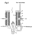
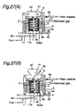
- a method for indirectly heating the shift reaction unit and the CO oxidation unit includes: (1) a method of using heat conduction in solid or radiant heat conducted from the outer periphery of the combustion chamber through an intervening medium (Figs. 1 to 7, and 27) and (2) a method of using heat of a burned exhaust gas flowing from the combustion chamber (Figs. 8 to 27).
- the reforming apparatus in which the shift reaction unit and the CO oxidation unit are indirectly heated by the method (1) may comprise the reforming reaction unit arranged around the combustion chamber in contact with an outer periphery of the combustion chamber and both of the shift reaction unit and the CO oxidation unit arranged around the reforming reaction unit.
- the reforming reaction unit forms the intervening medium, and heat from the combustion chamber is transmitted to the shift reaction unit and the CO oxidation unit after having been decreased through the reforming reaction unit.
- the steam reformation performed at the reforming reaction unit is an endothermic reaction
- heat from the combustion chamber decreases as a result of being consumed in the reforming reaction unit and thereafter conducts to the shift reaction unit and the CO oxidation unit.
- the reforming reaction unit, the shift reaction unit and the CO oxidation unit are arranged around the combustion chamber occupying the center of the reforming apparatus, it is effective for decreasing the height of the apparatus.
- a partition wall having a function of regulating heat transfer is interposed between the reforming reaction unit and both of the shift reaction unit and the CO oxidation unit.
- the above partition wall having a function of regulating heat transfer is intend to encompass any partition wall capable of regulating the temperature of heat to be transmitted down to the temperature range required by the shift reaction unit and the CO oxidation unit by decreasing the amount of heat transfer from the reforming reaction unit so that a residual heat of an unduly high temperature in the reforming reaction unit may be not transmitted directly to the shift reaction unit and the CO oxidation unit positioned outside thereof.
- This partition wall may comprise heat insulating materials, air layer or the like, and an optimum function of regulating heat transfer in the partition wall can be obtained by suitably selecting the kind of the material and thickness thereof.
- this reforming apparatus since the amount of heat transfer from the reforming reaction unit can be regulated by the partition wall, it is easy to control the temperature of the shift reaction unit and the CO oxidation unit.
- a flow path connecting between the reforming reaction unit and the shift reaction unit may detour outside both of the shift reaction unit and the CO oxidation unit.
- a reformed gas, immediately after emerging outwardly from the reforming reaction unit is usually higher in temperature than the required temperature in the shift reaction unit, but the reformed gas can dissipate heat if the flow path connecting between the reforming reaction unit and the shift reaction unit detours outside of the shift reaction unit and the CO oxidation unit and, therefore, the reformed gas can be controlled to a suitable range of temperature.
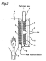
- the shift reaction unit is arranged on a side adjacent a high temperature zone of the reforming reaction unit and the CO oxidation unit is arranged on a side adjacent a low temperature zone of the reforming reaction unit, so as to be in conformity to a temperature distribution within the reforming reaction unit (see Fig. 2).
- the reforming apparatus in which the shift reaction unit and the CO oxidation unit are indirectly heated by the method (2), may comprise an exhaust chamber in which a burned exhaust gas from the combustion chamber directly flows, which the exhaust camber is positioned adjacent to and coaxially above the combustion chamber with the shift reaction unit arranged around the exhaust chamber and with the CO oxidation unit arranged around the shift reaction unit (see Figs. 8 to 26).
- the exhaust chamber is heated by a burned exhaust gas
- the shift reaction unit is heated by heat transferred from around the exhaust chamber
- the CO oxidation unit is heated by heat transferred from the shift reaction unit. Since at this time, the temperature of the burned exhaust gas becomes lower than that of the combustion chamber, the shift reaction unit can be heated to lower temperature than that of the reforming reaction unit, and the CO oxidation unit placed outermost of the apparatus can be heated to lower temperature than that of the shift reaction unit. Therefore, the temperature of each reaction unit can be controlled to that required by respective reaction unit.
- a first air intake for introducing the fresh air in between the combustion chamber and the exhaust chamber (Fig. 12). Since the reformed gas immediately after having engaged outwardly from the combustion chamber, has a temperature as high as the combustion chamber, but the temperature of the shift reaction unit can be controlled by suitably cooling the burned exhaust gas with the fresh air from the air intake to reduce the temperature of the exhaust gas before the latter is fed to the exhaust chamber.
- the secondary heating means can be used for heating the exhaust chamber when the temperature to which the shift reaction unit is heated is low, and also for preheating the shift reaction unit at an early stage of preparation of the reformed gas.
- the reforming apparatus may be a construction that includes an exhaust vent for discharging the burned exhaust gas in the exhaust chamber to the outside, a shutter means for selectively opening and closing the exhaust vent, a first duct which is separated from the exhaust chamber and interposed between the shift reaction unit and the CO oxidation unit, and a second duct which is fluid-connected with the first duct and arranged around the CO oxidation unit (Fig. 21).
- a burned exhaust gas in the exhaust chamber flows to the first duct when the shutter means closes the exhaust vent and further flows to the second duct.
- the shift reaction unit and the CO oxidation unit are also heated by the burned exhaust gas then flowing through the first and second duct.
- the temperature of each of the shift reaction unit and the CO oxidation unit can be freely controlled by selectively opening or closing the exhaust vent with the shutter means.
- a air intake for introducing the fresh air into the second duct (Fig. 22).
- the use of this air intake makes it possible to cool only the burned exhaust gas then flowing through the second duct with the fresh air introduced into the second duct when the exhaust vent is dosed by the shutter means, and therefore the CO oxidation unit can be more preferably controlled as to its temperature.
- At least one of the reforming reaction unit, the shift reaction unit and the CO oxidation unit is provided on a surface thereof with a heat transfer material having a higher heat conductivity than that of a material forming the surface (Fig. 15).
- Each reaction unit has a tendency to develop a varying temperature along the direction of flow of the gas.
- the reforming reaction unit has a tendency to exhibit a temperature drop on a leeward side thereof because of the endothermic reaction taking place therein
- the shift reaction unit and the CO oxidation unit have a tendency to exhibit a temperature rise on the respective leeward side thereof because of the exothermic reaction taking place therein.
- the heat transfer material provided on the surface of the reaction unit performs a role to level off the above difference in temperature.
- the CO oxidation unit may have an outer surface thereof provided with a fin for heat dissipation (Figs. 19 and 20).
- a fin for heat dissipation Figs. 19 and 20.
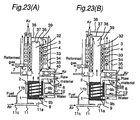
- the reforming apparatus in which the shift reaction unit and the CO oxidation unit are indirectly heated by the method (2) may have a construction that includes a main exhaust chamber in which a burned exhaust gas from the combustion chamber directly flows, a main exhaust vent for directly discharging the burned exhaust gas in the main exhaust chamber to the outside, a shutter means for selectively opening and closing the main exhaust vent, a first duct which is separated from the main exhaust chamber and fluid-connected thereto and is arranged around the main exhaust chamber, and a second duct which is fluid-connected with the first duct and arranged around the first duct, wherein the shift reaction unit is placed in the first duct and the CO oxidation unit is placed in the second duct (Figs. 23 to 26).
- each reaction unit can be more preferably controlled as to its temperature by keeping the main exhaust vent in an opened position.
- This reforming apparatus can include an exhaust sub-vent for discharging a burned exhaust gas within the first duct to the outside, and a shutter means for selectively opening and closing the exhaust sub-vent (Figs. 21 to 26).
- a burned exhaust gas slightly flows to the first duct from a separating portion between the main exhaust chamber and the first duct, and then discharged from the exhaust sub-vent.
- the burned exhaust gas slightly flowing through the first duct works to heat the shift reaction unit to a somewhat higher temperature range than that in the CO oxidation unit. Therefore, each reaction unit can be more preferably controlled as to its temperature.
- At least one of the shift reaction unit and the CO oxidation unit is formed into a coil-like shape (Figs. 23 to 26).
- the shift reaction unit and the CO oxidation unit is formed into a coil-like shape, efficiency of heat exchange becomes good when the shift reaction unit and the CO oxidation are heated by a burned exhaust gas.
- the CO oxidation unit can be temperature-controlled by the fresh air introduced from the air feed channel into the second duct into.
- a raw material feed channel for feeding the raw material and steam to the raw material reforming unit is arranged in a position in which the raw material and the steam are preheated by heat from the heat source of the raw material reforming unit (Figs. 3 to 27).
- the raw material reforming unit is fed with the raw material and steam which are in a state of mixture through the raw material feed channel
- the capability of the raw material feed channel being preheated facilitates generation of steam from water in the raw material feed channel and, therefore, water rather than steam can be supplied from a source of the raw material to the raw material feed channel.
- This dispenses with necessity of use of a separate steam generating apparatus and, consequently, a reforming system can be downscaled as a whole.
- the reformation reaction in the raw material reforming unit can be immediately initiated in an early state of the raw material reforming unit without the temperature of a reformation catalyst therein being lowered.
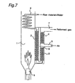
- the method for preheating the raw material feed channel is not limited to specified one, another preheating method may be employed in which, for example, at least a portion of the raw material feed channel is held in contact with the surface of at least one of the reforming reaction unit, the shift reaction unit and the CO oxidation unit (Figs. 3 to 6, 8 to 24, and 26); at least a portion of the raw material feed channel is arranged at a position contactable with the burned exhaust gas from the heat source of the raw material reforming unit (Fig. 7); or at least a portion of the raw material feed channel is arranged at such a position that it can be directly heated by the heat source of the raw material reforming unit (Figs. 25 and 27).
- the heat source of the raw material reforming unit generates heat by catalytic combustion
- the combustion do not start until when temperature of the combustion catalyst rises up to some degree but, the combustion reaction can start immediately in early time of beginning combustion if the combustion catalyst is preheated by the preheating means in advance.
- the reforming apparatus according to the present invention is particularly effective where the raw material to be reformed is employed of a kind which the reactive temperature of reformation reaction thereof is in a high temperature range.
- the reforming reaction unit is heated to the range of 400 to 1000 °C; the shift reaction unit is heated to the range of 200 to 350 °C; and the CO oxidation unit is heated to the range of 100 to 250 °C.
- the reactive temperature of the reforming reaction unit is in the high temperature range like this case, a difference between reactive temperature required in the reforming reaction unit and that required in the shift reaction unit and the CO oxidation unit becomes so large that the temperature control thereof becomes difficult to accomplish.
- the temperature of the reforming reaction unit can be easily controlled to the high temperature range, and that of the shift reaction unit and the CO oxidation unit can also be easily controlled to the low temperature range.
- the reforming apparatus according to a first preferred embodiment of the present invention will first be described.
- the first embodiment of the present invention provides a basic structure of the reforming apparatus while a group of the first to seven embodiments of the present invention make use of component parts of the reforming apparatus that are similar to those employed in the basic structure according to the first embodiment of the present invention.
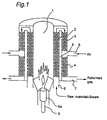
- the reforming apparatus comprises, as shown in Fig. 1, a generally cylindrical combustion chamber 1 which serves as a heat source, surrounded by a reforming reaction unit 2 for reforming a steam-reforming a reforming raw material to generate a reformed gas containing hydrogen as a principal component.
- the reforming reaction unit 2 is in turn surrounded by a shift reaction unit 3 for reducing CO, contained in the reformed gas generated by the reforming reaction unit 2, by the water shift reaction and a CO oxidizing unit 4 for oxidizing the CO component, contained in the reformed gas after treatment in the shift reaction unit 3, to thereby further reduce the CO component.
- the reforming reaction unit 2, the shift reaction unit 3 and the CO oxidizing units 4 are separate units and arranged in coaxial relation to each other.
- the combustion chamber 1 is of a generally cylindrical shape and is positioned centrally of the reforming apparatus. This combustion chamber 1 has a top end opening outwardly and a bottom end accommodating a burner 9a which serves as a combustion means 9. It is, however, to be noted that the combustion chamber 1 may not be limited to the cylindrical shape, but may have a polygonal cross-unit and that the combustion means 9 may comprise, other than the burner 9a, any suitable means such as, for example, a catalytic combustion means.
- the reforming reaction unit 2 has an annular gas passage defined by an annular layer exterior around an outer periphery of the combustion chamber 1 and filled with a reforming catalyst and is adapted to be heated directly from the combustion chamber 1. Also, the reforming reaction unit 2 is provided with a raw material supply path 6 for supplying the reforming raw material and the steam. In the first embodiment of the present invention, the raw material supply path 6 is connected with a bottom end of the reforming reaction unit 2.
- the reforming catalyst referred to above is of a kind effective to induce a so-called steam reforming reaction in which the reformed gas containing hydrogen as a principal component can be generated by causing the reforming raw material and the steam contact each other under the elevated temperatures, and may be employed in the form of a carrier made of, for example, alumina or zirconium, and deposited with metal such as, for example, Ni, Rh and/or Ru.
- the reforming reaction unit 2 is of a design in which a gaseous mixture of the reforming raw material and the steam can pass through interstices among particles of the reforming catalyst, at which time the gaseous mixture contacts the reforming catalyst particles to initiate the steam reforming reaction to generate the reformed gas rich of hydrogen.
- this reformed gas In addition to the hydrogen, this reformed gas contain carbon dioxide, carbon monoxide, methane and so on.
- This steam reforming reaction is an endothermic reaction and a direct heating by the effect of heats from the combustion chamber 1 therefore provides a reaction heat.
- the steam reforming reaction occurs favorably generally if the reaction temperature is chosen to be of a value equal to or higher than 500°C.
- the reforming raw material referred to above may comprise a gas of a hydrocarbon system such as, for example, a gaseous methane, propane or butane, or alcohol, gasoline, kerosene or naphtha which exhibits a liquid phase at room temperatures.
- the steam reforming reaction referred to above results in generation of the reformed gas in which about 70% of hydrogen, about 15% of carbon dioxide, about 10% of carbon monoxide and several percents of methane and others are mixed together.
- the heating temperature of this reforming reaction unit 2 can be controlled by suitably adjusting the size or the like of flames of the burner 9a.
- the shift reaction unit 3 and the CO oxidizing unit 4 are positioned radially outwardly of the reforming reaction unit 2 with a partition wall 8 intervening therebetween.
- the shift reaction unit 3 is formed in a top aloof portion of a gas passage defined by an annular layer exteriorly around the reforming reaction unit 2, which top aloof portion is communicated with the reforming reaction unit 2 and filled with a shift catalyst.
- the CO oxidizing unit 4 is formed in a bottom lee portion of the gas passage spaced a distance downwardly from the shift reaction unit 3 and filled with a CO oxidizing catalyst.
- a connection between the shift reaction unit 3 and the CO oxidizing unit 4 is provided with an air supply passage 5 through which air can be supplied.
- the shift reacting unit 3 is arranged exteriorly around a top region of the reforming reaction unit 2 with its top communicated with the top of the reforming reaction unit 2
- the CO oxidizing unit 4 is arranged exteriorly around a bottom region of the reforming reaction unit 2 with its top fluid-connected with a bottom of the shift reaction unit 3.
- the CO oxidizing unit 4 has a bottom provided with a reformed gas discharge passage 7 through which the reformed gas with the CO component having been removed therefrom can be discharged.
- the shift catalyst referred to above is used to reduce the CO content in the reformed gas, generated in the reforming reaction unit 2, by the water shift reaction and may be employed in the form of a carrier made of, for example, alumina or zirconium and deposited with, for example, Cu, Zn, Fe and/or Cr.
- the reformed gas generated in the reforming reaction unit 2 contacts the shift catalyst wherefore the shift reaction in which the carbon monoxide content in the reformed gas react with the steam to generate hydrogen and carbon dioxide takes place, and therefore, a major portion of the carbon monoxide contained in the reformed gas can reduced down to, for example, a density of about 1%.
- the shift reaction referred to above is an endothermic reaction that takes place at a temperature lower than the steam reforming reaction taking place in the reforming reaction unit 2.
- the reaction takes place at a reaction temperature of about 200 to 350°C and preferably 220 to 300°C.
- the CO oxidizing catalyst is used to selectively oxidize a CO content remaining in the reformed gas which has been treated in the shift reaction unit 3 and may be employed in the form of a carrier made of alumina or zirconium and deposited with, for example, Pt and/or Ru.
- the CO oxidizing unit 4 the reformed gas from which the CO content has been reduced in the shift reaction unit 3 is, after having been mixed with the air (oxygen) supplied through the air supply passage 5, brought into contact with the CO oxidizing catalyst so that it can be selectively oxidized to generate carbon dioxide which is then removed.
- the density of the CO content in the reformed gas is further reduced down to, for example, about 100 ppm or lower.
- the oxidizing reaction brought about by the CO oxidizing catalyst with the carbon monoxide is an endothermic reaction which takes place at a reaction temperature lower than the shift reaction, for example, at a reaction temperature of about 100 to 250°C and preferably about 120 to 180°C.
- the partition wall 8 intervening between the reforming reaction unit 2 and both of the shift reaction unit 3 and the CO oxidizing unit 4 has a capability of self-adjusting thermal conduction, that is, a capability of transmitting a controlled quantity of heats from the reforming reaction unit 2 to the shift reaction unit 3 and the CO oxidizing unit 4, without allowing the after-heat from the reforming reaction unit 2 to remain excessively high before it is transmitted to the shift reaction unit 3 and the CO oxidizing unit 4, so that the shift reaction unit 3 and the CO oxidizing unit 4 can be heated to the respective reaction temperatures.
- the partition wall 5 having such a thermal conductivity self-adjusting capability may be in the form of, for example, any known adiabatic layer or a hollow layer and, by suitably adjusting the material and the thickness thereof, an optimum thermal conduction adjusting effect can be obtained.
- the reforming apparatus comprises a coaxial arrangement of the combustion chamber 1, the reforming reaction unit 2 and both of the shift reaction unit 3 and the CO oxidizing unit 4 with the combustion chamber 1 inside the reforming reaction unit 2, the reforming system for providing the reformed gas with the CO content removed can be assembled compact. Also, since heat from the combustion chamber 1 is consumed by the reforming reaction unit 2 in which the steam reforming reaction which is the endothermic reaction under the elevated temperatures takes place, after-heat of which is transmitted indirectly to both of the shift reaction unit 2 and the CO oxidizing unit 4 and, since the heat from the combustion chamber 1 can thus be utilized effectively by the reforming reaction unit 2, the shift reaction unit 3 and the CO oxidizing unit 4, the loss of heat can be minimized advantageously.
- the reforming reaction unit 2 and both of the shift reaction unit 3 and the CO oxidizing unit 4 are coaxial with each other, they can be arranged in equilibrium relatively to the combustion chamber 1, serving as the heat source, without being biased even slightly relative to the combustion chamber 1 and, consequently, any possible variation in temperature within the same reaction unit can advantageously minimized.
- heat conducted from the reforming reaction unit 2 is, after the temperature thereof has been adjusted by the partition wall 5 to the proper value, transmitted to the shift reaction unit 3 and the CO oxidizing unit 4 within which the respective reactions take place at a temperature lower than that in the reforming reaction unit 2 and, therefore, the respective reaction within the shift reaction unit 3 and the CO oxidizing unit 4 can take place at the properly controlled temperatures.
- This reforming apparatus is of a structure as shown in Fig. 2 wherein the reforming reaction unit 2 and the shift reaction unit 3 are connected by a flow path 10 detouring outside both of the shift reaction unit 3 and the CO oxidation unit 4, which is different part from the embodiment 1.
- the shift reaction unit 3 is positioned outside the lower part of the reforming reaction unit 2, while the CO reaction unit 4 is positioned outside the upper part of the reforming reaction unit 2.
- the upper end of the reforming reaction unit 2 and the lower end of the shift reaction unit 3 is connected by the detouring flow path 10, and a supply exit 7 of the reformed gas is provided at the upper end of the CO oxidation unit 4.
- the high temperature reformed gas from discharges heat in the detouring flow path 7, so that the temperature of the reformed gas comes down to a reaction temperature of the shift reaction unit 3. Then, the reformed gas is supplied to the shift reaction unit, by which a good shift reaction may go in the shift reaction unit 3.
- the positioning of the shift reaction unit 3 and the CO reaction unit 4 outside the reforming reaction unit 2 makes the temperature distribution of the shift reaction unit 3 and the CO reaction unit 4 corresponded to that of the reforming reaction unit 2. That is, the lower side of the reforming reaction is a higher temperature zone because of nearer situation from a burner 9 in the combustion chamber 1 while the upper side is a lower temperature zone because of farther situation from the burner 9. As explained above, the reaction temperature of the shift reaction unit 3 is higher than that of the CO reaction unit 4, so that the structure makes it easy to control the temperature of the shift reaction unit 3 and the CO reaction unit 4.
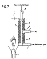
- This reforming apparatus is of a structure, as shown in Fig.3, in which a raw material supply path 6 is running from the upper side to the lower side of a partition wall 8 interposed between the reforming reaction unit 2, the shift reaction unit 3 and the CO reaction unit 4, which is a different part from the embodiment 1.
- a raw material supply path 6 is running from the upper side to the lower side of a partition wall 8 interposed between the reforming reaction unit 2, the shift reaction unit 3 and the CO reaction unit 4, which is a different part from the embodiment 1.
- mixture of raw materials and steam flowing through the supply path 6 is preheated by the reforming reaction unit 2 and then supplied to the reforming reaction unit 2, so that the mixture entering into the reforming reaction unit 2 is easy to be heated to a reaction temperature zone in a good controlled manner.
- water supplied together with raw materials can be evaporated so that no steam generator is provided therein.
- This reforming apparatus is of a structure, as shown in Fig.4, in which the reforming reaction unit 2, the shift reaction unit 3, the CO reaction unit 4 and the raw material supply path 6 are arranged in an upside-down manner of the third embodiment. That is, the shift reaction unit 3 is arranged on an outer peripheral side of the lower part of the reforming reaction unit 2 while the CO reaction unit 4 is arranged on an outer peripheral side of the upper part of the reforming reaction unit 2.
- the raw material supply path 6 interposed in the partition wall 8 is running from the lower side thereof to the upper side thereof and connected to the upper end of the reforming reaction unit 2. Therefore, in the same manner as the third embodiment, the raw material supply path 6 can be preheated by heat of the reforming reaction unit 2. Further in the same manner as the second embodiment, the shift reaction unit 3 and the CO oxidation unit 4 are arranged in conformity to the temperature distribution of the reforming reaction unit 2. Accordingly, a better temperature control can be obtained in each of the units.
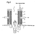
- This reforming apparatus is of a structure, as shown in Fig. 5, in which the raw material supply path 6 interposed in the partition wall in the third embodiment is attached in a coil pattern around the reforming reaction unit 2.
- the structure is sufficient to preheat the raw material supply path 6 and is a same function of regulating heat transfer as that of the partition wall 8. That is, the mixture of raw material and steam can absorb heat from the reforming reaction unit 2, by which the heat transfer to the shift reaction unit 3 and the CO oxidation unit 4 can be regulated.
- This reforming apparatus is of a structure,as shown in Fig,6, in which in the first embodiment the raw material supply path 6 is a coil pattern arranged around the outer side of the shift reaction unit 3 and the CO oxidation unit 4.
- the structure is sufficient to preheat the raw material supply path 6 by heat of the shift reaction unit 3 and the CO oxidation unit 4. Utilization of extra heat from the shift reaction unit 3 and the CO oxidation unit 4 for preheating the raw material supply path 6 realizes effective use of heat source and decreases heat loss.
- This reforming apparatus is of a structure, as shown in Fig.7, in which in the first embodiment, the reforming reaction unit 2, the shift reaction unit 3 and the CO oxidation unit 4 are arranged in an upside-down manner and an introduction part of the raw material supply path 6 is arranged in a coil pattern and positioned at the upper side of the combustion chamber 1 while an exit end of the raw material supply path 6 is connected to the upper side of the reforming reaction unit 2.
- the structure is sufficient to preheat the raw material supply path 6 by the exhaust gas heat of the combustion chamber 1, so that utilization of extra heat from the combustion chamber for preheating the raw material supply path 6 realizes effective use of heat source and decreases heat loss.
- the reforming apparatus according to an eighth preferred embodiment of the present invention will be described.
- the eighth embodiment of the present invention provides a basic structure of the reforming apparatus while a group of eighth to twentieth embodiments of the present invention make use of component parts of the reforming apparatus that are similar to those employed in the basic structure according to the eighth embodiment of the present invention.
- the reforming apparatus comprises, as shown in Fig. 8, a generally cylindrical combustion chamber 1 arranged with its longitudinal axis oriented vertically, and a reforming reaction unit 2 in the form of a coil surrounding around and in contact with the combustion chamber 1.
- the combustion chamber 1 has an upper portion formed with an exhaust chamber 14 coaxial with the combustion chamber 1 for allowing a combustion exhaust gas to flow upwardly therethrough from the combustion chamber 1.
- a shift reaction unit 3 is disposed so as to surround around the exhaust chamber 14, and a CO oxidizing unit 4 is disposed radially outwardly of the shift reaction unit 3 with an airspace 15 defined between it and the shift reaction unit 3.
- the reforming reaction unit 2 has a lower end fluid-connected with a raw material supply path 6.
- This raw material supply path 6 includes a raw material pipe 6a for the supply of only a reforming raw material therethrough and a steam pipe 6b for the supply of a steam (water) therethrough, both of said pipes 6a and 6b being joined together on their length.
- the steam pipe 6b has a portion disposed having been coiled around and in contact with the outer periphery of the reforming reaction unit 2 so that it can be preheated by heat evolved from the reforming reaction unit 2.
- the reforming reaction unit 2 has an upper end fluid-connected with a lower end of the shift reaction unit 3 through a connection tube 12.
- the shift reaction unit 3 has an upper end fluid-connected with an upper end of the CO oxidizing unit 4 through a connection tube 13.
- This connection tube 13 is provided with an air supply passage 5 for the introduction of air necessitated by and in the CO oxidizing unit 4.
- the combustion chamber 1 is filled therein with a combustion catalyst 9b as a combustion means 9.
- the combustion catalyst 9b may be employed in the form of a carrier deposited with, for example, Pt, Ru, Pd and/or Rh.
- the combustion chamber 1 has a lower end fluid-connected with a fuel supply passage 11 for the supply of a fuel and a combustion chamber of ruse in combustion.
- This fuel supply passage 11 has a hole 11 a defined at a location adjacent an entrance to the combustion chamber 1 so that the gaseous fuel can be supplied uniformly into the combustion chamber 1. It is to be noted that in the combustion chamber 1 a burner may be employed as the combustion means 9.
- the operation of the reforming apparatus will now be described.
- the gaseous fuel and the air are supplied from the fuel supply passage 11 into the combustion chamber 1 and are burned in contact with the combustion catalyst 9b to emit heat.
- An exhaust gas produced as a result of combustion in the combustion chamber 1 is discharged to the outside through the exhaust chamber 14.
- a mixture of a reforming material and a steam is supplied from the raw material supply path 6 into the reforming reaction unit 2.
- the liquid phase is supplied into the steam pipe 6b, this liquid phase is preheated by heat evolved from the reforming reaction unit 2 to transform into a steam which is subsequently mixed with the reforming raw material.
- the reforming raw material is transformed in the reforming reaction unit 2 into a reformed gas containing CO and, as the reformed gas flow successively through the shift reaction unit 3 and the CO oxidizing unit 4, the CO component is removed to provide a reformed gas that is subsequently delivered outwardly from the reformed gas discharge passage 7.
- the reforming reaction unit 2 is directly heated from the combustion chamber 1 and is then controlled to attain the maximum possible temperature whereas the shift reaction unit 3 is heated from the exhaust chamber 14, in which the combustion exhaust gas flows, and is controlled to a temperature lower than that of the reforming reaction unit 2 and, on the other hand, the CO oxidizing unit 4 is heated by a heat conduction from the shift reaction unit 3 and is controlled to a temperature lower than that of the shift reaction unit.
- the reforming reaction unit 2 is directly heated and both of the shift reaction unit 3 and the CO oxidizing unit 4 are heated indirectly, wherefore a favorable temperature control is possible and, since these reaction units are coaxially arranged with respect to each other, a temperature variation is minimized. It is to be noted that the control of the temperature of the CO oxidizing unit 4 can be facilitated if a cooling air is applied by, for example, a fan disposed externally.
- This reforming apparatus is of a structure as shown in Fig. 9 wherein in the eighth embodiment an incombustable core 16 is disposed centrally within the combustion chamber 1.
- This core 16 has a hollow and has a small heat capacity. Because of the presence of the core 16, a gas flow passage inside the combustion chamber 1 is constricted to allow the flow to be accelerated, wherefore the efficiency of heat exchange between the reforming reaction unit 2 and the combustion gas can be increased.
- the reforming reaction unit 2 is heated mainly by the combustion gas flowing around and in the vicinity of the combustion chamber 1 and the combustion gas flowing centrally within the combustion chamber 1 does not participate so much in heating the reforming reaction unit 2 and has a high possibility of being discharged outwardly from the combustion chamber 1, the heat loss can be reduced by allowing the core 16 to occupy a central region of the combustion chamber 1 to thereby concentrate the flow of the combustion chamber around and in the vicinity of the combustion chamber 1.
- This reforming apparatus is of a structure, as shown in Fig. 10, in which in the eighth embodiment an incombustable core 17 is disposed centrally within the exhaust chamber 4.
- This core 17 has a hollow and has a small heat capacity.
- the role of this core 17 is similar to that in the ninth embodiment to constrict a gas flow passage inside the exhaust chamber 4 for the passage of the combustion exhaust gas to allow the flow to be accelerated, wherefore the efficiency of heat exchange between it and the shift reaction unit 3 can be increased.
- the core 17 prevents the combustion gas from flowing into a center region of the exhaust chamber 14 which does little participate in heating of the shift reaction unit 3, to thereby reduce the heat loss.
- This reforming apparatus is of a structure, as shown in Fig. 11, in which in the eighth embodiment the cores 16 and 17 are disposed centrally within the combustion chamber 1 and the exhaust chamber 4, respectively. With this reforming apparatus, cumulative effects similar to those described in connection with the ninth and tenth embodiments can be obtained.
- This reforming apparatus is of a structure, as shown in Figs. 12 and 13, in which in the eighth embodiment an air intake unit 18 is disposed between the combustion chamber 1 and the exhaust chamber 14 for the introduction of an external air. More specifically, this air intake unit 18 includes an annular flow passage 18 extending around a junction between the combustion chamber 1 and the exhaust chamber 14, and a circular row of openings 18a opening at the junction so that the air drawn from the air intake unit 18 can be introduced uniformly into the passage for the flow of the combustion exhaust gas through the annular flow passage 18 by way of the circular row of the openings 18a.
- reference numeral 11b represents a fuel pipe through which only the gaseous fuel can be introduced into the fuel supply passage 11
- reference numeral 11c represents an air tube through which air for combustion use can be introduced into the fuel supply passage.
- reference numeral 50 represents a manhole through which a temperature detecting means such as, for example, a thermocouple can be inserted in the reforming reaction unit 2
- reference numeral 51 represents a thermocouple manhole through which a temperature detecting means such as, for example, a thermocouple can be inserted in the CO oxidizing unit 4
- reference numeral 52 represents a thermocouple manhole through which a temperature detecting means such as, for example, a thermocouple can be inserted in the shift reaction unit 3
- reference numeral 53 represents a filling port for the reforming catalyst.
- This reforming apparatus is of a structure, as shown in Fig. 14, in which in the twelfth embodiment the cores 16 and 17 are disposed centrally within the combustion chamber 1 and the exhaust chamber 14, respectively. In this case, cumulative effects similar to those described in connection with the eleventh and twelfth embodiments can be obtained.
- This reforming apparatus is of a structure, as shown in Fig. 13, in which in the eleventh embodiment a heat conductive material 19 having a higher heat conductivity than that exhibited by the material forming a surface of each of the reforming reaction unit 2, the shift reaction unit 3 and the CO oxidizing unit 4 is disposed on such surface.
- This heat conductive material 19 serves to uniformalize the distribution of temperature in each of the reaction units with respect to the direction of flow of the gas.
- the temperature difference tends to be created in a direction conforming to the direction of flow of the gas in such a way that, for example, since in the reforming reaction unit 2 an endothermic reaction takes place, the temperature on an leeward side tends to lower whereas since in the shift reaction unit 4 and the CO oxidizing unit 4 a exothermic reaction takes place, the temperature on a windward side tends to increase.
- the heat conductive material 19 provided on the respective surfaces of the reaction units serves to uniformalize this temperature difference by heat conduction.
- the surface material of the reaction units although sufficient if it has a high heat conductivity, is used in the form of, for example, stainless steel in view of the fact that a corrosion resistance and a durability are required as well and, in contrast thereto, the heat conductive material 19 is employed in the form of copper or aluminum. Although they are inferior in that the heat resistance and the strength are lower than those of the stainless steel, they are excellent in heat conductivity.
- the reforming apparatus is of a structure, as shown in Fig. 16, in which in the twelfth embodiment the core 16 is disposed centrally within the combustion chamber 1 and a burner 20 as an auxiliary heating means is disposed within a junction between the combustion chamber 1 and the exhaust chamber 14 for heating the exhaust chamber 14.
- reference numeral 21 represents an igniter for the burner 20. This burner 20 is used to heat the exhaust chamber 14 when the heating temperature of the shift reaction unit 3 is low and can also be used to preheat the shift reaction unit 3 at an initial stage of formation of the reformed gas.
- This reforming apparatus is of a structure, as shown in Fig. 17, in which in the fifteenth embodiment a filling unit for accommodating a combustion catalyst 22 is disposed within the exhaust chamber 14 and a catalyst net 23 made of a combustion catalyst is provided at an entrance to the exhaust chamber 14.
- the burner 20 can be used not only in a manner similar to that used in the fifteenth embodiment, but also as an auxiliary heating means for the exhaust chamber 14 by initially heating the catalyst net 23 and the combustion catalyst 22 by means of flames from the burner 20. It is to be noted that for combustion of the combustion catalyst 22, the burner 20 and the fuel supplied from the air intake unit 18 and oxygen, remaining in the combustion exhaust gas from the combustion chamber 1, and air supplied from the air intake unit 18 are utilized.
- This reforming apparatus is of a structure, as shown in Fig. 18, in which in the eighth embodiment as a preheating means for preheating the combustion catalyst 9b within the combustion chamber 1 a catalyst net made of combustion catalyst is provided at an entrance to the combustion chamber 1 and an ignition device 24 is provided in the fuel supply passage 6.
- the heat generating source in the combustion chamber 1 is a combustion of the catalyst
- no combustion reaction is initiated if the temperature of the combustion catalyst 9 is increased a certain extent
- the gaseous fuel is ignited by the ignition device 24 to cause the catalyst net 25, that is relatively easy to be heated, to initiate the combustion reaction to thereby preheat the combustion catalyst 9 so that at an initial stage of the beginning of the combustion, combustion can be initiated immediately.
- This reforming apparatus is of a structure, as shown in Fig. 19, in which in the eighth embodiment cooling fins 26 are disposed around the CO oxidizing unit 4.
- the temperature control of the CO oxidizing unit 4 that is one of the various reaction units which requires a lower reaction temperature of all, can be carried out by causing heat to be dissipated by the cooling fins 26.
- the amount of heat dissipated from the cooling fins 26 can be adjusted by suitably selecting the number and/or length of each fin and/or selecting a manner in which a cooling wind is applied. Also, as shown in Figs. 20(A) and 20(B), by varying the height of the cooling fins 26 along the direction of flow of the gas in the CO oxidizing unit 4, the pattern of distribution of temperature within the CO oxidizing unit 4 can be redressed.
- This reforming apparatus is of a structure, as shown in Fig. 21, in which in the twelfth embodiment, a lid 28 is provided at an exhaust port 27, through which a combustion gas within the exhaust chamber 14 can be discharged to the outside, for selectively opening and closing the exhaust port 27 and, on the other hand, a first duct 29 branched from and communicated with the exhaust chamber 14 is defined between the shift reaction unit 3 and the CO oxidizing unit 4 and a second duct 30 communicated with the first duct 29 is formed externally around the CO oxidizing unit 4.
- the first duct 29 is communicated with an upper end of the exhaust chamber 14, and the second duct is communicated at a lower end with a lower end of the first duct 29.
- the second duct 30 has an upper end open to the outside for discharge of the exhaust gas.
- This reforming apparatus is of a structure, as shown in Fig. 22, in which in the nineteenth embodiment, an air intake unit 31 for introducing an external air into the second duct 30 is employed.
- This air intake unit 31 opens at a communication between the first and second ducts 29 and 30 to introduce the external air thereto. In such case, by introducing the external air from the air intake unit 31 into the second duct 20, the CO oxidizing unit 4 can be cooled to accomplish a temperature control thereof.
- This twenty-first embodiment provides a basic structure of the reforming apparatus while a group of twenty-first to twenty-fourth embodiments of the present invention make use of component parts of the reforming apparatus that are similar to those employed in the basic structure according to the twenty-first embodiment of the present invention.
- the reforming apparatus comprises, as shown in Figs. 23(A) and 23(B), a generally cylindrical combustion chamber 1 arranged with its longitudinal axis oriented vertically, and a reforming reaction unit 2 in the form of a coil accommodated coaxially within the combustion chamber 1.
- the combustion chamber 1 has an upper portion formed with a main discharge port 36 that is provided with a first lid 37 serving as a sluice means for selectively opening and closing the main discharge port 36.
- a main exhaust chamber 32 is externally surrounded by a first duct 33 communicated with the main exhaust chamber 32 through a branch off from the main exhaust chamber 32, which duct 33 is in turn surrounded by a second duct 34 communicated with the first duct 33.
- a shift reaction unit 3 is disposed within the first duct 33 and a CO oxidizing unit 4 is disposed within the second duct 34.
- the combustion chamber 1 is filled with a combustion catalyst 9b serving as a combustion means 9.
- the combustion chamber 1 has a lower end fluid-coupled with a fuel supply passage 11 for supplying therethrough a gaseous fuel and an air for use in combustion.
- This fuel supply passage has a hole 11 a defined at a location adjacent an entrance to the combustion chamber 1 so that the gaseous fuel can be supplied uniformly into the combustion chamber 1. It is to be noted that in the combustion chamber 1 a burner may be employed as the combustion means 9.
- the reforming reaction unit 2 comprises a coiled pipe filled with a reforming catalyst and has an upper end portion led outwardly from an upper portion of the combustion chamber 1 and fluid-connected with a raw material supply path 6.
- This raw material supply path 6 includes a raw material pipe 6a for the supply of only a reforming raw material therethrough and a steam pipe 6b for the supply of a steam (water) therethrough, both of said pipes 6a and 6b being joined together on their length.
- the steam pipe 6b has a portion disposed having been coiled around and in contact with the outer periphery of the combustion chamber 1 so that it can be preheated by heat evolved from the combustion chamber 1.
- the reforming reaction unit 2 has a lower end portion led outwardly from a lower end of the combustion chamber 1 and is in turn fluid-connected with a connection tube 12 that connects the reforming reaction unit 2 and the shift reaction unit 3 together.
- the shift reaction unit 3 is in the form of a coiled pipe filled with a shift catalyst therein and is introduced within the first duct 33 so as to extend from bottom to top while being wound spirally in the first duct 33.
- the connection tube 12 referred to above is fluid-connected with a lower end of the shift reaction unit 3.
- the CO oxidizing unit 4 is in the form of a coiled pipe filled with a CO oxidizing catalyst therein and is introduced within the second duct 34 so as to extend from top to bottom while being wound spirally in the second duct 34.
- the CO oxidizing unit 4 has an upper end portion fluid-connected with an upper end portion of the shift reaction unit 3 through a connection tube 13.
- This connection tube 13 is provided with an air supply passage 5 for the introduction of air necessitated by and in the CO oxidizing unit 4.
- the CO oxidizing unit 4 has a lower end portion fluid-connected with a reformed gas discharge passage 7 for drawing the reformed gas outwardly therethrough.
- the first duct 33 is communicated at a lower end thereof with the main exhaust chamber 32 and at an upper end thereof with the second duct 34. Also, a sub-discharge port 39 for the discharge of a combustion exhaust gas inside it to the outside thereof is provided on the upper end of the first duct 33.
- the second duct 34 has an outer periphery formed with a third duct 35 that is communicated with the second duct 34 at a lower end thereof.
- the second and third ducts 34 and 35 have their upper ends open to the outside.
- the second duct 32 has a lower end provided with an air supply passage 40 through which an external air is introduced into it.
- the main discharge port 36 at the upper end of the main exhaust chamber 32 is positioned at a level somewhat lower than the level of the respective upper ends of the first to third ducts.
- the reforming apparatus has an upper end provided with a second lid 38 detachably mounted thereon so as to overlay an upper region of the main discharge opening 36 and the respective upper ends of the first and second ducts.
- the reforming reaction unit 2 is exposed to and hence heated by the combustion gas of an elevated temperature within the combustion chamber 1, and the shift reaction unit 3 inside the first duct 33 and the CO oxidizing unit 4 inside the second duct 34 are heated by the combustion exhaust gas emerging outwardly from the combustion chamber 1. In this way, each of the reaction units is preheated.
- the shift reaction unit 3 has a temperature controlled to a value lower than that of the reforming reaction unit 2.
- the CO oxidizing unit 4 is heated by the radiation and heat transmission in solid from the shift reaction unit 3 and heat evolved in the reforming gas itself then flowing therein.
- This CO oxidizing unit 4 has a temperature controlled to a value lower than that of the shift reaction unit 3 since it is not heated by the combustion exhaust gas and, also, the radiation and the heat transmission in solid have been weakened.
- the external air has to be introduced from the air supply passage 40 into the second duct 34. It is to be noted that the timing at which the first and second lids 37 and 38 are opened or closed is adjustable as desired.
- both of the reforming reaction unit 2 and the shift reaction unit 3 and the CO oxidizing unit 4 can be preheated by effecting combustion within the combustion chamber 1 while the first and second lids 37 and 38 have been dosed, whereas during routine run of the apparatus, the first and second lids 37 and 38 are opened to allow the temperature of each of the units to be controlled optimally.
- This reforming apparatus is of a structure in which in the twenty-first embodiment, an incombustable core 16 is disposed centrally within the combustion chamber 1 as shown in Fig. 24. Because of the presence of the incombustable core 16, a gas flow passage inside the combustion chamber 1 is constricted to allow the flow to be accelerated, wherefore the efficiency of heat exchange between the reforming reaction unit 2 and the combustion gas can be increased. Also, in the combustion chamber 1, the combustion catalyst 9b is filled only in a lower portion of the combustion chamber 1. In other words, even though the combustion catalyst 9b is not filled entirely within the combustion chamber 1, the combustion reaction proceeds sufficiently and, therefore, the loss of pressure of the combustion gas can be reduced by elimination of an excessive quantity of the combustion catalyst 9b.
- This reforming apparatus is of a structure wherein in the twenty-first embodiment, a hollow core 16 is disposed centrally within the combustion chamber 1, as shown in Fig. 25, so that the hollow of the core 16 can be used as the raw material supply path 6 for supplying both of the reforming raw material and the steam into the reforming reaction unit 2.
- the steam can also be generated inside the core 16.
- This reforming apparatus is, as shown in Fig. 26, of a structure in which in the twenty-second embodiment the core 16 is used as the fuel supply passage 11 so that both of the fuel and the combustion air can be supplied to the combustion catalyst 9b within the combustion chamber 1.
- the combustion reaction by the combustion catalyst 9 can be accelerated favorably.
- This reforming apparatus comprises, as shown in Figs. 27(A) and 27(B), a generally cylindrical combustion chamber 1 arranged with its longitudinal axis oriented vertically, and a reforming reaction unit in the form of a coil accommodated coaxially within the combustion chamber 1.
- the combustion chamber 1 has an upper portion formed with a main discharge port 41 for the direct discharge of the combustion exhaust gas from the combustion chamber 1 to the outside, which port 41 is provided with a lid 42 serving as a sluice means for selectively opening and closing the main discharge port 41.
- the combustion chamber 1 has an outer perimeter surrounded by a first duct 43 communicated at a top portion of a side wall of the combustion chamber 1, which is in turn surrounded by a second duct 44 communicated with a lower end portion of the first duct 43.
- a shift reaction unit 3 in the form of a coil is disposed within the first duct 43 and a CO oxidizing unit 4 in the form of a coil is disposed within the second duct 44.
- the combustion chamber 1 is filled with a combustion catalyst 9b serving as a combustion means 9.
- the combustion chamber 1 has a lower end fluid-coupled with a fuel supply passage 11 for supplying therethrough a gaseous fuel and a combustion air for use in combustion.
- This fuel supply passage 11 has a hole 11a defined at a location adjacent an entrance to the combustion chamber 1 so that the gaseous fuel can be supplied uniformly into the combustion chamber 1. It is to be noted that in the combustion chamber 1 a burner may be employed as the combustion means 9.
- the reforming reaction unit 2 comprises a coiled pipe filled with a reforming catalyst and has an upper end portion led outwardly from the upper portion of the combustion chamber 1 and fluid-connected with a raw material supply path 6.
- This raw material supply path 6 includes a raw material pipe 6a for the supply of only a reforming raw material therethrough and a steam pipe 6b for the supply of a steam (water) therethrough, both of said pipes 6a and 6b being joined together on their length.
- the steam pipe 6b has a portion disposed having been coiled around and in contact with the outer periphery of the combustion chamber 1 so that it can be preheated by heat evolved from the combustion chamber 1.
- the reforming reaction unit 2 has a lower end portion fluid-connected with an upper end portion of the shift reaction unit 3 through a connection tube that is led outwardly from the upper portion of the combustion chamber 1 after having extended through a center region of the combustion chamber 1.
- the shift reaction unit 3 is in the form of a coiled pipe filled with a shift catalyst therein and is introduced within the first duct 43 so as to extend from top to bottom while being wound spirally in the first duct 43.
- the CO oxidizing unit 4 is in the form of a coiled pipe filled with a CO oxidizing catalyst therein and is introduced within the second duct 44 so as to extend from bottom to top while being wound spirally in the second duct 44.
- the CO oxidizing unit 4 has a lower end portion fluid-connected with a lower end portion of the shift reaction unit 3 through a connection tube.
- This connection tube is provided with an air supply passage 5 for the introduction of air necessitated by and in the CO oxidizing unit 4.
- the CO oxidizing unit 4 has an upper end portion fluid-connected with a reformed gas discharge passage 7 for drawing the reformed gas outwardly therethrough.
- the second duct 44 has a lower end portion provided with an air supply passage 45 through which an external air is introduced into it.
- the combustion exhaust gas from the combustion chamber 1 is discharged mainly from the main discharge port 41 and flows little through any one of the first and second ducts 43 and 44.
- the shift reaction unit 3 is heated by the radiation and heat transmission in solid from the combustion chamber 1 and also by the heat evolved in the reforming gas flowing therethrough. Accordingly, the shift reaction unit 3 can have its temperature controlled to a lower value than that of the reforming reaction unit 2.
- the CO oxidizing unit 4 is heated by the radiation and heat transmission in solid from the shift reaction unit 3 and the first duct 43 and also by the heat evolved in the reforming gas flowing therethrough.
- This CO oxidizing unit 4 has a temperature controlled to a value lower than that of the shift reaction unit 3 since it is not heated by the combustion exhaust gas and, also, the radiation and the heat transmission in solid have been weakened as compared with those in the shift reaction unit 3. Where the temperature of the CO oxidizing unit 4 is desired to be controlled to a further lower value, the external air has to be introduced from the air supply passage 45 into the second duct 44.
- both of the reforming reaction unit 2 and the shift reaction unit 3 and the CO oxidizing unit 4 can be preheated by effecting combustion within the combustion chamber 1 while the first lid 41 has been closed, whereas during routine run of the apparatus, the first lid 41 opened to allow the temperature of each of the units to be controlled optimally.
- the reforming apparatus according to the present invention is useful in providing a reformed gas for use as an electricity generating fuel in, for example, fuel cells. That is, with the reforming apparatus, since the temperature of and in each of the reaction units can be controlled optimally, the high-quality reformed gas with the CO concentration reduced sufficiently can be manufactured. In particular, since each of the reaction units is integrally incorporated, it is easy to design compact and is effective to downsize the fuel cell system.
Claims (29)
- Reformierungsvorrichtung mit einem integrierten Aufbau von drei getrennten Einheiten, die umfassen:wobei zumindest die Rohmaterialreformierungseinheit und die Konvertierungsreaktionseinheit (3) verschiedene Katalysatoren enthalten und die Konvertierungsreaktionseinheit (3) und die CO-Oxidationseinheit (4) in einer Weise angeordnet sind, dass die Konvertierungsreaktionseinheit (3) und die CO-Oxidationseinheit (4) indirekt durch Wärmeübertragung von der Wärmequelle der Rohmaterialreformierungseinheit erwärmt werden, und außerdem die CO-Oxidationseinheit in einer Position außerhalb der Rohmaterialreformierungseinheit angeordnet ist.eine Rohmaterialreformierungseinheit zum Dampfreformieren eines zu reformierenden Rohmaterials und Erzeugen eines Spaltgases, das Wasserstoff als Hauptbestandteil enthält, einschließlich einer Wärmequelle, die Wärme durch Verbrennung eines Brennstoffgases erzeugt, betriebsfähig, um direkt Wärme für die Dampfreformierungsreaktion von der Wärmequelle zu erlangen;eine Konvertierungsreaktionseinheit (3) zum Absenken von im Spaltgas enthaltenen CO, das in der Rohmaterialreformierungseinheit durch die Wassergas-Konvertierungsreaktion erzeugt wurde; undeine CO-Oxidationseinheit (4) zum weiteren Absenken von im resultierenden Spaltgas enthaltenen CO, das in der Konvertierungsreaktionseinheit (3) durch Oxidation behandelt wurde,
- Reformierungsvorrichtung nach Anspruch 1, wobei die Rohmaterialreformierungseinheit, die Konvertierungsreaktionseinheit (3) und die CO-Oxidationseinheit (4) relativ zueinander konzentrisch angeordnet sind, wobei mindestens die Co-Oxidationseinheit (4) an einer äußeren Umfangsseite der Reformierungsvorrichtung platziert ist.
- Reformierungsvorrichtung nach Anspruch 2, wobei die Rohmaterialreformierungseinheit eine im Allgemeinen zylindrische Verbrennungskammer (1) als Wärmequelle und eine Reformierungsreaktionseinheit (2) zum Dampfreformieren des Rohmaterials umfasst, um das Spaltgas zu erzeugen, das Wasserstoff als einen Hauptbestandteil enthält, wobei die Reformierungsreaktionseinheit, die Konvertierungsreaktionseinheit (3) und die CO-Oxidationseinheit (4) konzentrisch relativ zur Verbrennungskammer (1) angeordnet sind.
- Reformierungsvorrichtung nach Anspruch 3, wobei die Reformierungsreaktionseinheit (2) konzentrisch zu der verbrennungskammer (1) angeordnet ist.
- Reformierungsvorrichtung nach Anspruch 3, wobei die Reformierungsreaktionseinheit (2) um die Verbrennungskammer (1) herum, in Kontakt damit, angeordnet ist.
- Reformierungsvorrichtung nach einem der Ansprüche 3 bis 5, ferner mit einem leicht brennbaren Kern, der in der Mitte der Verbrennungskammer (1) angeordnet ist.
- Reformierungsvorrichtung nach Anspruch 5 oder 6, wobei sowohl die Konvertierungsreaktionseinheit (3) als auch die CO-Oxidationseinheit (4) um die Reformierungsreaktionseinheit (2) herum angeordnet sind.
- Reformierungsvorrichtung nach Anspruch 7, ferner mit einer Trennwand (8) mit einer Funktion des Regulierens der Wärmeübertragung, wobei die Trennwand (8) zwischen der Reformierungsreaktionseinheit (2) und sowohl der Konvertierungsreaktionseinheit (3) als auch der CO-Oxidationseinheit (4) angeordnet ist.
- Reformierungsvorrichtung nach Anspruch 7 oder 8, wobei die Reformierungsreaktionseinheit (2) und die Konvertierungsreaktionseinheit (3) durch eine Strömungswegumleitung außerhalb sowohl der Konvertierungsreaktionseinheit (3) als auch der CO-Oxidationseinheit (4) verbunden sind.
- Reformierungsvorrichtung nach einem der Ansprüche 7 bis 9, wobei die Konvertierungsreaktionseinheit (3) an einer Seite neben einer Hochtemperaturzone der Reformierungsreaktionseinheit (2) angeordnet ist und die CO-Oxidationseinheit (4) an einer Seite neben einer Niedrigtemperaturzone der Reformierungsreaktionseinheit (2) angeordnet ist, um so in Übereinstimmung mit einer Temperaturverteilung in der Reformierungsreaktionseinheit (2) zu sein.
- Reformierungsvorrichtung nach einem der Ansprüche 1 bis 6, wobei die Konvertierungsreaktionseinheit (3) und die CO-Oxidationseinheit (4) jeweils in einer Position angeordnet sind, die durch ein verbranntes Abgas von der Wärmequelle der Rohmaterialreformierungseinheit erwärmt wird.
- Reformierungsvorrichtung nach einem der Ansprüche 3 bis 6, ferner mit einer Austrittskammer (14), in die ein verbranntes Abgas von der Verbrennungskammer (1) direkt strömt, wobei die Austrittskammer (14) neben und koaxial über der Verbrennungskammer (1) angeordnet ist, wobei die Konvertierungsreaktionseinheit (3) um die Austrittskammer (14) herum angeordnet ist, wobei die CO-Oxidationseinheit (4) um die Konvertierungsreaktionseinheit (3) herum angeordnet ist.
- Reformierungsvorrichtung nach Anspruch 12, ferner mit einem Lufteinlass zum Einführen von Frischluft zwischen die Verbrennungskammer (1) und die Austrittskammer (14).
- Reformierungsvorrichtung nach Anspruch 12 oder 13, ferner mit einer Sekundärwärmvorrichtung zum Erwärmen der Austrittskammer.
- Reformierungsvorrichtung nach einem der Ansprüche 12 bis 14, ferner mit einer Abgasentlüftung zum Ausströmen des verbrannten Abgases in der Austrittskammer nach außen, einer Verschlussvorrichtung zum selektiven Öffnen und Schließen der Abgasentlüftung, einem ersten Schacht, der von der Austrittskammer getrennt und zwischen der Konvertierungsreaktionseinheit (3) und der CO-Oxidationseinheit (4) angeordnet ist, und einem zweiten Schacht, der mit dem ersten Schacht fluidverbunden und um die CO-Oxidationseinheit herum angeordnet ist.
- Reformierungsvorrichtung nach Anspruch 15, ferner mit einem Lufteinlass zum Einführen von Frischluft in den ersten Schacht.
- Reformierungsvorrichtung nach einem der Ansprüche 12 bis 16, ferner mit einem nicht brennbaren Kern, der in der Mitte der Austrittskammer angeordnet ist.
- Reformierungsvorrichtung nach einem der Ansprüche 3 bis 17, wobei mindestens eine der Reformierungsreaktionseinheit (2), der Konvertierungsreaktionseinheit (3) oder der CO-Oxidationseinheit (4) auf einer Oberfläche davon mit einem Wärmeübertragungsmaterial versehen ist, welches eine höhere Wärmeleitfähigkeit aufweist als das Material, aus dem die Oberfläche zusammengesetzt ist.
- Reformierungsvorrichtung nach einem der Ansprüche 3 bis 18, wobei die CO-Oxidationseinheit (4) eine äußere Oberfläche aufweist, die mit Rippen zur Wärmeableitung versehen ist.
- Reformierungsvorrichtung nach einem der Ansprüche 3 bis 6, ferner mit einer Hauptaustrittskammer (32), in die ein verbranntes Abgas von der Verbrennungskammer direkt strömt, einer Hauptabgasentlüftung zum direkten Ausströmen des verbrannten Abgases in der Hauptaustrittskammer nach außen, einer Verschlussvorrichtung zum selektiven Öffnen und Schließen der Hauptabgasentlüftung, einem ersten Schacht (33), der von der Hauptaustrittskammer (32) getrennt und damit fluidverbunden ist und um die Hauptaustrittskammer (32) herum angeordnet ist, und einem zweiten Schacht (34), der mit dem ersten Schacht (33) fluidverbunden und um den ersten Schacht (33) herum angeordnet ist, wobei die Konvertierungsreaktionseinheit (3) im ersten Schacht (33) platziert ist und die CO-Oxidationseinheit (4) im zweiten Schacht (34) platziert ist.
- Reformierungsvorrichtung nach Anspruch 20, ferner mit einer Abgasnebenentlüftung zum Ausströmen eines verbrannten Abgases im ersten Schacht nach außen und einer Verschlussvorrichtung zum selektiven Öffnen und Schließen der Abgasnebenentlüftung.
- Reformierungsvorrichtung nach Anspruch 20 oder 21, wobei mindestens eine der Reformierungsreaktionseinheit (2), der Konvertierungsreaktionseinheit (3) oder der CO-Oxidationseinheit (4) in einer spulenähnlichen Form ausgebildet ist.
- Reformierungsvorrichtung nach einem der Ansprüche 20 bis 22, ferner mit einem Lufteinspeisungskanal zum Einführen von Frischluft in den zweiten Schacht.
- Reformierungsvorrichtung nach einem der Ansprüche 1 bis 23, wobei mindestens ein Teil des Rohmaterialeinspeisungskanals zum Einspeisen von Rohmaterial und Dampf in die Rohmaterialreformierungseinheit in einer Position angeordnet ist, in der das Rohmaterial und der Dampf durch Wärme von der Wärmequelle der Rohmaterialreformierungseinheit vorgewärmt werden.
- Reformierungsvorrichtung nach Anspruch 24, wobei mindestens ein Teil des Rohmaterialeinspeisungskanals mit der Oberfläche von mindestens einer der Reformierungsreaktionseinheit (2), der Konvertierungsreaktionseinheit (3) oder der CO-Oxidationseinheit (4) in Kontakt gehalten wird.
- Reformierungsvorrichtung nach Anspruch 24, wobei mindestens ein Teil des Rohmaterialeinspeisungskanals an einer Stelle angeordnet ist, so dass dieser mit dem verbrannten Abgas von der Wärmequelle der Rohmaterialreformierungseinheit kontaktiert werden kann.
- Reformierungsvorrichtung nach Anspruch 24, wobei mindestens ein Teil des Rohmaterialeinspeisungskanals an so einer Stelle angeordnet ist, dass dieser direkt durch die Wärmequelle der Rohmaterialreformierungseinheit erwärmt werden kann.
- Reformierungsvorrichtung nach einem der Ansprüche 1 bis 27, wobei mindestens ein Teil des Brennstoffeinspeisungskanals zum Einspeisen von Brennstoff in die Wärmequelle der Rohmaterialreformierungseinheit an einer Stelle angeordnet ist, so dass dieser durch Wärme von der Wärmequelle der Rohmaterialreformierungseinheit vorgewärmt werden kann.
- Reformierungsvorrichtung nach einem der Ansprüche 1 bis 28, ferner mit einem Verbrennungskatalysator, der in der Wärmequelle gehalten wird, und einer Vorwärmvorrichtung zum Vorwärmen des Verbrennungskatalysators, wobei die Wärmequelle der Rohmaterialreformierungseinheit Wärme durch katalytische Verbrennung erzeugt.
Applications Claiming Priority (3)
| Application Number | Priority Date | Filing Date | Title |
|---|---|---|---|
| JP17048396 | 1996-06-28 | ||
| JP17048396 | 1996-06-28 | ||
| PCT/JP1997/002265 WO1998000361A1 (fr) | 1996-06-28 | 1997-06-30 | Appareil de modification |
Publications (3)
| Publication Number | Publication Date |
|---|---|
| EP0922666A1 EP0922666A1 (de) | 1999-06-16 |
| EP0922666A4 EP0922666A4 (de) | 1999-12-15 |
| EP0922666B1 true EP0922666B1 (de) | 2004-09-08 |
Family
ID=15905796
Family Applications (1)
| Application Number | Title | Priority Date | Filing Date |
|---|---|---|---|
| EP97928525A Expired - Lifetime EP0922666B1 (de) | 1996-06-28 | 1997-06-30 | Reformierungsvorrichtung zum Erzeugen eines Spaltgases mit verringertem CO-Gehalt. |
Country Status (10)
| Country | Link |
|---|---|
| US (2) | USRE39675E1 (de) |
| EP (1) | EP0922666B1 (de) |
| JP (1) | JP3403416B2 (de) |
| KR (1) | KR100285165B1 (de) |
| CN (1) | CN1094465C (de) |
| AT (1) | ATE275529T1 (de) |
| AU (1) | AU3277097A (de) |
| CA (1) | CA2259386C (de) |
| DE (1) | DE69730608T2 (de) |
| WO (1) | WO1998000361A1 (de) |
Families Citing this family (97)
| Publication number | Priority date | Publication date | Assignee | Title |
|---|---|---|---|---|
| DE10240953A1 (de) * | 2002-09-02 | 2004-03-18 | Viessmann Werke Gmbh & Co Kg | Apparat zur Erzeugung von Wasserstoff |
| JP3439770B2 (ja) | 1996-07-02 | 2003-08-25 | 松下電工株式会社 | 燃料電池発電システム |
| DE19832386A1 (de) * | 1998-07-18 | 2000-01-27 | Dbb Fuel Cell Engines Gmbh | Reformierungsreaktor mit katalytischer Brennereinheit |
| JP3473900B2 (ja) * | 1999-05-24 | 2003-12-08 | 松下電器産業株式会社 | 水素発生装置 |
| NL1013478C2 (nl) * | 1999-05-27 | 2000-11-28 | Plug Power Inc | Brandstofprocessor voor het produceren van waterstof en inrichting geschikt voor gebruik in een dergelijke processor voor het uit een eerste en tweede gasstroom genereren van een derde en vierde gasstroom. |
| US7658776B1 (en) * | 1999-08-25 | 2010-02-09 | Pearson Larry E | Biomass reactor for producing gas |
| DE19953233A1 (de) * | 1999-11-04 | 2001-05-10 | Grigorios Kolios | Autotherme Reaktorschaltungen zur direkten Kopplung endothermer und exothermer Reaktionen |
| KR100723371B1 (ko) * | 1999-12-28 | 2007-05-31 | 다이킨 고교 가부시키가이샤 | 변성장치 |
| CN1274587C (zh) | 1999-12-28 | 2006-09-13 | 松下电器产业株式会社 | 氢发生装置 |
| WO2001064577A1 (fr) * | 2000-03-03 | 2001-09-07 | Nippon Chemical Plant Consultant Co., Ltd. | Procede et appareil de reformage du type a chauffage interne par oxydation |
| CA2405927A1 (en) * | 2000-04-17 | 2001-10-25 | Shell Internationale Research Maatschappij B.V. | Fuel processor |
| JP3646625B2 (ja) * | 2000-06-01 | 2005-05-11 | 日産自動車株式会社 | 燃料改質装置 |
| US7081312B1 (en) * | 2000-09-26 | 2006-07-25 | General Motors Corporation | Multiple stage combustion process to maintain a controllable reformation temperature profile |
| CA2357960C (en) * | 2000-10-10 | 2007-01-30 | Tokyo Gas Co., Ltd. | Single-pipe cylinder type reformer |
| AU2002232643A1 (en) * | 2000-12-12 | 2002-06-24 | Texaco Development Corporation | Nested compact fuel processor for producing hydrogen rich gas |
| US6773684B2 (en) * | 2001-01-26 | 2004-08-10 | Utc Fuel Cells, Llc | Compact fuel gas reformer assemblage |
| US7867300B2 (en) | 2001-03-02 | 2011-01-11 | Intelligent Energy, Inc. | Ammonia-based hydrogen generation apparatus and method for using same |
| WO2002086987A2 (en) * | 2001-04-23 | 2002-10-31 | Mesosystems Technology, Inc. | Hydrogen generation apparatus and method for using same |
| US7875089B2 (en) | 2001-03-02 | 2011-01-25 | Intelligent Energy, Inc. | Ammonia-based hydrogen generation apparatus and method for using same |
| US7922781B2 (en) * | 2001-03-02 | 2011-04-12 | Chellappa Anand S | Hydrogen generation apparatus and method for using same |
| JP2002274810A (ja) * | 2001-03-19 | 2002-09-25 | Aisin Seiki Co Ltd | 燃料改質装置のco変成部構造 |
| DE10119083C1 (de) * | 2001-04-19 | 2002-11-28 | Joachim Alfred Wuenning | Kompakt-Dampf-Reformer |
| ITMI20011016A1 (it) * | 2001-05-17 | 2002-11-17 | Enichem Spa | Sintesi diretta di acqua ossigenata in un nuovo sitema solvente multicomponente |
| US7367996B2 (en) | 2001-05-30 | 2008-05-06 | Nuvera Fuel Cells, Inc. | Heat transfer optimization in multi shelled reformers |
| US7182921B2 (en) * | 2001-06-04 | 2007-02-27 | Tokyo Gas Co., Ltd. | Cylindrical steam reforming unit |
| ATE371491T1 (de) * | 2001-06-04 | 2007-09-15 | Tokyo Gas Co Ltd | Zylinderförmige wasserdampfreformierungseinheit |
| DE10142999B4 (de) * | 2001-09-03 | 2006-07-06 | Zentrum für Brennstoffzellen Technik ZBT Duisburg GmbH | Hocheffiziente, kompakte Reformereinheit zur Wasserstofferzeugung aus gasförmigen Kohlenwasserstoffen im kleinen Leistungsbereich |
| EP1459399A2 (de) * | 2001-12-21 | 2004-09-22 | Nuvera Fuel Cells | Brennstoffbehandlungsvorrichtungsmodule integriert im gemeinsamen gehäuse |
| KR100596191B1 (ko) | 2002-03-15 | 2006-07-06 | 마츠시다 덴코 가부시키가이샤 | 개질장치 및 그 운전방법 |
| EP1427668B9 (de) * | 2002-03-25 | 2007-07-04 | Viessmann Werke GmbH & Co KG | Vorrichtung zur erzeugung von wasserstoff |
| US8172913B2 (en) * | 2002-04-23 | 2012-05-08 | Vencill Thomas R | Array of planar membrane modules for producing hydrogen |
| CA2428548C (en) * | 2002-05-14 | 2011-05-10 | Her Majesty The Queen In Right Of Canada As Represented By The Minister Of National Defence Of Her Majesty's Canadian Government | Methanol-steam reformer |
| US20040241513A1 (en) * | 2003-05-29 | 2004-12-02 | General Electric Company | Integrated recupreator and burner for fuel cells |
| AU2003244012A1 (en) * | 2003-06-27 | 2005-01-13 | Ebara Ballard Corporation | Fuel reformer |
| US7824455B2 (en) * | 2003-07-10 | 2010-11-02 | General Motors Corporation | High activity water gas shift catalysts based on platinum group metals and cerium-containing oxides |
| DE10359205B4 (de) * | 2003-12-17 | 2007-09-06 | Webasto Ag | Reformer und Verfahren zum Umsetzen von Brennstoff und Oxidationsmittel zu Reformat |
| CA2521702C (en) * | 2004-02-12 | 2009-12-08 | Ishikawajima-Harima Heavy Industries Co., Ltd. | Fuel reforming apparatus and method for starting said fuel reforming apparatus |
| DE112005000367B4 (de) * | 2004-02-17 | 2012-09-13 | Modine Manufacturing Co. | Integrierte Brennstoffverarbeitungsanlage für eine dezentrale Wasserstoffproduktion |
| CN100460311C (zh) * | 2004-02-17 | 2009-02-11 | 松下电器产业株式会社 | 氢生成装置以及具备该装置的燃料电池系统 |
| DE102004010910B4 (de) | 2004-03-06 | 2006-10-26 | Ws Reformer Gmbh | Kompaktdampfreformer |
| US7238333B2 (en) * | 2004-03-18 | 2007-07-03 | General Motors Corporation | High activity water gas shift catalysts with no methane formation |
| KR100599687B1 (ko) | 2004-06-29 | 2006-07-13 | 삼성에스디아이 주식회사 | 연료 전지 시스템 및 이에 사용되는 개질기 |
| JP4009285B2 (ja) * | 2004-11-24 | 2007-11-14 | アイシン精機株式会社 | 改質装置 |
| KR101127688B1 (ko) * | 2004-12-07 | 2012-03-23 | 에스케이이노베이션 주식회사 | 원통형 소형 개질 장치 |
| KR101125650B1 (ko) * | 2004-12-10 | 2012-03-27 | 삼성에스디아이 주식회사 | 연료 전지 시스템, 개질기 및 버너 |
| DE202004020319U1 (de) | 2004-12-10 | 2005-04-21 | European Fuel Cell Gmbh | Brennstoffzellenheizgerät |
| DE102004063151A1 (de) * | 2004-12-22 | 2006-07-06 | Webasto Ag | Reformer für eine Brennstoffzelle |
| JP2006176375A (ja) * | 2004-12-24 | 2006-07-06 | Matsushita Electric Works Ltd | 燃料電池用改質器 |
| KR20060081728A (ko) * | 2005-01-10 | 2006-07-13 | 삼성에스디아이 주식회사 | 연료 전지 시스템, 개질기 및 버너 |
| KR100711893B1 (ko) * | 2005-06-24 | 2007-04-25 | 삼성에스디아이 주식회사 | 연료 전지용 개질 장치 |
| KR100748363B1 (ko) * | 2005-10-21 | 2007-08-09 | 삼성에스디아이 주식회사 | 점화장치를 갖는 연료개질 시스템 |
| KR101240704B1 (ko) * | 2006-01-17 | 2013-03-07 | 삼성에스디아이 주식회사 | 이동가능한 열원을 갖는 연료개질 시스템 및 이를 구비한연료전지 시스템 |
| US20070175094A1 (en) * | 2006-01-30 | 2007-08-02 | Reinke Michael J | Integrated autothermal reformer recuperator |
| US7506685B2 (en) * | 2006-03-29 | 2009-03-24 | Pioneer Energy, Inc. | Apparatus and method for extracting petroleum from underground sites using reformed gases |
| US9605522B2 (en) * | 2006-03-29 | 2017-03-28 | Pioneer Energy, Inc. | Apparatus and method for extracting petroleum from underground sites using reformed gases |
| DE102006019409B4 (de) * | 2006-04-23 | 2010-02-04 | Zentrum für Brennstoffzellen-Technik GmbH | Reformer-Reaktor, seine Verwendung und Verfahren zum Betrieb des Reformers |
| KR100790850B1 (ko) * | 2006-05-26 | 2008-01-02 | 삼성에스디아이 주식회사 | 이동가능한 버너를 구비한 연료개질기와 그 구동방법 및연료전지 시스템 |
| DE102006039118B4 (de) * | 2006-08-21 | 2010-09-23 | Enerday Gmbh | Reformer |
| US8257668B2 (en) * | 2006-09-05 | 2012-09-04 | Panasonic Corporation | Hydrogen generator and fuel cell system |
| KR100859940B1 (ko) * | 2006-11-02 | 2008-09-23 | 삼성에스디아이 주식회사 | 연료전지용 개질장치 |
| JP5177998B2 (ja) * | 2006-11-27 | 2013-04-10 | Jx日鉱日石エネルギー株式会社 | 改質装置及びその運転方法 |
| WO2008126686A1 (en) * | 2007-03-29 | 2008-10-23 | Toyota Jidosha Kabushiki Kaisha | Reforming system |
| DK2155248T3 (en) * | 2007-04-12 | 2015-09-14 | Brigham & Womens Hospital | Targeting abcb5 for cancer therapy |
| US8616294B2 (en) * | 2007-05-20 | 2013-12-31 | Pioneer Energy, Inc. | Systems and methods for generating in-situ carbon dioxide driver gas for use in enhanced oil recovery |
| US7918906B2 (en) * | 2007-05-20 | 2011-04-05 | Pioneer Energy Inc. | Compact natural gas steam reformer with linear countercurrent heat exchanger |
| GR20070100315A (el) * | 2007-05-25 | 2008-12-19 | . | Υψηλα θερμικα ολοκληρωμενος επεξεργαστης καυσιμουγια παραγωγη υδρογονου |
| JP5111040B2 (ja) * | 2007-09-27 | 2012-12-26 | 三洋電機株式会社 | 燃料電池用改質装置 |
| US8178062B2 (en) | 2007-09-27 | 2012-05-15 | Sanyo Electric Co., Ltd. | Reforming apparatus for fuel cell |
| KR100968541B1 (ko) * | 2008-07-09 | 2010-07-08 | 지에스퓨얼셀 주식회사 | 연료전지시스템의 연료변환장치 |
| US8450536B2 (en) | 2008-07-17 | 2013-05-28 | Pioneer Energy, Inc. | Methods of higher alcohol synthesis |
| KR101008402B1 (ko) * | 2008-12-19 | 2011-01-14 | 삼성에스디아이 주식회사 | 개질장치 |
| CN101977840A (zh) * | 2009-01-19 | 2011-02-16 | 松下电器产业株式会社 | 氢生成装置、燃料电池系统及氢生成装置的停止方法 |
| EP2228122B1 (de) | 2009-02-25 | 2012-08-15 | K.M.W.E. Management B.V. | Verfahren und Reaktor zum Entfernen von VOC aus Gasströmen |
| JP5315108B2 (ja) * | 2009-03-27 | 2013-10-16 | Jx日鉱日石エネルギー株式会社 | 灯油用改質器 |
| US7937948B2 (en) * | 2009-09-23 | 2011-05-10 | Pioneer Energy, Inc. | Systems and methods for generating electricity from carbonaceous material with substantially no carbon dioxide emissions |
| RU2012142177A (ru) * | 2010-03-04 | 2014-04-10 | Панасоник Корпорэйшн | Устройство для производства водорода и система производства энергии на основе топливного элемента |
| JP5600460B2 (ja) * | 2010-03-30 | 2014-10-01 | Jx日鉱日石エネルギー株式会社 | 水素製造装置及び燃料電池システム |
| JP5610812B2 (ja) * | 2010-03-30 | 2014-10-22 | Jx日鉱日石エネルギー株式会社 | 水素製造装置及び燃料電池システム |
| KR101194244B1 (ko) | 2010-09-01 | 2012-10-29 | (주)알티아이엔지니어링 | 수증기 개질기 |
| DE102011013026A1 (de) * | 2011-03-04 | 2012-09-06 | Dbi - Gastechnologisches Institut Ggmbh Freiberg | Verfahren und Anordnung zur Dampfreformierung kohlenwasserstoffhaltiger Gase |
| JP5895241B2 (ja) * | 2011-05-27 | 2016-03-30 | パナソニックIpマネジメント株式会社 | 水素生成装置及び燃料電池システム |
| KR101350665B1 (ko) * | 2011-12-29 | 2014-01-10 | 세종공업 주식회사 | 프록스 촉매 급속승온장치 및 이를 이용한 연료전지 시스템 운영 방법 |
| EP2812278B1 (de) | 2012-02-06 | 2023-04-19 | Helbio Societé Anonyme Hydrogen and Energy Production Systems | Wärmeintegrierte reformer mit katalytischer verbrennung zur wasserstofferzeugung |
| US11607657B2 (en) | 2012-02-06 | 2023-03-21 | Helbio S.A. | Heat integrated reformer with catalytic combustion for hydrogen production |
| EP2823527A1 (de) | 2012-03-08 | 2015-01-14 | Helbio Societé Anonyme Hydrogen and Energy Production Systems | Katalytisch beheizter brennstoffprozessor mit auswechselbarem strukturiertem trägerkatalysator für brennstoffzelle |
| JP5677513B2 (ja) * | 2013-06-05 | 2015-02-25 | Jx日鉱日石エネルギー株式会社 | 灯油用改質器 |
| US10479680B2 (en) | 2015-01-14 | 2019-11-19 | Raven Sr, Llc | Electrically heated steam reforming reactor |
| KR101518204B1 (ko) * | 2015-01-30 | 2015-05-11 | 주식회사 한중엔시에스 | 예열기가 병합된 연료전지용 다채널 직립형 개질기 |
| KR101771303B1 (ko) * | 2015-02-16 | 2017-08-24 | 한국가스공사 | 연료처리장치 |
| KR20160137183A (ko) * | 2015-05-22 | 2016-11-30 | 에이치앤파워(주) | 연료전지용 프록스 반응장치 |
| CN109310971B (zh) * | 2016-06-14 | 2022-06-03 | 乔治洛德方法研究和开发液化空气有限公司 | 通过蒸汽重整产生合成气的反应器 |
| KR20190093477A (ko) * | 2018-02-01 | 2019-08-09 | 주식회사 하이낸드 | 열 교환 장치 |
| US10787363B2 (en) * | 2018-12-27 | 2020-09-29 | Automotive Research & Testing Center | Hydrogen producing apparatus with emulsifier |
| FR3093101B1 (fr) * | 2019-02-21 | 2021-03-05 | Naval Group | Dispositif integre pour realiser une reaction du gaz a l'eau et une oxydation catalytique, installation integrant un tel dispositif et plateforme navale integrant une telle installation |
| KR20210000640A (ko) * | 2019-06-25 | 2021-01-05 | 비비에이치 주식회사 | 개질기 |
| FR3113612B1 (fr) * | 2020-08-27 | 2024-01-12 | Commissariat Energie Atomique | Réacteur- échangeur intégré à deux étages de lits fixes et procédé associé |
| CN114933280B (zh) * | 2022-05-20 | 2023-05-23 | 大连大学 | 一种自脱除co的甲醇制氢装置及其使用方法 |
Family Cites Families (13)
| Publication number | Priority date | Publication date | Assignee | Title |
|---|---|---|---|---|
| ZA859580B (en) | 1985-04-25 | 1986-08-27 | Westinghouse Electric Corp | Apparatus for hydrocarbon fuel processing |
| JP2646101B2 (ja) | 1988-01-12 | 1997-08-25 | 株式会社日立製作所 | 燃料改質装置 |
| JPH0764521B2 (ja) | 1988-05-07 | 1995-07-12 | 富士電機株式会社 | 燃料改質装置 |
| JPH03232703A (ja) * | 1989-12-26 | 1991-10-16 | Tokyo Electric Power Co Inc:The | 炭化水素の改質装置 |
| JP2752242B2 (ja) | 1990-11-02 | 1998-05-18 | 株式会社東芝 | 燃料改質器 |
| DE4131309A1 (de) | 1991-09-20 | 1993-03-25 | Metallgesellschaft Ag | Verfahren zur erzeugung von wasserstoff aus einem rohgas aus der vergasung fester, fluessiger oder gasfoermiger brennstoffe |
| JPH05251104A (ja) | 1992-03-09 | 1993-09-28 | Fuji Electric Co Ltd | 燃料電池発電システム |
| GB9225188D0 (en) | 1992-12-02 | 1993-01-20 | Rolls Royce & Ass | Combined reformer and shift reactor |
| JPH06219704A (ja) | 1993-01-21 | 1994-08-09 | Toshiba Corp | 改質装置 |
| JPH07126001A (ja) | 1993-10-29 | 1995-05-16 | Aqueous Res:Kk | 燃料改質装置 |
| JPH08106914A (ja) | 1994-09-30 | 1996-04-23 | Aisin Aw Co Ltd | 燃料電池発電装置 |
| JP3439770B2 (ja) | 1996-07-02 | 2003-08-25 | 松下電工株式会社 | 燃料電池発電システム |
| KR100596191B1 (ko) * | 2002-03-15 | 2006-07-06 | 마츠시다 덴코 가부시키가이샤 | 개질장치 및 그 운전방법 |
-
1997
- 1997-06-30 DE DE69730608T patent/DE69730608T2/de not_active Expired - Lifetime
- 1997-06-30 CN CN97195956A patent/CN1094465C/zh not_active Expired - Lifetime
- 1997-06-30 AU AU32770/97A patent/AU3277097A/en not_active Abandoned
- 1997-06-30 JP JP50399098A patent/JP3403416B2/ja not_active Expired - Lifetime
- 1997-06-30 WO PCT/JP1997/002265 patent/WO1998000361A1/ja active IP Right Grant
- 1997-06-30 KR KR1019980710994A patent/KR100285165B1/ko active IP Right Grant
- 1997-06-30 AT AT97928525T patent/ATE275529T1/de not_active IP Right Cessation
- 1997-06-30 CA CA002259386A patent/CA2259386C/en not_active Expired - Lifetime
- 1997-06-30 US US10/722,166 patent/USRE39675E1/en not_active Expired - Lifetime
- 1997-06-30 EP EP97928525A patent/EP0922666B1/de not_active Expired - Lifetime
- 1997-06-30 US US09/214,001 patent/US6413479B1/en not_active Ceased
Also Published As
| Publication number | Publication date |
|---|---|
| WO1998000361A1 (fr) | 1998-01-08 |
| CA2259386C (en) | 2002-06-25 |
| US6413479B1 (en) | 2002-07-02 |
| DE69730608T2 (de) | 2005-09-15 |
| USRE39675E1 (en) | 2007-06-05 |
| JP3403416B2 (ja) | 2003-05-06 |
| CN1223622A (zh) | 1999-07-21 |
| ATE275529T1 (de) | 2004-09-15 |
| CN1094465C (zh) | 2002-11-20 |
| KR100285165B1 (ko) | 2001-09-22 |
| AU3277097A (en) | 1998-01-21 |
| CA2259386A1 (en) | 1998-01-08 |
| EP0922666A4 (de) | 1999-12-15 |
| DE69730608D1 (de) | 2004-10-14 |
| KR20000022546A (ko) | 2000-04-25 |
| EP0922666A1 (de) | 1999-06-16 |
Similar Documents
| Publication | Publication Date | Title |
|---|---|---|
| EP0922666B1 (de) | Reformierungsvorrichtung zum Erzeugen eines Spaltgases mit verringertem CO-Gehalt. | |
| US6481207B2 (en) | Single-pipe cylinder type reformer and method of operating the same | |
| US6468480B1 (en) | Apparatus for converting hydrocarbon fuel into hydrogen gas and carbon dioxide | |
| US6932958B2 (en) | Simplified three-stage fuel processor | |
| US6746650B1 (en) | Compact, light weight methanol fuel gas autothermal reformer assembly | |
| US6797244B1 (en) | Compact light weight autothermal reformer assembly | |
| KR20030036155A (ko) | 통합 반응기 | |
| JP5042853B2 (ja) | 酸化自己熱型改質装置及びそれを用いた酸化自己熱型改質方法 | |
| CN101589275A (zh) | 用于蒸汽产生和气体预热的传热装置 | |
| JP2002187705A (ja) | 単管円筒式改質器 | |
| JP3921477B2 (ja) | 単管円筒式改質器およびその運転方法 | |
| JPH10106606A (ja) | 水素製造装置及び水素製造方法 | |
| JP2000169102A (ja) | 燃料改質器 | |
| JP3405839B2 (ja) | 転化器 | |
| JPH1143304A (ja) | 改質装置 | |
| JP2002293509A (ja) | Co除去器 | |
| JPH08225301A (ja) | メタノール改質装置 | |
| JPH01305802A (ja) | 燃料改質器 | |
| CA2450917A1 (en) | Method and apparatus for converting hydrocarbon fuel into hydrogen gas and carbon dioxide |
Legal Events
| Date | Code | Title | Description |
|---|---|---|---|
| PUAI | Public reference made under article 153(3) epc to a published international application that has entered the european phase |
Free format text: ORIGINAL CODE: 0009012 |
|
| 17P | Request for examination filed |
Effective date: 19990127 |
|
| AK | Designated contracting states |
Kind code of ref document: A1 Designated state(s): AT BE CH DE DK ES FI FR GB GR IE IT LI LU MC NL PT SE |
|
| A4 | Supplementary search report drawn up and despatched |
Effective date: 19991103 |
|
| AK | Designated contracting states |
Kind code of ref document: A4 Designated state(s): AT BE CH DE DK ES FI FR GB GR IE IT LI LU MC NL PT SE |
|
| RIC1 | Information provided on ipc code assigned before grant |
Free format text: 6C 01B 3/48 A, 6C 01B 3/58 B, 6C 01B 3/38 B, 6B 01J 8/02 B, 6H 01M 8/06 B |
|
| 17Q | First examination report despatched |
Effective date: 20020306 |
|
| GRAH | Despatch of communication of intention to grant a patent |
Free format text: ORIGINAL CODE: EPIDOS IGRA |
|
| GRAS | Grant fee paid |
Free format text: ORIGINAL CODE: EPIDOSNIGR3 |
|
| RTI1 | Title (correction) |
Free format text: REFORMING APPARATUS FOR MAKING A CO-REDUCED REFORMED GAS. |
|
| GRAA | (expected) grant |
Free format text: ORIGINAL CODE: 0009210 |
|
| AK | Designated contracting states |
Kind code of ref document: B1 Designated state(s): AT BE CH DE DK ES FI FR GB GR IE IT LI LU MC NL PT SE |
|
| PG25 | Lapsed in a contracting state [announced via postgrant information from national office to epo] |
Ref country code: FI Free format text: LAPSE BECAUSE OF FAILURE TO SUBMIT A TRANSLATION OF THE DESCRIPTION OR TO PAY THE FEE WITHIN THE PRESCRIBED TIME-LIMIT Effective date: 20040908 Ref country code: AT Free format text: LAPSE BECAUSE OF FAILURE TO SUBMIT A TRANSLATION OF THE DESCRIPTION OR TO PAY THE FEE WITHIN THE PRESCRIBED TIME-LIMIT Effective date: 20040908 |
|
| REG | Reference to a national code |
Ref country code: GB Ref legal event code: FG4D |
|
| REG | Reference to a national code |
Ref country code: CH Ref legal event code: EP |
|
| REG | Reference to a national code |
Ref country code: IE Ref legal event code: FG4D |
|
| REF | Corresponds to: |
Ref document number: 69730608 Country of ref document: DE Date of ref document: 20041014 Kind code of ref document: P |
|
| REG | Reference to a national code |
Ref country code: CH Ref legal event code: NV Representative=s name: OK PAT AG PATENTE MARKEN LIZENZEN |
|
| PG25 | Lapsed in a contracting state [announced via postgrant information from national office to epo] |
Ref country code: SE Free format text: LAPSE BECAUSE OF FAILURE TO SUBMIT A TRANSLATION OF THE DESCRIPTION OR TO PAY THE FEE WITHIN THE PRESCRIBED TIME-LIMIT Effective date: 20041208 Ref country code: GR Free format text: LAPSE BECAUSE OF FAILURE TO SUBMIT A TRANSLATION OF THE DESCRIPTION OR TO PAY THE FEE WITHIN THE PRESCRIBED TIME-LIMIT Effective date: 20041208 Ref country code: DK Free format text: LAPSE BECAUSE OF FAILURE TO SUBMIT A TRANSLATION OF THE DESCRIPTION OR TO PAY THE FEE WITHIN THE PRESCRIBED TIME-LIMIT Effective date: 20041208 |
|
| PG25 | Lapsed in a contracting state [announced via postgrant information from national office to epo] |
Ref country code: ES Free format text: LAPSE BECAUSE OF FAILURE TO SUBMIT A TRANSLATION OF THE DESCRIPTION OR TO PAY THE FEE WITHIN THE PRESCRIBED TIME-LIMIT Effective date: 20041219 |
|
| PG25 | Lapsed in a contracting state [announced via postgrant information from national office to epo] |
Ref country code: MC Free format text: LAPSE BECAUSE OF NON-PAYMENT OF DUE FEES Effective date: 20050630 Ref country code: LU Free format text: LAPSE BECAUSE OF NON-PAYMENT OF DUE FEES Effective date: 20050630 Ref country code: IE Free format text: LAPSE BECAUSE OF NON-PAYMENT OF DUE FEES Effective date: 20050630 |
|
| ET | Fr: translation filed | ||
| PLBE | No opposition filed within time limit |
Free format text: ORIGINAL CODE: 0009261 |
|
| STAA | Information on the status of an ep patent application or granted ep patent |
Free format text: STATUS: NO OPPOSITION FILED WITHIN TIME LIMIT |
|
| 26N | No opposition filed |
Effective date: 20050609 |
|
| REG | Reference to a national code |
Ref country code: IE Ref legal event code: MM4A |
|
| PG25 | Lapsed in a contracting state [announced via postgrant information from national office to epo] |
Ref country code: PT Free format text: LAPSE BECAUSE OF NON-PAYMENT OF DUE FEES Effective date: 20050208 |
|
| REG | Reference to a national code |
Ref country code: CH Ref legal event code: PFA Owner name: PANASONIC ELECTRIC WORKS, LTD. Free format text: MATSUSHITA ELECTRIC WORKS, LTD.#1048, OAZA-KADOMA#KADOMA-SHI OSAKA 571 (JP) -TRANSFER TO- PANASONIC ELECTRIC WORKS, LTD.#1048, OAZA-KADOMA#KADOMA-SHI, OSAKA 571 (JP) |
|
| REG | Reference to a national code |
Ref country code: CH Ref legal event code: PK Free format text: BERICHTIGUNG INHABER |
|
| REG | Reference to a national code |
Ref country code: FR Ref legal event code: CD |
|
| NLT1 | Nl: modifications of names registered in virtue of documents presented to the patent office pursuant to art. 16 a, paragraph 1 |
Owner name: PANASONIC ELECTRIC WORKS CO., LTD. |
|
| REG | Reference to a national code |
Ref country code: CH Ref legal event code: PUEA Owner name: PANASONIC CORPORATION Free format text: PANASONIC ELECTRIC WORKS CO, LTD.#1048, OAZA-KADOMA#KADOMA-SHI, OSAKA 571 (JP) -TRANSFER TO- PANASONIC CORPORATION#1006, OAZA KADOMA, KADOMA-SHI#OSAKA 571-8501 (JP) $ PANASONIC ELECTRIC WORKS CO, LTD.#1048, OAZA-KADOMA#KADOMA-SHI, OSAKA 571 (JP) Ref country code: CH Ref legal event code: NV Representative=s name: BOVARD AG PATENTANWAELTE |
|
| REG | Reference to a national code |
Ref country code: GB Ref legal event code: 732E Free format text: REGISTERED BETWEEN 20091022 AND 20091028 |
|
| NLS | Nl: assignments of ep-patents |
Owner name: PANASONIC ELECTRIC WORKS CO., LTD. Effective date: 20090929 Owner name: PANASONIC CORPORATION Effective date: 20090929 |
|
| REG | Reference to a national code |
Ref country code: FR Ref legal event code: TQ |
|
| REG | Reference to a national code |
Ref country code: CH Ref legal event code: PFA Owner name: PANASONIC CORPORATION Free format text: PANASONIC CORPORATION#1006, OAZA KADOMA, KADOMA-SHI#OSAKA 571-8501 (JP) $ PANASONIC ELECTRIC WORKS CO, LTD.#1048, OAZA-KADOMA#KADOMA-SHI, OSAKA 571 (JP) -TRANSFER TO- PANASONIC CORPORATION#1006, OAZA KADOMA, KADOMA-SHI#OSAKA 571-8501 (JP) $ PANASONIC ELECTRIC WORKS CO, LTD.#1048, OAZA-KADOMA#KADOMA-SHI, OSAKA 571 (JP) |
|
| REG | Reference to a national code |
Ref country code: FR Ref legal event code: PLFP Year of fee payment: 20 |
|
| PGFP | Annual fee paid to national office [announced via postgrant information from national office to epo] |
Ref country code: NL Payment date: 20160510 Year of fee payment: 20 |
|
| PGFP | Annual fee paid to national office [announced via postgrant information from national office to epo] |
Ref country code: DE Payment date: 20160622 Year of fee payment: 20 Ref country code: CH Payment date: 20160613 Year of fee payment: 20 Ref country code: GB Payment date: 20160629 Year of fee payment: 20 |
|
| PGFP | Annual fee paid to national office [announced via postgrant information from national office to epo] |
Ref country code: FR Payment date: 20160516 Year of fee payment: 20 Ref country code: BE Payment date: 20160513 Year of fee payment: 20 |
|
| PGFP | Annual fee paid to national office [announced via postgrant information from national office to epo] |
Ref country code: IT Payment date: 20160621 Year of fee payment: 20 |
|
| REG | Reference to a national code |
Ref country code: DE Ref legal event code: R071 Ref document number: 69730608 Country of ref document: DE |
|
| REG | Reference to a national code |
Ref country code: NL Ref legal event code: MK Effective date: 20170629 |
|
| REG | Reference to a national code |
Ref country code: CH Ref legal event code: PL |
|
| REG | Reference to a national code |
Ref country code: GB Ref legal event code: PE20 Expiry date: 20170629 |
|
| PG25 | Lapsed in a contracting state [announced via postgrant information from national office to epo] |
Ref country code: GB Free format text: LAPSE BECAUSE OF EXPIRATION OF PROTECTION Effective date: 20170629 |