EP0905863A2 - Redresseur pour alternateur de véhicule automobile - Google Patents
Redresseur pour alternateur de véhicule automobile Download PDFInfo
- Publication number
- EP0905863A2 EP0905863A2 EP98104310A EP98104310A EP0905863A2 EP 0905863 A2 EP0905863 A2 EP 0905863A2 EP 98104310 A EP98104310 A EP 98104310A EP 98104310 A EP98104310 A EP 98104310A EP 0905863 A2 EP0905863 A2 EP 0905863A2
- Authority
- EP
- European Patent Office
- Prior art keywords
- larger
- diameter fin
- diameter
- smaller
- radial
- Prior art date
- Legal status (The legal status is an assumption and is not a legal conclusion. Google has not performed a legal analysis and makes no representation as to the accuracy of the status listed.)
- Granted
Links
Images


Classifications
-
- H—ELECTRICITY
- H02—GENERATION; CONVERSION OR DISTRIBUTION OF ELECTRIC POWER
- H02K—DYNAMO-ELECTRIC MACHINES
- H02K11/00—Structural association of dynamo-electric machines with electric components or with devices for shielding, monitoring or protection
- H02K11/04—Structural association of dynamo-electric machines with electric components or with devices for shielding, monitoring or protection for rectification
- H02K11/049—Rectifiers associated with stationary parts, e.g. stator cores
- H02K11/05—Rectifiers associated with casings, enclosures or brackets
Definitions
- the present invention relates to a rectifying apparatus for an automotive AC generator.
- Automotive AC generators are one of objects to be downsized. Accordingly, an important subject is to improve the cooling performance of a rectifying apparatus for an automotive AC generator, while maintaining adequate cooling efficiency against deterioration of temperature environment in the engine room or downsizing of the automotive AC generator itself.
- Fig. 11 shows a conventional automotive AC generator.
- both of positive and negative fins 101 and 102 mount rectifying elements 100 thereon. These fins 101 and 102 are arranged parallel to each other in an axial direction.
- a protecting cover 103 has two cooling air inlets 104 opened at predetermined portions near the rectifying elements 100. External air is directly introduced to the rectifying elements. More specifically, the back surfaces of the fins 101 and 102 are cooled by the cooling air.
- the cooling air is introduced toward the centers of the rectifying elements 100 but directly guided to the back surfaces of the cooling fins 101 and 102.
- this arrangement is disadvantageous in that the cooling air cannot be smoothly conveyed to the element mounting surfaces of the cooling fins 101 and 102.
- the temperature of the cooling air will be increased undesirably when it arrives the rectifying elements 100, because the cooling air is brought into contact with warmed-up members before it reaches the downstream side. Thus, the cooling efficiency is worsened significantly.
- the present invention has an object to provide a rectifying apparatus which is capable of remarkably improving the cooling performance by effectively introducing the cooling air to the rectifying elements and the cooling fins.
- the present invention provides a novel ad excellent rectifying apparatus for an automotive AC generator.
- the cooling fins can maintain sufficient surface areas.
- the cooling air is guided to both the front and rear surfaces of each cooling fin.
- the external air is directly introduced to the rectifying elements from both the axial direction and the radial direction.
- the flow speed of the cooling air is increased by partly narrowing a cross-sectional area of a ventilation passage.
- the rectifying apparatus can be effectively cooled.
- the automotive AC generator has a rectifier disposed between a frame and a protecting cover.
- the rectifier comprises negative rectifying elements, a larger-diameter fin of negative electric potential which mounts the negative rectifying elements, positive rectifying elements, a smaller-diameter fin of positive electric potential which mounts the positive rectifying elements.
- Each of the rectifying elements has a lead.
- the larger-diameter fin is disposed adjacent to the frame and the smaller-diameter fin is disposed adjacent to the protecting cover.
- the larger-diameter and smaller-diameter fins are arranged parallel to each other in an axial direction with a predetermined clearance so that their leads extend in opposite directions in a space between the larger-diameter and smaller-diameter fins.
- a radial-inner end of the larger-diameter fin is positioned outward than a radial center of the positive rectifying elements.
- a radial-outer end of the smaller-diameter fin is positioned inward than a radial center of the negative rectifying elements.
- the protecting cover has an axial air inlet at a position corresponding to the center of the positive rectifying elements. The axial air inlet introduces external air directly to the positive rectifying elements.
- a radial ventilation passage is provided between the larger-diameter fin and the frame, so as to pass the center of the negative rectifying elements.
- An opening, which introduces external air directly, is formed on the protecting cover, or between the frame and the protecting cover, or the larger-diameter fin and the protecting cover, at a portion corresponding to the radial-outer end of the radial ventilation passage.
- the rectifier (5) comprises negative rectifying elements (504), a larger-diameter fin (503) of negative electric potential which mounts the negative rectifying elements, positive rectifying elements (502), a smaller-diameter fin (501) of positive electric potential which mounts the positive rectifying elements, each rectifying element has a lead, and the rectifier is disposed between the frame (3b) and the protecting cover (8).
- the larger-diameter fin is disposed adjacent to the frame with a predetermined axial clearance.
- the smaller-diameter fin is disposed adjacent to the protecting cover with a predetermined axial clearance.
- the larger-diameter and smaller-diameter fins are arranged parallel to each other in an axial direction with a predetermined clearance so that their leads extend in opposite directions in a space between the larger-diameter and smaller-diameter fins.
- a radial-inner end of the larger-diameter fin is disposed adjacent to the positive rectifying elements, and positioned radially outward than a radial center position of the positive rectifying elements.
- a radial-outer end of the smaller-diameter fin is disposed adjacent to the negative rectifying elements, and positioned radially inward than a radial center position of the negative rectifying elements.
- the protecting cover has an axial opening (801) which introduces external air directly to the center of the positive rectifying elements.
- a radial ventilation passage (810) is disposed between the larger-diameter fin and the frame so as to pass the center of the negative rectifying elements.
- an opening (802) is formed at least at one selected from the group consisting of a portion on the protecting cover, a clearance between the frame and the protecting cover, and a clearance between the larger-diameter fin and the protecting cover, for introducing external air directly to a radial-outer end of said radial ventilation passage.
- each fin can maintain a sufficient surface area.
- the introduced cooling air can be guided to both surfaces of each cooling fin.
- the fins and the rectifying elements can be adequately cooled.
- the larger-diameter fin and the smaller-diameter fin are arranged parallel to each other in the axial direction with a predetermined clearance so that their leads extend in opposite directions in a space between the larger-diameter fin and the smaller-diameter fin.
- the radial-outer end of the smaller-diameter fin is disposed radially inward than the radial center position of the negative rectifying elements.
- the radial-inner end of the larger-diameter fin is disposed radially outward than the radial center position of the positive rectifying elements.
- the flow speed can be increased when the cooling air passes this clearance.
- the cooling air hits the cooling fins at a high speed.
- the heat transfer efficiency can be improved.
- the rectifying elements can be cooled adequately.
- the smaller-diameter fin and the larger-diameter fin receive the cooling air independently from the axial air inlet opened on the protecting cover and the radial air inlet, respectively.
- the member located at the downstream side is not subjected to warmed-up air in the cooling air flow.
- low-temperature external air can be surely and directly conveyed to the rectifying elements.
- the heated portions can be directly and effectively cooled.
- the larger-diameter fin faces the frame at a surface mounting no element, while the smaller-diameter fin faces the protecting cover at a surface mounting no element.
- the clearances between the fins and the frame or the protecting cover can be reduced.
- the flow speed can be increased when the cooling air passes these clearances.
- the cooling air hits the cooling fins at a high speed.
- the heat transfer efficiency can be improved.
- the rectifying elements can be cooled adequately.
- the rectifying elements mounted on the smaller-diameter fin and the rectifying elements mounted on the larger-diameter fin are offset in both the axial and radial directions.
- the flow speed can be increased when the cooling air passes this clearance.
- the cooling air hits the cooling fins at a high speed.
- the heat transfer efficiency can be improved.
- the rectifying elements can be cooled adequately.
- the entire body of the apparatus can be downsized due to the reduced clearances at various portions. This contributes the reduction of space, an auxiliary effect.
- An automotive AC generator in accordance a second aspect of the present invention is characterized in that the rectifier is disposed inside the flame, which differs from the above-described first aspect of the present invention which locates the rectifier outside the frame.
- the rectifier is disposed between the frame and a partition plate.
- the rectifier comprises positive rectifying elements, a larger-diameter fin of positive electric potential which mounts the positive rectifying elements, negative rectifying elements, a smaller-diameter fin of negative electric potential which mounts the negative rectifying elements.
- Each rectifying element has a lead.
- the larger-diameter fin is disposed adjacent to the partition plate and the smaller-diameter fin is disposed adjacent to the flame.
- the larger-diameter and smaller-diameter fins are arranged parallel to each other in an axial direction with a predetermined clearance so that their leads extend in opposite directions in a space between the larger-diameter and smaller-diameter fins.
- a radial-inner end of the larger-diameter fin is positioned outward than a radial center of the negative rectifying elements.
- a radial-outer end of the smaller-diameter fin is positioned inward than a radial center of the positive rectifying elements.
- the frame has an axial air inlet at a position corresponding to the center of the negative rectifying elements.
- the axial air inlet introduces external air directly to the negative rectifying elements.
- a radial ventilation passage is provided between the larger-diameter fin and the partition plate, so as to pass the center of the positive rectifying elements.
- An opening, which introduces external air directly, is formed on the frame at a portion corresponding to a radial-outer end of the radial ventilation passage.
- the rectifier (5) comprises positive rectifying elements (502), a larger-diameter fin (503) of positive electric potential which mounts the positive rectifying elements, negative rectifying elements (504), a smaller-diameter fin (501) of negative electric potential which mounts the negative rectifying elements.
- Each rectifying element has a lead.
- the rectifier is disposed between the frame (3b) and the partition plate (9).
- the larger-diameter fin is disposed adjacent to the partition plate with a predetermined axial clearance.
- the smaller-diameter fin is disposed adjacent to the frame with a predetermined axial clearance.
- the larger-diameter fin and the smaller-diameter fin are arranged parallel to each other in an axial direction with a predetermined clearance so that their leads extend in opposite directions in a space between the larger-diameter tin and the smaller-diameter fin.
- a radial-inner end of the larger-diameter fin is disposed adjacent to the negative rectifying elements, and positioned radially outward than a radial center position of the negative rectifying elements.
- a radial-outer end of the smaller-diameter fin is disposed adjacent to the positive rectifying elements, and positioned radially inward than a radial center position of the positive rectifying elements.
- the frame has an axial opening (801a) which introduces external air directly to the center of the negative rectifying elements.
- a radial ventilation passage (810) is disposed between the larger-diameter fin and the partition plate so as to pass the center of the positive rectifying elements.
- an opening (802a) is formed on the frame for introducing external air directly to a radial-outer end of the radial ventilation passage.
- each fin can maintain a sufficient surface area.
- the introduced cooling air can be guided to both surfaces of each cooling fin.
- the fins and the rectifying elements can be adequately cooled.
- the larger-diameter fin and the smaller-diameter fin are arranged parallel to each other in the axial direction with a predetermined clearance so that their leads extend in opposite directions in a space between the larger-diameter fin and the smaller-diameter fin.
- the radial-outer end of the smaller-diameter fin is disposed radially inward than the radial center position of the positive rectifying elements.
- the radial-inner end of the larger-diameter fin is disposed radially outward than the radial center position of the negative rectifying elements.
- the flow speed can be increased when the cooling air passes this clearance.
- the cooling air hits the cooling fins at a high speed.
- the heat transfer efficiency can be improved.
- the rectifying elements can be cooled adequately.
- the smaller-diameter fin and the larger-diameter fin receive the cooling air independently from the axial air inlet opened on the protecting cover and the radial air inlet, respectively.
- the member located at the downstream side is not subjected to warmed-up air in the cooling air flow.
- low-temperature external air can be surely and directly conveyed to the rectifying elements.
- the heated portions can be directly and effectively cooled.
- the larger-diameter fin faces the partition plate at a surface mounting no element, while the smaller-diameter fin faces the frame at a surface mounting no element.
- the clearances between the fins and the frame or the protecting cover can be reduced.
- the flow speed can be increased when the cooling air passes these clearances.
- the cooling air hits the cooling fins at a high speed.
- the heat transfer efficiency can be improved.
- the rectifying elements can be cooled adequately.
- the rectifying elements mounted on the smaller-diameter fin and the rectifying elements mounted on the larger-diameter fin are offset in both the axial and radial directions.
- the flow speed can be increased when the cooling air passes this clearance.
- the cooling air hits the cooling fins at a high speed.
- the heat transfer efficiency can be improved.
- the rectifying elements can be cooled adequately.
- the entire body of the apparatus can be downsized due to the reduced clearances at various portions. This contributes the reduction of space, an auxiliary effect.
- the frame is directly brought into contact with and fixed to the fin which mounts the negative rectifying elements.
- the cooling performance of the rectifying elements can be improved.
- the smaller-diameter fin has a rib (510, 511) formed at least partly on a radial-inner or radial-outer end thereof.
- This rib of the smaller-diameter fin extends in an axial direction away from the larger-diameter fin.
- the flow speed can be increased when the cooling air passes in the vicinity of the rectifying elements.
- the heat transfer efficiency can be improved.
- Each fin can secure a sufficient area.
- the cooling performance can be further improved.
- the smaller-diameter fin functions as a flow regulating plate which smoothly guides the introduced cooling air.
- the fan noise can be reduced.
- the rib of the smaller-diameter fin is bent far away from the larger-diameter fin which has a different electric potential. This arrangement brings an auxiliary effect that any deposition of foreign materials or corrosion products can be avoided.
- the larger-diameter fin has a rib (512) formed at a radial-inner end thereof.
- the rib of the larger-diameter fin extends toward the rotor in an axial direction away from the smaller-diameter fin.
- the flow speed can be increased when the cooling air passes in the vicinity of the rectifying elements.
- the heat transfer efficiency can be improved.
- Each fin can secure a sufficient area.
- the cooling performance can be further improved.
- the rib of the larger-diameter fin together with the remaining portion, functions as a flow regulating plate which smoothly guides the introduced cooling air.
- the fan noise can be reduced.
- the rib of the larger-diameter fin is bent far away from the smaller-diameter fin which has a different electric potential. This arrangement brings an auxiliary effect that any deposition of foreign materials or corrosion products can be avoided.
- the smaller-diameter fin has a closed ring shape.
- the smaller-diameter fin has a ring-plate configuration.
- the heat transfer performance of the fin is entirely improved.
- the heat distribution is uniformed.
- the entire body of the fin can be effectively utilized as a cooling medium.
- Each fin can secure a sufficient surface area.
- the cooling performance can be further improved.
- the frame has a support portion (301) supporting the bearing (3d) and extending in a radial direction.
- a cooling air inlet (803) is divided by the supporting portion.
- a terminal base (513) is interposed between the smaller-diameter fin and the larger-diameter fin to support the smaller-diameter and larger-diameter fins in an insulated condition.
- the terminal base has a stator lead terminal for connecting the leads to the stator.
- the rectifier is fixed to the support portion of the frame together with the terminal base.
- the terminal base exposes the smaller-diameter fin and the larger-diameter fin at the region other than the support portion of the frame.
- the ventilation clearance is formed between the terminal base and at least one, preferably both, of the fins. Accordingly, the cooling air is smoothly conveyed from the radial-outer end of the terminal base to the radial-inner end of the terminal base.
- the cooling air passage extending from the radial-inner end of the larger-diameter fin to the cooling air inlet of the frame via a clearance between the smaller-diameter fin and the larger-diameter fin, can be shortened. Furthermore, curves and obstacles can be reduced. Accordingly, the cooling air can flow smoothly toward the cooling fan. The flow speed can be increased when the cooling air passes in the vicinity of the rectifying elements. The heat transfer efficiency can be improved. An effective cooling fin area can be secured. The cooling performance can be further improved. Moreover, as the introduced air flows smoothly, the fan noise can be reduced, as an auxiliary effect.
- the "center of the rectifying element” is a central position of the rectifying element in both radial and circumferential directions.
- Reference numerals in parenthesis, added in the above description, are merely used for expediting the understanding to the present invention and not used for narrowly interpreting the scope of the present invention.
- the automotive AC generator of the present invention is a so-called alternator for an automotive vehicle.
- a rotational force of an engine (not shown) is transmitted via a belt (not shown) and a pulley 1 to a rotor 2.
- Bearings 3c and 3d support the rotor 2 rotatably.
- a stator 4 is securely fixed inside frames 3a and 3b so as to surround the rotor 2.
- the stator 4 generates an AC voltage as a result of interaction with a rotary magnetic field generated in accordance with rotation of the rotor 2.
- a rectifier 5 converts the AC power into DC power.
- a regulator 6 regulates the DC power rectified by the rectifier 5 and produces a regulated voltage of a predetermined value.
- a brush 7 supplies exciting current to a field winding 2a of the rotor 2.
- a protecting cover 8 is fixed to an end face of the frame 3b so as to cover the stator 4, the rectifier 5, the regulator 6 and the brush 7.
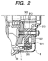
- the rectifier 5 is interposed between the frame 3b and the protecting cover 8.
- the rectifier 5 is fixedly fastened to a bearing box support 301 of the frame 3b together with the protecting cover 8.
- a smaller-diameter fin 501 having a positive electric potential, securely mounts positive rectifying elements 502 by soldering.
- Each positive rectifying element 502 has a lead which extends toward a larger-diameter fin 503.
- the larger-diameter fin 503, having a negative electric potential securely mounts negative rectifying elements 504 by soldering each negative rectifying element 504 has a lead which extends toward the smaller-diameter fin 503.
- These leads are connected to a stator lead L via a stator lead connecting terminal 505.
- the above-described arrangement constitutes an AC bridge circuit.
- B bolt 506, deriving an AC power output, is attached on the smaller-diameter fin 501 of positive electric potential..
- the positive rectifying element 502 is a diode provided at a higher-voltage side in the full-wave rectifying circuit, while the negative rectifying element 504 is a diode provided at a lower-voltage side in that rectifying circuit.
- the smaller-diameter fin 501 and the positive rectifying elements 502 are disposed inward in a radial direction and adjacent to the protecting cover 8 in an axial direction.
- the larger-diameter fin 503 and the negative rectifying elements 504 are disposed outward in the radial direction and adjacent to the frame 3b in the axial direction.
- An axial air inlet 801 is opened on the protecting cover 8 at a portion adjacent to the positive rectifying elements 502.
- a radial air inlet 802 is opened between the outer peripheral portion of the frame 3b and the protecting cover 8.
- the protecting cover 8, the smaller-diameter fin 501, the larger-diameter fine 503 and the frame 3b are separated one another by intervening clearances.
- Each clearance has an axial width equal to or less than 10 mm.
- the smaller-diameter fin 501 has a closed ring shape. This is advantageous because the heat transfer of the smaller-diameter fin 501 is improved and the heat distribution is uniformed. Accordingly, the entire body of this fin can be effectively used as a cooling medium.
- the smaller-diameter fin 501 can secure a sufficient surface area. Thus, it becomes possible to improve the cooling performance.
- the larger-diameter fin 503 is directly fastened to the frame 3b. This is advantageous because the hear of the larger-diameter fin 503 is smoothly transferred to the frame 3b. Thus, the cooling performance can be further improved.
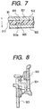
- the smaller-diameter fin 501 has a rib 510 at a radial-inner end and a rib 511 at a radial-outer end. These ribs 510 and 511 are formed by bending the radial-inner and radial-outer ends of the smaller-diameter fin 501 toward the protecting cover 8. With this arrangement, the cooling air introduced from the axial air inlet 801 is guided toward the rectifying elements 502. The flow speed of the cooling air is increased in the vicinity of the rectifying elements 502. The heat transfer coefficient is improved. The smaller-diameter fin 501 can secure a sufficient surface area. Thus, the cooling performance can be further improved.
- the smaller-diameter fin 501 functions as a flow regulating plate from its structure and disposed position.
- the introduced cooling air can flow smoothly. Fan noise can be reduced.
- the ribs 510 and 511 are bent far away from the larger-diameter fin 503 which has a different electric potential. This arrangement brings an auxiliary effect that any deposition of foreign materials or corrosion products can be avoided.
- the larger-diameter fin 503 has a rib 512 which is formed by bending a radial-inner end of the larger-diameter fin 503 toward the frame 3b.
- This arrangement is advantageous because the cooling air introduced from the radial air inlet 802 is smoothly guided by the larger-diameter fin 503 toward the cooling fan 21. Accordingly, the flow speed of the cooling air is increased in the vicinity of the rectifying elements. The heat transfer coefficient is improved.
- the larger-diameter fin 503 can secure a sufficient surface area. Thus, the cooling performance can be further improved.
- the rib 512 functions as a flow regulating plate together with the other portion of the larger-diameter fin 503. The introduced cooling air can flow smoothly. Fan noise can be reduced.
- the rib 512 is bent far away from the smaller-diameter fin 501 which has a different electric potential. This arrangement brings an auxiliary effect that any deposition of foreign materials or corrosion products can be avoided.
- a total of three terminal bases 513 are interposed between the smaller-diameter fin 501 and the larger-diameter fin 503.
- the terminal bases 513 are fixed on three supporting portions 301 extending in radial directions for supporting a bearing box 3d. Both the smaller-diameter fin 501 and the larger-diameter fin 503 are fixed to the terminal bases 513 together with the supporting portions 301. Both the smaller-diameter fin 501 and the larger-diameter fin 503 are exposed from the clearances between the terminal bases 513.
- the larger-diameter fin 503 is exposed at a portion adjacent to a radial-outer end of a cooling air inlet 803 of the frame 3b.
- the cooling air flows smoothly toward the cooling fan 21.
- the flow speed of the cooling air is increased in the vicinity of the rectifying elements 504.
- the heat transfer coefficient is improved.
- An effective cooling fin area can be secured. Thus, the cooling performance can be further improved.
- the introduced cooling air flows smoothly.
- the fan noise can be reduced as an auxiliary effect.
- each connector 513a is thin.
- a clearance 804 is provided between the smaller-diameter fin 501 and the connector 513a.
- a clearance 805 is provided between the larger-diameter fin 503 and the connector 513a.
- both of the rectifying elements 502 and 504 are mounted on the smaller-diameter fin 501 and the larger-diameter fin 503 by soldering, respectively.
- a press-fit type rectifying element 900 it is possible to secure a press-fit type rectifying element 900 to the fin, at least one of the smaller-diameter fin 501 or the larger-diameter fin 503, by press working.
- the above-described larger-diameter fin 503 formed into the ring shape can be replaced by a horseshoe-type fin.
- part of the larger-diameter fin 503 can be formed into predetermined elongated portions 521 each extending to the radial-inner end of the smaller-diameter fin 501.
- Part of the smaller-diameter fin 501 can be formed into predetermined elongated portions 520 each extending to the radial-outer end of the larger-diameter fin 503.
- the protecting cover 8 can be made of an insulating material such as nylon. This is advantageous because the durability against environments can be improved at a portion between the protecting cover 8 and the smaller-diameter fin 501. As a result, the clearance can be narrowed.
- the rectifier 5 is disposed outside the frame 3b.
- the rectifier 5 is disposed inside the frame 3b.
- the rectifier 5 is disposed between a partition plate 9 and the frame 3b.
- the rectifier 5 is integrally fixed to the bearing box support of the frame 3b together with the partition plate 9.
- the smaller-diameter fin 501 having a negative electric potential, mounts the negative rectifying elements 504 by soldering.
- Each negative rectifying element 504 has a lead which extends toward the larger-diameter fin 503.
- the larger-diameter fin 503, having a positive electric potential, mounts the positive rectifying elements 502 by soldering.
- Each positive rectifying element 502 has a lead which extends toward the smaller-diameter fin 501.
- B bolt (not shown) derives an AC power output.
- the smaller-diameter fin 501 and the negative rectifying elements 504 are disposed inward in a radial direction and adjacent to the frame 3b in an axial direction.
- the larger-diameter fin 503 and the positive rectifying elements 502 are disposed outward in the radial direction and adjacent to the partition plate 9 in the axial direction.
- An axial air inlet 801a is opened on an end wall of frame 3b at a portion adjacent to the negative rectifying elements 504.
- a radial air inlet 802a is opened on a cylindrical wall of frame 3b between the partition plate 9 and the larger-diameter fin 503.
- the partition plate 9, the smaller-diameter fin 501, the larger-diameter fine 503 and the frame 3b are separated one another by intervening clearances which introduce the cooling air.
- Each clearance has a width equal to or less than 10 mm.
- the cooling air passes the clearance at a higher speed.
- Both the smaller-diameter fin 501 and the larger-diameter fin 503 are adequately cooled by the cooling air.
- the smaller-diameter fin 501 has the rib 511 formed at a radial-outer end thereof.
- the rib 511 is bent toward the frame 3b.
- the cooling air introduced from the axial air inlet 801a can be guided to the rectifying elements by the smaller-diameter fin 501.
- This is advantageous because the flow speed of the cooling air can be increased in the vicinity of the rectifying elements.
- the heat transfer coefficient is improved.
- the smaller-diameter fin 501 can secure a sufficient surface area. Thus, the cooling performance can be further improved.
- the smaller-diameter fin 501 functions as a flow regulating plate which causes the introduced cooling air to flow smoothly. Thus, fan noise can be reduced.
- the rib 511 is bent far away from the larger-diameter fin 503 which has a different electric potential. This arrangement brings an auxiliary effect that any deposition of foreign materials or corrosion products can be avoided.
- the larger-diameter fin 503 has the rib 512 formed at a radial-inner end thereof.
- the rib 512 is bent toward the fan 21.
- This arrangement is advantageous because the cooling air introduced from the radial air inlet 802a is smoothly guided by the larger-diameter fin 503 toward the cooling fan 21. Accordingly, the flow speed of the cooling air is increased in the vicinity of the rectifying elements. The heat transfer coefficient is improved.
- the larger-diameter fin 503 can secure a sufficient surface area. Thus, the cooling performance can be further improved.
- the rib 512 are cooperative with the remaining portion of the larger-diameter fin 503 to function as a flow regulating plate which causes the introduced cooling air to flow smoothly. Fan noise can be reduced.
- the rib 512 is bent far away from the smaller-diameter fin 501 which has a different electric potential. This arrangement brings an auxiliary effect that any deposition of foreign materials or corrosion products can be avoided.
- the partition plate 9 is fixed with the rectifier 5 so as to form a parallel surface at the end of the cooling fan 21.
- the partition plate 9 functions as a shroud.
Landscapes
- Engineering & Computer Science (AREA)
- Power Engineering (AREA)
- Motor Or Generator Cooling System (AREA)
- Motor Or Generator Frames (AREA)
Applications Claiming Priority (3)
| Application Number | Priority Date | Filing Date | Title |
|---|---|---|---|
| JP26030297 | 1997-09-25 | ||
| JP26030297 | 1997-09-25 | ||
| JP260302/97 | 1997-09-25 |
Publications (3)
| Publication Number | Publication Date |
|---|---|
| EP0905863A2 true EP0905863A2 (fr) | 1999-03-31 |
| EP0905863A3 EP0905863A3 (fr) | 1999-12-22 |
| EP0905863B1 EP0905863B1 (fr) | 2002-04-17 |
Family
ID=17346155
Family Applications (1)
| Application Number | Title | Priority Date | Filing Date |
|---|---|---|---|
| EP98104310A Expired - Lifetime EP0905863B1 (fr) | 1997-09-25 | 1998-03-10 | Redresseur pour alternateur de véhicule automobile |
Country Status (4)
| Country | Link |
|---|---|
| US (2) | US5949166A (fr) |
| EP (1) | EP0905863B1 (fr) |
| CN (1) | CN1084076C (fr) |
| DE (1) | DE69804917T2 (fr) |
Cited By (2)
| Publication number | Priority date | Publication date | Assignee | Title |
|---|---|---|---|---|
| FR2827437A1 (fr) * | 2001-07-16 | 2003-01-17 | Valeo Equip Electr Moteur | Agencement de redressement de courant pour machines electriques tournantes, notamment alternateurs pour vehicule automobile |
| WO2003009452A1 (fr) * | 2001-07-16 | 2003-01-30 | Valeo Equipements Electriques Moteur | Agencement de redressement de courant pour machines electriques tournantes, notamment alternateur pour vehicule automobile |
Families Citing this family (41)
| Publication number | Priority date | Publication date | Assignee | Title |
|---|---|---|---|---|
| US5949166A (en) * | 1997-09-25 | 1999-09-07 | Denso Corporation | Rectifying apparatus for an automotive AC generator |
| DE19828518A1 (de) * | 1998-06-26 | 1999-12-30 | Bosch Gmbh Robert | Elektrische Maschine, vorzugsweise Drehstromgenerator mit Gleichrichter-Baueinheit |
| JP3374776B2 (ja) * | 1999-02-05 | 2003-02-10 | 株式会社デンソー | 車両用交流発電機 |
| US6252320B1 (en) * | 1999-05-24 | 2001-06-26 | Unit Parts Company | Alternator system |
| JP2002084723A (ja) * | 2000-09-01 | 2002-03-22 | Mitsubishi Electric Corp | 車両用交流発電機 |
| JP3949369B2 (ja) * | 2000-10-20 | 2007-07-25 | 三菱電機株式会社 | 車両用交流発電機 |
| JP4360027B2 (ja) * | 2000-11-06 | 2009-11-11 | 株式会社デンソー | 車両用交流発電機 |
| JP3944357B2 (ja) * | 2001-02-08 | 2007-07-11 | 三菱電機株式会社 | 車両用交流発電機 |
| DE10110128B4 (de) * | 2001-03-02 | 2015-07-02 | Robert Bosch Gmbh | Elektrische Maschine |
| JP3775235B2 (ja) * | 2001-03-29 | 2006-05-17 | 株式会社デンソー | 車両用交流発電機 |
| JP3733313B2 (ja) * | 2001-10-26 | 2006-01-11 | 住友電装株式会社 | 車両用薄型ブラシレスモータの集中配電部材 |
| DE10154866A1 (de) * | 2001-11-08 | 2003-05-28 | Bosch Gmbh Robert | Elektrische Maschine, vorzugsweise Drehstromgenerator für Kraftfahrzeuge |
| JP3690348B2 (ja) * | 2002-01-08 | 2005-08-31 | 株式会社日立製作所 | 自動車用交流発電機 |
| JP3750851B2 (ja) * | 2002-01-18 | 2006-03-01 | 株式会社デンソー | 車両用交流発電機 |
| JP3823856B2 (ja) * | 2002-03-19 | 2006-09-20 | 株式会社デンソー | 車両用交流発電機の整流装置 |
| JP4007229B2 (ja) * | 2002-08-30 | 2007-11-14 | 株式会社デンソー | 車両用交流発電機 |
| JP2004153891A (ja) * | 2002-10-29 | 2004-05-27 | Mitsubishi Electric Corp | 回転電機 |
| US6825586B2 (en) * | 2002-10-29 | 2004-11-30 | Remy, Inc. | One piece stator lead and terminal insulator |
| JP4089421B2 (ja) * | 2002-12-19 | 2008-05-28 | 株式会社デンソー | 車両用交流発電機 |
| US6828703B2 (en) * | 2003-03-06 | 2004-12-07 | Visteon Global Technologies, Inc. | Diode interconnection in an alternator rectifier |
| KR100608925B1 (ko) * | 2003-03-18 | 2006-08-03 | 가부시키가이샤 덴소 | 차량용 교류발전기 |
| JP3966212B2 (ja) * | 2003-04-08 | 2007-08-29 | 株式会社デンソー | 車両用交流発電機 |
| JP3974560B2 (ja) * | 2003-06-19 | 2007-09-12 | 三菱電機株式会社 | 回転電機 |
| JP4111162B2 (ja) * | 2004-03-29 | 2008-07-02 | 株式会社デンソー | 車両用交流発電機 |
| US7633198B2 (en) * | 2005-03-16 | 2009-12-15 | Robert Ernest Kirkman | 50 DN alternator stator terminal insulator apparatus |
| US20060232151A1 (en) * | 2005-04-15 | 2006-10-19 | Dubois Randy P | Slip ring end housing for a dual rectifier alternator |
| JP4549924B2 (ja) * | 2005-05-20 | 2010-09-22 | 三菱電機株式会社 | 車両用回転電機 |
| JP2006352946A (ja) * | 2005-06-13 | 2006-12-28 | Denso Corp | 車両用回転電機 |
| JP4994621B2 (ja) * | 2005-08-23 | 2012-08-08 | 株式会社デンソー | 車両用交流発電機の電圧制御装置 |
| JP4497062B2 (ja) * | 2005-08-29 | 2010-07-07 | 株式会社デンソー | 車両用交流発電機 |
| JP4402057B2 (ja) * | 2006-02-21 | 2010-01-20 | 三菱電機株式会社 | 制御装置一体型回転電機 |
| JP4797779B2 (ja) * | 2006-04-27 | 2011-10-19 | 株式会社デンソー | 車両用交流発電機 |
| JP2007330018A (ja) * | 2006-06-07 | 2007-12-20 | Denso Corp | タンデム型交流発電機の回転子 |
| JP4470927B2 (ja) * | 2006-09-07 | 2010-06-02 | 株式会社デンソー | 車両用交流発電機 |
| JP4471126B2 (ja) * | 2006-09-07 | 2010-06-02 | 株式会社デンソー | 車両用交流発電機 |
| DE102008002638A1 (de) * | 2008-06-25 | 2009-12-31 | Robert Bosch Gmbh | Elektrische Maschine |
| JP5401367B2 (ja) | 2010-03-12 | 2014-01-29 | 日立オートモティブシステムズ株式会社 | 車両用交流発電機 |
| EP2787608B1 (fr) * | 2011-11-30 | 2016-11-30 | Mitsubishi Electric Corporation | Machine électrique tournante pour véhicule |
| US9312742B2 (en) | 2013-03-01 | 2016-04-12 | Hamilton Sundstrand Corporation | Connector and spring assembly for a generator |
| JP2014220901A (ja) * | 2013-05-08 | 2014-11-20 | 三菱電機株式会社 | 永久磁石埋込型回転電機 |
| US9661789B2 (en) * | 2014-01-22 | 2017-05-23 | Remy Technologies, Llc | Cooling air routing for electronics heat removal |
Citations (3)
| Publication number | Priority date | Publication date | Assignee | Title |
|---|---|---|---|---|
| BE677569A (fr) * | 1965-04-08 | 1966-08-01 | ||
| JPH07336945A (ja) * | 1994-06-10 | 1995-12-22 | Sawafuji Electric Co Ltd | オルタネータ |
| JPH09201009A (ja) * | 1996-01-16 | 1997-07-31 | Denso Corp | 交流発電機 |
Family Cites Families (20)
| Publication number | Priority date | Publication date | Assignee | Title |
|---|---|---|---|---|
| DE1261229B (de) * | 1963-12-13 | 1968-02-15 | Bosch Gmbh Robert | Selbsterregter Drehstromgenerator, insbesondere fuer Fahrzeuglichtanlagen |
| US3970881A (en) * | 1974-03-12 | 1976-07-20 | Nippondenso Co., Ltd. | Rectifier assembly |
| JPS5273410U (fr) * | 1975-11-28 | 1977-06-01 | ||
| JPH0119584Y2 (fr) * | 1980-05-09 | 1989-06-06 | ||
| US4588911A (en) * | 1984-12-14 | 1986-05-13 | General Motors Corporation | Alternating current generator rotor and fan |
| US4604538A (en) * | 1985-02-19 | 1986-08-05 | General Motors Corporation | Air cooling for diode-rectified alternating current generators |
| US4606000A (en) * | 1985-03-27 | 1986-08-12 | General Motors Corporation | Bridge rectifier |
| DE3728081A1 (de) * | 1987-08-22 | 1989-03-02 | Bosch Gmbh Robert | Gleichrichterlagereinrichtung |
| JPH0736687A (ja) * | 1993-07-16 | 1995-02-07 | Hitachi Ltd | 新運用プログラムの作成方法 |
| JP3514319B2 (ja) * | 1993-07-26 | 2004-03-31 | 株式会社デンソー | 回転電機 |
| US5640062A (en) * | 1994-03-10 | 1997-06-17 | Ford Motor Company | Alternator with internal rectifier bridge assembly |
| JP3518018B2 (ja) * | 1994-03-11 | 2004-04-12 | 株式会社デンソー | 車両用交流発電機 |
| US5473208A (en) * | 1994-06-08 | 1995-12-05 | Stihi; Edward | Cooling structure for alternator rectifier |
| JP3458530B2 (ja) * | 1995-06-02 | 2003-10-20 | 株式会社デンソー | 交流発電機の整流電圧調整装置 |
| JP3342987B2 (ja) * | 1995-06-28 | 2002-11-11 | 三菱電機株式会社 | 車両用交流発電機 |
| US5757096A (en) * | 1995-09-12 | 1998-05-26 | Dubois; Randy P. | Alternator cooling device |
| JP3543881B2 (ja) * | 1995-11-08 | 2004-07-21 | 株式会社デンソー | 交流発電機 |
| JPH1036945A (ja) * | 1996-07-19 | 1998-02-10 | Nippon Steel Corp | ねじ込み性に優れた高耐銹性マルテンサイト系ステンレス製ドリリングタッピンねじ及びその焼入方法 |
| US5838544A (en) * | 1997-05-13 | 1998-11-17 | Mobiletron Electronics Co., Ltd. | Heat dissipating structure for rectifiers of car alternators |
| US5949166A (en) * | 1997-09-25 | 1999-09-07 | Denso Corporation | Rectifying apparatus for an automotive AC generator |
-
1998
- 1998-03-06 US US09/035,813 patent/US5949166A/en not_active Expired - Lifetime
- 1998-03-10 DE DE69804917T patent/DE69804917T2/de not_active Expired - Lifetime
- 1998-03-10 EP EP98104310A patent/EP0905863B1/fr not_active Expired - Lifetime
- 1998-03-25 CN CN98114828A patent/CN1084076C/zh not_active Expired - Lifetime
-
1999
- 1999-07-09 US US09/349,163 patent/US6184602B1/en not_active Expired - Lifetime
Patent Citations (3)
| Publication number | Priority date | Publication date | Assignee | Title |
|---|---|---|---|---|
| BE677569A (fr) * | 1965-04-08 | 1966-08-01 | ||
| JPH07336945A (ja) * | 1994-06-10 | 1995-12-22 | Sawafuji Electric Co Ltd | オルタネータ |
| JPH09201009A (ja) * | 1996-01-16 | 1997-07-31 | Denso Corp | 交流発電機 |
Non-Patent Citations (2)
| Title |
|---|
| PATENT ABSTRACTS OF JAPAN vol. 1996, no. 04, 30 April 1996 (1996-04-30) & JP 07 336945 A (SAWAFUJI ELECTRIC CO LTD), 22 December 1995 (1995-12-22) * |
| PATENT ABSTRACTS OF JAPAN vol. 1997, no. 11, 28 November 1997 (1997-11-28) & JP 09 201009 A (DENSO CORP), 31 July 1997 (1997-07-31) * |
Cited By (4)
| Publication number | Priority date | Publication date | Assignee | Title |
|---|---|---|---|---|
| FR2827437A1 (fr) * | 2001-07-16 | 2003-01-17 | Valeo Equip Electr Moteur | Agencement de redressement de courant pour machines electriques tournantes, notamment alternateurs pour vehicule automobile |
| WO2003009452A1 (fr) * | 2001-07-16 | 2003-01-30 | Valeo Equipements Electriques Moteur | Agencement de redressement de courant pour machines electriques tournantes, notamment alternateur pour vehicule automobile |
| US7019424B2 (en) | 2001-07-16 | 2006-03-28 | Valeo Equipements Electriques Moteur | Current rectifier assembly for rotating electrical machines, in particular motor vehicle alternator |
| EP2843811A1 (fr) * | 2001-07-16 | 2015-03-04 | Valeo Equipements Electriques Moteur | Machine électrique comprenant un agencement de redressement de courant, notamment alternateur pour véhicule automobile |
Also Published As
| Publication number | Publication date |
|---|---|
| US6184602B1 (en) | 2001-02-06 |
| DE69804917T2 (de) | 2002-12-12 |
| DE69804917D1 (de) | 2002-05-23 |
| US5949166A (en) | 1999-09-07 |
| CN1212493A (zh) | 1999-03-31 |
| EP0905863B1 (fr) | 2002-04-17 |
| EP0905863A3 (fr) | 1999-12-22 |
| CN1084076C (zh) | 2002-05-01 |
Similar Documents
| Publication | Publication Date | Title |
|---|---|---|
| US5949166A (en) | Rectifying apparatus for an automotive AC generator | |
| US6426575B1 (en) | AC generator for an automotive vehicle with enhanced cooling of internal elements | |
| US7417344B2 (en) | Electronic package for electrical machine | |
| JP3536472B2 (ja) | 交流発電機 | |
| JP4007229B2 (ja) | 車両用交流発電機 | |
| US6809443B2 (en) | Alternator for an automotive vehicle | |
| US6664674B2 (en) | Cooling structure of vehicle AC generator | |
| JP3750851B2 (ja) | 車両用交流発電機 | |
| US6150741A (en) | Alternating current generator for vehicles having improved output terminal fixing structure | |
| KR20000069462A (ko) | 전기장치, 특히 정류기 조립소자가 있는 교류발전기 | |
| US7741739B2 (en) | Automotive alternator | |
| JPH09140099A (ja) | 発電機 | |
| KR20020030698A (ko) | 차량용 교류발전기 | |
| JP2000253625A (ja) | 車両用交流発電機 | |
| KR20040082335A (ko) | 차량용 교류발전기 | |
| JP3438577B2 (ja) | 車両用交流発電機 | |
| US7569956B2 (en) | Automotive tandem alternator having reduced axial length and improved structure for effectively dissipating heat generated by rectifiers | |
| US7339296B2 (en) | Ac generator having built-in voltage regulator | |
| JP3815059B2 (ja) | 車両用交流発電機 | |
| US6933635B2 (en) | Automotive alternator | |
| JPH0426346A (ja) | 車両用交流発電機における整流装置 | |
| JPH11164518A (ja) | 車両用交流発電機 | |
| JP3707477B2 (ja) | 車両用交流発電機 | |
| JP4126813B2 (ja) | 車両用交流発電機 | |
| JPH03178539A (ja) | 車両用交流発電機 |
Legal Events
| Date | Code | Title | Description |
|---|---|---|---|
| PUAI | Public reference made under article 153(3) epc to a published international application that has entered the european phase |
Free format text: ORIGINAL CODE: 0009012 |
|
| AK | Designated contracting states |
Kind code of ref document: A2 Designated state(s): DE FR GB |
|
| AX | Request for extension of the european patent |
Free format text: AL;LT;LV;MK;RO;SI |
|
| PUAL | Search report despatched |
Free format text: ORIGINAL CODE: 0009013 |
|
| AK | Designated contracting states |
Kind code of ref document: A3 Designated state(s): AT BE CH DE DK ES FI FR GB GR IE IT LI LU MC NL PT SE |
|
| AX | Request for extension of the european patent |
Free format text: AL;LT;LV;MK;RO;SI |
|
| 17P | Request for examination filed |
Effective date: 20000407 |
|
| AKX | Designation fees paid |
Free format text: DE FR GB |
|
| GRAG | Despatch of communication of intention to grant |
Free format text: ORIGINAL CODE: EPIDOS AGRA |
|
| 17Q | First examination report despatched |
Effective date: 20011002 |
|
| REG | Reference to a national code |
Ref country code: GB Ref legal event code: IF02 |
|
| GRAG | Despatch of communication of intention to grant |
Free format text: ORIGINAL CODE: EPIDOS AGRA |
|
| GRAH | Despatch of communication of intention to grant a patent |
Free format text: ORIGINAL CODE: EPIDOS IGRA |
|
| GRAH | Despatch of communication of intention to grant a patent |
Free format text: ORIGINAL CODE: EPIDOS IGRA |
|
| GRAA | (expected) grant |
Free format text: ORIGINAL CODE: 0009210 |
|
| AK | Designated contracting states |
Kind code of ref document: B1 Designated state(s): DE FR GB |
|
| REF | Corresponds to: |
Ref document number: 69804917 Country of ref document: DE Date of ref document: 20020523 |
|
| ET | Fr: translation filed | ||
| PLBE | No opposition filed within time limit |
Free format text: ORIGINAL CODE: 0009261 |
|
| STAA | Information on the status of an ep patent application or granted ep patent |
Free format text: STATUS: NO OPPOSITION FILED WITHIN TIME LIMIT |
|
| 26N | No opposition filed |
Effective date: 20030120 |
|
| REG | Reference to a national code |
Ref country code: FR Ref legal event code: PLFP Year of fee payment: 19 |
|
| REG | Reference to a national code |
Ref country code: FR Ref legal event code: PLFP Year of fee payment: 20 |
|
| PGFP | Annual fee paid to national office [announced via postgrant information from national office to epo] |
Ref country code: DE Payment date: 20170322 Year of fee payment: 20 Ref country code: FR Payment date: 20170322 Year of fee payment: 20 |
|
| PGFP | Annual fee paid to national office [announced via postgrant information from national office to epo] |
Ref country code: GB Payment date: 20170322 Year of fee payment: 20 |
|
| REG | Reference to a national code |
Ref country code: DE Ref legal event code: R071 Ref document number: 69804917 Country of ref document: DE |
|
| REG | Reference to a national code |
Ref country code: GB Ref legal event code: PE20 Expiry date: 20180309 |
|
| PG25 | Lapsed in a contracting state [announced via postgrant information from national office to epo] |
Ref country code: GB Free format text: LAPSE BECAUSE OF EXPIRATION OF PROTECTION Effective date: 20180309 |