US5838544A - Heat dissipating structure for rectifiers of car alternators - Google Patents
Heat dissipating structure for rectifiers of car alternators Download PDFInfo
- Publication number
- US5838544A US5838544A US08/855,171 US85517197A US5838544A US 5838544 A US5838544 A US 5838544A US 85517197 A US85517197 A US 85517197A US 5838544 A US5838544 A US 5838544A
- Authority
- US
- United States
- Prior art keywords
- heat dissipating
- heat
- rectifying elements
- plate
- assembly
- Prior art date
- Legal status (The legal status is an assumption and is not a legal conclusion. Google has not performed a legal analysis and makes no representation as to the accuracy of the status listed.)
- Expired - Fee Related
Links
Images

Classifications
-
- H—ELECTRICITY
- H01—ELECTRIC ELEMENTS
- H01L—SEMICONDUCTOR DEVICES NOT COVERED BY CLASS H10
- H01L25/00—Assemblies consisting of a plurality of individual semiconductor or other solid state devices ; Multistep manufacturing processes thereof
- H01L25/03—Assemblies consisting of a plurality of individual semiconductor or other solid state devices ; Multistep manufacturing processes thereof all the devices being of a type provided for in the same subgroup of groups H01L27/00 - H01L33/00, or in a single subclass of H10K, H10N, e.g. assemblies of rectifier diodes
- H01L25/10—Assemblies consisting of a plurality of individual semiconductor or other solid state devices ; Multistep manufacturing processes thereof all the devices being of a type provided for in the same subgroup of groups H01L27/00 - H01L33/00, or in a single subclass of H10K, H10N, e.g. assemblies of rectifier diodes the devices having separate containers
- H01L25/11—Assemblies consisting of a plurality of individual semiconductor or other solid state devices ; Multistep manufacturing processes thereof all the devices being of a type provided for in the same subgroup of groups H01L27/00 - H01L33/00, or in a single subclass of H10K, H10N, e.g. assemblies of rectifier diodes the devices having separate containers the devices being of a type provided for in group H01L29/00
- H01L25/112—Mixed assemblies
-
- H—ELECTRICITY
- H02—GENERATION; CONVERSION OR DISTRIBUTION OF ELECTRIC POWER
- H02K—DYNAMO-ELECTRIC MACHINES
- H02K11/00—Structural association of dynamo-electric machines with electric components or with devices for shielding, monitoring or protection
- H02K11/04—Structural association of dynamo-electric machines with electric components or with devices for shielding, monitoring or protection for rectification
- H02K11/049—Rectifiers associated with stationary parts, e.g. stator cores
- H02K11/05—Rectifiers associated with casings, enclosures or brackets
-
- H—ELECTRICITY
- H01—ELECTRIC ELEMENTS
- H01L—SEMICONDUCTOR DEVICES NOT COVERED BY CLASS H10
- H01L2924/00—Indexing scheme for arrangements or methods for connecting or disconnecting semiconductor or solid-state bodies as covered by H01L24/00
- H01L2924/0001—Technical content checked by a classifier
- H01L2924/0002—Not covered by any one of groups H01L24/00, H01L24/00 and H01L2224/00
Definitions
- This invention relates generally to an improved heat dissipation structure for rectifiers of car alternators, and more particularly to a structure that may reduce the size and weight of heat dissipating materials consumed by the rectifier and achieve effective heat dissipation.
- Cars' electricity supply depends upon their alternators as well as their batteries. Electric power generated by the alternator may be accumulated in the battery so that the battery will not easily run out of electric power. If the alternator cannot generate sufficient electric power, the car may run out of electricity. The electricity generating effects of the alternator cannot therefore be overlooked.
- alternators As alternators generate alternating currents, they must be rectified into direct currents before they can be used by the car and the battery. Therefore, a bridge type rectifier circuit is disposed at an output of the alternator. However, since there is extremely high working temperature around the car engine, the electronic structure of the rectifier will be affected by high temperature so that the electricity generating and rectifying effects are lowered. Besides, after the rectifying circuit has worked for a period of time, its internal temperature will also rise, so that power supply is abnormal. Therefore, alternators must be equipped with heat dissipation structures to ensure their normal operation.
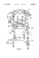
- FIG. 1 shows a conventional heat dissipation structure for car alternators. It essentially comprises an upper cover 100 covering a rectifier assembly 400 disposed on a heat dissipating plate 300.
- the rectifier assembly 400 is comprised of a plurality of rectifying elements 401, 402, 403, . . . , a plurality of terminals 411, 412, 413, . . . , and a dissipating drum 420 for receiving the rectifying elements.
- the rectifying elements are generally rectifying diodes, having one side in contact with the terminals.
- the respective terminals pass have a portion passing through the upper cover 100.
- the upper cover 100 has a rectifier circuit formed by electrically conductive lapping plates 101.
- the heat dissipating drum 420 is a thermally conductive metal housing.
- a pad 421 is disposed below the heat dissipating drum 420, and the heat dissipating plate 300 is provided below the pad 421.
- the heat generated by the rectifying elements during work or the ambient heat may pass from the dissipating drum 420 through the pad 421 to the peripheral walls of the heat dissipating plate 300, and to the atmosphere.
- the dissipating drum 420 has to cover a large area in order to absorb all the heat.
- a large-size dissipating drum will be very bulky and space-occupying, and will be very inconvenient to install. Besides, it will increase the weight of the alternator and hence the weight of the car, which will result in greater consumption of power. In addition, the the pad 421 will not be able to transmit the heat, and a cooling fan will become necessary, which is not advantageous to the alternator itself.
- This invention relates generally to an improved heat dissipation structure for rectifiers of car alternators, and more particularly to a structure that may reduce the size and weight of heat dissipating materials consumed by the rectifier and achieve effective heat dissipation.
- the ceramic heat dissipating substrate is itself a good heat conductor which may quickly distribute heat to the heat dissipating plate which is made of copper.
- the heat dissipating plate in turn dissipates the heat to the housing of the alternator.
- the heat dissipating structure of the invention is compact in size and light in weight. Besides, heat dissipating effects is excellent, and assembly easy. There is no need to provide any cooling fans, and the engine power consumption may be reduced.
- FIG. 1 is an elevational exploded view of a conventional heat dissipating structure for rectifiers of car alternators
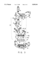
- FIG. 2 is an elevational view of the improved heat dissipating structure for rectifiers of car alternators
- FIG. 3 is an elevational exploded view of the improved heat dissipating structure for rectifiers of car alternators.
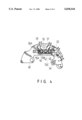
- FIG. 4 is a sectional view taken along line 4--4 of FIG. 2.
- the improved heat dissipating structure for rectifiers of car alternators of the present invention essentially comprises an upper cover 10 accommodating a rectifier assembly 20 disposed on a heat dissipating plate 30.
- the rectifier assembly 20 is comprised of a plurality of rectifying elements 40, 41, 42, 43, . . . , a capacitor 90, a plurality of terminals 50, 51, 53, and a heat conductive assembly 60 for receiving the rectifying elements.
- the rectifying elements are rectifying diodes.
- the rectifying elements are connected to the two pins of each corresponding terminal in pairs of two to form the rectifier circuit as shown in FIG. 4.
- the heat conductive assembly 60 on which the rectifying elements are joined to the terminals is comprised of a heat conductive plate 70 and a ceramic heat dissipating substrate 80.
- Several copper plated portions 70A, 70B, 70C are formed on the heat conductive plate 70, and the rectifying elements are soldered to the corresponding copper plated portions.
- the ceramic heat dissipating substrate 80 is disposed between the heat conductive plate 70 and the heat dissipating plate 30.
- a copper plated portion 70D is formed at an edge of the heat conductive plate 70 to which a pin of the capacitor 90 may be soldered. The other pin of the capacitor 90 is soldered to a corresponding copper plated portion 30A on the heat dissipating plate 30.
- the capacitor 90 is therefore secured between the heat conductive plate 70 and the heat dissipating plate 30.
- a pad 31 is disposed at one end of that side of the heat dissipating plate 30 facing the bottom side of the upper cover 10.
- the pad 31 has an elongate terminal 32 disposed thereon.
- the elongate terminal 32 has a screw hole 33 for passage of a screw rod 34.
- the screw rod 34 extends through a hollow in the upper cover 10 for locking to an alternator (not shown).
- a through hole 35 is further provided at a suitable position of the heat dissipating plate 30.
- a post 11 projects from the bottom side of the upper cover 10 at a corresponding position for matching the through hole 35 of the heat dissipating plate 30.
- the post 11 When the upper cover 10 and the heat dissipating plate 30 are coupled, the post 11 will insert into the through hole 35, and the rectifier assembly 20 is held between the upper cover 10 and the heat dissipating plate 30.
- the ceramic heat dissipating substrate 80 In use, due to the excellent heat dissipating effects of the ceramic heat dissipating substrate 80, the high heat generated by the rectifying elements and the surrounding heat may be considerably absorbed. Because of its exceptionally good heat dissipating effects, the ceramic heat dissipating substrate 80 may be compactly made, so that the size and weight of the overall heat dissipating structure may be greatly reduced.
Landscapes
- Engineering & Computer Science (AREA)
- Power Engineering (AREA)
- Microelectronics & Electronic Packaging (AREA)
- Physics & Mathematics (AREA)
- Condensed Matter Physics & Semiconductors (AREA)
- General Physics & Mathematics (AREA)
- Computer Hardware Design (AREA)
- Cooling Or The Like Of Electrical Apparatus (AREA)
- Motor Or Generator Cooling System (AREA)
- Control Of Eletrric Generators (AREA)
Abstract
A heat dissipating structure for rectifiers of car alternators includes an upper cover, a rectifier assembly disposed under the upper cover, and a heat dissipating plate disposed below the rectifier assembly. The rectifier assembly is comprised of a plurality of rectifying elements and terminals, and a heat conductive assembly for receiving the rectifying elements. One side of the respective rectifying elements are connected to the terminals to constitute a rectifier circuit. The other side of the respective rectifying elements are connected to the heat conductive assembly, which is in turn connected to the heat dissipating plate. The heat conductive assembly is comprised of a heat conductive plate to which the rectifying elements may adhere, and a ceramic heat dissipating substrate disposed between the heat conductive plate and the heat dissipating plate. The ceramic heat dissipating substrate may efficiently dissipate heat and is compact in size, so that the overall size and weight of the heat dissipating structure may be reduced in size and weight.
Description
1. Field of the Invention
This invention relates generally to an improved heat dissipation structure for rectifiers of car alternators, and more particularly to a structure that may reduce the size and weight of heat dissipating materials consumed by the rectifier and achieve effective heat dissipation.
2. Description of the Prior Art
Cars' electricity supply depends upon their alternators as well as their batteries. Electric power generated by the alternator may be accumulated in the battery so that the battery will not easily run out of electric power. If the alternator cannot generate sufficient electric power, the car may run out of electricity. The electricity generating effects of the alternator cannot therefore be overlooked.
As alternators generate alternating currents, they must be rectified into direct currents before they can be used by the car and the battery. Therefore, a bridge type rectifier circuit is disposed at an output of the alternator. However, since there is extremely high working temperature around the car engine, the electronic structure of the rectifier will be affected by high temperature so that the electricity generating and rectifying effects are lowered. Besides, after the rectifying circuit has worked for a period of time, its internal temperature will also rise, so that power supply is abnormal. Therefore, alternators must be equipped with heat dissipation structures to ensure their normal operation.
FIG. 1 shows a conventional heat dissipation structure for car alternators. It essentially comprises an upper cover 100 covering a rectifier assembly 400 disposed on a heat dissipating plate 300. The rectifier assembly 400 is comprised of a plurality of rectifying elements 401, 402, 403, . . . , a plurality of terminals 411, 412, 413, . . . , and a dissipating drum 420 for receiving the rectifying elements. The rectifying elements are generally rectifying diodes, having one side in contact with the terminals. The respective terminals pass have a portion passing through the upper cover 100. The upper cover 100 has a rectifier circuit formed by electrically conductive lapping plates 101. The heat dissipating drum 420 is a thermally conductive metal housing. A pad 421 is disposed below the heat dissipating drum 420, and the heat dissipating plate 300 is provided below the pad 421. In this way, the heat generated by the rectifying elements during work or the ambient heat may pass from the dissipating drum 420 through the pad 421 to the peripheral walls of the heat dissipating plate 300, and to the atmosphere. In this structure, however excellent the heat dissipation effects of the specially selected metal material of the dissipating drum 420 are, the dissipating drum 420 has to cover a large area in order to absorb all the heat. A large-size dissipating drum will be very bulky and space-occupying, and will be very inconvenient to install. Besides, it will increase the weight of the alternator and hence the weight of the car, which will result in greater consumption of power. In addition, the the pad 421 will not be able to transmit the heat, and a cooling fan will become necessary, which is not advantageous to the alternator itself.
This invention relates generally to an improved heat dissipation structure for rectifiers of car alternators, and more particularly to a structure that may reduce the size and weight of heat dissipating materials consumed by the rectifier and achieve effective heat dissipation.
It is a primary object of the present invention to provide an improved heat dissipating structure for rectifiers of car alternators, in which rectifying elements are connected to a heat conductive assembly, the heat conductive assembly comprising a heat conductive plate to which the rectifying elements may adhere, and a ceramic heat dissipating substrate disposed between the heat conductive plate and a heat dissipating plate. The ceramic heat dissipating substrate is itself a good heat conductor which may quickly distribute heat to the heat dissipating plate which is made of copper. The heat dissipating plate in turn dissipates the heat to the housing of the alternator. Compared to the prior art, the heat dissipating structure of the invention is compact in size and light in weight. Besides, heat dissipating effects is excellent, and assembly easy. There is no need to provide any cooling fans, and the engine power consumption may be reduced.
The invention is further described hereafter, by way of example only, with reference to the accompanying drawings, in which:
FIG. 1 is an elevational exploded view of a conventional heat dissipating structure for rectifiers of car alternators;
FIG. 2 is an elevational view of the improved heat dissipating structure for rectifiers of car alternators;
FIG. 3 is an elevational exploded view of the improved heat dissipating structure for rectifiers of car alternators; and
FIG. 4 is a sectional view taken along line 4--4 of FIG. 2.
For the purpose of promoting an understanding of the principles of the invention, reference will now be made to the embodiment illustrated in the drawings. Specific language will be used to describe same. It will, nevertheless, be understood that no limitation of the scope of the invention is thereby intended, such alterations and further modifications in the illustrated device, and such further applications of the principles of the invention as illustrated herein being contemplated as would normally occur to one skilled in the art to which the invention relates.
With reference to FIGS. 2 and 3, the improved heat dissipating structure for rectifiers of car alternators of the present invention essentially comprises an upper cover 10 accommodating a rectifier assembly 20 disposed on a heat dissipating plate 30. The rectifier assembly 20 is comprised of a plurality of rectifying elements 40, 41, 42, 43, . . . , a capacitor 90, a plurality of terminals 50, 51, 53, and a heat conductive assembly 60 for receiving the rectifying elements. The rectifying elements are rectifying diodes. The rectifying elements are connected to the two pins of each corresponding terminal in pairs of two to form the rectifier circuit as shown in FIG. 4. The heat conductive assembly 60 on which the rectifying elements are joined to the terminals is comprised of a heat conductive plate 70 and a ceramic heat dissipating substrate 80. Several copper plated portions 70A, 70B, 70C are formed on the heat conductive plate 70, and the rectifying elements are soldered to the corresponding copper plated portions. The ceramic heat dissipating substrate 80 is disposed between the heat conductive plate 70 and the heat dissipating plate 30. Additionally, a copper plated portion 70D is formed at an edge of the heat conductive plate 70 to which a pin of the capacitor 90 may be soldered. The other pin of the capacitor 90 is soldered to a corresponding copper plated portion 30A on the heat dissipating plate 30. The capacitor 90 is therefore secured between the heat conductive plate 70 and the heat dissipating plate 30. A pad 31 is disposed at one end of that side of the heat dissipating plate 30 facing the bottom side of the upper cover 10. The pad 31 has an elongate terminal 32 disposed thereon. The elongate terminal 32 has a screw hole 33 for passage of a screw rod 34. The screw rod 34 extends through a hollow in the upper cover 10 for locking to an alternator (not shown). A through hole 35 is further provided at a suitable position of the heat dissipating plate 30. A post 11 projects from the bottom side of the upper cover 10 at a corresponding position for matching the through hole 35 of the heat dissipating plate 30. When the upper cover 10 and the heat dissipating plate 30 are coupled, the post 11 will insert into the through hole 35, and the rectifier assembly 20 is held between the upper cover 10 and the heat dissipating plate 30. In use, due to the excellent heat dissipating effects of the ceramic heat dissipating substrate 80, the high heat generated by the rectifying elements and the surrounding heat may be considerably absorbed. Because of its exceptionally good heat dissipating effects, the ceramic heat dissipating substrate 80 may be compactly made, so that the size and weight of the overall heat dissipating structure may be greatly reduced.
It will be understood that each of the elements described above, or two or more together may also find a useful application in other types of methods differing from the type described above.
While certain novel features of this invention have been shown and described and are pointed out in the annexed claim, it is not intended to be limited to the details above, since it will be understood that various omissions, modifications, substitutions and changes in the forms and details of the device illustrated and in its operation can be made by those skilled in the art without departing in any way from the spirit of the present invention.
Without further analysis, the foregoing will so fully reveal the gist of the present invention that others can, by applying current knowledge, readily adapt it for various applications without omitting features that, from the standpoint of prior art, fairly constitute essential characteristics of the generic or specific aspects of this invention.
Claims (3)
1. A heat dissipating structure for rectifiers of car alternators comprising:
an upper cover;
a rectifier assembly, disposed below said upper cover, and being comprised of a plurality of rectifying elements and terminals, and a heat conductive assembly for receiving said rectifying elements, said conductive assembly having a heat conductive plate to which said rectifying elements may be soldered, and a ceramic heat dissipating substrate; and
a heat dissipating plate; wherein said rectifying elements have one side connected to corresponding terminals to form a rectifier circuit;
said rectifying elements have another side connected to said heat conductive assembly, which is in turn connected to said heat dissipating plate; and said ceramic heat dissipating substrate is disposed between said heat conductive plate and said heat dissipating plate.
2. The heat dissipating structure for rectifiers of car alternators as claimed in claim 1, wherein said rectifying elements are connected to a respective pair of pins of each of said terminals in pairs of two.
3. The heat dissipating structure for rectifiers of car alternators as claimed in claim 1, wherein said heat conductive plate has a plurality of copper plated portions formed thereon to which said rectifying elements may be soldered.
Priority Applications (3)
| Application Number | Priority Date | Filing Date | Title |
|---|---|---|---|
| US08/855,171 US5838544A (en) | 1997-05-13 | 1997-05-13 | Heat dissipating structure for rectifiers of car alternators |
| DE29805118U DE29805118U1 (en) | 1997-05-13 | 1998-03-20 | Improved cooler structure of a regulator for automotive alternators |
| GB9805881A GB2335513B (en) | 1997-05-13 | 1998-03-20 | Improved radiator structure of a regulator for car alternators |
Applications Claiming Priority (3)
| Application Number | Priority Date | Filing Date | Title |
|---|---|---|---|
| US08/855,171 US5838544A (en) | 1997-05-13 | 1997-05-13 | Heat dissipating structure for rectifiers of car alternators |
| DE29805118U DE29805118U1 (en) | 1997-05-13 | 1998-03-20 | Improved cooler structure of a regulator for automotive alternators |
| GB9805881A GB2335513B (en) | 1997-05-13 | 1998-03-20 | Improved radiator structure of a regulator for car alternators |
Publications (1)
| Publication Number | Publication Date |
|---|---|
| US5838544A true US5838544A (en) | 1998-11-17 |
Family
ID=27220086
Family Applications (1)
| Application Number | Title | Priority Date | Filing Date |
|---|---|---|---|
| US08/855,171 Expired - Fee Related US5838544A (en) | 1997-05-13 | 1997-05-13 | Heat dissipating structure for rectifiers of car alternators |
Country Status (3)
| Country | Link |
|---|---|
| US (1) | US5838544A (en) |
| DE (1) | DE29805118U1 (en) |
| GB (1) | GB2335513B (en) |
Cited By (9)
| Publication number | Priority date | Publication date | Assignee | Title |
|---|---|---|---|---|
| US5949166A (en) * | 1997-09-25 | 1999-09-07 | Denso Corporation | Rectifying apparatus for an automotive AC generator |
| US5991184A (en) * | 1999-03-02 | 1999-11-23 | Transpo Electronics, Inc. | Vehicular extended thermal cycle minimal part robust rectifier assembly |
| US6271607B1 (en) * | 1998-06-26 | 2001-08-07 | Valeo Equipments Electriques Moteur | Sub-assemblies with electronic components, for motor vehicle alternators |
| US6552908B2 (en) * | 2001-02-21 | 2003-04-22 | Transpo Electronics, Inc. | Vehicular modular design multiple application rectifier assembly having outer lead integument |
| US20040100808A1 (en) * | 2001-11-08 | 2004-05-27 | Horst Braun | Electrical machine, preferably an alternator for motor vehicles |
| US20050024833A1 (en) * | 2003-07-30 | 2005-02-03 | Hsieh Joe C. Y. | Rectifier bridge assembly |
| GB2433354A (en) * | 2005-12-14 | 2007-06-20 | Goodrich Control Sys Ltd | Electrical contact arrangement |
| US20090167122A1 (en) * | 2004-08-21 | 2009-07-02 | Dieter Schurig | Rectifier and electric machine comprising said type of device |
| US20180138788A1 (en) * | 2015-05-29 | 2018-05-17 | Shindengen Electric Manufacturing Co., Ltd. | Semiconductor device and semiconductor device mounting method |
Family Cites Families (1)
| Publication number | Priority date | Publication date | Assignee | Title |
|---|---|---|---|---|
| DE2610137A1 (en) * | 1976-03-11 | 1977-09-29 | Bosch Gmbh Robert | GENERATOR WITH FREEWHEELING DIODE AND VOLTAGE REGULATOR |
-
1997
- 1997-05-13 US US08/855,171 patent/US5838544A/en not_active Expired - Fee Related
-
1998
- 1998-03-20 GB GB9805881A patent/GB2335513B/en not_active Expired - Fee Related
- 1998-03-20 DE DE29805118U patent/DE29805118U1/en not_active Expired - Lifetime
Cited By (12)
| Publication number | Priority date | Publication date | Assignee | Title |
|---|---|---|---|---|
| US5949166A (en) * | 1997-09-25 | 1999-09-07 | Denso Corporation | Rectifying apparatus for an automotive AC generator |
| US6271607B1 (en) * | 1998-06-26 | 2001-08-07 | Valeo Equipments Electriques Moteur | Sub-assemblies with electronic components, for motor vehicle alternators |
| US5991184A (en) * | 1999-03-02 | 1999-11-23 | Transpo Electronics, Inc. | Vehicular extended thermal cycle minimal part robust rectifier assembly |
| US6552908B2 (en) * | 2001-02-21 | 2003-04-22 | Transpo Electronics, Inc. | Vehicular modular design multiple application rectifier assembly having outer lead integument |
| US20040100808A1 (en) * | 2001-11-08 | 2004-05-27 | Horst Braun | Electrical machine, preferably an alternator for motor vehicles |
| US6812604B2 (en) * | 2001-11-08 | 2004-11-02 | Robert Bosch Gmbh | Rectifier assembly having heat-dissipating structure for an alternator |
| US20050024833A1 (en) * | 2003-07-30 | 2005-02-03 | Hsieh Joe C. Y. | Rectifier bridge assembly |
| US6970357B2 (en) * | 2003-07-30 | 2005-11-29 | Hsieh Joe C Y | Rectifier bridge assembly |
| US20090167122A1 (en) * | 2004-08-21 | 2009-07-02 | Dieter Schurig | Rectifier and electric machine comprising said type of device |
| GB2433354A (en) * | 2005-12-14 | 2007-06-20 | Goodrich Control Sys Ltd | Electrical contact arrangement |
| US20180138788A1 (en) * | 2015-05-29 | 2018-05-17 | Shindengen Electric Manufacturing Co., Ltd. | Semiconductor device and semiconductor device mounting method |
| US10491083B2 (en) * | 2015-05-29 | 2019-11-26 | Shindengen Electric Manufacturing Co., Ltd. | Semiconductor device and semiconductor device mounting method |
Also Published As
| Publication number | Publication date |
|---|---|
| GB9805881D0 (en) | 1998-05-13 |
| GB2335513B (en) | 2002-04-10 |
| DE29805118U1 (en) | 1998-05-28 |
| GB2335513A (en) | 1999-09-22 |
Similar Documents
| Publication | Publication Date | Title |
|---|---|---|
| US6995486B2 (en) | Electronic package for electrical machine | |
| US5659212A (en) | Rectifier assembly for automotive alternator | |
| US4218694A (en) | Rectifying apparatus including six semiconductor diodes sandwiched between ceramic wafers | |
| AU2004260050A1 (en) | Cleaning wipe and method of manufacture | |
| US5838544A (en) | Heat dissipating structure for rectifiers of car alternators | |
| US4538169A (en) | Integrated alternator bridge heat sink | |
| US6784576B2 (en) | Integrally formed rectifier for internal alternator regulator (IAR) style alternator | |
| JP2001168253A (en) | Packaging structure of semiconductor device and power supply side charging device | |
| JPH09298889A (en) | Inverter | |
| US4059778A (en) | Rectifier assembly structure, particularly for automotive-type alternator-rectifier combination | |
| US5892676A (en) | Rectifier bridges assembly having improved heat dispersing characteristics and an arcing-free design | |
| US6970357B2 (en) | Rectifier bridge assembly | |
| US6731031B2 (en) | Apparatus and method for heat sink device | |
| CA1146208A (en) | Alternator with built-in voltage regulator | |
| JPH0481333B2 (en) | ||
| US6411536B1 (en) | Rectifier device, having a cooling body, for a three-phase dynamo of a motor vehicle | |
| JP2001128427A (en) | Rectifying device for vehicle power generator | |
| GB1468685A (en) | Semi-conductor rectifier heat sink assembly | |
| US7839032B2 (en) | Automotive alternator having rectifier device | |
| JP2735961B2 (en) | DC-DC converter module | |
| JPS62200754A (en) | Rectifier of ac generator for vehicle | |
| TH70934A (en) | Improved rectifier bridge assembly | |
| TH24740B (en) | Improved rectifier bridge assembly | |
| KR19990037977U (en) | Automotive alternator stop |
Legal Events
| Date | Code | Title | Description |
|---|---|---|---|
| AS | Assignment |
Owner name: MOBILETRON ELECTRONICS CO., LTD., TAIWAN Free format text: ASSIGNMENT OF ASSIGNORS INTEREST;ASSIGNOR:WEI, CHEN-KU;REEL/FRAME:008676/0632 Effective date: 19970415 |
|
| REMI | Maintenance fee reminder mailed | ||
| LAPS | Lapse for failure to pay maintenance fees | ||
| STCH | Information on status: patent discontinuation |
Free format text: PATENT EXPIRED DUE TO NONPAYMENT OF MAINTENANCE FEES UNDER 37 CFR 1.362 |
|
| FP | Lapsed due to failure to pay maintenance fee |
Effective date: 20021117 |