EP0886286A2 - Hochspannungstransformator und Beleuchtungsvorrichtung mit Fahrzeuglampe dafür - Google Patents
Hochspannungstransformator und Beleuchtungsvorrichtung mit Fahrzeuglampe dafür Download PDFInfo
- Publication number
- EP0886286A2 EP0886286A2 EP98110930A EP98110930A EP0886286A2 EP 0886286 A2 EP0886286 A2 EP 0886286A2 EP 98110930 A EP98110930 A EP 98110930A EP 98110930 A EP98110930 A EP 98110930A EP 0886286 A2 EP0886286 A2 EP 0886286A2
- Authority
- EP
- European Patent Office
- Prior art keywords
- voltage
- coil bobbin
- core housing
- voltage transformer
- core
- Prior art date
- Legal status (The legal status is an assumption and is not a legal conclusion. Google has not performed a legal analysis and makes no representation as to the accuracy of the status listed.)
- Granted
Links
Images


Classifications
-
- H—ELECTRICITY
- H05—ELECTRIC TECHNIQUES NOT OTHERWISE PROVIDED FOR
- H05B—ELECTRIC HEATING; ELECTRIC LIGHT SOURCES NOT OTHERWISE PROVIDED FOR; CIRCUIT ARRANGEMENTS FOR ELECTRIC LIGHT SOURCES, IN GENERAL
- H05B41/00—Circuit arrangements or apparatus for igniting or operating discharge lamps
- H05B41/02—Details
- H05B41/04—Starting switches
- H05B41/042—Starting switches using semiconductor devices
-
- H—ELECTRICITY
- H01—ELECTRIC ELEMENTS
- H01F—MAGNETS; INDUCTANCES; TRANSFORMERS; SELECTION OF MATERIALS FOR THEIR MAGNETIC PROPERTIES
- H01F27/00—Details of transformers or inductances, in general
- H01F27/40—Structural association with built-in electric component, e.g. fuse
Definitions
- the present invention relates to a high-voltage transformer used for a vehicle-lamp lighting-on device, an ignition device, and others, and a vehicle-lamp lighting-on device using the same.
- a discharge lamp e.g., a metal halide lamp
- the discharge lamp is detachably attached to a socket provided in the front of the vehicle.
- the electrodes of the discharge lamp are connected to the terminals of the socket.
- electric power is supplied from a power source through the socket terminals to the discharge lamp to light on the lamp.
- the power source supplies voltage of about 400V to a lighting-on transformer.
- the transformer then boosts the voltage and produces a high voltage at the secondary coil thereof, and applies it to the socket terminals.
- an object of the present invention is to provide a high-voltage transformer which is free from the creepage problem.
- a high-voltage transformer comprises: a core housing having an iron core located at the central part thereof; a coil bobbin made of insulating material, which is disposed in the core; a secondary coil being wound around the coil bobbin; a primary coil being wound around the iron core of the core housing; a high-voltage side connecting piece connected to the secondary coil, which is placed in the front side of the core housing; and a insulating member placed the inner surface of the core housing; wherein gaps are formed between the tips of the flange-like plates of the coil bobbin and the inner side of the insulating member.
- a surface distance of the coil bobbin ranges to a contact surface of the coil bobbin where it comes in contact with the core block as the front wall of the core housing on which a high-voltage side connecting means is located. The surface distance is elongated.
- a positioning protrusion is formed at a location on the insulating ring.
- the location is close to the low voltage side of the secondary coil on the insulating ring.
- the tip of the positioning protrusion of the insulating ring is made to press contact with the circumferential edge of a flange-like plate of the coil bobbin, whereby the coil bobbin is positioned so as to form the gaps in the core housing.
- the gaps are made uniform around the coil bobbin and a satisfactory surface distance is secured.
- the reason why the positioning protrusion is located close to the low-voltage side is that the contact of the positioning protrusion with the coil bobbin creates no creepage discharge since high voltage is not present.
- a vehicle-lamp lighting-on device 1 using a high-voltage transformer 30 constructed according to the present embodiment will be described with reference to the accompanying drawings.
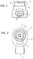
- the vehicle-lamp lighting-on device 1, as shown in Figs. 1 through 4, is generally made up of a body case 2, a socket 10 and a lighting-on transformer 30, and the like.
- the body case 2 and the socket 10 are both made of synthetic resin.
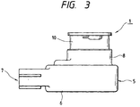
- the synthetic resin body case 2 includes a major portion 5 and an extended portion 6 extended outwardly of the circular portion 5.
- the front end of the major portion 5 is opened to provide a circular connection opening 3 defined by a ring-like circumferential wall 8.
- the extended portion 6 is shaped like U when viewed from above.
- a cylindrical protrusion which has a through-hole 7 longitudinally formed therein, is protruded outward from the central part of the bottom of the U-shape of the extended portion 6. Lead wires are lead out through the through-hole 7 of the cylindrical protrusion.
- a printed circuit board 90 is placed on the bottom surface of the body case 2. The printed circuit board 90 is connected to the inner ends of needle terminals 95. A space is formed in the extended portion 6 of the body case 2.
- the space is used for mounting a circuit component (not shown), e.g., a capacitor, on the printed circuit board 90.
- a circuit component e.g., a capacitor
- An opening 9 is formed in the rear side of the body case 2.
- the lighting-on transformer 30, the printed circuit board 90 and others are inserted into the body case 2, through the opening 9.
- the opening 9 is covered with a cover 9a.
- the socket 10 when attached, is inserted into the connection opening 3 of the major portion 5 of the body case 2.
- the socket 10 cylindrical in shape, includes a high-voltage terminal 12 located at the central part thereof and a couple of low-voltage terminals 13 (one of them is illustrated in Fig. 4), which are spaced outward from the high-voltage terminal 12.
- the lighting-on transformer 30 is constructed such that a coil bobbin 40 is placed in a core housing 31 having an iron core 35.
- the core housing 31 is made of magnetic material, e.g., ferrite.
- a couple of core blocks 32 and 33, the outside diameters of which are equal, are coupled together into a cylindrical body of a short length, or the core housing 31.
- the outside diameter of the cylindrical body is selected to be equal to the inside diameter of the major portion 5 of the body case 2.
- a specific example of the cylindrical block is 37mm in diameter.
- the core block 32 of the core housing 31 is a thin disc-like block of approximately 2mm thick, and serves as a front wall of the core housing 31.
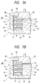
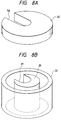
- a coil bobbin 40 is injection molded onto the core block 32 into a single unit. As shown in Fig. 8A, a thorough-hole 54 is formed through the core block 32 while being located slightly deviated from the center of the core block 32.
- the core block 33 of the core housing 31 includes a cylindrical wall 34, an iron core 35 and a rear wall 36 which interconnects the cylindrical wall 34 and the iron core 35.
- the cylindrical wall 34 is raised vertically from the outer circumferential edge of the rear wall 36.
- the iron core 35 is raised vertically from the central part of the core block 33.
- a through-hole 37 is extended passing through the iron core 35 in its lengthwise direction while being located slightly deviated from the center of the core block 33.
- a thick portion 48 of the coil bobbin 40 (which will be described later) is inserted into the through-hole 37.
- the core block 33 is manufactured as an individual component part, and, in assembling, is applied to the rear side of the unit structure including the core block 32 and the coil bobbin 40 as will be described later.
- Three holes 39 are formed in the rear wall 36.
- the iron core 35 may be provided in the core block 32, which is located on the front side of the core block 33.
- the coil bobbin 40 is made of synthetic resin. As shown, the coil bobbin 40 includes a cylindrical bobbin base 46 to be brought into close contact with the outer surface of the iron core 35. A plural number of flange-like plates 41 are extended radially and outwardly from the outer surface of the cylindrical bobbin base 46. The flange-like plates 41 and the inner surface of the cylindrical wall 34 of the core block 33 substantially define spaces 42, intermediate spaces 44 located between the spaces 42, and another space 45. A secondary coil 49 is successively wound in the spaces 42 and the intermediate space 44, and a primary coil 50 like a thin film is wound in the space 45.
- the coil bobbin is made of rubber, resin such as LCP, PPE, PBT, polyimide and polyamide, and ceramic such as alumina, mica, silica, glass and Si 3 N 4 .
- a protruded part 52a and other protruded parts 52b are protruded from the rear side of the coil bobbin 40.
- Those protruded parts 52a and 52b are inserted into the three holes 39 (two of them are illustrated in the figure) of the rear wall 36, whereby the coil bobbin 40 and the core block 33 are coupled together.
- Through-holes are formed in the protruded parts 52a and 52b. Both ends of the primary coil 50 are led out through the through-holes.
- the winding end terminal of the secondary coil 49 and both ends of the primary coil 50 are connected to related electrical paths on the printed circuit board 90.
- the coil bobbin 40 is inserted into the through-hole 37 of the iron core 35; it has the thick portion 48 that passes through the core block 32; and a connection hole 47 is formed in the thick portion 48 while being located deviated from the center of the coil bobbin 40.
- a shielding plate 56 that is continuous to the coil bobbin 40 is provided on the front side of the core block 32.
- the connection hole 47 is formed in the shielding plate 56.
- a cylindrical part 57 is raised from the shielding plate 56 while being coaxial with the connection hole 47.
- High-voltage side connecting piece 55 is inserted into the connection hole 47 (Fig. 5).
- the winding start terminal (high voltage terminal) of the secondary coil 49 is introduced into the connection hole 47 through a through-hole 53 of the thick portion 48 and electrically connected to the high-voltage side connecting piece 55.
- the secondary coil 49 is successively wound in the spaces 42 through the intermediate spaces 44, and the winding end terminal of the secondary coil is led out to the rear side of the lighting-on transformer 30, through the protruded part 52.
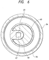
- An insulating ring 70 is placed on and along the inner side of the cylindrical wall 34 of the core housing 31.
- the diameter of each flange-like plate 41 is selected so that the tip of the flange-like plate 41 fails to come in contact with the inner side of the insulating ring 70. Therefore, gaps 72 are formed between the tips of the flange-like plates 41 and the inner side of the insulating ring 70.
- the insulating ring 70 has a positioning protrusion 71.
- the positioning protrusion 71 while being protruded inward, is formed at the end of the insulating ring 70 where the ring is abutted against a portion of the rear wall 36 which is located close to the winding end terminal (low-voltage terminal) of the secondary coil 49.
- the height of the positioning protrusion 71 corresponds to each gap 72. More specifically, the tip of the positioning protrusion 71 of the insulating ring 70 is made to press contact with the circumferential edge of the lowermost flange-like plate 41 of the coil bobbin 40, which is closest to the rear wall 36 of the core block 33.
- the coil bobbin 40 is positioned with respect to the core housing 31, and the gaps 72 are secured between the tips of the flange-like plates 41 (except the lowermost flange-like plate 41) and the inner side of the insulating ring 70. If required, the gaps 72 may be impregnated with insulating material of resin, for example. It is noted that the positioning protrusion 71 is located close to the low-voltage side. The reason for this is that the contact of the positioning protrusion 71 with the coil bobbin 40 creates no creepage discharge since high voltage is not present. A gap 73 for insulation is formed between the core block 32 serving as the front wall of the core housing 31 and the uppermost flange-like plate 41. Incidentally, in this case, it is not necessary that the positioning protrusion 71 is always provide. For example, as shown in Fig. 7B, there are no positioning protrusion 71.
- the coil bobbin 40 is electrically insulated from the cylindrical wall 34 of the core block 33. Provision of the insulating ring 70 prevents an aerial' discharge which otherwise would occur. Because of the present of the gaps 72, the coil bobbin 40 comes in contact with only two positions of the core housing 31; the inner wall of a fore part (high voltage side) of the core housing and the inner walls of a rear part (low voltage side). The gaps 72 separate the coil bobbin 40 from the inner wall of the insulating ring 70.
- a surface distance of the coil bobbin 40 is increased, viz., it ranges from a position where the lowermost flange-like plate 41 of the coil bobbin 40 is in contact with the core block 33 to another position where the uppermost flange-like plate 41 is in contact with the core block 32.
- the voltage drop in question takes place in particular in the high voltage region of the device.
- a route ranging from the secondary coil 49 in the uppermost space 42 to a contact surface of the coil bobbin 40 where it comes in contact with the core block 32, through the surface of the flange-like plates 41 is a key route for the flow of current of the creepage discharge.
- the insulating gap 73 is present between the uppermost flange-like plate 41 and the core block 32 in the high-voltage transformer of the present embodiment. The presence of the insulating gap 73 considerably elongates the surface distance for the creepage to be in excess of the maximum distance within which the creepage discharge will take place.
- the high-voltage transformer of the embodiment has the gaps 72 and 73, and hence is free from the creepage discharge by the high voltage produced from the secondary coil 49 of the transformer, and the voltage drop resulting from the creepage as well.
- the high-voltage transformer 30 thus constructed is covered with the core housing 31, it has a neat, single structure. With formation of the extended portion 6, an orderly space is formed in the body case 2.
- connection opening 3 a couple of cylindrical portions 61 are provided at locations close to the circumferential edge of the connection opening, in association with the low-voltage terminals 13 of the socket 10. Low-voltage side connecting pieces 62 are inserted into the cylindrical portions 61.
- the cylindrical portions 61 are integral with the body case 2.
- Low-voltage metal pieces (earthing paths) 63 are coupled into the body case 2 by insert molding.
- One end of each earthing path 63 is put in the corresponding cylindrical portion 61, and connected to the corresponding low-voltage side connecting piece 62.
- the other end 64 of the earthing path 63 is led to the rear side, passed through the corresponding through-hole of the printed circuit board 90, and connected to a low-voltage path (earthing path) on the printed circuit board 90.
- the cylindrical portion 61 may be integrally connected to the low-voltage side connecting piece 62.
- a metal sheet is bent to take a triangular shape (in cross section) with its apex being opened.
- the high-voltage terminal 12 is inserted into the opening of the high-voltage side connecting piece 55, and the two low-voltage terminals 13 are inserted into the openings of the low-voltage side connecting pieces 62, whereby electrical connection is set up.
- the high-voltage side connecting piece 55 may be integrally connected to the connection hole 47.
- the vehicle-lamp lighting-on device may be constructed in such a simple manner that the high-voltage transformer 30, the printed circuit board 90 and the like are inserted into the body case 2 through the opening 9, and the connection opening 3 is covered with the insulating shielding plate 56, and the socket 10 is inserted into and fixed to the connection opening 3.
- voltage of about 400V is applied to the lead wires that are connected to the needle terminals 95 extended into the through-hole 7.
- the voltage then is applied to the primary coil of the high-voltage transformer through a related circuity on the printed circuit board 90.
- the transformer boosts the voltage to voltage of 13kV or higher and the boosted voltage, while not causing a creepage discharge, is applied from the secondary winding 49 to the high-voltage side connecting piece 55 and in turn to the high-voltage terminal 12 of the socket 10.
- the thus constructed vehicle-lamp lighting-on device 1 is attached to the front of the engine room of a vehicle; a discharge lamp (not shown), e.g., a metal halide lamp, is attached to the socket 10; the low-voltage terminals 13 are connected to the peripheral electrodes of the discharge lamp; the high-voltage terminal 12 is connected to the center electrode; and high voltage of 13kV or higher is applied to the discharge lamp to light on the lamp.
- a discharge lamp e.g., a metal halide lamp
- the high-voltage transformer may be applied to the ignition device of the vehicle.
- an insulating ring 70 is placed on and along the inner surface of the core housing 31, and gaps 72 and 73 are formed between the tips of the flange-like plates 41 of the coil bobbin 40 and the inner side of the insulating ring 70.
- the gaps 72 and 73 and the insulating ring 70 are provided between the coil bobbin 40 and the inner wall of the core housing 31, so that the flange-like plates 41 of the coil bobbin 40 do not come in contact with the inner surface of cylindrical wall 34 of the core housing 31. Therefore, no areal discharge takes place. Further, a surface distance of the coil bobbin 40 ranges to a contact surface of the coil bobbin 40 where it comes in contact with the front wall of the core housing 31. The surface distance is elongated. The voltage drop by the creepage discharge does no occur.
- the positioning protrusion 71 is formed at a location on the insulating ring 70, which is close to the low voltage side of the secondary coil 49 on the insulating ring 70.
- the tip of the positioning protrusion 71 of the insulating ring 70 is made to press contact with the circumferential edge of a flange-like plate 41 of the coil bobbin 40, whereby the coil bobbin 40 is uniformly positioned within the core housing 31.
- the gaps 72 are made uniform around the coil bobbin 40 and a satisfactory surface distance is secured.
Landscapes
- Engineering & Computer Science (AREA)
- Power Engineering (AREA)
- Insulating Of Coils (AREA)
- Non-Portable Lighting Devices Or Systems Thereof (AREA)
Applications Claiming Priority (3)
| Application Number | Priority Date | Filing Date | Title |
|---|---|---|---|
| JP9176355A JPH118140A (ja) | 1997-06-16 | 1997-06-16 | 高圧トランス |
| JP176355/97 | 1997-06-16 | ||
| JP17635597 | 1997-06-16 |
Publications (3)
| Publication Number | Publication Date |
|---|---|
| EP0886286A2 true EP0886286A2 (de) | 1998-12-23 |
| EP0886286A3 EP0886286A3 (de) | 2000-03-22 |
| EP0886286B1 EP0886286B1 (de) | 2004-09-01 |
Family
ID=16012168
Family Applications (1)
| Application Number | Title | Priority Date | Filing Date |
|---|---|---|---|
| EP98110930A Expired - Lifetime EP0886286B1 (de) | 1997-06-16 | 1998-06-15 | Hochspannungstransformator und Beleuchtungsvorrichtung mit Fahrzeuglampe dafür |
Country Status (4)
| Country | Link |
|---|---|
| US (1) | US5959521A (de) |
| EP (1) | EP0886286B1 (de) |
| JP (1) | JPH118140A (de) |
| DE (1) | DE69825943T2 (de) |
Cited By (5)
| Publication number | Priority date | Publication date | Assignee | Title |
|---|---|---|---|---|
| EP1135009A3 (de) * | 2000-03-10 | 2003-12-03 | Stanley Electric Corporation | Zündvorrichtung einer Entladungslampe |
| WO2005022576A3 (de) * | 2003-08-26 | 2005-09-01 | Patent Treuhand Ges Fuer Elektrische Gluehlampen Mbh | Lampensockel für eine hochdruckentladungslampe und hochdruckentladungslampe |
| WO2006084440A1 (de) * | 2005-02-11 | 2006-08-17 | Patent-Treuhand-Gesellschaft für elektrische Glühlampen mbH | Lampensockel für eine hochdruckentladungslampe und hochdruckentladungslampe |
| WO2010060837A1 (de) * | 2008-11-28 | 2010-06-03 | Osram Gesellschaft mit beschränkter Haftung | Integrierte gasentladungslampe und zündtransformator für eine integrierte gasentladungslampe |
| WO2010091869A1 (de) * | 2009-02-16 | 2010-08-19 | Sumida Components & Moduls Gmbh | Gehäuse für einen zündtransformator, transformatorvorrichtung und vorschaltelektronik für eine gasentladungslampe |
Families Citing this family (18)
| Publication number | Priority date | Publication date | Assignee | Title |
|---|---|---|---|---|
| JP3752803B2 (ja) * | 1997-09-09 | 2006-03-08 | 東洋電装株式会社 | 放電灯点灯装置 |
| US6600402B1 (en) | 1998-10-20 | 2003-07-29 | Vlt Corporation | Bobbins, transformers, magnetic components, and methods |
| US6593836B1 (en) * | 1998-10-20 | 2003-07-15 | Vlt Corporation | Bobbins, transformers, magnetic components, and methods |
| US6602105B1 (en) | 1998-10-21 | 2003-08-05 | Michael Sussell | Illumination system for balloons with thin film valves |
| JP2001257085A (ja) * | 2000-03-10 | 2001-09-21 | Hitachi Ferrite Electronics Ltd | 放電灯起動装置 |
| WO2002016825A1 (fr) * | 2000-08-18 | 2002-02-28 | Mitsubishi Denki Kabushiki Kaisha | Douille et transformateur pour lampe et procede de fabrication d'un transformateur pour lampe |
| DE10339588A1 (de) * | 2003-08-26 | 2005-03-24 | Patent-Treuhand-Gesellschaft für elektrische Glühlampen mbH | Lampensockel für eine Hochdruckentladungslampe und Hochdruckentladungslampe |
| US7046112B2 (en) * | 2004-01-26 | 2006-05-16 | Halliburton Energy Services, Inc. | Logging tool induction coil form |
| DE102005019763B4 (de) * | 2005-04-28 | 2008-07-03 | Sma Technologie Ag | Wechselrichter mit elektrischem Wickelgut |
| CN101529536B (zh) * | 2006-10-31 | 2011-12-28 | 三菱电机株式会社 | 板型变压器及放电灯点亮装置 |
| DE102007025421B4 (de) * | 2007-05-31 | 2009-07-30 | Vogt Electronic Components Gmbh | Zündtransformator und Zündmodul |
| JP4881450B2 (ja) * | 2010-02-17 | 2012-02-22 | 株式会社東芝 | 電子機器および車両 |
| DE102010017902B4 (de) * | 2010-04-21 | 2012-08-30 | Borgwarner Beru Systems Gmbh | Zündspule |
| WO2015091202A1 (en) * | 2013-12-19 | 2015-06-25 | Koninklijke Philips N.V. | High voltage transformer comprising a coil bobbin for carrying a high voltage winding |
| US20160190722A1 (en) * | 2014-12-24 | 2016-06-30 | Yazaki Corporation | Connector |
| US9742081B1 (en) * | 2016-05-24 | 2017-08-22 | Te Connectivity Corporation | Press-fit circuit board connector |
| JP6415654B1 (ja) * | 2017-07-28 | 2018-10-31 | イリソ電子工業株式会社 | 電子部品 |
| DE102019113068A1 (de) * | 2019-05-17 | 2020-11-19 | Marelli Automotive Lighting Reutlingen (Germany) GmbH | Leiterplatte mit einer Steckverbindung |
Family Cites Families (12)
| Publication number | Priority date | Publication date | Assignee | Title |
|---|---|---|---|---|
| FR2344109A1 (fr) * | 1976-03-08 | 1977-10-07 | Ungari Serge | Transformateur statique a noyau central |
| JPS57176602A (en) * | 1981-04-24 | 1982-10-30 | Toshiba Electric Equip | Lighting apparatus |
| JPS59130002A (ja) * | 1983-01-14 | 1984-07-26 | 東芝ライテック株式会社 | 照明装置 |
| EP0212609B1 (de) * | 1985-08-22 | 1989-05-17 | Siemens Aktiengesellschaft | Elektrische Spule |
| US4725805A (en) * | 1985-12-25 | 1988-02-16 | Toko Kabushiki Kaisha | Electric current control type variable inductor |
| DE8711808U1 (de) * | 1987-09-01 | 1987-10-15 | Blaupunkt-Werke Gmbh, 31139 Hildesheim | Transformator |
| JPH01140705A (ja) * | 1987-11-27 | 1989-06-01 | Toshiba Corp | 電子レンジ用トランス |
| JPH05152138A (ja) * | 1991-11-28 | 1993-06-18 | Tohoku Ricoh Co Ltd | 高周波コア用ボビン |
| JPH07114805A (ja) * | 1993-10-15 | 1995-05-02 | Matsushita Electric Works Ltd | 車両用前照灯装置 |
| JP2963364B2 (ja) * | 1995-05-12 | 1999-10-18 | 松下電工株式会社 | 車両用前照灯装置 |
| JP2983883B2 (ja) * | 1995-05-12 | 1999-11-29 | 松下電工株式会社 | 車両用前照灯装置 |
| JP3791021B2 (ja) * | 1995-05-12 | 2006-06-28 | 松下電工株式会社 | 車両用前照灯装置 |
-
1997
- 1997-06-16 JP JP9176355A patent/JPH118140A/ja active Pending
-
1998
- 1998-06-15 DE DE69825943T patent/DE69825943T2/de not_active Expired - Fee Related
- 1998-06-15 EP EP98110930A patent/EP0886286B1/de not_active Expired - Lifetime
- 1998-06-16 US US09/097,658 patent/US5959521A/en not_active Expired - Fee Related
Cited By (9)
| Publication number | Priority date | Publication date | Assignee | Title |
|---|---|---|---|---|
| EP1135009A3 (de) * | 2000-03-10 | 2003-12-03 | Stanley Electric Corporation | Zündvorrichtung einer Entladungslampe |
| WO2005022576A3 (de) * | 2003-08-26 | 2005-09-01 | Patent Treuhand Ges Fuer Elektrische Gluehlampen Mbh | Lampensockel für eine hochdruckentladungslampe und hochdruckentladungslampe |
| WO2006084440A1 (de) * | 2005-02-11 | 2006-08-17 | Patent-Treuhand-Gesellschaft für elektrische Glühlampen mbH | Lampensockel für eine hochdruckentladungslampe und hochdruckentladungslampe |
| US7696699B2 (en) | 2005-02-11 | 2010-04-13 | Osram Gesellschaft Mit Beschraenkter Haftung | Lamp base for a high-pressure discharge lamp and corresponding high-pressure discharge lamp |
| WO2010060837A1 (de) * | 2008-11-28 | 2010-06-03 | Osram Gesellschaft mit beschränkter Haftung | Integrierte gasentladungslampe und zündtransformator für eine integrierte gasentladungslampe |
| CN102227786A (zh) * | 2008-11-28 | 2011-10-26 | 欧司朗有限公司 | 集成的气体放电灯和用于集成的气体放电灯的点火变压器 |
| US8436711B2 (en) | 2008-11-28 | 2013-05-07 | Osram Gesellschaft Mit Beschrankter Haftung | Integrated gas discharge lamp and ignition transformer for an integrated gas discharge lamp |
| CN102227786B (zh) * | 2008-11-28 | 2013-09-04 | 欧司朗股份有限公司 | 集成的气体放电灯和用于集成的气体放电灯的点火变压器 |
| WO2010091869A1 (de) * | 2009-02-16 | 2010-08-19 | Sumida Components & Moduls Gmbh | Gehäuse für einen zündtransformator, transformatorvorrichtung und vorschaltelektronik für eine gasentladungslampe |
Also Published As
| Publication number | Publication date |
|---|---|
| DE69825943D1 (de) | 2004-10-07 |
| JPH118140A (ja) | 1999-01-12 |
| DE69825943T2 (de) | 2005-01-20 |
| US5959521A (en) | 1999-09-28 |
| EP0886286A3 (de) | 2000-03-22 |
| EP0886286B1 (de) | 2004-09-01 |
Similar Documents
| Publication | Publication Date | Title |
|---|---|---|
| EP0886286B1 (de) | Hochspannungstransformator und Beleuchtungsvorrichtung mit Fahrzeuglampe dafür | |
| EP0863518B1 (de) | Beleuchtungsvorrichtung für Fahrzeugleuchte | |
| US7710231B2 (en) | Ignition coil | |
| EP0387993A1 (de) | Zündanordnung für Brennkraftmaschine mit einem Primärwicklungsmodul | |
| JPH08130127A (ja) | 高圧トランス及び放電灯回路 | |
| EP0852455B1 (de) | Steuerungsgerät für eine Fahrzeugbeleuchtung | |
| US7585177B2 (en) | Discharge lamp socket | |
| US7746211B2 (en) | Lamp transformer assembly | |
| US8193891B2 (en) | High voltage transformer with space-saving primary windings | |
| US7855625B2 (en) | Lamp transformer | |
| JP4915892B2 (ja) | 高圧放電ランプ用のランプ口金および高圧放電ランプ | |
| JPH1116749A (ja) | 高圧トランス | |
| US20010020825A1 (en) | Starting device for discharge lamp | |
| JPH11185504A (ja) | 車両用点灯起動装置 | |
| JP2004207405A (ja) | 電磁装置および高電圧発生装置 | |
| JPH117807A (ja) | 車両用点灯起動装置 | |
| JPH11242997A (ja) | 車両用点灯起動装置 | |
| JPH1154344A (ja) | 高圧トランス | |
| JPH10255507A (ja) | 車両用点灯起動装置 | |
| JP2552112Y2 (ja) | 昇圧装置 | |
| JP2002013458A (ja) | 内燃機関用点火装置 | |
| KR100715387B1 (ko) | 방전등 점등 장치 | |
| JP3962889B2 (ja) | Hidランプ点灯装置 | |
| JPH10250458A (ja) | 車両用点灯起動装置 | |
| JPH10302537A (ja) | 放電灯装置 |
Legal Events
| Date | Code | Title | Description |
|---|---|---|---|
| PUAI | Public reference made under article 153(3) epc to a published international application that has entered the european phase |
Free format text: ORIGINAL CODE: 0009012 |
|
| AK | Designated contracting states |
Kind code of ref document: A2 Designated state(s): DE FR GB IT |
|
| AX | Request for extension of the european patent |
Free format text: AL;LT;LV;MK;RO;SI |
|
| PUAL | Search report despatched |
Free format text: ORIGINAL CODE: 0009013 |
|
| AK | Designated contracting states |
Kind code of ref document: A3 Designated state(s): AT BE CH CY DE DK ES FI FR GB GR IE IT LI LU MC NL PT SE |
|
| AX | Request for extension of the european patent |
Free format text: AL;LT;LV;MK;RO;SI |
|
| 17P | Request for examination filed |
Effective date: 20000911 |
|
| AKX | Designation fees paid |
Free format text: DE FR GB IT |
|
| 17Q | First examination report despatched |
Effective date: 20030128 |
|
| GRAP | Despatch of communication of intention to grant a patent |
Free format text: ORIGINAL CODE: EPIDOSNIGR1 |
|
| GRAS | Grant fee paid |
Free format text: ORIGINAL CODE: EPIDOSNIGR3 |
|
| GRAA | (expected) grant |
Free format text: ORIGINAL CODE: 0009210 |
|
| AK | Designated contracting states |
Kind code of ref document: B1 Designated state(s): DE FR GB IT |
|
| PG25 | Lapsed in a contracting state [announced via postgrant information from national office to epo] |
Ref country code: IT Free format text: LAPSE BECAUSE OF FAILURE TO SUBMIT A TRANSLATION OF THE DESCRIPTION OR TO PAY THE FEE WITHIN THE PRESCRIBED TIME-LIMIT;WARNING: LAPSES OF ITALIAN PATENTS WITH EFFECTIVE DATE BEFORE 2007 MAY HAVE OCCURRED AT ANY TIME BEFORE 2007. THE CORRECT EFFECTIVE DATE MAY BE DIFFERENT FROM THE ONE RECORDED. Effective date: 20040901 Ref country code: FR Free format text: LAPSE BECAUSE OF FAILURE TO SUBMIT A TRANSLATION OF THE DESCRIPTION OR TO PAY THE FEE WITHIN THE PRESCRIBED TIME-LIMIT Effective date: 20040901 |
|
| REG | Reference to a national code |
Ref country code: GB Ref legal event code: FG4D |
|
| REF | Corresponds to: |
Ref document number: 69825943 Country of ref document: DE Date of ref document: 20041007 Kind code of ref document: P |
|
| PG25 | Lapsed in a contracting state [announced via postgrant information from national office to epo] |
Ref country code: GB Free format text: LAPSE BECAUSE OF NON-PAYMENT OF DUE FEES Effective date: 20050615 |
|
| PLBE | No opposition filed within time limit |
Free format text: ORIGINAL CODE: 0009261 |
|
| STAA | Information on the status of an ep patent application or granted ep patent |
Free format text: STATUS: NO OPPOSITION FILED WITHIN TIME LIMIT |
|
| 26N | No opposition filed |
Effective date: 20050602 |
|
| EN | Fr: translation not filed | ||
| PG25 | Lapsed in a contracting state [announced via postgrant information from national office to epo] |
Ref country code: DE Free format text: LAPSE BECAUSE OF NON-PAYMENT OF DUE FEES Effective date: 20060103 |
|
| GBPC | Gb: european patent ceased through non-payment of renewal fee |
Effective date: 20050615 |