EP0877112B1 - Procédé et dispositif pour broder des ouvrages tubulaires - Google Patents
Procédé et dispositif pour broder des ouvrages tubulaires Download PDFInfo
- Publication number
- EP0877112B1 EP0877112B1 EP98810039A EP98810039A EP0877112B1 EP 0877112 B1 EP0877112 B1 EP 0877112B1 EP 98810039 A EP98810039 A EP 98810039A EP 98810039 A EP98810039 A EP 98810039A EP 0877112 B1 EP0877112 B1 EP 0877112B1
- Authority
- EP
- European Patent Office
- Prior art keywords
- embroidering
- sewing machine
- embroidery
- embroidering device
- free arm
- Prior art date
- Legal status (The legal status is an assumption and is not a legal conclusion. Google has not performed a legal analysis and makes no representation as to the accuracy of the status listed.)
- Expired - Lifetime
Links
Images


Classifications
-
- D—TEXTILES; PAPER
- D05—SEWING; EMBROIDERING; TUFTING
- D05B—SEWING
- D05B21/00—Sewing machines with devices for automatically controlling movement of work-carrier relative to stitch-forming mechanism in order to obtain particular configuration of seam, e.g. programme-controlled for sewing collars, for attaching pockets
-
- D—TEXTILES; PAPER
- D05—SEWING; EMBROIDERING; TUFTING
- D05B—SEWING
- D05B73/00—Casings
- D05B73/04—Lower casings
Definitions
- the invention relates to a method for embroidery of tubular sewing material according to the preamble of Claim 1 and a device for embroidering tubular sewing material according to the preamble of Claim 3.
- the sewing machine can also be used as an embroidery machine with a controlled embroidery frame.
- the embroidery frame is mounted on the embroidery frame carrier of such an embroidery device so as to be displaceable in the X and Y directions.
- the embroidery device is designed as a structural unit, has an essentially L-shaped outline and lies snugly against the free arm both on the back of the sewing machine and on the front side and is detachably connected to it.
- the surface of the embroidery device and the surface of the free arm form a common, closed work surface.
- the object of the present invention is therefore to create a method and a device with which both embroidery of flat as well as of tubular structures is possible.
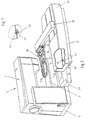
- the sewing machine 2 shown in FIG. 1 is not explained in detail, since its structure is well known from the prior art and is irrelevant to the subject matter of the invention. In addition, only the parts of the sewing machine 2 necessary for the explanation of the invention are designated and explained in more detail.
- the reference numeral 1 denotes the sewing machine housing, which is placed on a base plate 5 and has an essentially L-shaped shape.
- the free arm 3 is formed on the vertical leg 4 of the machine housing 1 at a distance from the base plate 5. In its free end, not visible, the gripper is drivably mounted below the tap hole 7.
- a needle 11 is inserted above the tap hole 7 on the needle bar 9.
- a screen 13 is shown schematically as a rectangle.
- a differently designed display or control unit could also be provided.
- a trackball 15 is also provided on the machine housing 1 on the same side.
- the assigned actuation keys are designated 16.
- Another row of keys 17 is used to select special functions. All the elements necessary for the thread guide and the thread are not designated or shown in detail because they are not necessary for the description of the invention and its understanding and their design has no influence on the invention.
- An embroidery device 21 connects to the front end 19 of the free arm 3. The latter also lies flush against the rear side 23 of the free arm 3 and is mechanically connected to the machine 2 by means not shown.
- An embroidery frame carrier 25 is mounted on the embroidery device 21 so as to be displaceable in the X direction.
- An embroidery frame 27 is fastened to the embroidery frame carrier 25 so as to be movable in the Y direction.
- a possible design of the drive elements for the embroidery frame 27 is described in German utility model 29614512 U1.
- the drive means for the X / Y movements of an embroidery frame are well known from the prior art and therefore do not have to be explained in detail.
- the embroidery frame 27 can be moved in a known manner on a programmable path by means of a correspondingly designed control, not described or shown in detail. Accordingly, freely programmable patterns can be produced with the sewing machine 2 on a textile structure which is clamped in the embroidery frame 27.
- the mutual position between the embroidery device 21 and the free arm 3 of the sewing machine, as shown in Figures 1 and 2 corresponds to the prior art.
- the embroidery device 21 in both X and Y direction to form a space in one Distance a and b to the end face 19 and rear 23 of the Free arm 3.
- a spacer 29 inserted between the base plate 5 of the sewing machine 2 and the embroidery device 21. This is fixed to the base plate 5 of the Sewing machine 2 and a suitably designed base 31 the embroidery device 21 connected.
- the height h of the Spacer 29 corresponds approximately to the height of the Base plate 5 so that free access to insert tubular sewing material over the free-flying end 19 of the Freiarms 3 is guaranteed.
- the spacer 29 comprises mechanical holding and centering means which enable a positionally accurate connection of the embroidery device 21 to the base plate 5 or to the sewing machine 2.
- a rib-like, horizontal cam 33 and a cylindrical cam 35 with a vertical axis, which are formed on the spacer 29, serve as fastening and centering means.
- the two cams 33 and 35 engage in correspondingly designed recesses 37 and 39 on the base plate 5 (FIG. 5).
- the connection between the embroidery device 21 and the spacer 29 is carried out analogously.
- a direct connection between the embroidery device 21 and the sewing machine 2 can also be established with the same means if flat textiles are to be embroidered.
- a cam 41 which projects vertically above the surface of the spacer 29 and engages into the housing of the embroidery device 21 from below through a recess 43, interacts with a feeler 45 in order to sense the presence of the spacer 29. If the embroidery device 21 is attached to the sewing machine 2 by means of a spacer 29, the feeler 45 triggers a signal to the control device so that it only releases embroidery pattern control data for a restricted embroidery area.
- the sensing means 45 preferably consists of a light barrier which is actuated by the cam 41 acting as an aperture.
- the electrical power and control connections between the embroidery device 21 and the sewing machine 2 can be established in a conventional manner via an externally routed cable (not shown) or through plug connections (also not shown). The plug connections can be designed such that they are connected to the base plate 5 of the sewing machine 2 and to the embroidery device 21 at the same time as the spacer 29 is plugged together.
- the embroidery device 21 When the embroidery device 21 is connected to the sewing machine 2 with the aid of the spacer 29, the embroidery device 21 is no longer in contact with the free arm 3, but is shifted relative to it by the distances a or b (FIG. 4). This results in a limited use of the embroidery area compared to the use of the embroidery device 21 according to FIGS. 1 and 2. Accordingly, the use of a special embroidery frame 27a is necessary, which is equipped with means for bridging the space formed between the free arm 3 and the embroidery device 21. These means consist of a bridge part 30, which is preferably formed in one piece with the embroidery frame 27a.
- the embroidery hoop 27a is connected to the embroidery hoop carrier 25 in a known manner, whereby means for identifying the embroidery hoop can be provided in accordance with German utility model DE 29612102 U1.
- a signal is triggered, which has the effect that the X / Y control device for the embroidery frame 27a only permits movements in a restricted area which corresponds to the size relationships of the special embroidery frame 27a.
Landscapes
- Engineering & Computer Science (AREA)
- Textile Engineering (AREA)
- Sewing Machines And Sewing (AREA)
Claims (10)
- Procédé pour broder des ouvrages tubulaires sur un appareil à broder (21) pouvant être rapporté sur une machine à coudre (2) à bras en avancée, dans lequel l'appareil à broder (21) est fixé à la machine à coudre (2) et le cadre à broder (27) est mobile au-dessus du bras (3) en avancée, caractérisé par le fait qu'un espace intercalaire est formé entre l'appareil à broder (21) et le bras (3) en avancée, en vue du passage de l'ouvrage.
- Procédé selon la revendication 1, caractérisé par le fait que l'espace intercalaire est engendré par un organe d'espacement (29).
- Dispositif pour broder des ouvrages tubulaires en utilisant un appareil à broder (21) sur une machine à coudre (2) à bras en avancée, comprenant l'appareil à broder (21) muni d'un cadre à broder pouvant être animé de coulissements horizontaux au-dessus du bras (3) en avancée, dans la direction des X par l'intermédiaire d'un premier entraínement, et dans la direction des Y par l'intermédiaire d'un second entraínement ; un premier moyen pour la liaison mécanique de l'appareil à broder (21) ; et un second moyen pour la connexion électrique avec la machine à coudre (2), caractérisé par le fait qu'un espace intercalaire (a, b), autorisant l'insertion de l'ouvrage tubulaire, est réservé entre l'appareil à broder (21), et le bras (3) en avancée de la machine à coudre (2).
- Dispositif selon la revendication 3, caractérisé par le fait qu'un organe d'espacement (29) est interposé entre l'appareil à broder (21) et la machine à coudre (2).
- Dispositif selon la revendication 4, caractérisé par le fait que des moyens (33-39) sont ménagés, sur l'organe d'espacement (29), pour la liaison mécanique entre l'appareil à broder (21) et la machine à coudre (2).
- Dispositif selon l'une des revendications 4 ou 5, caractérisé par le fait que l'organe d'espacement (29) est relié à l'appareil à broder (21) et à la plaque d'embase (5) de la machine à coudre (2).
- Dispositif selon l'une des revendications 3 à 6, caractérisé par le fait que le cadre à broder (27a) comporte des moyens pour combler l'espace intercalaire entre le bras (3) en avancée et l'appareil à broder (21).
- Dispositif selon la revendication 7, caractérisé par le fait que les moyens consistent en une pièce d'entretoisement (30) faisant partie du cadre à broder (27a), ou interposée entre l'appareil à broder (21) et ledit cadre à broder (27a).
- Dispositif selon l'une des revendications 3 à 8, caractérisé par le fait que des moyens d'exploration (45) sont prévus sur l'appareil à broder (21), pour explorer la présence de l'organe d'espacement (29).
- Dispositif selon la revendication 9, caractérisé par le fait que les moyens d'exploration (45) englobent une barrière photo-électrique et un mentonnet (41) agissant comme un diaphragme.
Applications Claiming Priority (3)
| Application Number | Priority Date | Filing Date | Title |
|---|---|---|---|
| CH991/97 | 1997-04-28 | ||
| CH99197 | 1997-04-28 | ||
| CH99197 | 1997-04-28 |
Publications (3)
| Publication Number | Publication Date |
|---|---|
| EP0877112A2 EP0877112A2 (fr) | 1998-11-11 |
| EP0877112A3 EP0877112A3 (fr) | 1999-04-21 |
| EP0877112B1 true EP0877112B1 (fr) | 2001-09-12 |
Family
ID=4199922
Family Applications (1)
| Application Number | Title | Priority Date | Filing Date |
|---|---|---|---|
| EP98810039A Expired - Lifetime EP0877112B1 (fr) | 1997-04-28 | 1998-01-26 | Procédé et dispositif pour broder des ouvrages tubulaires |
Country Status (5)
| Country | Link |
|---|---|
| US (1) | US6019052A (fr) |
| EP (1) | EP0877112B1 (fr) |
| JP (1) | JPH10305185A (fr) |
| DE (1) | DE59801421D1 (fr) |
| TW (1) | TW363097B (fr) |
Cited By (1)
| Publication number | Priority date | Publication date | Assignee | Title |
|---|---|---|---|---|
| EP4497862A1 (fr) | 2023-07-22 | 2025-01-29 | BERNINA International AG | Ensemble cadre de broderie |
Families Citing this family (11)
| Publication number | Priority date | Publication date | Assignee | Title |
|---|---|---|---|---|
| JP4330728B2 (ja) * | 1999-10-05 | 2009-09-16 | 蛇の目ミシン工業株式会社 | 刺しゅう枠収納機構を備えたミシン |
| TW504529B (en) * | 2000-02-07 | 2002-10-01 | Gegauf Fritz Ag | Device for the embroidery of surface-shaped sewing material on a column-type, or free arm-type, sewing machine |
| JP4184020B2 (ja) * | 2002-09-30 | 2008-11-19 | 蛇の目ミシン工業株式会社 | 刺しゅう縫いミシン |
| US6994642B2 (en) | 2004-02-11 | 2006-02-07 | Adventure Trading Incorporated | Spherical crocheted object having embroidery and the method of manufacture thereof |
| JP4626359B2 (ja) * | 2005-03-29 | 2011-02-09 | ブラザー工業株式会社 | ミシン |
| JP4605457B2 (ja) * | 2005-03-30 | 2011-01-05 | ブラザー工業株式会社 | 刺繍機 |
| JP4551805B2 (ja) * | 2005-04-14 | 2010-09-29 | Juki株式会社 | 差動送りミシン |
| DE502006000763D1 (de) | 2005-11-07 | 2008-06-26 | Bernina Int Ag | Stickmodul für eine Freiarm-Nähmaschine |
| USD837839S1 (en) * | 2015-12-15 | 2019-01-08 | Bernina International Ag | Stitching module |
| CH718422A2 (de) * | 2021-03-11 | 2022-09-15 | Bernina Int Ag | Sticksystem und Stickrahmenanordnung. |
| US20250116043A1 (en) * | 2023-10-06 | 2025-04-10 | Gracewood Management, Inc. | Feed dog cover |
Family Cites Families (12)
| Publication number | Priority date | Publication date | Assignee | Title |
|---|---|---|---|---|
| JPS5940039B2 (ja) * | 1978-02-02 | 1984-09-27 | 蛇の目ミシン工業株式会社 | 自動刺繍ミシン |
| JP2649540B2 (ja) * | 1988-04-28 | 1997-09-03 | 蛇の目ミシン工業株式会社 | 刺しゅうミシン |
| JP2736422B2 (ja) * | 1988-10-11 | 1998-04-02 | 株式会社バルダン | 刺繍ミシンの保持枠 |
| JPH02259154A (ja) * | 1989-03-31 | 1990-10-19 | Janome Sewing Mach Co Ltd | ミシンにおける普通縫及び刺しゅう縫の切換装置 |
| JPH03207392A (ja) * | 1990-01-10 | 1991-09-10 | Sanshiro Omine | ミシン |
| JP2530946Y2 (ja) * | 1990-05-22 | 1997-04-02 | アイシン精機株式会社 | 刺繍枠駆動装置 |
| JP2879986B2 (ja) * | 1991-02-18 | 1999-04-05 | 蛇の目ミシン工業株式会社 | ミシンにおける刺しゅう枠カートリッジ装置 |
| JP2879272B2 (ja) * | 1991-05-31 | 1999-04-05 | 蛇の目ミシン工業株式会社 | 複合ミシンの分離型x−y駆動装置 |
| JP3292249B2 (ja) * | 1991-08-12 | 2002-06-17 | ブラザー工業株式会社 | ミシン及び刺繍縫い用アタッチメント並びに刺繍縫い用アタッチメント付きミシン |
| SE507683C2 (sv) * | 1994-08-12 | 1998-07-06 | Electrolux Ab | Broderienhet för symaskin |
| DE29614512U1 (de) * | 1996-08-21 | 1996-10-02 | Fritz Gegauf AG Bernina-Nähmaschinenfabrik, Steckborn, Thurgau | Vorrichtung zum lösbaren Befestigen eines Stickrahmens |
| US5832853A (en) * | 1997-02-27 | 1998-11-10 | Melco Industries, Inc. | Cap embroidery apparatus and method |
-
1998
- 1998-01-26 DE DE59801421T patent/DE59801421D1/de not_active Expired - Lifetime
- 1998-01-26 EP EP98810039A patent/EP0877112B1/fr not_active Expired - Lifetime
- 1998-03-09 TW TW087103416A patent/TW363097B/zh not_active IP Right Cessation
- 1998-03-16 US US09/039,757 patent/US6019052A/en not_active Expired - Lifetime
- 1998-04-27 JP JP10117296A patent/JPH10305185A/ja active Pending
Cited By (2)
| Publication number | Priority date | Publication date | Assignee | Title |
|---|---|---|---|---|
| EP4497862A1 (fr) | 2023-07-22 | 2025-01-29 | BERNINA International AG | Ensemble cadre de broderie |
| US12467176B1 (en) | 2023-07-22 | 2025-11-11 | Bernina International Ag | Embroidery frame arrangement |
Also Published As
| Publication number | Publication date |
|---|---|
| DE59801421D1 (de) | 2001-10-18 |
| EP0877112A2 (fr) | 1998-11-11 |
| TW363097B (en) | 1999-07-01 |
| EP0877112A3 (fr) | 1999-04-21 |
| US6019052A (en) | 2000-02-01 |
| JPH10305185A (ja) | 1998-11-17 |
Similar Documents
| Publication | Publication Date | Title |
|---|---|---|
| EP0877112B1 (fr) | Procédé et dispositif pour broder des ouvrages tubulaires | |
| DE3314126C2 (de) | Werkzeughalter | |
| DE3111812C2 (de) | Nähmaschine | |
| DE19983601B4 (de) | Steuereinrichtung für eine automatische Nähmaschine | |
| DE10015346B4 (de) | Näh- oder Stickmaschine, insbesondere Stickmaschine mit verbesserter Rahmenantriebsvorrichtung | |
| DE112006003923B4 (de) | Materialprüfmaschine | |
| EP0860533A2 (fr) | Procédé pour broder des motifs surdimensionnés | |
| DE102008045460A1 (de) | Nähmaschine | |
| DE8114009U1 (de) | "zusatzvorrichtung fuer eine knopfannaehmaschine" | |
| DE2728967C3 (de) | Nähmaschine zum Nähen kantenparalleler Randnähte in aus mehreren Stofflagen bestehenden Werkstücken | |
| EP1308548B1 (fr) | Machine à coudre et à broder | |
| DE3823945A1 (de) | Mehrzweck-naehmaschine | |
| DE1108052B (de) | Stoffvorschub-Zusatzapparat fuer Naehmaschinen | |
| EP1122350B1 (fr) | Dispositif pour broder une pièce textile plane sur une machine à coudre du type à bras libre ou à colonne | |
| DE3235576A1 (de) | Verfahren zur identifizierung eines naehgut-halters und naehautomat zur durchfuehrung des verfahrens | |
| CH673123A5 (fr) | ||
| DE3730406C2 (fr) | ||
| DE3920408A1 (de) | Fadenzufuhreinrichtung mit wenigstens einem fadenfuehrer fuer eine rundstrickmaschine | |
| DE19751011C2 (de) | Nähmaschine | |
| DE2831471C2 (de) | Kettelmaschine | |
| DE2617718C2 (de) | Handstrickmaschine | |
| DE10117042A1 (de) | Zusatzvorrichtung für Nähmaschinen | |
| DE2900804A1 (de) | Einrichtung zum besticken von warenbahnflaechen durch einen oder mehrere flaechen-stickkoepfe mit rapport | |
| DE3343238C2 (fr) | ||
| DE3409120A1 (de) | (arbeits)halteklammer fuer eine vierlochknopfnaehmaschine |
Legal Events
| Date | Code | Title | Description |
|---|---|---|---|
| PUAI | Public reference made under article 153(3) epc to a published international application that has entered the european phase |
Free format text: ORIGINAL CODE: 0009012 |
|
| AK | Designated contracting states |
Kind code of ref document: A2 Designated state(s): CH DE GB LI NL SE |
|
| AX | Request for extension of the european patent |
Free format text: AL;LT;LV;MK;RO;SI |
|
| PUAL | Search report despatched |
Free format text: ORIGINAL CODE: 0009013 |
|
| AK | Designated contracting states |
Kind code of ref document: A3 Designated state(s): AT BE CH DE DK ES FI FR GB GR IE IT LI LU MC NL PT SE |
|
| AX | Request for extension of the european patent |
Free format text: AL;LT;LV;MK;RO;SI |
|
| 17P | Request for examination filed |
Effective date: 19990420 |
|
| AKX | Designation fees paid |
Free format text: CH DE GB LI NL SE |
|
| GRAG | Despatch of communication of intention to grant |
Free format text: ORIGINAL CODE: EPIDOS AGRA |
|
| GRAG | Despatch of communication of intention to grant |
Free format text: ORIGINAL CODE: EPIDOS AGRA |
|
| GRAH | Despatch of communication of intention to grant a patent |
Free format text: ORIGINAL CODE: EPIDOS IGRA |
|
| 17Q | First examination report despatched |
Effective date: 20010412 |
|
| GRAH | Despatch of communication of intention to grant a patent |
Free format text: ORIGINAL CODE: EPIDOS IGRA |
|
| GRAA | (expected) grant |
Free format text: ORIGINAL CODE: 0009210 |
|
| AK | Designated contracting states |
Kind code of ref document: B1 Designated state(s): CH DE GB LI NL SE |
|
| REG | Reference to a national code |
Ref country code: CH Ref legal event code: NV Representative=s name: HANS RUDOLF GACHNANG PATENTANWALT Ref country code: CH Ref legal event code: EP |
|
| REF | Corresponds to: |
Ref document number: 59801421 Country of ref document: DE Date of ref document: 20011018 |
|
| REG | Reference to a national code |
Ref country code: GB Ref legal event code: IF02 |
|
| GBT | Gb: translation of ep patent filed (gb section 77(6)(a)/1977) |
Effective date: 20011212 |
|
| PLBE | No opposition filed within time limit |
Free format text: ORIGINAL CODE: 0009261 |
|
| STAA | Information on the status of an ep patent application or granted ep patent |
Free format text: STATUS: NO OPPOSITION FILED WITHIN TIME LIMIT |
|
| 26N | No opposition filed | ||
| REG | Reference to a national code |
Ref country code: CH Ref legal event code: PFA Owner name: BERNINA INTERNATIONAL AG Free format text: FRITZ GEGAUF AG BERNINA-NAEHMASCHINENFABRIK#SEESTRASSE#CH-8266 STECKBORN (CH) -TRANSFER TO- BERNINA INTERNATIONAL AG#SEESTRASSE 161#8266 STECKBORN (CH) |
|
| PGFP | Annual fee paid to national office [announced via postgrant information from national office to epo] |
Ref country code: GB Payment date: 20100118 Year of fee payment: 13 |
|
| PGFP | Annual fee paid to national office [announced via postgrant information from national office to epo] |
Ref country code: NL Payment date: 20100131 Year of fee payment: 13 |
|
| PGFP | Annual fee paid to national office [announced via postgrant information from national office to epo] |
Ref country code: SE Payment date: 20100126 Year of fee payment: 13 |
|
| REG | Reference to a national code |
Ref country code: NL Ref legal event code: V1 Effective date: 20110801 |
|
| REG | Reference to a national code |
Ref country code: SE Ref legal event code: EUG |
|
| GBPC | Gb: european patent ceased through non-payment of renewal fee |
Effective date: 20110126 |
|
| PG25 | Lapsed in a contracting state [announced via postgrant information from national office to epo] |
Ref country code: GB Free format text: LAPSE BECAUSE OF NON-PAYMENT OF DUE FEES Effective date: 20110126 |
|
| PG25 | Lapsed in a contracting state [announced via postgrant information from national office to epo] |
Ref country code: NL Free format text: LAPSE BECAUSE OF NON-PAYMENT OF DUE FEES Effective date: 20110801 |
|
| PG25 | Lapsed in a contracting state [announced via postgrant information from national office to epo] |
Ref country code: SE Free format text: LAPSE BECAUSE OF NON-PAYMENT OF DUE FEES Effective date: 20110127 |
|
| REG | Reference to a national code |
Ref country code: CH Ref legal event code: NV Representative=s name: GACHNANG AG PATENTANWAELTE, CH |
|
| PGFP | Annual fee paid to national office [announced via postgrant information from national office to epo] |
Ref country code: CH Payment date: 20140203 Year of fee payment: 17 Ref country code: DE Payment date: 20140130 Year of fee payment: 17 |
|
| REG | Reference to a national code |
Ref country code: DE Ref legal event code: R119 Ref document number: 59801421 Country of ref document: DE |
|
| REG | Reference to a national code |
Ref country code: CH Ref legal event code: PL |
|
| PG25 | Lapsed in a contracting state [announced via postgrant information from national office to epo] |
Ref country code: CH Free format text: LAPSE BECAUSE OF NON-PAYMENT OF DUE FEES Effective date: 20150131 Ref country code: LI Free format text: LAPSE BECAUSE OF NON-PAYMENT OF DUE FEES Effective date: 20150131 Ref country code: DE Free format text: LAPSE BECAUSE OF NON-PAYMENT OF DUE FEES Effective date: 20150801 |