EP0866159B1 - Zungennadel für maschenbildende Textilmaschinen - Google Patents
Zungennadel für maschenbildende Textilmaschinen Download PDFInfo
- Publication number
- EP0866159B1 EP0866159B1 EP98102391A EP98102391A EP0866159B1 EP 0866159 B1 EP0866159 B1 EP 0866159B1 EP 98102391 A EP98102391 A EP 98102391A EP 98102391 A EP98102391 A EP 98102391A EP 0866159 B1 EP0866159 B1 EP 0866159B1
- Authority
- EP
- European Patent Office
- Prior art keywords
- needle
- latch
- blade
- tongue
- upper side
- Prior art date
- Legal status (The legal status is an assumption and is not a legal conclusion. Google has not performed a legal analysis and makes no representation as to the accuracy of the status listed.)
- Expired - Lifetime
Links
- 239000004753 textile Substances 0.000 title claims description 3
- 210000002105 tongue Anatomy 0.000 description 102
- 238000009940 knitting Methods 0.000 description 8
- 230000007423 decrease Effects 0.000 description 3
- 238000000034 method Methods 0.000 description 3
- 230000000694 effects Effects 0.000 description 2
- 239000004744 fabric Substances 0.000 description 2
- 230000009191 jumping Effects 0.000 description 2
- 230000036316 preload Effects 0.000 description 2
- FGRBYDKOBBBPOI-UHFFFAOYSA-N 10,10-dioxo-2-[4-(N-phenylanilino)phenyl]thioxanthen-9-one Chemical compound O=C1c2ccccc2S(=O)(=O)c2ccc(cc12)-c1ccc(cc1)N(c1ccccc1)c1ccccc1 FGRBYDKOBBBPOI-UHFFFAOYSA-N 0.000 description 1
- 238000013459 approach Methods 0.000 description 1
- 230000009286 beneficial effect Effects 0.000 description 1
- 238000009944 hand knitting Methods 0.000 description 1
- 239000002184 metal Substances 0.000 description 1
Images

Classifications
-
- D—TEXTILES; PAPER
- D04—BRAIDING; LACE-MAKING; KNITTING; TRIMMINGS; NON-WOVEN FABRICS
- D04B—KNITTING
- D04B35/00—Details of, or auxiliary devices incorporated in, knitting machines, not otherwise provided for
- D04B35/02—Knitting tools or instruments not provided for in group D04B15/00 or D04B27/00
- D04B35/04—Latch needles
Definitions
- the invention relates to a latch needle for stitch-forming Textile machines, with a hook at one end bearing needle shaft that has a top and a Has back and in which, starting from the top, one extending in the longitudinal direction of the shaft Tongue slot is arranged.
- a needle tongue pivoted about an axis, which has a tongue shaft to which to usually ends with a tongue spoon.
- the needle tongue is between a closed position in which it is with a front part, i.e. the spoon, on the hook rests and a reserve can be swiveled in which it can be used the top of her tongue rests on the top of the shaft or in the vicinity.
- the tongue needle is driven in and out the needle tongue is controlled by the new one formed stitch, between these two layers back and forth moved here, as is known per se.
- a latch needle is known, the latch of which can be held in a partially open intermediate position by an associated spring element arranged in the latch slot.
- This partially open intermediate position of the needle tongue allows the thread to be inserted into the needle hook unimpeded when the knitted fabric is cast on for the first time, i.e. at the start of the knitting process or when picking up stitches, without it being necessary to use a brush-shaped needle opener which is otherwise common in knitting machines or to open all needle tongues by hand before striking the knitted fabric, which is associated with a considerable amount of work.
- Other embodiments of such tongue needles equipped with a spring element are known from DE 1 113 537 C1 , US Pat . No.
- the spring element can only be clamped in the shaft at one of its two ends (see, for example, DE 37 02 019 C1 ) or rest on its two ends on corresponding shoulders in the tongue slot (see, for example, US Pat. No. 3,050,968) .
- the arrangement is such that the needle tongue at the end of its tongue shaft lying in the tongue slot is designed as a cam element, on which a force is exerted by the spring element at least during part of its movement path from the closed position to the reserve.
- the end part of the latch shaft lying in the latch slot is provided with a first flattening, which corresponds to the tongue shaft top is arranged.
- the needle tongue is thereby held elastically in a stable intermediate layer adjacent to the reserve, in which the upper side of the tongue shaft is at a distance from the upper side of the needle shaft.
- a second flattening in the area of the underside of the tongue shaft also in cooperation with the spring element, defines the partially open position of the needle tongue, in which the spoon is at a distance from the needle hook, so that the thread can be inserted into the needle hook.
- the cam element has a "curved" (DE 1 113 537 C1) or a circularly curved curved surface which is concentric with the pivot axis of the needle tongue (US Pat. No. 3,050,968).
- this document also describes embodiments in which the first flattening, which determines a stable back of the needle tongue, is dispensed with.
- Knitting machines developed in which the drive the needles are made via linear motors.
- Knitting machines are external tongue control devices for example in the form of brushes or mechanical tongue openers (Metal aprons, etc.) for design reasons only with a relatively high technical effort possible or basically no longer usable.
- the object of the invention is therefore one with Spring element for tongue needle equipped tongue needle to create an uncontrolled jumping the needle tongue excluded from the reserve or is at least essentially prevented.
- the latch needle according to the invention the features of claim 1.
- this latch needle With this latch needle, this points to the end part of the Tongue shaft trained cam element, then to a flattening that determines the reserve and / or a transverse buckling edge a curved cam surface whose radial distance from the axis from the top of the tongue shaft steadily towards the bottom of the tongue shaft decreases.
- This cam surface can have an essentially circular arc shape be curved, with its center of curvature is offset from the pivot axis of the needle tongue, so that it forms an eccentric surface. The center of curvature is towards the top of the tongue shaft added.
- the cam surface can also be essentially be spiral or one have another steady course.
- the needle tongue In its reserve, the needle tongue is through the first Flattened and / or the crease edge positioned. If the Stitch loops during the expulsion movement of the needle in the needle tongue standing free is the reserve under the influence of the elastic attacking on it Forces in themselves strive, if necessary, to overcome the crease edge to an undefined middle position leap. In this movement, however, the tongue gets through hindered the spring element, the first with relative great preload on that of the swivel axis radially most distant part of the cam surface abuts and thus a strong braking on the needle tongue Frictional force. The needle tongue therefore remains in the immediate vicinity of the reserve.
- Needle tongue during the next following feed movement Needle from the one on the top of the needle shaft to the hook sliding loop is closed increasingly acting on the cam surface Braking force because of the radial distance of the cam surface the pivot axis of the tongue decreases continuously, with the result that the deflection and thus the preload of the Spring element become smaller.
- the needle tongue thus approaches the closed position ever smoother, which includes with regard to the Wear is an advantage and the quality of the goods is considerable improved.
- the cam surface can in itself continuously in the Reserve flattening, but is It is beneficial if they are training crosswise running crease edge or line at this first flattening or a surface on the top of the tongue shaft adjoined.
- the crease gives a more precise definition the position that the needle tongue is in its reserve occupies.
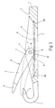
- the latch needle shown in Figures 1 and 3 has a needle shaft only partially illustrated 1 with a molded needle hook at one end 2 carries, the hook tip illustrated at 3 is.
- the top and back of the needle shaft 1 are denoted by 4 and 5 respectively.
- the needle shaft 1 is a to the longitudinal center plane the needle shaft symmetrical tongue slot 6 arranged, which has a breakthrough to the back 5 at 7.
- the tongue slot 6 is a needle tongue 8 pivoted, the tongue shaft 9 one in the area an end part 10 lying in the tongue slot 6 is provided with a cylindrical tongue bore 11, by means of which the needle tongue 8 on the pivot axis 12 containing cylindrical bearing element 13 mounted is.
- the bearing element 13 is in a corresponding Bores of the tongue slot 6 laterally delimiting Cheek bolts used or by two of these Cheeks pressed out cylindrical bearing journals educated.
- the end of the needle tongue 8 is at 14 indicated spoon designed with which the needle tongue 8th rests on the needle hook tip 3 in the closed position.
- the tongue slot 6 is a rod-shaped or leaflet-shaped, straight spring element 15 arranged on its two ends rests on two shoulders 160 which into the two opposite end walls the tongue slot 6 are incorporated.
- the spring element 15 can bend freely towards the back of the shaft 5, as shown in Fig. 3 by dashed lines is indicated.
- the end part 10 of the tongue shaft 9 is a cam element formed, which is supported on the spring element 15 is. It has one on the tongue shaft top 16 arranged first flat 17, which over the pivot axis 12 extends away and to which one curved cam surface 18 (Fig. 2) connects that without a shoulder merges into a second flattening 19 with a to the first flat 17 in this embodiment parallel surface 20 on the underside of the tongue shaft 21 along a transverse fold edge 22 cuts.
- the axis 12 of the tongue bore 11 is compared to the median plane indicated at 23 between the first flattening 17 and the parallel surface 20 the tongue shaft top 16 staggered out like this Fig. 2 can be seen.
- one could Offset to the tongue shaft underside 21 may be provided or there could be no offset.
- the curved one Cam surface 18 is designed such that its radial Distance from the axis 12, as indicated at 24 in Fig. 2 is, starting from a transverse fold edge 25, on which the cam surface 18 the first flattening 17 cuts to the tongue shaft underside 20 steadily decreases. This course of the cam surface 18 is thereby made obvious that dashed at 26 in Fig. 2 an imaginary arc around the axis 12 is entered.
- the Cam surface 18 curved in a circular arc. She is the one Detail of a cylinder, the one indicated at 27 Axis with respect to the axis 12 of the tongue bore 11 around a small amount towards the tongue shaft top 16 is offset. The cam surface 18 forms therefore in comparison to the wall of the tongue bore 11 an eccentric surface.
- the cam surface 18 a has another steady course, for example is curved in the shape of a spiral.
- the needle tongue 8 is in knitting between the 3 closed position shown in dashed lines in the her spoon 14 rests on the hook tip 3 and the in Fig. 1 illustrated with solid lines reserve pivotable.
- the needle tongue 8 lies in this reserve either, as shown in Fig. 1, on the top of the needle shaft 4 on, or, their top 16 is in a small distance from the top of the needle shaft 4.
- This reserve makes the needle tongue 8 stable kept their first flat 17 on the spring element 15 lies over a large area and / or that the crease edge 25, based on Fig. 2, to the left of the pivot axis 12 lies and determines the reserve. If with the feed movement the latch needle on the top of the needle shaft 4 mesh loops sliding along the top of the tongue shaft 16 accumulates, the needle tongue 8, based on Fig.
- the latch needle With the closing movement controlled by the stitch handle the needle tongue 8 in the course of the feed movement the latch needle takes the radial distance from the Spring element 15 engaging areas of the Cam surface 18 increasingly from the axis 12. That has as a result that the braking torque exerted on the needle tongue 8 is getting smaller, so the smoothness the needle tongue increases until its second flattening 19 comes to rest over the entire area on the spring element 15.
- the second flattening 19 defines that in FIG. 3 shown in solid lines and dashed lines in Fig. 1 partially open intermediate position of the needle tongue.
- the flattening 19 prevents, among other things, the needle tongue when closing on the hook tip 3 hits.
- Embodiments are also conceivable in which on the transverse folding edge 25 is dispensed with and the curved cam surface 18 steadily into the first Flat 17 or another surface of the tongue shaft top 16 passes. Finally, it can happen in isolated cases also be possible towards the second flattening 19 waive so that the curved cam surface 18 itself directly to a surface on the underside of the tongue shaft 21 connects. Embodiments are also possible at which the crease edge 25 the cutting line of the cam surface 18 and the tongue shaft top 16, so that the first Flattening 17 is omitted.
Landscapes
- Engineering & Computer Science (AREA)
- Textile Engineering (AREA)
- Knitting Machines (AREA)
Description
- Figur 1
- Eine Zungennadel gemäß der Erfindung im Ausschnitt, teilweise im Längsschnitt, unter Veranschaulichung der Nadelzunge in der Rücklage,
- Figur 2
- die Nadelzunge der Zungennadel nach Figur 1 im Ausschnitt, in einer Seitenansicht und in einem anderen Maßstab und
- Figur 3
- die Zungennadel nach Figur 1 in einer entsprechenden Darstellung, unter Veranschaulichung der Nadelzunge in der teilweise geöffneten Stellung.
Claims (7)
- Zungennadel für maschenbildende Textilmaschinen mitdas Nockenelement anschließend an die Abflachung (17) oder die Knickkante (25) eine gekrümmte Nockenfläche (18) aufweist, dadurch gekennzeichnet, daß der radiale Abstand (24) der gekrümmten Nockenfläche (18) von der Achse (12) von der Zungenschaftoberseite (16) zu der Zungenschaftunterseite (21) hin stetig abnimmt.einem einenends einen Haken (2) tragenden Nadelschaft (1), der eine Oberseite (4) und einen Rücken (5) aufweist,einem in dem Nadelschaft von dessen Oberseite ausgehend ausgebildeten, sich in Schaftlängsrichtung erstreckenden Zungenschlitz (6),einer in dem Zungenschlitz (6) um eine Achse (12) schwenkbar gelagerten Nadelzunge (8), die einen Zungenschaft (9) aufweist und zwischen einer Schliesslage, in der sie mit einem vorderen Teil (14) auf dem Haken aufliegt und einer Rücklage verschwenkbar ist, in der sie mit ihrer Oberseite (16) auf der Schaftoberseite (4) aufliegt oder in deren Nähe steht, undeinem in dem Zungenschlitz (6) angeordneten, endseitig an dem Nadelschaft abgestützten Federelement (15), das mit einem in dem Zungenschlitz liegenden Endteil (10) des Zungenschaftes (9) zusammenwirkt,wobei das Endteil (10) des Zungenschaftes als Nockenelement ausgebildet ist, das auf dem Federelement (15) abgestützt ist und eine erste Abflachung (17) und/oder eine Knickkante (25) aufweist, die an der Zungenschaftoberseite (16) angeordnet ist und durch die im Zusammenwirken mit dem Federelement (15) die Rücklage der Nadelzunge bestimmt ist, in der diese gehalten ist und
- Zungennadel nach Anspruch 1, dadurch gekennzeichnet, dass der Zungenschaft (9) an seinem Endteil (10) eine zweite Abflachung (19) aufweist, durch die im Zusammenwirken mit dem Federelement (15) eine teilgeöffnete Lage der Nadelzunge (8) bestimmt ist, in der diese elastisch haltbar ist.
- Zungennadel nach Anspruch 1 oder 2, dadurch gekennzeichnet, dass die Nockenfläche (18) sich unter Ausbildung einer quer verlaufenden Knickkante (25) an die erste Abflachung (17) oder eine Fläche auf der Zungenschaftoberseite (16) anschließt.
- Zungennadel nach einem der Ansprüche 2 oder 3, dadurch gekennzeichnet, dass die Nockenfläche im wesentlichen absatzlos in die zweite Abflachung (19) übergeht.
- Zungennadel nach einem der vorhergehenden Ansprüche, dadurch gekennzeichnet, dass die Nockenfläche (18) im wesentlichen kreisbogenförmig gekrümmt ist und dass ihr Krümmungsmittelpunkt (27) gegenüber der Achse (12) versetzt angeordnet ist.
- Zungennadel nach Anspruch 5, dadurch gekennzeichnet, dass der Krümmungsmittelpunkt (27) zu der Zungenschaftoberseite (16) hin versetzt ist.
- Zungennadel nach einem der Ansprüche 1 bis 4, dadurch gekennzeichnet, dass die Nockenfläche (18) im wesentlichen spiralförmig ausgebildet ist.
Applications Claiming Priority (2)
| Application Number | Priority Date | Filing Date | Title |
|---|---|---|---|
| DE19712124 | 1997-03-22 | ||
| DE19712124A DE19712124C2 (de) | 1997-03-22 | 1997-03-22 | Zungennadel für maschenbildende Textilmaschinen |
Publications (3)
| Publication Number | Publication Date |
|---|---|
| EP0866159A2 EP0866159A2 (de) | 1998-09-23 |
| EP0866159A3 EP0866159A3 (de) | 1999-02-24 |
| EP0866159B1 true EP0866159B1 (de) | 2002-05-02 |
Family
ID=7824327
Family Applications (1)
| Application Number | Title | Priority Date | Filing Date |
|---|---|---|---|
| EP98102391A Expired - Lifetime EP0866159B1 (de) | 1997-03-22 | 1998-02-12 | Zungennadel für maschenbildende Textilmaschinen |
Country Status (5)
| Country | Link |
|---|---|
| US (1) | US5956976A (de) |
| EP (1) | EP0866159B1 (de) |
| JP (1) | JP2941769B2 (de) |
| DE (2) | DE19712124C2 (de) |
| ES (1) | ES2175538T3 (de) |
Families Citing this family (7)
| Publication number | Priority date | Publication date | Assignee | Title |
|---|---|---|---|---|
| DE10051029C1 (de) * | 2000-10-14 | 2002-07-11 | Groz Beckert Kg | Zungennadel mit federnder Zungenunterstützung |
| DE10106989C2 (de) | 2001-02-15 | 2003-04-24 | Groz Beckert Kg | Zungennadel mit fixierter Feder |
| DE10232884B4 (de) * | 2002-07-19 | 2004-05-27 | Groz-Beckert Kg | Zungennadel |
| DE10341630B4 (de) * | 2003-09-10 | 2006-11-16 | Groz-Beckert Kg | Zungennadel |
| DE102004049061B4 (de) * | 2004-10-08 | 2006-08-24 | Groz-Beckert Kg | Zungennadel |
| EP2088228B1 (de) * | 2008-02-05 | 2011-10-19 | Groz-Beckert KG | Zungennadel |
| EP3604651A1 (de) * | 2018-08-03 | 2020-02-05 | Groz-Beckert KG | Zungennadel |
Family Cites Families (10)
| Publication number | Priority date | Publication date | Assignee | Title |
|---|---|---|---|---|
| DE202681C (de) * | ||||
| GB315185A (en) * | 1928-12-08 | 1929-07-11 | Hakon Thormahlen | Improvements in needles for knitting machines or the like |
| DE1113537B (de) * | 1954-06-25 | 1961-09-07 | Karl Steinhof App Fabrik | Handstrickapparat, Zungennadel fuer einen Handstrickapparat, und Verfahren zur Herstellung der Zungennadel |
| US3022651A (en) * | 1958-02-26 | 1962-02-27 | Torrington Co | Integral offset bearing for latch of knitting needle |
| DE1410312A1 (de) * | 1958-04-19 | 1969-04-10 | Karl Steinhof App Fabrik | Zungennadel,insbesondere fuer Handstrickapparate |
| US3050968A (en) * | 1959-06-16 | 1962-08-28 | Masujima Ryozo | Knitting needles |
| JPS4913944A (de) * | 1972-05-19 | 1974-02-06 | ||
| DE3629334A1 (de) * | 1986-08-28 | 1988-03-10 | Stoll & Co H | Flachstrickmaschine |
| DE3702019C1 (de) * | 1987-01-24 | 1987-09-24 | Groz & Soehne Theodor | Zungennadel fuer maschenbildende Textilmaschinen |
| DE4142003C1 (de) | 1991-12-19 | 1993-07-22 | Theodor Groz & Soehne & Ernst Beckert Nadelfabrik Kg, 7470 Albstadt, De |
-
1997
- 1997-03-22 DE DE19712124A patent/DE19712124C2/de not_active Expired - Fee Related
-
1998
- 1998-02-12 EP EP98102391A patent/EP0866159B1/de not_active Expired - Lifetime
- 1998-02-12 ES ES98102391T patent/ES2175538T3/es not_active Expired - Lifetime
- 1998-02-12 DE DE59803961T patent/DE59803961D1/de not_active Expired - Lifetime
- 1998-03-19 JP JP10069686A patent/JP2941769B2/ja not_active Expired - Lifetime
- 1998-03-23 US US09/045,716 patent/US5956976A/en not_active Expired - Lifetime
Also Published As
| Publication number | Publication date |
|---|---|
| DE59803961D1 (de) | 2002-06-06 |
| ES2175538T3 (es) | 2002-11-16 |
| EP0866159A3 (de) | 1999-02-24 |
| JP2941769B2 (ja) | 1999-08-30 |
| DE19712124C2 (de) | 1999-07-01 |
| US5956976A (en) | 1999-09-28 |
| DE19712124A1 (de) | 1998-09-24 |
| JPH10266049A (ja) | 1998-10-06 |
| EP0866159A2 (de) | 1998-09-23 |
Similar Documents
| Publication | Publication Date | Title |
|---|---|---|
| DE19833508B4 (de) | Nadelwählvorrichtung, insbesondere zur Auswahl der Rippnadeln in Rundstrickmaschinen, Rundwirkmaschinen oder Strumpfwirkmaschinen zur Herstellung von Strick- und Strumpfwaren | |
| DE19913822C2 (de) | Schiebernadel mit geteiltem Schieber | |
| EP0278053B1 (de) | Zungennadel für maschenbildende Textilmaschinen | |
| DE69115068T2 (de) | Bewegbare Platine an einer Flachstrickmaschine. | |
| DD252398A5 (de) | Strickmaschine | |
| EP0866159A2 (de) | Zungennadel für maschenbildende Textilmaschinen | |
| DE2615018A1 (de) | Tuftingmaschinennadel | |
| DE3335908A1 (de) | Zungennadel fuer strickmaschinen | |
| DE3212622A1 (de) | Garntraeger fuer eine rundstrickmaschine | |
| EP1619282B1 (de) | Nadel für ein maschenbildendes System | |
| EP1584722B1 (de) | Zungennadel für maschenbildende Textilmaschine | |
| EP1197591B1 (de) | Zungennadel mit federnder Zungenunterstützung | |
| DE2820724C2 (de) | Mehrsystemige Rundstrickmaschine | |
| EP1887117B1 (de) | Zungennadel für maschenbildende Textilmaschine | |
| EP1146157B1 (de) | Zungennadel mit verbessertem Fadenraum | |
| DE2357053A1 (de) | Schloss zur steuerung von strickwerkzeugen einer rundstrickmaschine | |
| DE69919209T2 (de) | Verbesserte zungennadel | |
| DE2440306A1 (de) | Nadel | |
| DE2834558A1 (de) | Zungennadel | |
| EP1873287B1 (de) | Zungennadel für maschenbildende Textilmaschine | |
| DE1553797A1 (de) | Schere,insbesondere Handschere | |
| DE657172C (de) | Rundstrickmaschine zur Herstellung von Plueschstrickware | |
| DE2604433A1 (de) | Verfahren und vorrichtung zur maschenbildung | |
| DE3037948A1 (de) | Haekelmaschine | |
| DE2907569C2 (de) | Zungennadel für Wirk- und Strickmaschinen |
Legal Events
| Date | Code | Title | Description |
|---|---|---|---|
| PUAI | Public reference made under article 153(3) epc to a published international application that has entered the european phase |
Free format text: ORIGINAL CODE: 0009012 |
|
| AK | Designated contracting states |
Kind code of ref document: A2 Designated state(s): DE ES FR GB IT |
|
| AX | Request for extension of the european patent |
Free format text: AL;LT;LV;MK;RO;SI |
|
| PUAL | Search report despatched |
Free format text: ORIGINAL CODE: 0009013 |
|
| AK | Designated contracting states |
Kind code of ref document: A3 Designated state(s): AT BE CH DE DK ES FI FR GB GR IE IT LI LU MC NL PT SE |
|
| AX | Request for extension of the european patent |
Free format text: AL;LT;LV;MK;RO;SI |
|
| 17P | Request for examination filed |
Effective date: 19990729 |
|
| AKX | Designation fees paid |
Free format text: DE ES FR GB IT |
|
| GRAG | Despatch of communication of intention to grant |
Free format text: ORIGINAL CODE: EPIDOS AGRA |
|
| GRAG | Despatch of communication of intention to grant |
Free format text: ORIGINAL CODE: EPIDOS AGRA |
|
| GRAH | Despatch of communication of intention to grant a patent |
Free format text: ORIGINAL CODE: EPIDOS IGRA |
|
| 17Q | First examination report despatched |
Effective date: 20010816 |
|
| GRAH | Despatch of communication of intention to grant a patent |
Free format text: ORIGINAL CODE: EPIDOS IGRA |
|
| REG | Reference to a national code |
Ref country code: GB Ref legal event code: IF02 |
|
| GRAA | (expected) grant |
Free format text: ORIGINAL CODE: 0009210 |
|
| AK | Designated contracting states |
Kind code of ref document: B1 Designated state(s): DE ES FR GB IT |
|
| REG | Reference to a national code |
Ref country code: GB Ref legal event code: FG4D Free format text: NOT ENGLISH |
|
| GBT | Gb: translation of ep patent filed (gb section 77(6)(a)/1977) |
Effective date: 20020502 |
|
| REF | Corresponds to: |
Ref document number: 59803961 Country of ref document: DE Date of ref document: 20020606 |
|
| ET | Fr: translation filed | ||
| REG | Reference to a national code |
Ref country code: ES Ref legal event code: FG2A Ref document number: 2175538 Country of ref document: ES Kind code of ref document: T3 |
|
| PLBE | No opposition filed within time limit |
Free format text: ORIGINAL CODE: 0009261 |
|
| STAA | Information on the status of an ep patent application or granted ep patent |
Free format text: STATUS: NO OPPOSITION FILED WITHIN TIME LIMIT |
|
| 26N | No opposition filed |
Effective date: 20030204 |
|
| PGFP | Annual fee paid to national office [announced via postgrant information from national office to epo] |
Ref country code: GB Payment date: 20130218 Year of fee payment: 16 |
|
| GBPC | Gb: european patent ceased through non-payment of renewal fee |
Effective date: 20140212 |
|
| PG25 | Lapsed in a contracting state [announced via postgrant information from national office to epo] |
Ref country code: GB Free format text: LAPSE BECAUSE OF NON-PAYMENT OF DUE FEES Effective date: 20140212 |
|
| REG | Reference to a national code |
Ref country code: FR Ref legal event code: PLFP Year of fee payment: 19 |
|
| REG | Reference to a national code |
Ref country code: FR Ref legal event code: PLFP Year of fee payment: 20 |
|
| PGFP | Annual fee paid to national office [announced via postgrant information from national office to epo] |
Ref country code: FR Payment date: 20170112 Year of fee payment: 20 Ref country code: DE Payment date: 20170228 Year of fee payment: 20 |
|
| PGFP | Annual fee paid to national office [announced via postgrant information from national office to epo] |
Ref country code: IT Payment date: 20170221 Year of fee payment: 20 Ref country code: ES Payment date: 20170112 Year of fee payment: 20 |
|
| REG | Reference to a national code |
Ref country code: DE Ref legal event code: R071 Ref document number: 59803961 Country of ref document: DE |
|
| REG | Reference to a national code |
Ref country code: ES Ref legal event code: FD2A Effective date: 20180525 |
|
| PG25 | Lapsed in a contracting state [announced via postgrant information from national office to epo] |
Ref country code: ES Free format text: LAPSE BECAUSE OF EXPIRATION OF PROTECTION Effective date: 20180213 |