EP0865521B1 - Vliesleger - Google Patents
Vliesleger Download PDFInfo
- Publication number
- EP0865521B1 EP0865521B1 EP96939893A EP96939893A EP0865521B1 EP 0865521 B1 EP0865521 B1 EP 0865521B1 EP 96939893 A EP96939893 A EP 96939893A EP 96939893 A EP96939893 A EP 96939893A EP 0865521 B1 EP0865521 B1 EP 0865521B1
- Authority
- EP
- European Patent Office
- Prior art keywords
- belt
- inlet
- layering
- web
- nonwoven
- Prior art date
- Legal status (The legal status is an assumption and is not a legal conclusion. Google has not performed a legal analysis and makes no representation as to the accuracy of the status listed.)
- Expired - Lifetime
Links
- 230000006835 compression Effects 0.000 claims description 6
- 238000007906 compression Methods 0.000 claims description 6
- 238000011144 upstream manufacturing Methods 0.000 claims description 5
- 230000001154 acute effect Effects 0.000 claims description 3
- 238000000034 method Methods 0.000 claims 2
- 238000000151 deposition Methods 0.000 claims 1
- 238000004519 manufacturing process Methods 0.000 claims 1
- 238000013461 design Methods 0.000 description 3
- 230000015572 biosynthetic process Effects 0.000 description 2
- 239000000835 fiber Substances 0.000 description 2
- 239000000463 material Substances 0.000 description 2
- 238000012549 training Methods 0.000 description 2
- 238000009960 carding Methods 0.000 description 1
- 238000011161 development Methods 0.000 description 1
- 230000018109 developmental process Effects 0.000 description 1
- 230000000694 effects Effects 0.000 description 1
- 238000007726 management method Methods 0.000 description 1
- 238000012545 processing Methods 0.000 description 1
- 238000012546 transfer Methods 0.000 description 1
Images

Classifications
-
- D—TEXTILES; PAPER
- D01—NATURAL OR MAN-MADE THREADS OR FIBRES; SPINNING
- D01G—PRELIMINARY TREATMENT OF FIBRES, e.g. FOR SPINNING
- D01G25/00—Lap-forming devices not integral with machines specified above
Definitions
- the invention relates to a nonwoven layer with the features in the preamble of procedural and Device main claims.
- Such a fleece layer is known from EP-0 609 907 A2 known.
- the trained as a so-called band layer Fleece layer has two relatively movable Main carriage and two endless and looped all-round driven laying tapes.
- the tapes are running parallel at least in the section between the main carriages, taking up and guiding the pile between them.
- the fleece layer on the input side has a pile pick-up a so-called tape infeed of the laying tapes. That of two Side tapes come together here and form an inlet section with an opening angle of the tapes of at least 20 °.
- the inlet slot on The entrance to the inlet section is therefore very large and much wider than the pile thickness.
- the one Laying tape fed pile is in the tape infeed with a obtuse angles obliquely downwards against the horizontal redirected. Due to the large opening angle and the wide Inlet slit, the pile is open in the inlet section and is only at the bottom between the two adjacent pulleys between the laying tapes clamped and guided on both sides.
- the pile can be in the Inlet section at high speeds from the bottom Lift off the tape. This can be especially the case with sensitive Lead to faults. In this arrangement, the Feed speed limited.
- FR-2 553 102 shows another nonwoven layer.
- the two laying tapes have two parallel juxtaposed and straight belt sections that are extend vertically downwards, making the horizontal fed pile at the belt inlet a deflection of 90 ° experiences.
- such Belt infeed also only for limited Feed speeds of the pile and Working speeds of the fleece layer can be used. If the feed speeds get too high, it can to demolish in the very light and highly sensitive Fiber pile come.
- WO 91/15618 shows a further variant of the Belt infeed, in which both laying tapes over the main carriage two large deflection rollers are guided. This forms there is also another inlet funnel for one Placing tape fed pile.
- the two large deflection rollers are horizontally next to each other at about the same height arranged, whereby the pile only about at midpoint of the two rollers by the ones that come close together here Laying tapes are recorded and guided on both sides. Before and then the tapes pass through the roller shape apart again.
- These two aforementioned fleece layers are for higher feed speeds of the pile and Processing speeds of the fleece layer designed.
- the tape inlet according to the invention as in the prior art, there is an inclined downward sloping inlet section, which, in contrast to the prior art, is formed by two tape sections running close to one another.
- the belt sections form a narrow inlet slot between their adjacent deflecting rollers when they enter the belt inlet, which slot is adapted to the pile thickness.
- the two belt sections take up the fed pile and guide it on both sides and / or cover it.
- the band sections are at an obtuse angle against the Feed or infeed direction directed obliquely downwards.
- this has the advantage that the Florum diversion takes place more gently and the acting Centrifugal forces do not get too big. Thanks to the inclined position the upper band section as a cover for the pile act on the deflection and lifting off the pile Prevent centrifugal forces, wind effects etc.
- the tape inlet according to the invention ensures a special gentle and safe picking up and guiding of the pile. He allows much higher tape speeds and Pile feed speeds while maintaining a high Functional and operational security.
- the band sections are preferably straight and can run essentially parallel over a certain distance. Alternatively, one with a sharp angle is funnel-shaped narrowing inlet section possible.
- the pile can optionally be infeed-free guided or gradually pressed together or clamped become. Due to the funnel-shaped inlet section fast moving pile and the contained therein Air is gentle over a longer distance and time pushed out. Abrupt nips, quick Air currents and turbulence that damage the pile or could destroy them. It is advantageous if the inlet section essentially is going straight.
- the pile is at the top due to the sloping inlet section Gently absorbed at the end and sharper only at the lower end redirected. It is advantageous to use the lower one Deflection point to provide at least one belt loop. In a particularly advantageous embodiment There are at least two strap loops, the first Band loop in front of the deflection point and the second Band loop is arranged behind it. This will result in the critical points of the diversion Relative speeds of the laying tapes or their Band sections prevented.
- the pile can be special can be redirected safely and unencumbered.
- the pile will preferably at three or more points in the Deflection area clamped by deflection rollers.
- the tape infeed can be stationary or mobile. In the preferred embodiments it is located or on the upper main car.
- the one running between the uppercarriage and the laying carriage Outlet path can also be at an angle to Horizontal run. This allows one more Reduction of the deflection angle of the pile in the superstructure and a reduction in the centrifugal forces acting on the pile in the redirection area.
- the lower laying tape in the inlet section can be in one Run straight ahead of the inlet. Of the The pile is fed from a feed belt onto this laying belt transfer. Alternatively, this can be done in the inlet section lower laying tape also designed as a feed belt be. In this case, the lower tape can be used for formation of the inlet gap before the inlet is redirected twice be.
- the design of the lower tape as well Feed belt saves some rollers and drives and is therefore cheaper.
- a pressure roller preferably a sieve or perforated roller lie on the pile to do this serves to remove air from the pile.
- the Feed line and the inlet line in a common Level. This plane is around relative to the horizontal inclined downwards towards the superstructure. At In such an entry zone, the pile is not unnecessary deflected and can be fed straight to the superstructure become.
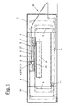
- Figures 1 and 3 show a fleece layer in the top view (1), which is designed as a so-called band layer. He has an upper main carriage in a housing or frame (54) (2) and a lower main carriage (3) and can over it one or more auxiliary wagons or tension wagons (32, 34) exhibit. Above the carriages (2,3,32,34) are means suitable rolls two endless laying tapes (5,6). At least the two main carriages (2, 3) are suitable Drives driven reciprocally. The two Laying tapes (5,6) can also be and variable speed drives.
- a pile generator e.g. one Card or a cardboard-produced fiber pile (7) arrives via a feed belt (25) into the fleece layer (1). He will via a feed path (26) to or on the upper main carriage (2) guided and arrives at the one described in more detail below Tape inlet (4.9) between the two laying tapes (5.6).
- the latter are at least in the area between the two Main carriage (2,3) in a loop parallel to each other and take the pile (7) between them, transport and guide him.
- This loop area is referred to as the outlet section (27). He can extend horizontally or diagonally and the main carriage (2,3) directly or via a fixed redirection (not shown) connect.
- the Outlet line (27) straight.
- the pile (7) emerges downwards and becomes on one transversely continuous take-off belt (8) to form a fleece (23) filed.
- the laying carriage (3) moves over the take-off belt (8) back and forth, causing the pile (8) in several layers one on top of the other across and zigzag to the delivery direction is filed.
- the pile (7) becomes scale-like paneled.
- the laying tapes (5,6) step on the laying carriage (3) again apart and are made in separate loops away from the outside and then to the tape inlet (9) again returned.
- the two main cars (2,3) can form a short Pass line in the same direction as in DE-A-19 27 863 or EP-A-0 517 568 or in opposite directions with stationary Belt deflection as with FR-A-2 553 102 or the WO 91/156018 move.
- To influence the pile placement on the trigger belt (8) can be by means of the auxiliary or Tensioners (32,34) internal storage are formed. It can also be worked with delay when laying the pile, around a certain thickness profile of the fleece (23) adjust.
- the tape inlet (4) movable and is located on the superstructure (2). He has one comparatively short inlet section (9) with a fixed one Length.
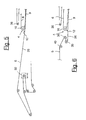
- Figures 3 to 6 show a variant with a stationary belt infeed (4) in front of the uppercarriage (2) is arranged. Here the inlet section (9) is larger and has a variable length.
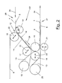
- FIG 2 illustrates the tape inlet (4) of the fleece layer (1) of Figure 1 in detail.
- the belt inlet (4) is located on the upper main carriage (2).
- the two meet behind the Laying trolley (3) again separately guided laying tapes (5,6) together, then run close together and take that from outside pile (7) between them.
- the embodiment shown serves a laying tape (5) at the same time as pile feeder (25) and is made accordingly the housing (54) of the fleece layer (1) led out.
- the Flor (7) lies open on the laying tape (5) and is transported from this to the tape inlet (4).
- the inlet slot (12) has an adjustable width that adapted to the respective requirements of the pile material can be. It is preferably somewhat larger than that Pile thickness, so that the loose pile (7) initially without Squeeze or compression can be included.
- the Width can also be equal to or less than the pile thickness and if necessary already when the pile (7) lead to a clamping in the tape inlet (4).
- the band sections (10,11) run essentially parallel. This can be strictly parallel. The distance of the Alternatively, it can also be determined by the running direction (24) reduce. This will make you look at an acute angle funnel-shaped tapering inlet section (9) formed in the pile (7) is gradually pressed together and clamped is before it reaches the lower deflection (15). At In this variant it can be advantageous to extend the width of the Inlet slot (12) larger than the pile thickness adjust. But it is also possible with a small one Slot width the pile (7) immediately upon entering the Tape inlet (4) to clamp and compression along the length to increase the inlet section (9) even further. The vote the appropriate setting depends on the type of Pile material and possibly also after Pile feed speed and / or other parameters.
- the inlet section (9) or the one forming it Band sections (10,11) are at an obtuse angle ⁇ against the horizontal or the feed or Inlet direction (24) inclined downwards.
- This obtuse angle ⁇ in Fig. 1 refers to the Belt deflection of the laying tape (5) on the deflection roller (14).
- the preferably horizontal feed path (26) of the Laying tape (5) is in the sloping tape section (10) redirected.
- the obtuse angle ⁇ between the band areas is greater than 90 ° and less than 180 °. He is preferably about 135 °.
- the pile (7) and the laying tapes (5,6) again preferably in one redirected horizontal direction and get over the Outlet section (27) to the laying carriage (3).
- the belt inlet (4) finds an overall deflection of the pile (5) or Laying tapes (5.6) instead of 180 °.
- the deflection at its upper end weaker and stronger at the lower end.
- the Belt inlet (4) is the pile (7) in front of the lower stronger one Redirection (15) over a longer straight section already safely guided and covered and does not get through it suddenly to the clamping point on the deflection (15).
- the laying tape (5) is preferably on the top over two Main carriage (2) deflection rollers arranged relatively stationary (14.15).
- the deflection rollers (14, 15) are corresponding to the slope of the inlet section (9) in the Height and laterally spaced.
- the upper deflection roller (16) of the other laying belt (6) is above the opposite deflecting roller (14) arranged.
- the line connecting the two roller axes runs approximately perpendicular to the incline of the inlet section (9).
- the laying tape has at the lower end of the inlet section (9) (6) two or more belt loops (13).
- the one Band loop (13) is located in front of the Deflection roller (15) formed deflection point and the second Band loop (13) behind it. Over the strap loops (13) becomes the one in the tape inlet (9) above or outside Laying tape (6) from the pile (7) at the critical deflection points replaced.
- the replacement will make them different Belt speeds in the area of the deflection avoided.
- the two laying tapes (5,6) move namely with the intervening pile around the axis of the Deflection roller (15).
- the laying tape on top (6) should due to its greater distance from this axis have a higher relative orbital velocity around which The pile (7) is tension-free over the entire deflection area to be able to lead.
- the two tapes (5,6) have the same orbital speed.
- the two Belt loops (13) eliminate the problem.
- the first belt loop (13) is made by deflecting rollers (17,18,19).
- the first deflecting roller (17) sits on lower end of the band section (11) and is above the deflection roller (15). It is arranged so that the connecting line between the two roller axes in approximately perpendicular to the inclination of the inlet slot (12) is aligned.
- the laying tape (6) or its overhead Band section (11) is approximately at one point detached from the pile (7) on which the one below Band section (10) on the deflecting roller (15). Of the The pile (7) arrives in the deflection area without distortion the roller (15).
- the laying tape (6) Via the deflection roller (19), which is offset obliquely to the rear the laying tape (6) is pulled out to the tape loop (13) and then returned to the guide roller (18).
- Latter is essentially at the same level as the Deflection roller (15) and has approximately the same diameter.
- the two laying tapes (5,6) come in approximately Axle height of the two rollers (15, 18) together again and can lead the pile (7) between them. You have with you essentially the same running speed that too is equal to the pile speed.
- the second belt loop is located behind the deflection roller (18) (13) by a laterally offset deflection roller (20) is pulled out.
- Their diameter is such that the laying tape (6) into a horizontal and deflected section parallel to the laying tape (5) becomes.
- this subsequent horizontal section the two tapes (5,6) so close together that they guide the pile (7) between them on both sides.
- a support device e.g. a support roller (21) for the laying tape (6) is arranged be.
- the support roller (21) affects the distance of the Laying tapes (5,6).
- the pile (7) in the Area of the lower deflection on the deflection roller (15) three places between the tapes (5,6) or clamped and therefore reliable and with the same Belt speeds led.
- the guide extends between the belt sections (10,11) just until the lower deflection roller is reached (15).
- the third management point is at the end of the redirection between the deflecting roller (15) and the preferably vertical support roller (21). At this The tape (5) leaves the guide roller again (15).
- the belt inlet (4) and the inlet section (9) are adjustable.
- the position of the delivery devices (22) can be changed.
- the infeed direction is preferably in the region of the inlet slot (12) located deflection rollers (16,17) essentially perpendicular to the direction of the Inlet section (9). This allows the width of the Inlet slot (12) and possibly also the funnel-shaped narrowing of the inlet section (9) changed become.
- the laying tapes (5, 6) can be permeable to air, so that due to the increasing narrowing of the inlet section (9) the pile pressed together with the air it contains is pushed out.
- the deflecting roller (18) is preferably horizontal adjustable and can be compared to the deflection roller (15) of the laying tape (5) can be approximated or removed. This will make the second leading point for the pile (7) influenced in the lower deflection area.
- the support roller (21) is vertically adjustable and can thereby also opposite the deflecting roller (15) be approximated or removed. With the backup roller (21) becomes the pile guide on said third Leadership influenced.
- the two begin the pile (7) receiving tape sections (10,11) approximately at the same height at the entrance of the inlet slot (12).
- the overhead band section (11) also pulled a little higher be and if necessary via the deflection point on the roller (14) protrude. This is e.g. to catch a very fast running pile cheap.
- the band section (11) but can also be arranged a little lower.
- the training, number and arrangement can also be changed the belt loops (13) at the lower end of the inlet section (9). For example, only one lower strap loop (13) to be available.
- the Inlet section (9) can also be somewhat curved.
- the fleece layer (1) has a separate embodiment Feed belt (25) over which the pile (7) of a arranged in front of it with a uniform but variable speed is supplied.
- the Fleece layer (1) is in turn equipped with four carriages, namely with an uppercarriage (2), a laying carriage (3) and one tensioning carriage (32,34) for each laying tape (5,6).
- the first laying tape (5) takes over in the area of Feed section (26) the pile (7) from the feed belt (25) and guides the pile (7) into a stationary one Tape inlet (4) between the two laying tapes (5,6), the up to the superstructure (2) and the deflection there (15) extends.
- the stationary belt inlet (4) is nearby the end of the path of movement of the superstructure (2) approximately in the middle of the laying width of the fleece layer (1).
- the laying tape (5) is the lower laying tape for the tape inlet (4) fed while the upper laying tape (6) over a Deflection roller (16) is fed.
- the stationary guide roller (16) has a Compared to the other deflecting rollers considerably larger Diameter on, whereby at the tape inlet (4) Inlet funnel is formed.
- the laying tapes (5,6) point at the belt inlet (4) e.g. a distance that is larger than the pile thickness.
- the inlet slot (12) thus formed enables the tape (7) to be fed in initially without substantial clamping or compression.
- Below the lower laying tape (5) is one in height adjustable support device (21) with which the gap width of the inlet slot (12) can be adjusted.
- the inlet slot (12) and the superstructure (2) extends the essentially straight inlet section (9), in which the tape sections (10,11) of the laying tapes (5,6) gradually converge so that they at the end of the inlet section (9) at the latest on the superstructure (2) have a distance that is adapted to the pile thickness.
- This distance can be, for example, the pile thickness correspond or to a fixed value, e.g. 15 mm, be set.
- the funnel-shaped narrowing Inlet section (9) gradually becomes the pile (7) guided and covered on both sides. This can done without compression. Alternatively, the pile (7) in the inlet section (9) also gradually compressed and be clamped.
- the inlet section (9) changes with the Movement of the superstructure (2) their length.
- the upper laying tape (6) as in above-described embodiment of a Guide roller (17) and on the rollers (18,19,20) below Formation of two ribbon loops (13) deflected several times, see above that the pile (7) in the deflection area on the superstructure (2) is not runs between the two laying tapes (5,6).
- the pile (7) is again between the two tapes (5,6).
- the one between the upper carriage (2) and the laying carriage (3) Outlet section (27) preferably runs in a straight line, the pile (7) after further deflection by 90 ° in the Laying carriage (3) exits at an exit point and from the floating laying carriage (3) on the Discharge belt (8) is deposited.
- the laying carriage (3) points also a guide roller (56) for the laying tape (5) after double deflection via the deflection rollers (60.62) again via further deflection rollers to the Tape inlet (4) is returned.
- the laying tape (6) will deflected via a deflection roller (58) and back to the Belt inlet (4) returned.
- the inlet section (9) and / or the outlet section (27) preferably run at an obtuse angle ⁇ to Horizontal in the direction of movement (24) of the laying tapes (5,6) diagonally downwards.
- This angle is as in the first Embodiment of Figures 1 and 2 between 90 ° and 180 ° and is e.g. approx. 170 °.
- a tension carriage (32) is provided for the laying tape (5), depending on the movement of the laying carriage (3) is controlled.
- a tension carriage is for the laying tape (6) (34) provided, depending on the movement of the Upper carriage (2) and the laying carriage (3) is controlled. The movement of the tensioning carriage (34) with the help of Toothed belt positively controlled.
- the tensioning carriage (34) is in the direction of rotation of the laying tape (6) behind a stationary deflection roller (36) and the further stationary deflection roller (16) at the belt inlet (4) arranged.
- Figure 4 shows the tape inlet (4) with an enlarged Scale, one from a perforated or screen roller existing pressure roller (30) the pile (7) before Pre-compress inlet slot (12).
- the pressure roller (30) can be at a predetermined distance from the lower one Laying tape (5) are held.
- FIG. 5 shows an alternative embodiment, at which the lower laying tape (5) in the inlet section (9) also serves as a feed belt (25).
- One before Leading section (9) in front of the belt inlet (4) Feed path (26) is in the same plane as that Inlet section (9) and is in relation to the horizontal Direction of movement of the laying tape (5) inclined downwards.
- Figure 6 shows a further embodiment in which the lower laying belt (5) also serves as a feed belt (25) serves.
- the laying tape (5) over the Deflection rollers (38 to 40) deflected several times, so that Laying tape (5) to form the inlet slot (12) Distance from the laying tape (6) of the inlet section (9) can be supplied.
- the deflection roller (39) can be adjusted in height be.
Landscapes
- Engineering & Computer Science (AREA)
- Textile Engineering (AREA)
- Preliminary Treatment Of Fibers (AREA)
- Nonwoven Fabrics (AREA)
- Cosmetics (AREA)
- Treatment Of Fiber Materials (AREA)
- Auxiliary Devices For And Details Of Packaging Control (AREA)
Description
Beim erfindungsgemäßen Bandeinlauf ist wie beim Stand der Technik eine schräg abwärts geneigte Einlaufstrecke vorhanden, die im Gegensatz zum Stand der Technik aber von zwei nahe beieinander laufenden Bandabschnitten gebildet wird. Die Bandabschnitte bilden beim Eintritt in den Bandeinlauf zwischen ihren benachbarten Umlenkwalzen einen schmalen Einlaufschlitz, der an die Flordicke angepaßt ist. In der anschließenden Einlaufstrecke nehmen die beiden Bandabschnitte den zugeführten Flor auf und führen ihn beidseitig und/oder decken ihn ab.
- Figur 1:
- eine Übersichtsdarstellung eines Vlieslegers mit einem bewegten Bandeinlauf am Legewagen,
- Figur 2:
- eine vergrößerte und detaillierte Detailansicht des Bandeinlaufs von Fig. 1,
- Figur 3:
- eine Übersichtsdarstellung eines Vlieslegers in Variation zu Fig. 1 mit einem stationären Bandeinlauf,
- Figur 4:
- eine Detaildarstellung des Bandeinlaufs von Fig. 3 mit einer vorgelagerten Andrückwalze,
- Figur 5:
- ein alternatives Ausführungsbeispiel des Bandeinlaufs von Fig. 4, bei dem das untere Legeband zugleich das Zuführungsband ist, und
- Figur 6:
- ein weiteres alternatives Ausführungsbeispiel zu Fig. 4 und 5, bei dem das untere Legeband zugleich das Zuführungsband ist.
- 1
- Vliesleger
- 2
- Hauptwagen, Oberwagen
- 3
- Hauptwagen, Legewagen
- 4
- Bandeinlauf
- 5
- Legeband, Zuführband
- 6
- Legeband, Gegenband
- 7
- Flor
- 8
- Abzugsband
- 9
- Einlaufstrecke
- 10
- Bandabschnitt
- 11
- Bandabschnitt
- 12
- Einlaufschlitz, Einlauftrichter
- 13
- Bandschlaufe
- 14
- Umlenkwalze, Zuführband
- 15
- Umlenkwalze, Zuführband
- 16
- Umlenkwalze, Gegenband
- 17
- Umlenkwalze, Gegenband
- 18
- Umlenkwalze, Gegenband
- 19
- Umlenkwalze, Bandschlaufe
- 20
- Umlenkwalze, Bandschlaufe
- 21
- Stützeinrichtung, Stützwalze
- 22
- Zustelleinrichtung
- 23
- Vlies
- 24
- Laufrichtung
- 25
- Zuführband
- 26
- Zuführstrecke
- 27
- Auslaufstrecke
- 30
- Andruckwalze
- 32
- Spannwagen, Hilfswagen
- 34
- Spannwagen, Hilfswagen
- 36
- Umlenkwalze
- 38
- Umlenkwalze
- 39
- Umlenkwalze
- 40
- Umlenkwalze
- 42
- Umlenkwalze
- 54
- Gestell
- 56
- Führungswalze
- 58
- Umlenkwalze
- 60
- Umlenkwalze
- 62
- Umlenkwalze
Claims (22)
- Vliesleger mit mehreren relativ zueinander beweglichen Wagen (2,3) und mehreren Legebändern (5,6), zwischen denen der Flor (7) aufgenommen und zumindest bereichsweise geführt ist, wobei der Vliesleger (1) eingangsseitig für die Floraufnahme einen Bandeinlauf (4) der Legebänder (5,6) aufweist, wobei der Bandeinlauf (4) eine schräg abwärts geneigte Einlaufstrecke (9) mit zwei benachbart laufenden Bandabschnitten (10,11) aufweist, dadurch gekennzeichnet, daß die am Eintritt in den Bandeinlauf (4) zusammengeführten Bandabschnitte (10,11) einen an die Flordicke angepaßten schmalen Einlaufschlitz (12) bilden und in der Einlaufstrecke (9) im wesentlichen parallel oder im spitzen Winkel und so nahe beieinander laufen, daß sie den Flor (7) in der Einlaufstrecke (9) beidseitig führen oder abdecken.
- Vliesleger nach Anspruch 1, dadurch gekennzeichnet, daß die Einlaufstrecke (9) sich trichterförmig verengt, wobei der Flor (7) in der Einlaufstrecke (9) vor Erreichen der unteren Bandumlenkung (15) allmählich zusammengepreßt und geklemmt wird.
- Vliesleger nach Anspruch 1 oder 2, dadurch gekennzeichnet, daß die Einlaufstrecke (9) und/oder ihr Einlaufschlitz (12) eine verstellbarer Weite aufweisen.
- Vliesleger nach Anspruch 1, 2 oder 3, dadurch gekennzeichnet, daß die Weite des Einlaufschlitzes (12) größer als die Flordicke ist.
- Vliesleger nach einem der Ansprüche 1 bis 4, dadurch gekennzeichnet, daß der Flor (7) in der Einlaufstrecke (9) kompressionsfrei geführt ist.
- Vliesleger nach einem der Ansprüche 1 bis 4, dadurch gekennzeichnet, daß der Flor (7) in der Einlaufstrecke (9) mit allmählich zunehmender Kompression oder Klemmung geführt ist.
- Vliesleger nach Anspruch 1 oder einem der folgenden, dadurch gekennzeichnet, daß der Bandeinlauf (4) am Oberwagen (2) angeordnet ist.
- Vliesleger nach einem der Ansprüche 1 bis 6, dadurch gekennzeichnet, daß der Bandeinlauf (4) stationär vor dem Oberwagen (2) angeordnet ist.
- Vliesleger nach Anspruch 1 oder einem der folgenden, dadurch gekennzeichnet, daß die Bandabschnitte (10,11) im wesentlichen gerade verlaufen.
- Vliesleger nach Anspruch 1 oder einem der folgenden, dadurch gekennzeichnet, daß die Einlaufstrecke (9) und/oder die Auslaufstrecke (27) in einem stumpfen Winkel β gegen die Horizontale und/oder die Zuführrichtung (24) schräg abwärts gerichtet ist.
- Vliesleger nach Anspruch 1 oder einem der folgenden, dadurch gekennzeichnet, daß das eine Legeband (5) als Zuführband (25) für den Transport des Flors (7) zum Bandeinlauf (9) ausgebildet ist.
- Vliesleger nach Anspruch 7 oder einem der folgenden, dadurch gekennzeichnet, daß die Bandabschnitte (10,11) an der oberen Bandumlenkung (14) etwa in gleicher Höhe beginnen.
- Vliesleger nach Anspruch 3 oder einem der folgenden, dadurch gekennzeichnet, daß zumindest ein Bandabschnitt (10,11) an den Flor (7) zustellbar angeordnet ist.
- Vliesleger nach Anspruch 1 oder einem der folgenden, dadurch gekennzeichnet, daß an den Enden der Bandabschnitten (10,11) Umlenkwalzen (14,15,16,17,18) angeordnet sind.
- Vliesleger nach Anspruch 1 oder einem der folgenden, dadurch gekennzeichnet, daß der obenliegende Bandabschnitt (11) am unteren Ende der Einlaufstrecke (9) mindestens eine Bandschlaufe (13) aufweist.
- Vliesleger nach Anspruch 1 oder einem der folgenden, dadurch gekennzeichnet, daß am unteren Ende der Einlaufstrecke (9) zwei Umlenkwalzen (15,18) einander horizontal gegenüberliegen, wobei der obenliegende Bandabschnitt (11) vor seiner Umlenkwalze (18) eine Bandschlaufe (13) aufweist.
- Vliesleger nach Anspruch 7 oder einem der folgenden, dadurch gekennzeichnet, daß unterhalb der unteren Umlenkwalze (15) des zuführenden Legebands (5) eine Stützeinrichtung (21) angeordnet ist.
- Vliesleger Anspruch 14 oder einem der folgenden, dadurch gekennzeichnet, daß zumindest eine der Umlenkwalzen (14,15,16,17,18) und/oder die Stützeinrichtung (21) eine Zustelleinrichtung (22) aufweisen.
- Vliesleger nach Anspruch 1 oder einem der folgenden, dadurch gekennzeichnet, daß vor dem Bandeinlauf (4) eine auf den Flor (7) einwirkende Andrückwalze, vorzugsweise eine Siebwalze (30), angeordnet ist.
- Verfahren zum Herstellen eines Vlieses durch Aufnehmen eines auf einem Legeband einlaufenden Flores (7) zwischen zwei endlos umlaufenden Legebändern (5,6) in einem Bandeinlauf (4) eines Vlieslegers (1), durch Transportieren des Flores (7) zwischen den Legebändern (5,6) über eine schräg abwärts Einlaufstrecke (9) zu einem in Richtung des einlaufenden Flores (7) hin- und herfahrbaren, die Legebänder (5,6) umlenkenden Oberwagen (2) und von dem Oberwagen (2) zu einem über die gesamte Legebreite hin- und herfahrbaren, ebenfalls die Legebänder (5,6) umlenkenden Legewagen (3), und durch Ablegen des Flores (7) durch den Legewagen (3) auf eine Abführungseinrichtung (8), dadurch gekennzeichnet, daß der bei hoher Einlaufgeschwindigkeit in den Bandeinlauf (4) einlaufende Flor (7) über einen auf die Fordicke angepaßten Einlaufschlitz (12) in die Einlaufstrecke (9) geführt und dort zum sukzessiven Entfernen der überschüssigen, mit dem Flor (7) transportierten Luft zwischen zwei im wesentlichen parallel oder spitzwinklig und nahe beieinander laufenden Bandabschnitten (10,11) der Legebänder (5,6) aufgenommen wird.
- Verfahren nach Anspruch 20, dadurch gekennzeichnet, daß der Abstand der Legebänder (5,6) am Ende der Einlaufstrecke (9) an die Flordicke angepaßt wird.
- Verfahren nach Anspruch 20 oder 21, dadurch gekennzeichnet, daß der Abstand der Legebänder (5,6) am Ende der Einlaufstecke (9) bis auf die Flordicke reduziert wird.
Applications Claiming Priority (3)
| Application Number | Priority Date | Filing Date | Title |
|---|---|---|---|
| DE29518587U | 1995-11-23 | ||
| DE29518587U DE29518587U1 (de) | 1995-11-23 | 1995-11-23 | Vliesleger |
| PCT/EP1996/005154 WO1997019209A1 (de) | 1995-11-23 | 1996-11-22 | Vliesleger |
Publications (2)
| Publication Number | Publication Date |
|---|---|
| EP0865521A1 EP0865521A1 (de) | 1998-09-23 |
| EP0865521B1 true EP0865521B1 (de) | 1999-09-15 |
Family
ID=8015819
Family Applications (1)
| Application Number | Title | Priority Date | Filing Date |
|---|---|---|---|
| EP96939893A Expired - Lifetime EP0865521B1 (de) | 1995-11-23 | 1996-11-22 | Vliesleger |
Country Status (6)
| Country | Link |
|---|---|
| US (1) | US6085391A (de) |
| EP (1) | EP0865521B1 (de) |
| JP (1) | JP2000501457A (de) |
| DE (2) | DE29518587U1 (de) |
| ES (1) | ES2136440T3 (de) |
| WO (1) | WO1997019209A1 (de) |
Cited By (9)
| Publication number | Priority date | Publication date | Assignee | Title |
|---|---|---|---|---|
| EP1717357A1 (de) | 2005-04-27 | 2006-11-02 | Oskar Dilo Maschinenfabrik KG | Vliesleger |
| EP1816243A1 (de) | 2006-02-01 | 2007-08-08 | Oskar Dilo Maschinenfabrik KG | Vorrichtung zum Legen eines Vlieses |
| EP1975287A1 (de) * | 2007-03-30 | 2008-10-01 | Oskar Dilo Maschinenfabrik KG | Vliesleger |
| EP1975286A1 (de) * | 2007-03-30 | 2008-10-01 | Oskar Dilo Maschinenfabrik KG | Vliesleger |
| EP2157216A1 (de) * | 2008-08-21 | 2010-02-24 | Oskar Dilo Maschinenfabrik KG | Vorrichtung zum Legen eines Vlieses |
| DE102010050027A1 (de) | 2010-11-02 | 2012-05-03 | Trützschler Nonwovens Gmbh | Kreuzleger |
| DE102010050028A1 (de) | 2010-11-02 | 2012-05-03 | Trützschler Nonwovens Gmbh | Vliesbandleger |
| DE102010050029A1 (de) | 2010-11-02 | 2012-05-03 | Trützschler Nonwovens Gmbh | Kreuzleger |
| DE202014100908U1 (de) | 2014-02-27 | 2015-05-28 | Autefa Solutions Germany Gmbh | Kardiereinrichtung |
Families Citing this family (16)
| Publication number | Priority date | Publication date | Assignee | Title |
|---|---|---|---|---|
| DE29822460U1 (de) * | 1998-12-18 | 2000-05-18 | Autefa Maschinenfabrik GmbH, 86316 Friedberg | Vliesleger |
| DE29822461U1 (de) * | 1998-12-18 | 2000-05-18 | Autefa Maschinenfabrik GmbH, 86316 Friedberg | Vliesleger |
| FR2791364B1 (fr) * | 1999-03-23 | 2001-06-08 | Asselin | Etaleur-nappeur |
| DE29909016U1 (de) * | 1999-05-26 | 2000-10-05 | Autefa Maschinenfabrik GmbH, 86316 Friedberg | Vliesanlage |
| DE20211365U1 (de) | 2002-07-27 | 2003-10-09 | AUTEFA Automation GmbH, 86316 Friedberg | Vorrichtung zur Faserbehandlung |
| DE10250089B4 (de) * | 2002-10-25 | 2014-02-13 | Oskar Dilo Maschinenfabrik Kg | Steilarm-Vliesleger und Vorrichtung zum Erzeugen eines kreuzgelegten Faservlieses |
| DE202004020165U1 (de) * | 2004-12-23 | 2006-05-04 | Autefa Automation Gmbh | Vliesleger |
| DE102004063401A1 (de) * | 2004-12-23 | 2006-07-20 | Autefa Automation Gmbh | Vliesleger und Verfahren zum Führen eines Flors |
| DE102006028448A1 (de) * | 2006-06-21 | 2007-12-27 | ERKO Trützschler GmbH | Kreuzleger |
| DE502007003464D1 (de) * | 2007-02-15 | 2010-05-27 | Dilo Kg Maschf Oskar | Vorrichtung zum Legen eines Vlieses |
| EP2479330B1 (de) * | 2011-01-19 | 2013-12-18 | Oskar Dilo Maschinenfabrik KG | Vliesleger |
| EP2479321A1 (de) * | 2011-01-19 | 2012-07-25 | Oskar Dilo Maschinenfabrik KG | Vliesleger |
| DE202012102597U1 (de) * | 2012-07-13 | 2013-10-14 | Hi Tech Textile Holding Gmbh | Vliesleger |
| DE102012019363A1 (de) * | 2012-10-02 | 2014-04-03 | Trützschler GmbH & Co Kommanditgesellschaft | Kreuzleger und Verfahren zum Betreiben eines Kreuzlegers |
| EP3239371B1 (de) | 2016-04-29 | 2021-06-23 | Oskar Dilo Maschinenfabrik KG | Vliesleger |
| IT201900008706A1 (it) * | 2019-06-12 | 2020-12-12 | Mirco Battistella | Faldatore per veli di carda |
Family Cites Families (10)
| Publication number | Priority date | Publication date | Assignee | Title |
|---|---|---|---|---|
| DE75059C (de) * | Firma FRIED. KRUPP GRUSONWERK in Magdeburg-Buckau | Glockenmühle mit abnehmbarem Rumpf | ||
| US2387150A (en) * | 1940-09-26 | 1945-10-16 | Rudolf F Hlavaty | Material handling apparatus |
| SE322153B (de) * | 1968-06-07 | 1970-03-23 | Nordiska Maskinfilt Ab | |
| FR2234395B1 (de) * | 1973-06-19 | 1976-09-17 | Asselin Robert | |
| FR2553102B1 (fr) * | 1983-10-07 | 1986-01-31 | Asselin Ets | Etaleur-nappeur |
| US4830351A (en) * | 1988-01-27 | 1989-05-16 | Morrison Berkshire, Inc. | Batt stabilization in cross-lapped web manufacturing apparatus |
| DE4010174A1 (de) * | 1990-03-30 | 1991-10-02 | Hollingsworth Gmbh | Verfahren zum ablegen eines vlieses oder dgl., sowie vliesbandleger |
| FR2677044B1 (fr) * | 1991-06-03 | 1994-04-29 | Asselin Ets | Etaleur-nappeur. |
| FR2677046B1 (fr) * | 1991-06-03 | 1995-01-13 | Asselin Ets | Etaleur-nappeur. |
| JP3118102B2 (ja) * | 1992-12-18 | 2000-12-18 | 株式会社ユメロン黒川 | 布団綿の製造方法 |
-
1995
- 1995-11-23 DE DE29518587U patent/DE29518587U1/de not_active Expired - Lifetime
-
1996
- 1996-11-22 JP JP9519401A patent/JP2000501457A/ja active Pending
- 1996-11-22 WO PCT/EP1996/005154 patent/WO1997019209A1/de not_active Ceased
- 1996-11-22 DE DE59603109T patent/DE59603109D1/de not_active Expired - Lifetime
- 1996-11-22 EP EP96939893A patent/EP0865521B1/de not_active Expired - Lifetime
- 1996-11-22 ES ES96939893T patent/ES2136440T3/es not_active Expired - Lifetime
- 1996-11-22 US US09/068,652 patent/US6085391A/en not_active Expired - Lifetime
Cited By (14)
| Publication number | Priority date | Publication date | Assignee | Title |
|---|---|---|---|---|
| EP1717357A1 (de) | 2005-04-27 | 2006-11-02 | Oskar Dilo Maschinenfabrik KG | Vliesleger |
| EP1816243A1 (de) | 2006-02-01 | 2007-08-08 | Oskar Dilo Maschinenfabrik KG | Vorrichtung zum Legen eines Vlieses |
| EP1975287A1 (de) * | 2007-03-30 | 2008-10-01 | Oskar Dilo Maschinenfabrik KG | Vliesleger |
| EP1975286A1 (de) * | 2007-03-30 | 2008-10-01 | Oskar Dilo Maschinenfabrik KG | Vliesleger |
| EP2157216A1 (de) * | 2008-08-21 | 2010-02-24 | Oskar Dilo Maschinenfabrik KG | Vorrichtung zum Legen eines Vlieses |
| CN101654848B (zh) * | 2008-08-21 | 2011-08-10 | 奥斯卡迪罗机械制造公司 | 纤维铺设装置 |
| DE102010050027A1 (de) | 2010-11-02 | 2012-05-03 | Trützschler Nonwovens Gmbh | Kreuzleger |
| DE102010050028A1 (de) | 2010-11-02 | 2012-05-03 | Trützschler Nonwovens Gmbh | Vliesbandleger |
| DE102010050029A1 (de) | 2010-11-02 | 2012-05-03 | Trützschler Nonwovens Gmbh | Kreuzleger |
| WO2012059273A1 (de) | 2010-11-02 | 2012-05-10 | Trützschler Nonwovens Gmbh | Vliesbandleger und verfahren zum bilden eines vlieses |
| WO2012059271A1 (de) | 2010-11-02 | 2012-05-10 | Trützschler Nonwovens Gmbh | Kreuzleger |
| DE202014100908U1 (de) | 2014-02-27 | 2015-05-28 | Autefa Solutions Germany Gmbh | Kardiereinrichtung |
| WO2015128391A1 (de) | 2014-02-27 | 2015-09-03 | Autefa Solutions Germany Gmbh | Kardiereinrichtung und kardierverfahren |
| US10443155B2 (en) | 2014-02-27 | 2019-10-15 | Autefa Solutions Germany Gmbh | Carding apparatus and carding method |
Also Published As
| Publication number | Publication date |
|---|---|
| DE29518587U1 (de) | 1997-04-10 |
| EP0865521A1 (de) | 1998-09-23 |
| JP2000501457A (ja) | 2000-02-08 |
| WO1997019209A1 (de) | 1997-05-29 |
| US6085391A (en) | 2000-07-11 |
| ES2136440T3 (es) | 1999-11-16 |
| DE59603109D1 (de) | 1999-10-21 |
Similar Documents
| Publication | Publication Date | Title |
|---|---|---|
| EP0865521B1 (de) | Vliesleger | |
| DE2954326C2 (de) | Vorrichtung zum offenend-spinnen eines fadens | |
| EP0659220B1 (de) | Vorrichtung zur herstellung eines vlieses aus fasermaterial | |
| DE69409648T3 (de) | Dispositif pour detacher et transporter à grande vitesse un voile fibreux en sortie de carde | |
| EP1870499B1 (de) | Kreuzleger | |
| EP2157216B1 (de) | Vorrichtung zum Legen eines Vlieses | |
| EP1381721B1 (de) | Verfahren zum profilieren eines vlieses und profilbildungseinrichtung | |
| EP1975287A1 (de) | Vliesleger | |
| CH694055A5 (de) | Vorrichtung an einer Strecke zur Verarbeitung eines Faserverbandes aus Faserbändern. | |
| EP1828453B1 (de) | Vliesleger und verfahren zum führen eines flors | |
| DE3804147C2 (de) | ||
| DE19543623A1 (de) | Florleger, sowie Verfahren zum Herstellen eines Vlieses | |
| DE10146907A1 (de) | Vlieszuführvorrichtung | |
| DE2711619C3 (de) | Vorrichtung an einer Karde zum Abnehmen und Zusammenfassen eines aus einem Lieferwerk einer Karde austretenden Faserflors | |
| DE4228827C2 (de) | Verfahren und Vorrichtung zum Verdichten eines diskontinuierlich durch Löten von Kammzügen gebildeten Vlieses | |
| DE102004063401A1 (de) | Vliesleger und Verfahren zum Führen eines Flors | |
| EP3447175B1 (de) | Vliesleger und vlieslegeverfahren | |
| DE2846517A1 (de) | Verfahren und vorrichtung zum legen einer orientierten faserbahn | |
| DE3834039A1 (de) | Querbandanordnung am ausgang einer karde | |
| DE602005006163T2 (de) | Kämmmaschine für Baumwolle und dergleichen mit verbesserter Vorrichtung zur Faserbandformung | |
| DE1290853B (de) | Anlage zum Speisen einer Kardengruppe | |
| EP3543386B1 (de) | Bandbildungseinheit für eine karde | |
| DE4234355A1 (de) | Verfahren und Vorrichtung zum Herstellen einer Filzbahn großer Breite | |
| DE2341314A1 (de) | Vorrichtung zur faserfuehrung bei streckwerken fuer textilfasern | |
| DE3428705A1 (de) | Vorrichtung zum friktionsspinnen |
Legal Events
| Date | Code | Title | Description |
|---|---|---|---|
| PUAI | Public reference made under article 153(3) epc to a published international application that has entered the european phase |
Free format text: ORIGINAL CODE: 0009012 |
|
| 17P | Request for examination filed |
Effective date: 19980328 |
|
| AK | Designated contracting states |
Kind code of ref document: A1 Designated state(s): DE ES FR GB IT |
|
| GRAG | Despatch of communication of intention to grant |
Free format text: ORIGINAL CODE: EPIDOS AGRA |
|
| 17Q | First examination report despatched |
Effective date: 19981105 |
|
| GRAG | Despatch of communication of intention to grant |
Free format text: ORIGINAL CODE: EPIDOS AGRA |
|
| GRAG | Despatch of communication of intention to grant |
Free format text: ORIGINAL CODE: EPIDOS AGRA |
|
| GRAH | Despatch of communication of intention to grant a patent |
Free format text: ORIGINAL CODE: EPIDOS IGRA |
|
| GRAH | Despatch of communication of intention to grant a patent |
Free format text: ORIGINAL CODE: EPIDOS IGRA |
|
| GRAA | (expected) grant |
Free format text: ORIGINAL CODE: 0009210 |
|
| AK | Designated contracting states |
Kind code of ref document: B1 Designated state(s): DE ES FR GB IT |
|
| GBT | Gb: translation of ep patent filed (gb section 77(6)(a)/1977) |
Effective date: 19990924 |
|
| REF | Corresponds to: |
Ref document number: 59603109 Country of ref document: DE Date of ref document: 19991021 |
|
| ET | Fr: translation filed | ||
| REG | Reference to a national code |
Ref country code: ES Ref legal event code: FG2A Ref document number: 2136440 Country of ref document: ES Kind code of ref document: T3 |
|
| ITF | It: translation for a ep patent filed | ||
| PLBE | No opposition filed within time limit |
Free format text: ORIGINAL CODE: 0009261 |
|
| STAA | Information on the status of an ep patent application or granted ep patent |
Free format text: STATUS: NO OPPOSITION FILED WITHIN TIME LIMIT |
|
| 26N | No opposition filed | ||
| REG | Reference to a national code |
Ref country code: GB Ref legal event code: IF02 |
|
| PGFP | Annual fee paid to national office [announced via postgrant information from national office to epo] |
Ref country code: ES Payment date: 20101123 Year of fee payment: 15 |
|
| REG | Reference to a national code |
Ref country code: ES Ref legal event code: FD2A Effective date: 20130603 |
|
| PG25 | Lapsed in a contracting state [announced via postgrant information from national office to epo] |
Ref country code: ES Free format text: LAPSE BECAUSE OF NON-PAYMENT OF DUE FEES Effective date: 20111123 |
|
| PGFP | Annual fee paid to national office [announced via postgrant information from national office to epo] |
Ref country code: GB Payment date: 20141120 Year of fee payment: 19 |
|
| REG | Reference to a national code |
Ref country code: FR Ref legal event code: PLFP Year of fee payment: 20 |
|
| PGFP | Annual fee paid to national office [announced via postgrant information from national office to epo] |
Ref country code: DE Payment date: 20151104 Year of fee payment: 20 Ref country code: IT Payment date: 20151124 Year of fee payment: 20 |
|
| PGFP | Annual fee paid to national office [announced via postgrant information from national office to epo] |
Ref country code: FR Payment date: 20151124 Year of fee payment: 20 |
|
| GBPC | Gb: european patent ceased through non-payment of renewal fee |
Effective date: 20151122 |
|
| PG25 | Lapsed in a contracting state [announced via postgrant information from national office to epo] |
Ref country code: GB Free format text: LAPSE BECAUSE OF NON-PAYMENT OF DUE FEES Effective date: 20151122 |
|
| REG | Reference to a national code |
Ref country code: DE Ref legal event code: R071 Ref document number: 59603109 Country of ref document: DE |