EP0865521B1 - Matting device - Google Patents
Matting device Download PDFInfo
- Publication number
- EP0865521B1 EP0865521B1 EP96939893A EP96939893A EP0865521B1 EP 0865521 B1 EP0865521 B1 EP 0865521B1 EP 96939893 A EP96939893 A EP 96939893A EP 96939893 A EP96939893 A EP 96939893A EP 0865521 B1 EP0865521 B1 EP 0865521B1
- Authority
- EP
- European Patent Office
- Prior art keywords
- belt
- inlet
- layering
- web
- nonwoven
- Prior art date
- Legal status (The legal status is an assumption and is not a legal conclusion. Google has not performed a legal analysis and makes no representation as to the accuracy of the status listed.)
- Expired - Lifetime
Links
- 230000006835 compression Effects 0.000 claims description 6
- 238000007906 compression Methods 0.000 claims description 6
- 238000011144 upstream manufacturing Methods 0.000 claims description 5
- 230000001154 acute effect Effects 0.000 claims description 3
- 238000000034 method Methods 0.000 claims 2
- 238000000151 deposition Methods 0.000 claims 1
- 238000004519 manufacturing process Methods 0.000 claims 1
- 238000013461 design Methods 0.000 description 3
- 230000015572 biosynthetic process Effects 0.000 description 2
- 239000000835 fiber Substances 0.000 description 2
- 239000000463 material Substances 0.000 description 2
- 238000012549 training Methods 0.000 description 2
- 238000009960 carding Methods 0.000 description 1
- 238000011161 development Methods 0.000 description 1
- 230000018109 developmental process Effects 0.000 description 1
- 230000000694 effects Effects 0.000 description 1
- 238000007726 management method Methods 0.000 description 1
- 238000012545 processing Methods 0.000 description 1
- 238000012546 transfer Methods 0.000 description 1
Images

Classifications
-
- D—TEXTILES; PAPER
- D01—NATURAL OR MAN-MADE THREADS OR FIBRES; SPINNING
- D01G—PRELIMINARY TREATMENT OF FIBRES, e.g. FOR SPINNING
- D01G25/00—Lap-forming devices not integral with machines specified above
Definitions
- the invention relates to a nonwoven layer with the features in the preamble of procedural and Device main claims.
- Such a fleece layer is known from EP-0 609 907 A2 known.
- the trained as a so-called band layer Fleece layer has two relatively movable Main carriage and two endless and looped all-round driven laying tapes.
- the tapes are running parallel at least in the section between the main carriages, taking up and guiding the pile between them.
- the fleece layer on the input side has a pile pick-up a so-called tape infeed of the laying tapes. That of two Side tapes come together here and form an inlet section with an opening angle of the tapes of at least 20 °.
- the inlet slot on The entrance to the inlet section is therefore very large and much wider than the pile thickness.
- the one Laying tape fed pile is in the tape infeed with a obtuse angles obliquely downwards against the horizontal redirected. Due to the large opening angle and the wide Inlet slit, the pile is open in the inlet section and is only at the bottom between the two adjacent pulleys between the laying tapes clamped and guided on both sides.
- the pile can be in the Inlet section at high speeds from the bottom Lift off the tape. This can be especially the case with sensitive Lead to faults. In this arrangement, the Feed speed limited.
- FR-2 553 102 shows another nonwoven layer.
- the two laying tapes have two parallel juxtaposed and straight belt sections that are extend vertically downwards, making the horizontal fed pile at the belt inlet a deflection of 90 ° experiences.
- such Belt infeed also only for limited Feed speeds of the pile and Working speeds of the fleece layer can be used. If the feed speeds get too high, it can to demolish in the very light and highly sensitive Fiber pile come.
- WO 91/15618 shows a further variant of the Belt infeed, in which both laying tapes over the main carriage two large deflection rollers are guided. This forms there is also another inlet funnel for one Placing tape fed pile.
- the two large deflection rollers are horizontally next to each other at about the same height arranged, whereby the pile only about at midpoint of the two rollers by the ones that come close together here Laying tapes are recorded and guided on both sides. Before and then the tapes pass through the roller shape apart again.
- These two aforementioned fleece layers are for higher feed speeds of the pile and Processing speeds of the fleece layer designed.
- the tape inlet according to the invention as in the prior art, there is an inclined downward sloping inlet section, which, in contrast to the prior art, is formed by two tape sections running close to one another.
- the belt sections form a narrow inlet slot between their adjacent deflecting rollers when they enter the belt inlet, which slot is adapted to the pile thickness.
- the two belt sections take up the fed pile and guide it on both sides and / or cover it.
- the band sections are at an obtuse angle against the Feed or infeed direction directed obliquely downwards.
- this has the advantage that the Florum diversion takes place more gently and the acting Centrifugal forces do not get too big. Thanks to the inclined position the upper band section as a cover for the pile act on the deflection and lifting off the pile Prevent centrifugal forces, wind effects etc.
- the tape inlet according to the invention ensures a special gentle and safe picking up and guiding of the pile. He allows much higher tape speeds and Pile feed speeds while maintaining a high Functional and operational security.
- the band sections are preferably straight and can run essentially parallel over a certain distance. Alternatively, one with a sharp angle is funnel-shaped narrowing inlet section possible.
- the pile can optionally be infeed-free guided or gradually pressed together or clamped become. Due to the funnel-shaped inlet section fast moving pile and the contained therein Air is gentle over a longer distance and time pushed out. Abrupt nips, quick Air currents and turbulence that damage the pile or could destroy them. It is advantageous if the inlet section essentially is going straight.
- the pile is at the top due to the sloping inlet section Gently absorbed at the end and sharper only at the lower end redirected. It is advantageous to use the lower one Deflection point to provide at least one belt loop. In a particularly advantageous embodiment There are at least two strap loops, the first Band loop in front of the deflection point and the second Band loop is arranged behind it. This will result in the critical points of the diversion Relative speeds of the laying tapes or their Band sections prevented.
- the pile can be special can be redirected safely and unencumbered.
- the pile will preferably at three or more points in the Deflection area clamped by deflection rollers.
- the tape infeed can be stationary or mobile. In the preferred embodiments it is located or on the upper main car.
- the one running between the uppercarriage and the laying carriage Outlet path can also be at an angle to Horizontal run. This allows one more Reduction of the deflection angle of the pile in the superstructure and a reduction in the centrifugal forces acting on the pile in the redirection area.
- the lower laying tape in the inlet section can be in one Run straight ahead of the inlet. Of the The pile is fed from a feed belt onto this laying belt transfer. Alternatively, this can be done in the inlet section lower laying tape also designed as a feed belt be. In this case, the lower tape can be used for formation of the inlet gap before the inlet is redirected twice be.
- the design of the lower tape as well Feed belt saves some rollers and drives and is therefore cheaper.
- a pressure roller preferably a sieve or perforated roller lie on the pile to do this serves to remove air from the pile.
- the Feed line and the inlet line in a common Level. This plane is around relative to the horizontal inclined downwards towards the superstructure. At In such an entry zone, the pile is not unnecessary deflected and can be fed straight to the superstructure become.
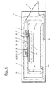
- Figures 1 and 3 show a fleece layer in the top view (1), which is designed as a so-called band layer. He has an upper main carriage in a housing or frame (54) (2) and a lower main carriage (3) and can over it one or more auxiliary wagons or tension wagons (32, 34) exhibit. Above the carriages (2,3,32,34) are means suitable rolls two endless laying tapes (5,6). At least the two main carriages (2, 3) are suitable Drives driven reciprocally. The two Laying tapes (5,6) can also be and variable speed drives.
- a pile generator e.g. one Card or a cardboard-produced fiber pile (7) arrives via a feed belt (25) into the fleece layer (1). He will via a feed path (26) to or on the upper main carriage (2) guided and arrives at the one described in more detail below Tape inlet (4.9) between the two laying tapes (5.6).
- the latter are at least in the area between the two Main carriage (2,3) in a loop parallel to each other and take the pile (7) between them, transport and guide him.
- This loop area is referred to as the outlet section (27). He can extend horizontally or diagonally and the main carriage (2,3) directly or via a fixed redirection (not shown) connect.
- the Outlet line (27) straight.
- the pile (7) emerges downwards and becomes on one transversely continuous take-off belt (8) to form a fleece (23) filed.
- the laying carriage (3) moves over the take-off belt (8) back and forth, causing the pile (8) in several layers one on top of the other across and zigzag to the delivery direction is filed.
- the pile (7) becomes scale-like paneled.
- the laying tapes (5,6) step on the laying carriage (3) again apart and are made in separate loops away from the outside and then to the tape inlet (9) again returned.
- the two main cars (2,3) can form a short Pass line in the same direction as in DE-A-19 27 863 or EP-A-0 517 568 or in opposite directions with stationary Belt deflection as with FR-A-2 553 102 or the WO 91/156018 move.
- To influence the pile placement on the trigger belt (8) can be by means of the auxiliary or Tensioners (32,34) internal storage are formed. It can also be worked with delay when laying the pile, around a certain thickness profile of the fleece (23) adjust.
- the tape inlet (4) movable and is located on the superstructure (2). He has one comparatively short inlet section (9) with a fixed one Length.
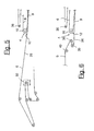
- Figures 3 to 6 show a variant with a stationary belt infeed (4) in front of the uppercarriage (2) is arranged. Here the inlet section (9) is larger and has a variable length.
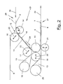
- FIG 2 illustrates the tape inlet (4) of the fleece layer (1) of Figure 1 in detail.
- the belt inlet (4) is located on the upper main carriage (2).
- the two meet behind the Laying trolley (3) again separately guided laying tapes (5,6) together, then run close together and take that from outside pile (7) between them.
- the embodiment shown serves a laying tape (5) at the same time as pile feeder (25) and is made accordingly the housing (54) of the fleece layer (1) led out.
- the Flor (7) lies open on the laying tape (5) and is transported from this to the tape inlet (4).
- the inlet slot (12) has an adjustable width that adapted to the respective requirements of the pile material can be. It is preferably somewhat larger than that Pile thickness, so that the loose pile (7) initially without Squeeze or compression can be included.
- the Width can also be equal to or less than the pile thickness and if necessary already when the pile (7) lead to a clamping in the tape inlet (4).
- the band sections (10,11) run essentially parallel. This can be strictly parallel. The distance of the Alternatively, it can also be determined by the running direction (24) reduce. This will make you look at an acute angle funnel-shaped tapering inlet section (9) formed in the pile (7) is gradually pressed together and clamped is before it reaches the lower deflection (15). At In this variant it can be advantageous to extend the width of the Inlet slot (12) larger than the pile thickness adjust. But it is also possible with a small one Slot width the pile (7) immediately upon entering the Tape inlet (4) to clamp and compression along the length to increase the inlet section (9) even further. The vote the appropriate setting depends on the type of Pile material and possibly also after Pile feed speed and / or other parameters.
- the inlet section (9) or the one forming it Band sections (10,11) are at an obtuse angle ⁇ against the horizontal or the feed or Inlet direction (24) inclined downwards.
- This obtuse angle ⁇ in Fig. 1 refers to the Belt deflection of the laying tape (5) on the deflection roller (14).
- the preferably horizontal feed path (26) of the Laying tape (5) is in the sloping tape section (10) redirected.
- the obtuse angle ⁇ between the band areas is greater than 90 ° and less than 180 °. He is preferably about 135 °.
- the pile (7) and the laying tapes (5,6) again preferably in one redirected horizontal direction and get over the Outlet section (27) to the laying carriage (3).
- the belt inlet (4) finds an overall deflection of the pile (5) or Laying tapes (5.6) instead of 180 °.
- the deflection at its upper end weaker and stronger at the lower end.
- the Belt inlet (4) is the pile (7) in front of the lower stronger one Redirection (15) over a longer straight section already safely guided and covered and does not get through it suddenly to the clamping point on the deflection (15).
- the laying tape (5) is preferably on the top over two Main carriage (2) deflection rollers arranged relatively stationary (14.15).
- the deflection rollers (14, 15) are corresponding to the slope of the inlet section (9) in the Height and laterally spaced.
- the upper deflection roller (16) of the other laying belt (6) is above the opposite deflecting roller (14) arranged.
- the line connecting the two roller axes runs approximately perpendicular to the incline of the inlet section (9).
- the laying tape has at the lower end of the inlet section (9) (6) two or more belt loops (13).
- the one Band loop (13) is located in front of the Deflection roller (15) formed deflection point and the second Band loop (13) behind it. Over the strap loops (13) becomes the one in the tape inlet (9) above or outside Laying tape (6) from the pile (7) at the critical deflection points replaced.
- the replacement will make them different Belt speeds in the area of the deflection avoided.
- the two laying tapes (5,6) move namely with the intervening pile around the axis of the Deflection roller (15).
- the laying tape on top (6) should due to its greater distance from this axis have a higher relative orbital velocity around which The pile (7) is tension-free over the entire deflection area to be able to lead.
- the two tapes (5,6) have the same orbital speed.
- the two Belt loops (13) eliminate the problem.
- the first belt loop (13) is made by deflecting rollers (17,18,19).
- the first deflecting roller (17) sits on lower end of the band section (11) and is above the deflection roller (15). It is arranged so that the connecting line between the two roller axes in approximately perpendicular to the inclination of the inlet slot (12) is aligned.
- the laying tape (6) or its overhead Band section (11) is approximately at one point detached from the pile (7) on which the one below Band section (10) on the deflecting roller (15). Of the The pile (7) arrives in the deflection area without distortion the roller (15).
- the laying tape (6) Via the deflection roller (19), which is offset obliquely to the rear the laying tape (6) is pulled out to the tape loop (13) and then returned to the guide roller (18).
- Latter is essentially at the same level as the Deflection roller (15) and has approximately the same diameter.
- the two laying tapes (5,6) come in approximately Axle height of the two rollers (15, 18) together again and can lead the pile (7) between them. You have with you essentially the same running speed that too is equal to the pile speed.
- the second belt loop is located behind the deflection roller (18) (13) by a laterally offset deflection roller (20) is pulled out.
- Their diameter is such that the laying tape (6) into a horizontal and deflected section parallel to the laying tape (5) becomes.
- this subsequent horizontal section the two tapes (5,6) so close together that they guide the pile (7) between them on both sides.
- a support device e.g. a support roller (21) for the laying tape (6) is arranged be.
- the support roller (21) affects the distance of the Laying tapes (5,6).
- the pile (7) in the Area of the lower deflection on the deflection roller (15) three places between the tapes (5,6) or clamped and therefore reliable and with the same Belt speeds led.
- the guide extends between the belt sections (10,11) just until the lower deflection roller is reached (15).
- the third management point is at the end of the redirection between the deflecting roller (15) and the preferably vertical support roller (21). At this The tape (5) leaves the guide roller again (15).
- the belt inlet (4) and the inlet section (9) are adjustable.
- the position of the delivery devices (22) can be changed.
- the infeed direction is preferably in the region of the inlet slot (12) located deflection rollers (16,17) essentially perpendicular to the direction of the Inlet section (9). This allows the width of the Inlet slot (12) and possibly also the funnel-shaped narrowing of the inlet section (9) changed become.
- the laying tapes (5, 6) can be permeable to air, so that due to the increasing narrowing of the inlet section (9) the pile pressed together with the air it contains is pushed out.
- the deflecting roller (18) is preferably horizontal adjustable and can be compared to the deflection roller (15) of the laying tape (5) can be approximated or removed. This will make the second leading point for the pile (7) influenced in the lower deflection area.
- the support roller (21) is vertically adjustable and can thereby also opposite the deflecting roller (15) be approximated or removed. With the backup roller (21) becomes the pile guide on said third Leadership influenced.
- the two begin the pile (7) receiving tape sections (10,11) approximately at the same height at the entrance of the inlet slot (12).
- the overhead band section (11) also pulled a little higher be and if necessary via the deflection point on the roller (14) protrude. This is e.g. to catch a very fast running pile cheap.
- the band section (11) but can also be arranged a little lower.
- the training, number and arrangement can also be changed the belt loops (13) at the lower end of the inlet section (9). For example, only one lower strap loop (13) to be available.
- the Inlet section (9) can also be somewhat curved.
- the fleece layer (1) has a separate embodiment Feed belt (25) over which the pile (7) of a arranged in front of it with a uniform but variable speed is supplied.
- the Fleece layer (1) is in turn equipped with four carriages, namely with an uppercarriage (2), a laying carriage (3) and one tensioning carriage (32,34) for each laying tape (5,6).
- the first laying tape (5) takes over in the area of Feed section (26) the pile (7) from the feed belt (25) and guides the pile (7) into a stationary one Tape inlet (4) between the two laying tapes (5,6), the up to the superstructure (2) and the deflection there (15) extends.
- the stationary belt inlet (4) is nearby the end of the path of movement of the superstructure (2) approximately in the middle of the laying width of the fleece layer (1).
- the laying tape (5) is the lower laying tape for the tape inlet (4) fed while the upper laying tape (6) over a Deflection roller (16) is fed.
- the stationary guide roller (16) has a Compared to the other deflecting rollers considerably larger Diameter on, whereby at the tape inlet (4) Inlet funnel is formed.
- the laying tapes (5,6) point at the belt inlet (4) e.g. a distance that is larger than the pile thickness.
- the inlet slot (12) thus formed enables the tape (7) to be fed in initially without substantial clamping or compression.
- Below the lower laying tape (5) is one in height adjustable support device (21) with which the gap width of the inlet slot (12) can be adjusted.
- the inlet slot (12) and the superstructure (2) extends the essentially straight inlet section (9), in which the tape sections (10,11) of the laying tapes (5,6) gradually converge so that they at the end of the inlet section (9) at the latest on the superstructure (2) have a distance that is adapted to the pile thickness.
- This distance can be, for example, the pile thickness correspond or to a fixed value, e.g. 15 mm, be set.
- the funnel-shaped narrowing Inlet section (9) gradually becomes the pile (7) guided and covered on both sides. This can done without compression. Alternatively, the pile (7) in the inlet section (9) also gradually compressed and be clamped.
- the inlet section (9) changes with the Movement of the superstructure (2) their length.
- the upper laying tape (6) as in above-described embodiment of a Guide roller (17) and on the rollers (18,19,20) below Formation of two ribbon loops (13) deflected several times, see above that the pile (7) in the deflection area on the superstructure (2) is not runs between the two laying tapes (5,6).
- the pile (7) is again between the two tapes (5,6).
- the one between the upper carriage (2) and the laying carriage (3) Outlet section (27) preferably runs in a straight line, the pile (7) after further deflection by 90 ° in the Laying carriage (3) exits at an exit point and from the floating laying carriage (3) on the Discharge belt (8) is deposited.
- the laying carriage (3) points also a guide roller (56) for the laying tape (5) after double deflection via the deflection rollers (60.62) again via further deflection rollers to the Tape inlet (4) is returned.
- the laying tape (6) will deflected via a deflection roller (58) and back to the Belt inlet (4) returned.
- the inlet section (9) and / or the outlet section (27) preferably run at an obtuse angle ⁇ to Horizontal in the direction of movement (24) of the laying tapes (5,6) diagonally downwards.
- This angle is as in the first Embodiment of Figures 1 and 2 between 90 ° and 180 ° and is e.g. approx. 170 °.
- a tension carriage (32) is provided for the laying tape (5), depending on the movement of the laying carriage (3) is controlled.
- a tension carriage is for the laying tape (6) (34) provided, depending on the movement of the Upper carriage (2) and the laying carriage (3) is controlled. The movement of the tensioning carriage (34) with the help of Toothed belt positively controlled.
- the tensioning carriage (34) is in the direction of rotation of the laying tape (6) behind a stationary deflection roller (36) and the further stationary deflection roller (16) at the belt inlet (4) arranged.
- Figure 4 shows the tape inlet (4) with an enlarged Scale, one from a perforated or screen roller existing pressure roller (30) the pile (7) before Pre-compress inlet slot (12).
- the pressure roller (30) can be at a predetermined distance from the lower one Laying tape (5) are held.
- FIG. 5 shows an alternative embodiment, at which the lower laying tape (5) in the inlet section (9) also serves as a feed belt (25).
- One before Leading section (9) in front of the belt inlet (4) Feed path (26) is in the same plane as that Inlet section (9) and is in relation to the horizontal Direction of movement of the laying tape (5) inclined downwards.
- Figure 6 shows a further embodiment in which the lower laying belt (5) also serves as a feed belt (25) serves.
- the laying tape (5) over the Deflection rollers (38 to 40) deflected several times, so that Laying tape (5) to form the inlet slot (12) Distance from the laying tape (6) of the inlet section (9) can be supplied.
- the deflection roller (39) can be adjusted in height be.
Landscapes
- Engineering & Computer Science (AREA)
- Textile Engineering (AREA)
- Preliminary Treatment Of Fibers (AREA)
- Nonwoven Fabrics (AREA)
- Cosmetics (AREA)
- Auxiliary Devices For And Details Of Packaging Control (AREA)
- Treatment Of Fiber Materials (AREA)
Description
Die Erfindung betrifft einen Vliesleger mit den Merkmalen im Oberbegriff der Verfahrens- und Vorrichtungshauptansprüche.The invention relates to a nonwoven layer with the features in the preamble of procedural and Device main claims.
Ein solcher Vliesleger ist aus der EP-0 609 907 A2 bekannt. Der als sogenannter Bandleger ausgebildete Vliesleger hat zwei relativ zueinander bewegliche Hauptwagen und zwei in Schleifen geführte endlose und umlaufend angetriebene Legebänder. Die Legebänder laufen zumindest im Abschnitt zwischen den Hauptwagen parallel, wobei sie den Flor zwischen sich aufnehmen und führen. Eingangsseitig hat der Vliesleger für die Floraufnahme einen sogenannten Bandeinlauf der Legebänder. Die von zwei Seiten herangeführten Legebänder treffen hier aufeinander und bilden eine Einlaufstrecke mit einem Öffnungswinkel der Legebänder von mindestens 20°. Der Einlaufschlitz am Eingang der Einlaufstrecke ist dadurch sehr groß und wesentlich weiter als die Flordicke. Der auf dem einen Legeband zugeführte Flor wird im Bandeinlauf mit einem stumpfen Winkel gegen die Horizontale schräg nach unten umgelenkt. Durch den großen Öffnungswinkel und den weiten Einlaufschlitz liegt der Flor in der Einlaufstrecke offen und wird erst am unteren Ende zwischen den zwei benachbarten Umlenkrollen zwischen den Legebändern geklemmt und beidseitig geführt. Der Flor kann sich in der Einlaufstrecke bei hohen Geschwindigkeiten vom unteren Legeband abheben. Dies kann vor allem bei empfindlichen Floren zu Störungen führen. Bei dieser Anordnung ist die Zuführgeschwindigkeit beschränkt.Such a fleece layer is known from EP-0 609 907 A2 known. The trained as a so-called band layer Fleece layer has two relatively movable Main carriage and two endless and looped all-round driven laying tapes. The tapes are running parallel at least in the section between the main carriages, taking up and guiding the pile between them. The fleece layer on the input side has a pile pick-up a so-called tape infeed of the laying tapes. That of two Side tapes come together here and form an inlet section with an opening angle of the tapes of at least 20 °. The inlet slot on The entrance to the inlet section is therefore very large and much wider than the pile thickness. The one Laying tape fed pile is in the tape infeed with a obtuse angles obliquely downwards against the horizontal redirected. Due to the large opening angle and the wide Inlet slit, the pile is open in the inlet section and is only at the bottom between the two adjacent pulleys between the laying tapes clamped and guided on both sides. The pile can be in the Inlet section at high speeds from the bottom Lift off the tape. This can be especially the case with sensitive Lead to faults. In this arrangement, the Feed speed limited.
Auch andere ähnliche Entwicklungen, z.B. gemäß der EP-A-0 517 568, tendieren dahin, vor dem Bandeinlauf einen sehr breiten und weit öffnenden Einlauftrichter zu schaffen. Hierbei hat das den Flor zuführende Legeband einen schräg abfallenden Bandabschnitt, auf dem Flor offen transportiert und erst am unteren Ende in einer Andrücklinie zwischen den zwei benachbarten Umlenkrollen und den Legebändern geklemmt und beidseitig geführt wird. Ein Unterschied zum vorgenannten Stand der Technik besteht nur in einer anderen Bandführung zwischen den Hauptwagen. Die Probleme am Bandeinlauf sind jedoch die gleichen wie bei der EP-0 609 907 A2.Other similar developments, e.g. according to the EP-A-0 517 568, tend to have one before the tape entry very wide and wide opening inlet funnel create. Here the laying tape feeds the pile a sloping band section, open on the pile transported and only in one at the lower end Pressure line between the two adjacent pulleys and the laying tapes are clamped and guided on both sides. There is a difference from the aforementioned prior art only in a different band guide between the main car. However, the problems with the tape entry are the same as at EP-0 609 907 A2.
Die FR-2 553 102 zeigt einen anderen Vliesleger. Im Bandeinlauf haben die beiden Legebänder zwei parallel nebeneinander laufende und gerade Bandabschnitte, die sich senkrecht nach unten erstrecken, wodurch der horizontal zugeführte Flor am Bandeinlauf eine Umlenkung um 90° erfährt. In der Praxis hat sich gezeigt, daß ein solcher Bandeinlauf ebenfalls nur für beschränkte Zuführgeschwindigkeiten des Flors und Arbeitsgeschwindigkeiten des Vlieslegers einsetzbar ist. Wenn die Zuführgeschwindigkeiten zu hoch werden, kann es zu Abrissen in dem sehr leichten und hochempfindlichen Faserflor kommen.FR-2 553 102 shows another nonwoven layer. in the Belt entry, the two laying tapes have two parallel juxtaposed and straight belt sections that are extend vertically downwards, making the horizontal fed pile at the belt inlet a deflection of 90 ° experiences. In practice it has been shown that such Belt infeed also only for limited Feed speeds of the pile and Working speeds of the fleece layer can be used. If the feed speeds get too high, it can to demolish in the very light and highly sensitive Fiber pile come.
Die WO 91/15618 zeigt eine weitere Variante des Bandeinlaufs, bei dem beide Legebänder am Hauptwagen über zwei große Umlenkwalzen geführt sind. Hierdurch bildet sich auch ein weiter Einlauftrichter für den auf dem einen Legeband zugeführten Flor. Die beiden großen Umlenkwalzen sind horizontal nebeneinander etwa auf gleicher Höhe angeordnet, wodurch der Flor nur etwa in Mittelpunktshöhe der beiden Walzen durch die hier nahe zusammentretenden Legebänder beidseits aufgenommen und geführt ist. Davor und danach treten die Legebänder durch die Walzenform wieder auseinander. Diese beiden vorgenannten Vliesleger sind zwar für höhere Zuführgeschwindigkeiten des Flors und Verarbeitungsgeschwindigkeiten des Vlieslegers konzipiert. Durch die nur punkt- bzw. linienweise Zusammenführung der Legebänder und die entsprechend kurze Führungslänge ergeben sich aber dennoch geschwindigkeitsbegrenzende Probleme.WO 91/15618 shows a further variant of the Belt infeed, in which both laying tapes over the main carriage two large deflection rollers are guided. This forms there is also another inlet funnel for one Placing tape fed pile. The two large deflection rollers are horizontally next to each other at about the same height arranged, whereby the pile only about at midpoint of the two rollers by the ones that come close together here Laying tapes are recorded and guided on both sides. Before and then the tapes pass through the roller shape apart again. These two aforementioned fleece layers are for higher feed speeds of the pile and Processing speeds of the fleece layer designed. By merging the Laying tapes and the correspondingly short guide length however, there are speed limits Problems.
Aus der DE-A 19 27 863 und der DE-A 24 29 106 sind ferner Vliesleger mit stationär angeordneten Bandeinläufen bekannt, bei denen die Legebänder über ortsfest angeordnete Umlenkwalzen geführt sind. Beide Vliesleger zeigen horizontale Bandeinläufe.From DE-A 19 27 863 and DE-A 24 29 106 are also Fleece layer with stationary belt inlets known, where the tapes over stationary arranged deflection rollers are guided. Both fleece layers show horizontal tape inlets.
Bei der DE-A 24 29 106 bilden die beiden Legebänder einen horizontalen Einlaufschlitz, der sich an das von der Krempel kommende Zuführband anschließt. Am oberen Hauptwagen werden die Legebänder voneinander gelöst, wobei der Flor um 90° nach unten umgelenkt und dabei nur auf dem einen untenliegenden Legeband transportiert und geführt wird. Bei der DE-A 19 27 863 wird der Flor über ein stationäres vorgeschaltetes Transportband zugeführt und vor dem Bandeinlauf im freien Fall auf einen darunterliegenden etwas schräg verlaufenden Legebandabschnitt gebracht. Das zweite Legeband ist erst mit einigem Abstand hinter dieser Stelle angeordnet. Der Einlaufschlitz entsteht dabei erst sehr spät an der Umlenkstelle in die folgende horizontale Einlaufstrecke des Bandeinlaufs. Beide Ausführungsformen mit dem stationären Bandeinlauf begrenzen in erheblichem Maße die Geschwindigkeiten von Florzuführung und Vliesleger. In DE-A 24 29 106 the two tapes form one horizontal inlet slot, which corresponds to that of the Carding incoming feed belt connects. At the top Main carts are loosened from each other, whereby the pile is deflected downwards by 90 ° and only on the transported and guided an underlying laying tape becomes. In DE-A 19 27 863 the pile is over stationary upstream conveyor belt fed and before the tape entry in free fall on one somewhat sloping underneath Laying tape section brought. The second laying tape is only some distance behind this point. Of the Inlet slot is created very late at the Deflection point in the following horizontal inlet section of the tape infeed. Both embodiments with the stationary belt infeed significantly limit the Speeds of pile feed and fleece layer.
Es ist Aufgabe der vorliegenden Erfindung, einen Vliesleger mit einem verbesserten Bandeinlauf aufzuzeigen.It is an object of the present invention to To show fleece layers with an improved tape infeed.
Die Erfindung löst diese Aufgabe mit den Merkmalen im
Hauptanspruch.
Beim erfindungsgemäßen Bandeinlauf ist wie beim Stand der
Technik eine schräg abwärts geneigte Einlaufstrecke
vorhanden, die im Gegensatz zum Stand der Technik aber von
zwei nahe beieinander laufenden Bandabschnitten gebildet
wird. Die Bandabschnitte bilden beim Eintritt in den
Bandeinlauf zwischen ihren benachbarten Umlenkwalzen einen
schmalen Einlaufschlitz, der an die Flordicke angepaßt
ist. In der anschließenden Einlaufstrecke nehmen die
beiden Bandabschnitte den zugeführten Flor auf und führen
ihn beidseitig und/oder decken ihn ab.The invention solves this problem with the features in the main claim.
In the tape inlet according to the invention, as in the prior art, there is an inclined downward sloping inlet section, which, in contrast to the prior art, is formed by two tape sections running close to one another. The belt sections form a narrow inlet slot between their adjacent deflecting rollers when they enter the belt inlet, which slot is adapted to the pile thickness. In the subsequent run-in section, the two belt sections take up the fed pile and guide it on both sides and / or cover it.
Die Bandabschnitte sind in einem stumpfen Winkel gegen die Zuführ- bzw. Einlaufrichtung schräg abwärts gerichtet. Dies hat wie beim Stand der Technik den Vorteil, daß die Florumlenkung sanfter erfolgt und die einwirkenden Fliehkräfte nicht zu groß werden. Dank der Schräglage kann der obenliegende Bandabschnitt als Abdeckung für den Flor an der Umlenkung wirken und ein Abheben des Flors durch Fliehkräfte, Windeffekte etc. verhindern.The band sections are at an obtuse angle against the Feed or infeed direction directed obliquely downwards. As in the prior art, this has the advantage that the Florum diversion takes place more gently and the acting Centrifugal forces do not get too big. Thanks to the inclined position the upper band section as a cover for the pile act on the deflection and lifting off the pile Prevent centrifugal forces, wind effects etc.
Der erfindungsgemäße Bandeinlauf sorgt für eine besonders schonende und sichere Aufnahme und Führung des Flors. Er erlaubt wesentlich höhere Bandlaufgeschwindigkeiten und Florzuführgeschwindigkeiten unter Wahrung einer hohen Funktions- und Betriebssicherheit.The tape inlet according to the invention ensures a special gentle and safe picking up and guiding of the pile. He allows much higher tape speeds and Pile feed speeds while maintaining a high Functional and operational security.
Die Bandabschnitte sind vorzugsweise gerade und können über eine gewisse Strecke im wesentlichen parallel laufen. Alternativ ist auch eine mit spitzem Winkel trichterförmig sich verengende Einlaufstrecke möglich. In der Einlaufstrecke kann der Flor wahlweise kopressionsfrei geführt oder allmählich zusammenpreßt bzw. geklemmt werden. Durch die trichterförmige Einlaufstrecke wird der schnellaufende Flor sicher gefaßt und die darin enthaltene Luft über einen längeren Weg- und Zeitabschnitt schonend herausgedrückt. Abrupte Klemmstellen, schnelle Luftströmungen und Turbulenzen, die den Flor schädigen oder zerstören könnten, werden vermieden. Dabei ist es vorteilhaft, wenn die Einlaufstrecke im wesentlichen gerade verläuft.The band sections are preferably straight and can run essentially parallel over a certain distance. Alternatively, one with a sharp angle is funnel-shaped narrowing inlet section possible. In the The pile can optionally be infeed-free guided or gradually pressed together or clamped become. Due to the funnel-shaped inlet section fast moving pile and the contained therein Air is gentle over a longer distance and time pushed out. Abrupt nips, quick Air currents and turbulence that damage the pile or could destroy them. It is advantageous if the inlet section essentially is going straight.
Durch die schräge Einlaufstrecke wird der Flor am oberen Ende sanft aufgenommen und erst am unteren Ende schärfer umgelenkt. Hierbei ist es vorteilhaft, an der unteren Umlenkstelle mindestens eine Bandschlaufe vorzusehen. In einer besonders vorteilhaften Ausgestaltung sind mindestens zwei Bandschlaufen vorhanden, wobei die erste Bandschlaufe vor der Umlenkstelle und die zweite Bandschlaufe dahinter angeordnet ist. Hierdurch werden an den kritischen Stellen der Umlenkung störende Relativgeschwindigkeiten der Legebänder bzw. deren Bandabschnitte verhindert. Der Flor kann dadurch besonders sicher und unbelastet umgelenkt werden. Der Flor wird dabei vorzugsweise an drei oder mehr Stellen im Umlenkbereich durch Umlenkwalzen geklemmt.The pile is at the top due to the sloping inlet section Gently absorbed at the end and sharper only at the lower end redirected. It is advantageous to use the lower one Deflection point to provide at least one belt loop. In a particularly advantageous embodiment There are at least two strap loops, the first Band loop in front of the deflection point and the second Band loop is arranged behind it. This will result in the critical points of the diversion Relative speeds of the laying tapes or their Band sections prevented. The pile can be special can be redirected safely and unencumbered. The pile will preferably at three or more points in the Deflection area clamped by deflection rollers.
Zur Anpassung an unterschiedliche Einsatzbedingungen des Vlieslegers, variierende Florarten etc. gibt es verschiedene Einstellmöglichkeiten am Bandeinlauf. Insbesondere kann die Weite und gegebenenfalls auch Neigung der Einlaufstrecke verändert werden. Die Verstellbarkeit des Abstandes der Legebänder ermöglicht eine exakte Anpassung an die Flordicke und die Einstellung der für den Transport des Flores notwendigen Reibungsbedingungen. Eine bevorzugte Einstellmöglichkeit liegt je nach Gestaltung des Bandeinlaufs in der Zustellung der verschiedenen Umlenkwalzen oder in einer plattenartigen Stützeinrichtung. Daneben sind aber auch noch andere konstruktive Varianten möglich.To adapt to different operating conditions of the There are fleece layers, varying pile types, etc. various setting options at the belt infeed. In particular, the width and possibly also Slope of the inlet section can be changed. The adjustability of the spacing of the tapes enables an exact adjustment to the pile thickness and the Setting the necessary for the transport of the pile Friction conditions. A preferred setting option depending on the design of the tape infeed Delivery of the different deflection rollers or in one plate-like support device. But there are also other design variants are possible.
Der Bandeinlauf kann stationär oder beweglich sein. In den bevorzugten Ausführungsbeispielen befindet er sich vor oder am oberen Hauptwagen.The tape infeed can be stationary or mobile. In the preferred embodiments it is located or on the upper main car.
Die zwischen dem Oberwagen und dem Legewagen verlaufende Auslaufstrecke kann ebenfalls unter einem Winkel zur Horizontalen verlaufen. Dies erlaubt eine weitere Verringerung des Umlenkwinkel des Flores im Oberwagen und eine Minderung der auf den Flor einwirkenden Fliehkräfte im Umlenkungsbereich.The one running between the uppercarriage and the laying carriage Outlet path can also be at an angle to Horizontal run. This allows one more Reduction of the deflection angle of the pile in the superstructure and a reduction in the centrifugal forces acting on the pile in the redirection area.
Das in der Einlaufstrecke untere Legeband kann in einer Vorlaufstrecke vor dem Einlauf geradlinig verlaufen. Der Flor wird von einem Zuführungsband auf dieses Legeband übertragen. Alternativ kann das in der Einlaufstrecke untere Legeband zugleich als Zuführungsband gestaltet sein. In diesem Fall kann das untere Legeband zur Bildung des Einlaufspaltes vor dem Einlauf zweifach umgelenkt sein. Die Gestaltung des unteren Legebandes zugleich als Zuführungsband spart einige Walzen und Antriebe ein und ist somit kostengünstiger.The lower laying tape in the inlet section can be in one Run straight ahead of the inlet. Of the The pile is fed from a feed belt onto this laying belt transfer. Alternatively, this can be done in the inlet section lower laying tape also designed as a feed belt be. In this case, the lower tape can be used for formation of the inlet gap before the inlet is redirected twice be. The design of the lower tape as well Feed belt saves some rollers and drives and is therefore cheaper.
Vor dem Bandeinlauf kann eine Andrückwalze, vorzugsweise eine Sieb- oder Lochwalze auf dem Flor aufliegen, die dazu dient, Luft aus dem Flor zu entfernen.Before the tape entry, a pressure roller, preferably a sieve or perforated roller lie on the pile to do this serves to remove air from the pile.
Bei einem alternativen Ausführungsbeispiel kann die Zuführstrecke und die Einlaufstrecke in einer gemeinsamen Ebene liegen. Diese Ebene ist relativ zur Horizontalen um einen Winkel nach unten zum Oberwagen hin geneigt. Bei einer derartigen Einlaufzone, wird der Flor nicht unnötig umgelenkt und kann geradlinig dem Oberwagen zugeführt werden.In an alternative embodiment, the Feed line and the inlet line in a common Level. This plane is around relative to the horizontal inclined downwards towards the superstructure. At In such an entry zone, the pile is not unnecessary deflected and can be fed straight to the superstructure become.
In den Unteransprüchen sind weitere vorteilhafte Ausgestaltungen der Erfindung angegeben. In the subclaims are further advantageous Embodiments of the invention specified.
Die Erfindung ist in den Zeichnungen beispielsweise und schematisch dargestellt. Im einzelnen zeigen:
- Figur 1:
- eine Übersichtsdarstellung eines Vlieslegers mit einem bewegten Bandeinlauf am Legewagen,
- Figur 2:
- eine vergrößerte und detaillierte Detailansicht des Bandeinlaufs von Fig. 1,
- Figur 3:
- eine Übersichtsdarstellung eines Vlieslegers in Variation zu Fig. 1 mit einem stationären Bandeinlauf,
- Figur 4:
- eine Detaildarstellung des Bandeinlaufs von Fig. 3 mit einer vorgelagerten Andrückwalze,
- Figur 5:
- ein alternatives Ausführungsbeispiel des Bandeinlaufs von Fig. 4, bei dem das untere Legeband zugleich das Zuführungsband ist, und
- Figur 6:
- ein weiteres alternatives Ausführungsbeispiel zu
Fig. 4
und 5, bei dem das untere Legeband zugleich das Zuführungsband ist.
- Figure 1:
- an overview of a fleece layer with a moving belt infeed on the laying carriage,
- Figure 2:
- 2 shows an enlarged and detailed detailed view of the tape inlet of FIG. 1,
- Figure 3:
- 1 shows an overview of a nonwoven layer in variation to FIG. 1 with a stationary belt inlet,
- Figure 4:
- 3 shows a detailed illustration of the strip inlet of FIG. 3 with an upstream pressure roller,
- Figure 5:
- an alternative embodiment of the tape inlet of Fig. 4, in which the lower laying tape is also the feed belt, and
- Figure 6:
- a further alternative embodiment to FIGS. 4 and 5, in which the lower laying belt is also the feed belt.
Figur 1 und 3 zeigen in der Obersicht einen Vliesleger (1), der als sogenannter Bandleger ausgebildet ist. Er hat in einem Gehäuse oder Gestell (54) einen oberen Hauptwagen (2) und einen unteren Hauptwagen (3) und kann darüber hinaus ein oder mehrere Hilfswagen oder Spannwagen (32,34) aufweisen. Ober die Wagen (2,3,32,34) sind mittels geeigneter Rollen zwei endlose Legebänder (5,6) geführt. Zumindest die beiden Hauptwagen (2,3) sind durch geeignete Antriebe hin- und herbeweglich angetrieben. Die beiden Legebänder (5,6) sind ebenfalls mittels geeigneter steuer- und regelbarer Antriebe umlaufend angetrieben. Figures 1 and 3 show a fleece layer in the top view (1), which is designed as a so-called band layer. He has an upper main carriage in a housing or frame (54) (2) and a lower main carriage (3) and can over it one or more auxiliary wagons or tension wagons (32, 34) exhibit. Above the carriages (2,3,32,34) are means suitable rolls two endless laying tapes (5,6). At least the two main carriages (2, 3) are suitable Drives driven reciprocally. The two Laying tapes (5,6) can also be and variable speed drives.
Der von einem Florerzeuger (nicht dargestellt), z.B. einer Karde oder einer Krempel erzeugte Faserflor (7) gelangt über ein Zuführband (25) in den Vliesleger (1). Er wird über eine Zuführstrecke (26) zum oder am oberen Hauptwagen (2) geführt und gelangt am nachfolgend näher beschriebenen Bandeinlauf (4,9) zwischen die beiden Legebänder (5,6). Letztere sind die zumindest im Bereich zwischen den beiden Hauptwagen (2,3) in einer Schleife parallel zueinander geführt und nehmen den Flor (7) zwischen sich auf, transportieren und führen ihn. Dieser Schleifenbereich wird als Auslaufstrecke (27) bezeichnet. Er kann sich horizontal oder schräg erstrecken und die Hauptwagen (2,3) direkt oder über eine gestellfeste Umlenkung (nicht dargestellt) verbinden. Vorzugsweise verläuft die Auslaufstrecke (27) geradlinig.That from a pile generator (not shown), e.g. one Card or a cardboard-produced fiber pile (7) arrives via a feed belt (25) into the fleece layer (1). He will via a feed path (26) to or on the upper main carriage (2) guided and arrives at the one described in more detail below Tape inlet (4.9) between the two laying tapes (5.6). The latter are at least in the area between the two Main carriage (2,3) in a loop parallel to each other and take the pile (7) between them, transport and guide him. This loop area is referred to as the outlet section (27). He can extend horizontally or diagonally and the main carriage (2,3) directly or via a fixed redirection (not shown) connect. Preferably, the Outlet line (27) straight.
Am unteren Hauptwagen (3), dem sogenannten Legewagen, tritt der Flor (7) nach unten aus und wird auf einem querlaufenden endlosen Abzugsband (8) zu einem Vlies (23) abgelegt. Der Legewagen (3) fährt über dem Abzugsband (8) hin und her, wodurch der Flor (8) in mehreren Lagen übereinander quer und im Zickzack zur Anlieferungsrichtung abgelegt wird. Der Flor (7) wird dabei schuppenartig aufgetäfelt. Die Legebänder (5,6) treten am Legewagen (3) wieder auseinander und werden in separaten Schleifen nach außen weg und dann zum Bandeinlauf (9) wieder zurückgeführt.On the lower main carriage (3), the so-called laying carriage, the pile (7) emerges downwards and becomes on one transversely continuous take-off belt (8) to form a fleece (23) filed. The laying carriage (3) moves over the take-off belt (8) back and forth, causing the pile (8) in several layers one on top of the other across and zigzag to the delivery direction is filed. The pile (7) becomes scale-like paneled. The laying tapes (5,6) step on the laying carriage (3) again apart and are made in separate loops away from the outside and then to the tape inlet (9) again returned.
Für die konstruktive Ausbildung und Funktion des Vlieslegers (1) gibt es verschiedenste Möglichkeiten, wie sie z.B. aus dem in der Beschreibungseinleitung genannten Stand der Technik bekannt sind. Die beiden Hauptwagen (2,3) können sich dabei zur Bildung einer kurzen Durchlaufstrecke gleichsinnig wie bei der DE-A-19 27 863 bzw. der EP-A-0 517 568 oder gegensinnig mit stationärer Bandumlenkung wie bei der FR-A-2 553 102 oder der WO 91/156018 bewegen. Zur Beeinflussung der Florablage auf dem Abzugsband (8) können mittels der Hilfs- oder Spannwagen (32,34) interne Speicher gebildet werden. Es kann bei der Florablage auch mit Verzug gearbeitet werden, um ein bestimmtes Dickenprofil des Vlieses (23) einzustellen.For the constructive training and function of the Fleece layer (1) there are various ways, such as they e.g. from that mentioned in the introduction to the description State of the art are known. The two main cars (2,3) can form a short Pass line in the same direction as in DE-A-19 27 863 or EP-A-0 517 568 or in opposite directions with stationary Belt deflection as with FR-A-2 553 102 or the WO 91/156018 move. To influence the pile placement on the trigger belt (8) can be by means of the auxiliary or Tensioners (32,34) internal storage are formed. It can also be worked with delay when laying the pile, around a certain thickness profile of the fleece (23) adjust.
Beim Vliesleger von Figur 1 und 2 ist der Bandeinlauf (4) beweglich und befindet sich am Oberwagen (2). Er hat eine vergleichsweise kurze Einlaufstrecke (9) mit einer festen Länge. Die Figuren 3 bis 6 zeigen eine Variante mit einem stationären Bandeinlauf (4), der vor dem Oberwagen (2) angeordnet ist. Hier ist die Einlaufstrecke (9) größer und hat eine veränderliche Länge.In the nonwoven layer of Figures 1 and 2, the tape inlet (4) movable and is located on the superstructure (2). He has one comparatively short inlet section (9) with a fixed one Length. Figures 3 to 6 show a variant with a stationary belt infeed (4) in front of the uppercarriage (2) is arranged. Here the inlet section (9) is larger and has a variable length.
Figur 2 verdeutlicht den Bandeinlauf (4) des Vlieslegers (1) von Figur 1 im Detail. Bei dieser Ausführungsform befindet sich der Bandeinlauf (4) am oberen Hauptwagen (2). Am Bandeinlauf (4) treffen die beiden hinter dem Legewagen (3) wieder getrennt geführten Legebänder (5,6) zusammen, laufen dann nahe beieinander und nehmen den von außen zugeführten Flor (7) zwischen sich auf. In der gezeigten Ausführungsform dient das eine Legeband (5) zugleich als Florzuführung (25) und ist entsprechend aus dem Gehäuse (54) des Vlieslegers (1) herausgeführt. Der Flor (7) liegt hier offen auf dem Legeband (5) und wird von diesem zum Bandeinlauf (4) transportiert.Figure 2 illustrates the tape inlet (4) of the fleece layer (1) of Figure 1 in detail. In this embodiment the belt inlet (4) is located on the upper main carriage (2). At the tape inlet (4) the two meet behind the Laying trolley (3) again separately guided laying tapes (5,6) together, then run close together and take that from outside pile (7) between them. In the the embodiment shown serves a laying tape (5) at the same time as pile feeder (25) and is made accordingly the housing (54) of the fleece layer (1) led out. Of the Flor (7) lies open on the laying tape (5) and is transported from this to the tape inlet (4).
Am Bandeinlauf (4) werden die beiden Legebänder (5,6) unter Bildung eines schmalen Einlaufschlitzes (12) über Umlenkwalzen (14,16) zusammengeführt. An die Umlenkwalzen (14,16) schließt sich die Einlaufstrecke (9) an, die von zwei im wesentlichen sich gerade erstreckenden Bandabschnitten (10,11) der Legebänder (5,6) bis zu einer weiteren Umlenkung (15) gebildet wird. Die Bandabschnitte (10,11) nehmen den Flor (7) zwischen sich auf und decken ihn ab bzw. führen ihn beidseitig entlang der Einlaufstrecke (9).At the tape infeed (4) the two laying tapes (5,6) forming a narrow inlet slot (12) Deflection rollers (14, 16) brought together. To the deflection rollers (14,16) is followed by the inlet section (9) by two essentially straight ones Band sections (10,11) of the laying tapes (5,6) up to one further deflection (15) is formed. The band sections (10,11) take the pile (7) between them and cover remove it or guide it along both sides of the Inlet section (9).
Der Einlaufschlitz (12) hat eine einstellbare Weite, die an die jeweiligen Erfordernisse des Flormaterials angepaßt werden kann. Vorzugsweise ist sie etwas größer als die Flordicke, so daß der lockere Flor (7) zunächst ohne Zwängung oder Kompression aufgenommen werden kann. Die Weite kann aber auch gleich oder kleiner als die Flordicke sein und gegebenenfalls bereits bei Eintritt des Flors (7) in den Bandeinlauf (4) zu einer Klemmung führen.The inlet slot (12) has an adjustable width that adapted to the respective requirements of the pile material can be. It is preferably somewhat larger than that Pile thickness, so that the loose pile (7) initially without Squeeze or compression can be included. The Width can also be equal to or less than the pile thickness and if necessary already when the pile (7) lead to a clamping in the tape inlet (4).
Die Bandabschnitte (10,11) laufen im wesentlichen parallel. Dies kann streng parallel sein. Der Abstand der kann sich alternativ aber auch über die Laufrichtung (24) verringern. Dadurch wird eine sich im spitzen Winkel trichterförmig verjüngende Einlaufstrecke (9) gebildet, in der der Flor (7) allmählich zusammengepreßt und geklemmt wird, bevor er die untere Umlenkung (15) erreicht. Bei dieser Variante kann es günstig sein, die Weite des Einlaufschlitzes (12) größer als die Flordicke einzustellen. Es ist aber auch möglich, bei einer kleinen Schlitzweite den Flor (7) gleich beim Eintritt in den Bandeinlauf (4) zu klemmen und die Kompression über die Länge der Einlaufstrecke (9) noch weiter zu erhöhen. Die Wahl der geeigneten Einstellung richtet sich nach der Art des Flormaterials und gegebenenfalls auch nach der Florzuführgeschwindigkeit und/oder anderen Parametern.The band sections (10,11) run essentially parallel. This can be strictly parallel. The distance of the Alternatively, it can also be determined by the running direction (24) reduce. This will make you look at an acute angle funnel-shaped tapering inlet section (9) formed in the pile (7) is gradually pressed together and clamped is before it reaches the lower deflection (15). At In this variant it can be advantageous to extend the width of the Inlet slot (12) larger than the pile thickness adjust. But it is also possible with a small one Slot width the pile (7) immediately upon entering the Tape inlet (4) to clamp and compression along the length to increase the inlet section (9) even further. The vote the appropriate setting depends on the type of Pile material and possibly also after Pile feed speed and / or other parameters.
Die Einlaufstrecke (9) bzw. die sie bildenden Bandabschnitte (10,11) sind in einem stumpfen Winkel β gegen die Horizontale oder die Zuführ- bzw. Einlaufrichtung (24) schräg abwärts geneigt. Dieser stumpfe Winkel β bezieht sich in Fig. 1 auf die Bandumlenkung des Legebands (5) an der Umlenkwalze (14). Die vorzugsweise horizontale Zuführstrecke (26) des Legebandes (5) wird in den schrägen Bandabschnitt (10) umgelenkt. Der stumpfe Winkel β zwischen den Bandbereichen ist größer als 90° und kleiner als 180°. Er beträgt vorzugsweise ca. 135°.The inlet section (9) or the one forming it Band sections (10,11) are at an obtuse angle β against the horizontal or the feed or Inlet direction (24) inclined downwards. This obtuse angle β in Fig. 1 refers to the Belt deflection of the laying tape (5) on the deflection roller (14). The preferably horizontal feed path (26) of the Laying tape (5) is in the sloping tape section (10) redirected. The obtuse angle β between the band areas is greater than 90 ° and less than 180 °. He is preferably about 135 °.
Am unteren Ende der Einlaufstrecke (9) werden der Flor (7) und die Legebänder (5,6) wieder in eine vorzugsweise horizontale Richtung umgelenkt und gelangen über die Auslaufstrecke (27) zum Legewagen (3). Am Bandeinlauf (4) findet damit eine Gesamtumlenkung des Flors (5) bzw. der Legebänder (5,6) um 180° statt. Durch die Schräge der Einlaufstrecke (9) ist die Umlenkung an deren oberem Ende schwächer und am unteren Ende stärker. Durch den Bandeinlauf (4) ist der Flor (7) vor der unteren stärkeren Umlenkung (15) über eine längere gerade Strecke bereits sicher geführt und abgedeckt und gelangt dadurch nicht plötzlich an die Klemmstelle an der Umlenkung (15).At the lower end of the inlet section (9) the pile (7) and the laying tapes (5,6) again preferably in one redirected horizontal direction and get over the Outlet section (27) to the laying carriage (3). At the belt inlet (4) thus finds an overall deflection of the pile (5) or Laying tapes (5.6) instead of 180 °. Through the slope of the Inlet section (9) is the deflection at its upper end weaker and stronger at the lower end. By the Belt inlet (4) is the pile (7) in front of the lower stronger one Redirection (15) over a longer straight section already safely guided and covered and does not get through it suddenly to the clamping point on the deflection (15).
Das Legeband (5) ist über zwei vorzugsweise am oberen Hauptwagen (2) relativ ortsfest angeordnete Umlenkwalzen (14,15) geführt. Die Umlenkwalzen (14,15) sind entsprechend der Schräge der Einlaufstrecke (9) in der Höhe und seitlich distanziert.The laying tape (5) is preferably on the top over two Main carriage (2) deflection rollers arranged relatively stationary (14.15). The deflection rollers (14, 15) are corresponding to the slope of the inlet section (9) in the Height and laterally spaced.
Die obere Umlenkwalze (16) des anderen Legebandes (6) ist oberhalb der gegenüberliegenden Umlenkwalze (14) angeordnet. Die Verbindungslinie der beiden Walzenachsen verläuft in etwa senkrecht zur Neigung der Einlaufstrecke (9).The upper deflection roller (16) of the other laying belt (6) is above the opposite deflecting roller (14) arranged. The line connecting the two roller axes runs approximately perpendicular to the incline of the inlet section (9).
Am unteren Ende der Einlaufstrecke (9) hat das Legeband (6) zwei oder mehr Bandschlaufen (13). Die eine Bandschlaufe (13) befindet sich vor der durch die Umlenkwalze (15) gebildeten Umlenkstelle und die zweite Bandschlaufe (13) dahinter. Über die Bandschlaufen (13) wird das im Bandeinlauf (9) oben bzw. außen liegende Legeband (6) vom Flor (7) an den kritischen Umlenkpunkten abgelöst. The laying tape has at the lower end of the inlet section (9) (6) two or more belt loops (13). The one Band loop (13) is located in front of the Deflection roller (15) formed deflection point and the second Band loop (13) behind it. Over the strap loops (13) becomes the one in the tape inlet (9) above or outside Laying tape (6) from the pile (7) at the critical deflection points replaced.
Durch die Ablösung werden unterschiedliche Bandlaufgeschwindigkeiten im Bereich der Umlenkung vermieden. Die beiden Legebänder (5,6) bewegen sich nämlich mit dem dazwischenliegenden Flor um die Achse der Umlenkwalze (15). Das obenliegende Legeband (6) müßte durch seinen größeren Abstand von dieser Achse eigentlicn eine höhere relative Umlaufgeschwindigkeit haben, um den Flor (7) über den gesamten Umlenkbereich spannungsfrei führen zu können. Die beiden Legebänder (5,6) haben jedoch die gleiche Umlaufgeschwindigkeit. Die beiden Bandschlaufen (13) beseitigen das Problem.The replacement will make them different Belt speeds in the area of the deflection avoided. The two laying tapes (5,6) move namely with the intervening pile around the axis of the Deflection roller (15). The laying tape on top (6) should due to its greater distance from this axis have a higher relative orbital velocity around which The pile (7) is tension-free over the entire deflection area to be able to lead. However, the two tapes (5,6) have the same orbital speed. The two Belt loops (13) eliminate the problem.
Die erste Bandschlaufe (13) wird durch Umlenkwalzen (17,18,19) gebildet. Die erste Umlenkwalze (17) sitzt am unteren Ende des Bandabschnitts (11) und befindet sich oberhalb der Umlenkwalze (15). Sie ist so angeordnet, daß die Verbindungslinie zwischen den beiden Walzenachsen in etwa senkrecht zur Neigung des Einlaufschlitzes (12) ausgerichtet ist. Das Legeband (6) bzw. sein obenliegender Bandabschnitt (11) wird dadurch in etwa an einer Stelle vom Flor (7) abgelöst, an der der untenliegende Bandabschnitt (10) auf die Umlenkwalze (15) gerät. Der Flor (7) kommt dadurch verzugsfrei in den Umlenkbereich an der Walze (15).The first belt loop (13) is made by deflecting rollers (17,18,19). The first deflecting roller (17) sits on lower end of the band section (11) and is above the deflection roller (15). It is arranged so that the connecting line between the two roller axes in approximately perpendicular to the inclination of the inlet slot (12) is aligned. The laying tape (6) or its overhead Band section (11) is approximately at one point detached from the pile (7) on which the one below Band section (10) on the deflecting roller (15). Of the The pile (7) arrives in the deflection area without distortion the roller (15).
Über die schräg nach hinten versetzte Umlenkwalze (19) wird das Legeband (6) zur Bandschlaufe (13) ausgezogen und dann wieder zur Umlenkwalze (18) zurückgeführt. Letztere befindet sich im wesentlichen auf gleicher Höhe mit der Umlenkwalze (15) und hat in etwa den gleichen Durchmesser. Dadurch kommen die beiden Legebänder (5,6) etwa in Achshöhe der beiden Walzen (15,18) wieder zusammen und können den Flor (7) zwischen sich führen. Sie haben dabei im wesentlichen die gleiche Laufgeschwindigkeit, die auch gleich der Florgeschwindigkeit ist. Via the deflection roller (19), which is offset obliquely to the rear the laying tape (6) is pulled out to the tape loop (13) and then returned to the guide roller (18). Latter is essentially at the same level as the Deflection roller (15) and has approximately the same diameter. As a result, the two laying tapes (5,6) come in approximately Axle height of the two rollers (15, 18) together again and can lead the pile (7) between them. You have with you essentially the same running speed that too is equal to the pile speed.
Hinter der Umlenkwalze (18) sitzt die zweite Bandschlaufe (13), die durch eine seitlich versetzte Umlenkwalze (20) ausgezogen wird. Deren Durchmesser ist so bemessen, daß das Legeband (6) anschließend in einen horizontalen und parallel zum Legeband (5) verlaufenden Abschnitt umgelenkt wird. In diesem anschließenden Horizontalabschnitt liegen die beiden Legebänder (5,6) wieder so eng beieinander, daß sie den Flor (7) zwischen sich beidseits führen.The second belt loop is located behind the deflection roller (18) (13) by a laterally offset deflection roller (20) is pulled out. Their diameter is such that the laying tape (6) into a horizontal and deflected section parallel to the laying tape (5) becomes. In this subsequent horizontal section the two tapes (5,6) so close together that they guide the pile (7) between them on both sides.
Unterhalb der Umlenkwalze (15) kann eine Stützeinrichtung, z.B. eine Stützwalze (21) für das Legeband (6) angeordnet sein. Die Stützwalze (21) beeinflußt den Abstand der Legebänder (5,6).Below the deflection roller (15), a support device, e.g. a support roller (21) for the laying tape (6) is arranged be. The support roller (21) affects the distance of the Laying tapes (5,6).
Durch die gezeigte Walzenanordnung wird der Flor (7) im Bereich der unteren Umlenkung an der Umlenkwalze (15) an drei Stellen zwischen den Legebändern (5,6) geklemmt oder eingespannt und dadurch zuverlässig und mit gleichen Bandgeschwindigkeiten geführt. Am Ende der Einlaufstrecke (9) reicht die Führung zwischen den Bandabschnitten (10,11) gerade bis zum Erreichen der unteren Umlenkwalze (15). Danach findet wieder eine beidseitige Führung etwa in Höhe der Achsen der Umlenkwalzen (15,18) statt. Die dritte Führungsstelle befindet sich am Ende der Umlenkung zwischen der Umlenkwalze (15) und der vorzugsweise senkrecht darunterliegenden Stützwalze (21). An dieser Stelle verläßt das Legeband (5) wieder die Umlenkwalze (15).Due to the roller arrangement shown, the pile (7) in the Area of the lower deflection on the deflection roller (15) three places between the tapes (5,6) or clamped and therefore reliable and with the same Belt speeds led. At the end of the inlet section (9) the guide extends between the belt sections (10,11) just until the lower deflection roller is reached (15). Then there is a two-sided tour again at the level of the axes of the deflecting rollers (15, 18). The third management point is at the end of the redirection between the deflecting roller (15) and the preferably vertical support roller (21). At this The tape (5) leaves the guide roller again (15).
Der Bandeinlauf (4) bzw. die Einlaufstrecke (9) sind verstellbar. Beispielsweise können die Umlenkwalzen (16,17,18) und die Stützwalze (21) mit geeigneten Zustelleinrichtungen (22) in ihrer Lage verändert werden. Vorzugsweise ist die Zustellrichtung bei den im Bereich des Einlaufschlitzes (12) befindlichen Umlenkwalzen (16,17) im wesentlichen senkrecht zur Richtung der Einlaufstrecke (9). Dadurch kann die Weite des Einlaufschlitzes (12) und gegebenenfalls auch die trichterförmige Verengung der Einlaufstrecke (9) verändert werden. Die Legebänder (5,6) können luftdurchlässig sein, so daß durch die zunehmende Verengung der Einlaufstrecke (9) der Flor zusammengepreßt und dabei die enthaltene Luft herausgedrückt wird.The belt inlet (4) and the inlet section (9) are adjustable. For example, the deflection rollers (16,17,18) and the backup roller (21) with suitable The position of the delivery devices (22) can be changed. The infeed direction is preferably in the region of the inlet slot (12) located deflection rollers (16,17) essentially perpendicular to the direction of the Inlet section (9). This allows the width of the Inlet slot (12) and possibly also the funnel-shaped narrowing of the inlet section (9) changed become. The laying tapes (5, 6) can be permeable to air, so that due to the increasing narrowing of the inlet section (9) the pile pressed together with the air it contains is pushed out.
Die Umlenkwalze (18) ist vorzugsweise horizontal verstellbar und kann dadurch gegenüber der Umlenkwalze (15) des Legebandes (5) angenähert oder entfernt werden. Hierdurch wird die zweite Führungsstelle für den Flor (7) im unteren Umlenkbereich beeinflußt.The deflecting roller (18) is preferably horizontal adjustable and can be compared to the deflection roller (15) of the laying tape (5) can be approximated or removed. This will make the second leading point for the pile (7) influenced in the lower deflection area.
Die Stützwalze (21) ist vertikal verstellbar und kann dadurch ebenfalls gegenüber der Umlenkwalze (15) angenähert bzw. entfernt werden. Mit der Stützwalze (21) wird die Florführung an der besagten dritten Führungsstelle beeinflußt.The support roller (21) is vertically adjustable and can thereby also opposite the deflecting roller (15) be approximated or removed. With the backup roller (21) becomes the pile guide on said third Leadership influenced.
Die Laufrichtung des Flors (7) bzw. des ihn zuführenden Legebandes (5) im Bereich des Bandeinlaufs (9) ist durch Pfeile (24) markiert.The running direction of the pile (7) or the one feeding it Laying tape (5) in the area of the tape inlet (9) is through Arrows (24) marked.
Abwandlungen der gezeigten Ausführungsform sind in verschiedener Weise möglich. Im gezeigten Ausführungsbeispiel beginnen die beiden den Flor (7) aufnehmenden Bandabschnitte (10,11) etwa in gleicher Höhe am Eingang des Einlaufschlitzes (12). Alternativ kann der obenliegende Bandabschnitt (11) auch etwas höher gezogen sein und gegebenenfalls über die Umlenkstelle an der Walze (14) hinausragen. Dies ist z.B. zum Fangen eines sehr schnell laufenden Flor günstig. Der Bandabschnitt (11) kann aber auch noch etwas tiefer angeordnet sein. Veränderbar ist ferner die Ausbildung, Zahl und Anordnung der Bandschlaufen (13) am unteren Ende der Einlaufstrecke (9). Es kann z.B. nur die eine untere Bandschlaufe (13) vorhanden sein. Variabel sind auch die Einstell- und Zustellmöglichkeiten der einzelnen Umlenkwalzen oder sonstiger bandführender Teile am Bandeinlauf (4). Die Einlaufstrecke (9) kann auch etwas gekrümmt verlaufen.Variations of the embodiment shown are in FIG possible in different ways. In the shown Embodiment, the two begin the pile (7) receiving tape sections (10,11) approximately at the same height at the entrance of the inlet slot (12). Alternatively, the overhead band section (11) also pulled a little higher be and if necessary via the deflection point on the roller (14) protrude. This is e.g. to catch a very fast running pile cheap. The band section (11) but can also be arranged a little lower. The training, number and arrangement can also be changed the belt loops (13) at the lower end of the inlet section (9). For example, only one lower strap loop (13) to be available. The setting and Delivery options for the individual guide rollers or other belt-guiding parts at the belt inlet (4). The Inlet section (9) can also be somewhat curved.
Bei dem in Figur 3 gezeigten alternativen Ausführungsbeispiel weist der Vliesleger (1) ein separates Zuführungsband (25) auf, über das der Flor (7) von einer davor angeordneten Krempel mit einer gleichmäßigen aber veränderbaren Geschwindigkeit zugeführt wird. Der Vliesleger (1) ist wiederum mit vier Wagen ausgerüstet, nämlich mit einem Oberwagen (2), einem Legewagen (3) und jeweils einem Spannwagen (32,34) für jedes Legeband (5,6).In the alternative shown in Figure 3 The fleece layer (1) has a separate embodiment Feed belt (25) over which the pile (7) of a arranged in front of it with a uniform but variable speed is supplied. Of the Fleece layer (1) is in turn equipped with four carriages, namely with an uppercarriage (2), a laying carriage (3) and one tensioning carriage (32,34) for each laying tape (5,6).
Das erste Legeband (5) übernimmt im Bereich der Zuführstrecke (26) den Flor (7) von dem Zuführungsband (25) und führt den Flor (7) in einen ortsfesten Bandeinlauf (4) zwischen den beiden Legebändern (5,6), der sich bis zum Oberwagen (2) und der dortigen Umlenkung (15) erstreckt. Der ortsfeste Bandeinlauf (4) ist in der Nähe des Endes des Bewegungsweges des Oberwagens (2) etwa in der Mitte der Legebreite des Vlieslegers (1) angeordnet. Das Legeband (5) wird als unteres Legeband dem Bandeinlauf (4) zugeführt, während das obere Legeband (6) über eine Umlenkwalze (16) zugeführt wird.The first laying tape (5) takes over in the area of Feed section (26) the pile (7) from the feed belt (25) and guides the pile (7) into a stationary one Tape inlet (4) between the two laying tapes (5,6), the up to the superstructure (2) and the deflection there (15) extends. The stationary belt inlet (4) is nearby the end of the path of movement of the superstructure (2) approximately in the middle of the laying width of the fleece layer (1). The laying tape (5) is the lower laying tape for the tape inlet (4) fed while the upper laying tape (6) over a Deflection roller (16) is fed.
Die ortsfest gelagerte Umlenkwalze (16) weist einen im Vergleich zu den anderen Umlenkwalzen erheblich größeren Durchmesser auf, wodurch am Bandeinlauf (4) ein Einlauftrichter gebildet ist. Die Legebänder (5,6) weisen am Bandeinlauf (4) z.B. einen Abstand auf, der größer ist als die Flordicke. Der so gebildete Einlaufschlitz (12) ermöglicht den Bandeinlauf des Flores (7) anfänglich ohne wesentliche Klemmung oder Kompression. Unterhalb des unteren Legebandes (5) befindet sich eine in der Höhe einstellbare Stützeinrichtung (21), mit der die Spaltweite des Einlaufschlitzes (12) eingestellt werden kann. The stationary guide roller (16) has a Compared to the other deflecting rollers considerably larger Diameter on, whereby at the tape inlet (4) Inlet funnel is formed. The laying tapes (5,6) point at the belt inlet (4) e.g. a distance that is larger than the pile thickness. The inlet slot (12) thus formed enables the tape (7) to be fed in initially without substantial clamping or compression. Below the lower laying tape (5) is one in height adjustable support device (21) with which the gap width of the inlet slot (12) can be adjusted.
Zwischen dem Einlaufschlitz (12) und dem Oberwagen (2) erstreckt sich die im wesentlichen gerade Einlaufstrecke (9), in der die Bandabschnitte (10,11) der Legebänder (5,6) allmählich aufeinander zulaufen, so daß sie spätestens am Ende der Einlaufstrecke (9) am Oberwagen (2) einen Abstand haben, der der Flordicke angepaßt ist. Dieser Abstand kann beispielsweise der Flordicke entsprechen oder auf einen festen Wert, z.B. 15 mm, eingestellt sein. In der trichterförmig sich verengenden Einlaufstrecke (9) wird der Flor (7) nach und nach beidseitig geführt und abgedeckt. Dies kann kompressionsfrei geschehen. Alternativ kann der Flor (7) in der Einlaufstrecke (9) auch allmählich komprimiert und geklemmt werden. Die Einlaufstrecke (9) verändert mit der Bewegung des Oberwagens (2) ihre Länge.Between the inlet slot (12) and the superstructure (2) extends the essentially straight inlet section (9), in which the tape sections (10,11) of the laying tapes (5,6) gradually converge so that they at the end of the inlet section (9) at the latest on the superstructure (2) have a distance that is adapted to the pile thickness. This distance can be, for example, the pile thickness correspond or to a fixed value, e.g. 15 mm, be set. In the funnel-shaped narrowing Inlet section (9) gradually becomes the pile (7) guided and covered on both sides. This can done without compression. Alternatively, the pile (7) in the inlet section (9) also gradually compressed and be clamped. The inlet section (9) changes with the Movement of the superstructure (2) their length.
In dem Oberwagen (2) wird das obere Legeband (6) wie im vorbeschriebenen Ausführungsbeispiel über eine Führungswalze (17) sowie über die Walzen (18,19,20) unter Bildung von zwei Bandschlaufen (13) mehrfach umgelenkt, so daß der Flor (7) im Umlenkbereich am Oberwagen (2) nicht zwischen den beiden Legebändern (5,6) läuft. Erst unterhalb der Umlenkwalze (15) für das untere Legeband (5) wird der Flor (7) wiederum zwischen beiden Legebändern (5,6) geführt. An der Walze (56) des Legewagens (3) kann eine Abstützung der Legebänder (5,6) stattfinden.In the superstructure (2), the upper laying tape (6) as in above-described embodiment of a Guide roller (17) and on the rollers (18,19,20) below Formation of two ribbon loops (13) deflected several times, see above that the pile (7) in the deflection area on the superstructure (2) is not runs between the two laying tapes (5,6). First below the deflecting roller (15) for the lower laying belt (5) the pile (7) is again between the two tapes (5,6). On the roller (56) of the laying carriage (3) a support of the laying tapes (5,6) take place.
Die zwischen Oberwagen (2) und Legewagen (3) befindliche Auslaufstrecke (27) verläuft vorzugsweise geradlinig, wobei der Flor (7) nach weiterer Umlenkung um 90° in dem Legewagen (3) an einer Austrittsstelle austritt und von dem sich hin- und herbewegenden Legewagen (3) auf dem Abführungsband (8) abgelegt wird. Der Legewagen (3) weist ebenfalls eine Führungswalze (56) für das Legeband (5) auf, das nach zweifacher Umlenkung über die Umlenkwalzen (60,62) wieder über weitere Umlenkwalzen zu dem Bandeinlauf (4) zurückgeführt wird. Das Legeband (6) wird über eine Umlenkwalze (58) umgelenkt und wieder zu dem Bandeinlauf (4) zurückgeführt.The one between the upper carriage (2) and the laying carriage (3) Outlet section (27) preferably runs in a straight line, the pile (7) after further deflection by 90 ° in the Laying carriage (3) exits at an exit point and from the floating laying carriage (3) on the Discharge belt (8) is deposited. The laying carriage (3) points also a guide roller (56) for the laying tape (5) after double deflection via the deflection rollers (60.62) again via further deflection rollers to the Tape inlet (4) is returned. The laying tape (6) will deflected via a deflection roller (58) and back to the Belt inlet (4) returned.
Die Einlaufstrecke (9) und/oder die Auslaufstrecke (27) verlaufen vorzugsweise unter einem stumpfen Winkel β zur Horizontalen in Bewegungsrichtung (24) der Legebänder (5,6) schräg abwärts. Dieser Winkel liegt wie im ersten Ausführungsbeispiel von Figur 1 und 2 zwischen 90° und 180° und beträgt z.B. ca. 170°.The inlet section (9) and / or the outlet section (27) preferably run at an obtuse angle β to Horizontal in the direction of movement (24) of the laying tapes (5,6) diagonally downwards. This angle is as in the first Embodiment of Figures 1 and 2 between 90 ° and 180 ° and is e.g. approx. 170 °.
Für das Legeband (5) ist ein Spannwagen (32) vorgesehen, der in Abhängigkeit der Bewegung des Legewagens (3) gesteuert wird. Für das Legeband (6) ist ein Spannwagen (34) vorgesehen, der in Abhängigkeit der Bewegung des Oberwagens (2) und des Legewagens (3) gesteuert wird. Dabei ist die Bewegung des Spannwagens (34) mit Hilfe von Zahnriemen zwangsgesteuert.A tension carriage (32) is provided for the laying tape (5), depending on the movement of the laying carriage (3) is controlled. A tension carriage is for the laying tape (6) (34) provided, depending on the movement of the Upper carriage (2) and the laying carriage (3) is controlled. The movement of the tensioning carriage (34) with the help of Toothed belt positively controlled.
Der Spannwagen (34) ist in Umlaufrichtung des Legebandes (6) hinter einer ortsfesten Umlenkwalze (36) und der weiteren ortsfesten Umlenkwalze (16) am Bandeinlauf (4) angeordnet.The tensioning carriage (34) is in the direction of rotation of the laying tape (6) behind a stationary deflection roller (36) and the further stationary deflection roller (16) at the belt inlet (4) arranged.
Figur 4 zeigt den Bandeinlauf (4) mit vergrößertem Maßstab, wobei eine aus einer Loch- oder Siebwalze bestehende Andruckwalze (30) den Flor (7) vor dem Einlaufschlitz (12) vorverdichten kann. Die Andruckwalze (30) kann mit vorbestimmten Abstand von dem unteren Legeband (5) gehalten werden.Figure 4 shows the tape inlet (4) with an enlarged Scale, one from a perforated or screen roller existing pressure roller (30) the pile (7) before Pre-compress inlet slot (12). The pressure roller (30) can be at a predetermined distance from the lower one Laying tape (5) are held.
Figur 5 zeigt ein alternatives Ausführungsbeispiel, bei dem das in der Einlaufstrecke (9) untere Legeband (5) zugleich als Zuführungsband (25) dient. Eine vor der Vorlaufstrecke (9) vor dem Bandeinlauf (4) befindliche Zuführstrecke (26) liegt in der gleichen Ebene wie die Einlaufstrecke (9) und ist relativ zur Horizontalen in Bewegungsrichtung des Legebandes (5) nach unten geneigt. Figure 5 shows an alternative embodiment, at which the lower laying tape (5) in the inlet section (9) also serves as a feed belt (25). One before Leading section (9) in front of the belt inlet (4) Feed path (26) is in the same plane as that Inlet section (9) and is in relation to the horizontal Direction of movement of the laying tape (5) inclined downwards.
Bei diesem Ausführungsbeispiel wird der Flor (7) in der Zuführzone und in der Einlaufstrecke (9) bis zu dem Oberwagen (2) nicht mehr umgelenkt.In this embodiment, the pile (7) in the Feed zone and in the inlet section (9) up to the Upper carriage (2) no longer deflected.
Figur 6 zeigt ein weiteres Ausführungsbeispiel, bei dem das untere Legeband (5) zugleich als Zuführungsband (25) dient. In diesem Fall wird das Legeband (5) über die Umlenkwalzen (38 bis 40) mehrfach umgelenkt, so daß das Legeband (5) zur Bildung des Einlaufschlitzes (12) mit Abstand von dem Legeband (6) der Einlaufstrecke (9) zugeführt werden kann. Anstelle der Stützeinrichtung (21) kann hierbei die Umlenkwalze (39) in der Höhe verstellbar sein. Figure 6 shows a further embodiment in which the lower laying belt (5) also serves as a feed belt (25) serves. In this case, the laying tape (5) over the Deflection rollers (38 to 40) deflected several times, so that Laying tape (5) to form the inlet slot (12) Distance from the laying tape (6) of the inlet section (9) can be supplied. Instead of the support device (21) the deflection roller (39) can be adjusted in height be.
- 11
- VlieslegerFleece layer
- 22nd
- Hauptwagen, OberwagenMain car, superstructure
- 33rd
- Hauptwagen, LegewagenMain car, laying car
- 44th
- BandeinlaufBelt infeed
- 55
- Legeband, ZuführbandLaying tape, feed belt
- 66
- Legeband, GegenbandLaying tape, counter tape
- 77
- FlorPile
- 88th
- AbzugsbandTrigger tape
- 99
- EinlaufstreckeInlet section
- 1010th
- BandabschnittBand section
- 1111
- BandabschnittBand section
- 1212th
- Einlaufschlitz, EinlauftrichterInlet slot, inlet funnel
- 1313
- BandschlaufeStrap loop
- 1414
- Umlenkwalze, ZuführbandDeflection roller, feed belt
- 1515
- Umlenkwalze, ZuführbandDeflection roller, feed belt
- 1616
- Umlenkwalze, GegenbandDeflection roller, counter belt
- 1717th
- Umlenkwalze, GegenbandDeflection roller, counter belt
- 1818th
- Umlenkwalze, GegenbandDeflection roller, counter belt
- 1919th
- Umlenkwalze, BandschlaufeDeflection roller, belt loop
- 2020th
- Umlenkwalze, BandschlaufeDeflection roller, belt loop
- 2121
- Stützeinrichtung, StützwalzeSupport device, support roller
- 2222
- ZustelleinrichtungDelivery device
- 2323
- Vliesfleece
- 2424th
- LaufrichtungRunning direction
- 2525th
- ZuführbandFeed belt
- 2626
- ZuführstreckeFeed path
- 2727
- AuslaufstreckeOutlet section
- 3030th
- AndruckwalzePressure roller
- 3232
- Spannwagen, HilfswagenTension wagons, auxiliary wagons
- 3434
- Spannwagen, HilfswagenTension wagons, auxiliary wagons
- 3636
- UmlenkwalzeDeflection roller
- 3838
- UmlenkwalzeDeflection roller
- 3939
- UmlenkwalzeDeflection roller
- 4040
- UmlenkwalzeDeflection roller
- 4242
- Umlenkwalze Deflection roller
- 5454
- Gestellframe
- 5656
- FührungswalzeGuide roller
- 5858
- UmlenkwalzeDeflection roller
- 6060
- UmlenkwalzeDeflection roller
- 6262
- UmlenkwalzeDeflection roller
Claims (22)
- Nonwoven layering apparatus with a plurality of carriages (2, 3) movable relative to one another and with a plurality of layering belts (5, 6), between which the web (7) is received and is guided, at least in regions, the nonwoven layering apparatus (1) having, on the entry side, a belt inlet (4) of the layering belts (5, 6) for receiving the web, the belt inlet (4) having an inlet zone (9) inclined obliquely downwards, with two belt sections (10, 11) running adjacently to one another, characterized in that the belt sections (10, 11) converged at the entrance to the belt inlet (4) form a narrow inlet slit (12) adapted to the web thickness and, in the inlet zone (9), run essentially parallel or at an acute angle to one another and so near one another that they guide the web (7) on both sides, or cover it, in the inlet zone (9).
- Nonwoven layering apparatus according to Claim 1, characterized in that the inlet zone (9) narrows in a funnel-shaped manner, the web (7) being gradually compressed and clamped in the inlet zone (9), before reaching the lower belt deflection (15).
- Nonwoven layering apparatus according to Claim 1 or 2, characterized in that the inlet zone (9) and/or its inlet slit (12) have/has an adjustable width.
- Nonwoven layering apparatus according to Claim 1, 2 or 3, characterized in that the width of the inlet slit (12) is greater than the web thickness.
- Nonwoven layering apparatus according to Claims 1 to 4, characterized in that the web (7) is guided in the inlet zone (9) so as to be free of compression.
- Nonwoven layering apparatus according to one of Claims 1 to 4, characterized in that the web (7) is guided in the inlet zone (9) with gradually increasing compression or clamping.
- Nonwoven layering apparatus according to Claim 1 or one of the following claims, characterized in that the belt inlet (4) is arranged on the upper carriage (2).
- Nonwoven layering apparatus according to one of Claims 1 to 6, characterized in that the belt inlet (4) is arranged in a stationary manner upstream of the upper carriage (2).
- Nonwoven layering apparatus according to Claim 1 or one of the following claims, characterized in that the belt sections (10, 11) run essentially in a straight line.
- Nonwoven layering apparatus according to Claim 1 or one of the following claims, characterized in that the inlet zone (9) and/or the outlet zone (27) are/is directed obliquely downwards at an obtuse angle β to the horizontal and/or the feed direction (24).
- Nonwoven layering apparatus according to Claim 1 or one of the following claims, characterized in that one layering belt (5) is designed as a feed belt (25) for transporting the web (7) to the belt inlet (9).
- Nonwoven layering apparatus according to Claim 7 or one of the following claims, characterized in that the belt sections (10, 11) commence at approximately the same height at the upper belt deflection (14).
- Nonwoven layering apparatus according to Claim 3 or one of the following claims, characterized in that at least one belt section (10, 11) is arranged so as to be capable of being advanced onto the web (7).
- Nonwoven layering apparatus according to Claim 1 or one of the following claims, characterized in that deflecting rollers (14, 15, 16, 17, 18) are arranged at the ends of the belt sections (10, 11).
- Nonwoven layering apparatus according to Claim 1 or one of the following claims, characterized in that the upper belt section (11) has at least one belt loop (13) at the lower end of the inlet zone (9).
- Nonwoven layering apparatus according to Claim 1 or one of the following claims, characterized in that two deflecting rollers (15, 18) are located horizontally opposite one another at the lower end of the inlet zone (9), the upper belt section (11) having a belt loop (13) upstream of its deflecting roller (18).
- Nonwoven layering apparatus according to Claim 7 or one of the following claims, characterized in that a supporting means (21) is arranged below the lower deflecting roller (15) of the feeding layering belt (5).
- Nonwoven layering apparatus according to Claim 14 or one of the following claims, characterized in that at least one of the deflecting rollers (14, 15, 16, 17, 18) and/or the supporting means (21) have/has an advancing means (22).
- Nonwoven layering apparatus according to Claim 1 or one of the following claims, characterized in that a pressure roller, preferably a perforated roller (30), acting on the web (7) is arranged upstream of the belt inlet (4).
- Method for producing a nonwoven by receiving a web (7), entering on a layering belt, between two endlessly revolving layering belts (5, 6) in a belt inlet (4) of a nonwoven layering apparatus (1), by transporting the web (7) between the layering belts (5, 6) over an obliquely downward inlet zone (9) to an upper carriage (2), movable back and forth in the direction of the entering web (7) and deflecting the layering belts (5, 6), and from the upper carriage (2) to a layering carriage (3), movable back and forth over the entire layering width and likewise deflecting the layering belts (5, 6), and by depositing the web (7) by means of the layering carriage (3) onto a discharge means (8), characterized in that the web (7), entering the belt inlet (4) at a high inlet speed, is guided, via an inlet slit (12) adapted to the web thickness, into the inlet zone (9) and there, for the successive removal of the excess air transported along with the web (7), is received between two belt sections (10, 11) of the layering belts (5, 6), the said belt sections running essentially parallel or at an acute angle to one another and near one another.
- Method according to Claim 20, characterized in that the spacing of the layering belts (5, 6) at the end of the inlet zone (9) is adapted to the web thickness.
- Method according to Claim 20 or 21, characterized in that the spacing of the layering belts (5, 6) at the end of the inlet zone (9) is reduced to the web thickness.
Applications Claiming Priority (3)
| Application Number | Priority Date | Filing Date | Title |
|---|---|---|---|
| DE29518587U | 1995-11-23 | ||
| DE29518587U DE29518587U1 (en) | 1995-11-23 | 1995-11-23 | Fleece layer |
| PCT/EP1996/005154 WO1997019209A1 (en) | 1995-11-23 | 1996-11-22 | Matting device |
Publications (2)
| Publication Number | Publication Date |
|---|---|
| EP0865521A1 EP0865521A1 (en) | 1998-09-23 |
| EP0865521B1 true EP0865521B1 (en) | 1999-09-15 |
Family
ID=8015819
Family Applications (1)
| Application Number | Title | Priority Date | Filing Date |
|---|---|---|---|
| EP96939893A Expired - Lifetime EP0865521B1 (en) | 1995-11-23 | 1996-11-22 | Matting device |
Country Status (6)
| Country | Link |
|---|---|
| US (1) | US6085391A (en) |
| EP (1) | EP0865521B1 (en) |
| JP (1) | JP2000501457A (en) |
| DE (2) | DE29518587U1 (en) |
| ES (1) | ES2136440T3 (en) |
| WO (1) | WO1997019209A1 (en) |
Cited By (9)
| Publication number | Priority date | Publication date | Assignee | Title |
|---|---|---|---|---|
| EP1717357A1 (en) | 2005-04-27 | 2006-11-02 | Oskar Dilo Maschinenfabrik KG | Cross-lapper |
| EP1816243A1 (en) | 2006-02-01 | 2007-08-08 | Oskar Dilo Maschinenfabrik KG | Device for laying a nonwoven |
| EP1975287A1 (en) * | 2007-03-30 | 2008-10-01 | Oskar Dilo Maschinenfabrik KG | Web laying device |
| EP1975286A1 (en) * | 2007-03-30 | 2008-10-01 | Oskar Dilo Maschinenfabrik KG | Web laying device |
| EP2157216A1 (en) * | 2008-08-21 | 2010-02-24 | Oskar Dilo Maschinenfabrik KG | Device for laying a web |
| DE102010050027A1 (en) | 2010-11-02 | 2012-05-03 | Trützschler Nonwovens Gmbh | stacker |
| DE102010050029A1 (en) | 2010-11-02 | 2012-05-03 | Trützschler Nonwovens Gmbh | stacker |
| DE102010050028A1 (en) | 2010-11-02 | 2012-05-03 | Trützschler Nonwovens Gmbh | The nonwoven laying |
| DE202014100908U1 (en) | 2014-02-27 | 2015-05-28 | Autefa Solutions Germany Gmbh | carding |
Families Citing this family (16)
| Publication number | Priority date | Publication date | Assignee | Title |
|---|---|---|---|---|
| DE29822461U1 (en) * | 1998-12-18 | 2000-05-18 | Autefa Maschinenfabrik GmbH, 86316 Friedberg | Fleece layer |
| DE29822460U1 (en) * | 1998-12-18 | 2000-05-18 | Autefa Maschinenfabrik GmbH, 86316 Friedberg | Fleece layer |
| FR2791364B1 (en) * | 1999-03-23 | 2001-06-08 | Asselin | SPREADER |
| DE29909016U1 (en) * | 1999-05-26 | 2000-10-05 | Autefa Maschinenfabrik GmbH, 86316 Friedberg | Fleece line |
| DE20211365U1 (en) | 2002-07-27 | 2003-10-09 | AUTEFA Automation GmbH, 86316 Friedberg | Device for treating fibers |
| DE10250089B4 (en) * | 2002-10-25 | 2014-02-13 | Oskar Dilo Maschinenfabrik Kg | Steilarm-fleece layer and apparatus for producing a cross-laid fiber fleece |
| DE102004063401A1 (en) * | 2004-12-23 | 2006-07-20 | Autefa Automation Gmbh | Laying of a fleece with improved web introduction involves feeding the web only in straight-running sections of the curved feed zone |
| DE202004020165U1 (en) * | 2004-12-23 | 2006-05-04 | Autefa Automation Gmbh | lapper |
| DE102006028448A1 (en) * | 2006-06-21 | 2007-12-27 | ERKO Trützschler GmbH | stacker |
| EP1959038B1 (en) * | 2007-02-15 | 2010-04-14 | Oskar Dilo Maschinenfabrik KG | Device for laying a fleece |
| EP2479330B1 (en) * | 2011-01-19 | 2013-12-18 | Oskar Dilo Maschinenfabrik KG | Fibrous web laying device |
| EP2479321A1 (en) * | 2011-01-19 | 2012-07-25 | Oskar Dilo Maschinenfabrik KG | Fibrous web laying device |
| DE202012102597U1 (en) | 2012-07-13 | 2013-10-14 | Hi Tech Textile Holding Gmbh | lapper |
| DE102012019363A1 (en) * | 2012-10-02 | 2014-04-03 | Trützschler GmbH & Co Kommanditgesellschaft | Cross-stacker and method for operating a cross-stacker |
| EP3239371B1 (en) | 2016-04-29 | 2021-06-23 | Oskar Dilo Maschinenfabrik KG | Fibrous web laying device |
| IT201900008706A1 (en) * | 2019-06-12 | 2020-12-12 | Mirco Battistella | WELDER FOR CARDA VEILS |
Family Cites Families (10)
| Publication number | Priority date | Publication date | Assignee | Title |
|---|---|---|---|---|
| DE75059C (en) * | Firma FRIED. KRUPP GRUSONWERK in Magdeburg-Buckau | Bell mill with removable body | ||
| US2387150A (en) * | 1940-09-26 | 1945-10-16 | Rudolf F Hlavaty | Material handling apparatus |
| SE322153B (en) * | 1968-06-07 | 1970-03-23 | Nordiska Maskinfilt Ab | |
| FR2234395B1 (en) * | 1973-06-19 | 1976-09-17 | Asselin Robert | |
| FR2553102B1 (en) * | 1983-10-07 | 1986-01-31 | Asselin Ets | SPREADER |
| US4830351A (en) * | 1988-01-27 | 1989-05-16 | Morrison Berkshire, Inc. | Batt stabilization in cross-lapped web manufacturing apparatus |
| DE4010174A1 (en) * | 1990-03-30 | 1991-10-02 | Hollingsworth Gmbh | METHOD FOR DEPOSITING A FLEECE OR THE LIKE, AND FLEECE STRAP |
| FR2677044B1 (en) * | 1991-06-03 | 1994-04-29 | Asselin Ets | SPREADER-STEAMER. |
| FR2677046B1 (en) * | 1991-06-03 | 1995-01-13 | Asselin Ets | SPREADER. |
| JP3118102B2 (en) * | 1992-12-18 | 2000-12-18 | 株式会社ユメロン黒川 | Duvet cotton manufacturing method |
-
1995
- 1995-11-23 DE DE29518587U patent/DE29518587U1/en not_active Expired - Lifetime
-
1996
- 1996-11-22 ES ES96939893T patent/ES2136440T3/en not_active Expired - Lifetime
- 1996-11-22 WO PCT/EP1996/005154 patent/WO1997019209A1/en not_active Ceased
- 1996-11-22 EP EP96939893A patent/EP0865521B1/en not_active Expired - Lifetime
- 1996-11-22 JP JP9519401A patent/JP2000501457A/en active Pending
- 1996-11-22 US US09/068,652 patent/US6085391A/en not_active Expired - Lifetime
- 1996-11-22 DE DE59603109T patent/DE59603109D1/en not_active Expired - Lifetime
Cited By (14)
| Publication number | Priority date | Publication date | Assignee | Title |
|---|---|---|---|---|
| EP1717357A1 (en) | 2005-04-27 | 2006-11-02 | Oskar Dilo Maschinenfabrik KG | Cross-lapper |
| EP1816243A1 (en) | 2006-02-01 | 2007-08-08 | Oskar Dilo Maschinenfabrik KG | Device for laying a nonwoven |
| EP1975287A1 (en) * | 2007-03-30 | 2008-10-01 | Oskar Dilo Maschinenfabrik KG | Web laying device |
| EP1975286A1 (en) * | 2007-03-30 | 2008-10-01 | Oskar Dilo Maschinenfabrik KG | Web laying device |
| EP2157216A1 (en) * | 2008-08-21 | 2010-02-24 | Oskar Dilo Maschinenfabrik KG | Device for laying a web |
| CN101654848B (en) * | 2008-08-21 | 2011-08-10 | 奥斯卡迪罗机械制造公司 | Fleece-laying device |
| DE102010050027A1 (en) | 2010-11-02 | 2012-05-03 | Trützschler Nonwovens Gmbh | stacker |
| DE102010050029A1 (en) | 2010-11-02 | 2012-05-03 | Trützschler Nonwovens Gmbh | stacker |
| DE102010050028A1 (en) | 2010-11-02 | 2012-05-03 | Trützschler Nonwovens Gmbh | The nonwoven laying |
| WO2012059271A1 (en) | 2010-11-02 | 2012-05-10 | Trützschler Nonwovens Gmbh | Cross-lapper |
| WO2012059273A1 (en) | 2010-11-02 | 2012-05-10 | Trützschler Nonwovens Gmbh | Nonwoven web laying device and method for forming a nonwoven fabric |
| DE202014100908U1 (en) | 2014-02-27 | 2015-05-28 | Autefa Solutions Germany Gmbh | carding |
| WO2015128391A1 (en) | 2014-02-27 | 2015-09-03 | Autefa Solutions Germany Gmbh | Carding apparatus and carding method |
| US10443155B2 (en) | 2014-02-27 | 2019-10-15 | Autefa Solutions Germany Gmbh | Carding apparatus and carding method |
Also Published As
| Publication number | Publication date |
|---|---|
| DE29518587U1 (en) | 1997-04-10 |
| WO1997019209A1 (en) | 1997-05-29 |
| ES2136440T3 (en) | 1999-11-16 |
| US6085391A (en) | 2000-07-11 |
| JP2000501457A (en) | 2000-02-08 |
| DE59603109D1 (en) | 1999-10-21 |
| EP0865521A1 (en) | 1998-09-23 |
Similar Documents
| Publication | Publication Date | Title |
|---|---|---|
| EP0865521B1 (en) | Matting device | |
| DE2954326C2 (en) | DEVICE FOR OPEN-END SPINNING A THREAD | |
| EP0659220B1 (en) | Device for producing a fibre web | |
| DE69409648T3 (en) | Dispositif pour detacher et transporter à grande vitesse un voile fibreux en sortie de carde | |
| EP1870499B1 (en) | Cross-lapper | |
| EP1381721B1 (en) | Method for profiling a nonwoven fabric and profile forming device | |
| EP2157216B1 (en) | Device for laying a web | |
| EP1975287A1 (en) | Web laying device | |
| CH694055A5 (en) | Device at a range of processing a fiber structure of slivers. | |
| EP1828453B1 (en) | Non-woven web-laying device and method for guiding a nap | |
| DE3804147C2 (en) | ||
| DE19543623A1 (en) | Carded web laying assembly | |
| DE10146907A1 (en) | Vlieszuführvorrichtung | |
| EP3447175B1 (en) | Nonwoven fabric layer and nonwoven fabric laying method | |
| DE2711619C3 (en) | Device on a card for removing and combining a fiber web emerging from a delivery system of a card | |
| DE4228827C2 (en) | Method and device for compacting a fleece formed discontinuously by soldering ridges | |
| DE102004063401A1 (en) | Laying of a fleece with improved web introduction involves feeding the web only in straight-running sections of the curved feed zone | |
| DE2846517A1 (en) | METHOD AND DEVICE FOR LAYING AN ORIENTED FIBER TRAIN | |
| DE3834039A1 (en) | CROSSBAND ARRANGEMENT AT THE OUTPUT OF A CARD | |
| DE602005006163T2 (en) | Cotton combing machine and the like with improved sliver forming apparatus | |
| DE1290853B (en) | System for feeding a group of cards | |
| EP3543386B1 (en) | Tape forming unit for a card | |
| DE4234355A1 (en) | Mfg. felt of great width and longitudinal fibres - out of staple fibre web, as web is fed continuously, staple fibres being combed out on diagonal line, etc. | |
| DE2341314A1 (en) | DEVICE FOR FIBER GUIDANCE IN DRAWING PLANTS FOR TEXTILE FIBERS | |
| DE3428705A1 (en) | DEVICE FOR FRICTION SPINNING |
Legal Events
| Date | Code | Title | Description |
|---|---|---|---|
| PUAI | Public reference made under article 153(3) epc to a published international application that has entered the european phase |
Free format text: ORIGINAL CODE: 0009012 |
|
| 17P | Request for examination filed |
Effective date: 19980328 |
|
| AK | Designated contracting states |
Kind code of ref document: A1 Designated state(s): DE ES FR GB IT |
|
| GRAG | Despatch of communication of intention to grant |
Free format text: ORIGINAL CODE: EPIDOS AGRA |
|
| 17Q | First examination report despatched |
Effective date: 19981105 |
|
| GRAG | Despatch of communication of intention to grant |
Free format text: ORIGINAL CODE: EPIDOS AGRA |
|
| GRAG | Despatch of communication of intention to grant |
Free format text: ORIGINAL CODE: EPIDOS AGRA |
|
| GRAH | Despatch of communication of intention to grant a patent |
Free format text: ORIGINAL CODE: EPIDOS IGRA |
|
| GRAH | Despatch of communication of intention to grant a patent |
Free format text: ORIGINAL CODE: EPIDOS IGRA |
|
| GRAA | (expected) grant |
Free format text: ORIGINAL CODE: 0009210 |
|
| AK | Designated contracting states |
Kind code of ref document: B1 Designated state(s): DE ES FR GB IT |
|
| GBT | Gb: translation of ep patent filed (gb section 77(6)(a)/1977) |
Effective date: 19990924 |
|
| REF | Corresponds to: |
Ref document number: 59603109 Country of ref document: DE Date of ref document: 19991021 |
|
| ET | Fr: translation filed | ||
| REG | Reference to a national code |
Ref country code: ES Ref legal event code: FG2A Ref document number: 2136440 Country of ref document: ES Kind code of ref document: T3 |
|
| ITF | It: translation for a ep patent filed | ||
| PLBE | No opposition filed within time limit |
Free format text: ORIGINAL CODE: 0009261 |
|
| STAA | Information on the status of an ep patent application or granted ep patent |
Free format text: STATUS: NO OPPOSITION FILED WITHIN TIME LIMIT |
|
| 26N | No opposition filed | ||
| REG | Reference to a national code |
Ref country code: GB Ref legal event code: IF02 |
|
| PGFP | Annual fee paid to national office [announced via postgrant information from national office to epo] |
Ref country code: ES Payment date: 20101123 Year of fee payment: 15 |
|
| REG | Reference to a national code |
Ref country code: ES Ref legal event code: FD2A Effective date: 20130603 |
|
| PG25 | Lapsed in a contracting state [announced via postgrant information from national office to epo] |
Ref country code: ES Free format text: LAPSE BECAUSE OF NON-PAYMENT OF DUE FEES Effective date: 20111123 |
|
| PGFP | Annual fee paid to national office [announced via postgrant information from national office to epo] |
Ref country code: GB Payment date: 20141120 Year of fee payment: 19 |
|
| REG | Reference to a national code |
Ref country code: FR Ref legal event code: PLFP Year of fee payment: 20 |
|
| PGFP | Annual fee paid to national office [announced via postgrant information from national office to epo] |
Ref country code: DE Payment date: 20151104 Year of fee payment: 20 Ref country code: IT Payment date: 20151124 Year of fee payment: 20 |
|
| PGFP | Annual fee paid to national office [announced via postgrant information from national office to epo] |
Ref country code: FR Payment date: 20151124 Year of fee payment: 20 |
|
| GBPC | Gb: european patent ceased through non-payment of renewal fee |
Effective date: 20151122 |
|
| PG25 | Lapsed in a contracting state [announced via postgrant information from national office to epo] |
Ref country code: GB Free format text: LAPSE BECAUSE OF NON-PAYMENT OF DUE FEES Effective date: 20151122 |
|
| REG | Reference to a national code |
Ref country code: DE Ref legal event code: R071 Ref document number: 59603109 Country of ref document: DE |