EP0852814B1 - Quantentopf-mos-transistor und verfahren zur herstellung - Google Patents
Quantentopf-mos-transistor und verfahren zur herstellung Download PDFInfo
- Publication number
- EP0852814B1 EP0852814B1 EP97929353A EP97929353A EP0852814B1 EP 0852814 B1 EP0852814 B1 EP 0852814B1 EP 97929353 A EP97929353 A EP 97929353A EP 97929353 A EP97929353 A EP 97929353A EP 0852814 B1 EP0852814 B1 EP 0852814B1
- Authority
- EP
- European Patent Office
- Prior art keywords
- area
- substrate
- channel
- source
- drain
- Prior art date
- Legal status (The legal status is an assumption and is not a legal conclusion. Google has not performed a legal analysis and makes no representation as to the accuracy of the status listed.)
- Expired - Lifetime
Links
- 238000000034 method Methods 0.000 title claims abstract description 35
- 239000000758 substrate Substances 0.000 claims abstract description 73
- 230000000694 effects Effects 0.000 claims abstract description 22
- 238000004519 manufacturing process Methods 0.000 claims abstract description 18
- 239000002800 charge carrier Substances 0.000 claims abstract description 13
- VYPSYNLAJGMNEJ-UHFFFAOYSA-N Silicium dioxide Chemical compound O=[Si]=O VYPSYNLAJGMNEJ-UHFFFAOYSA-N 0.000 claims description 88
- 229910052710 silicon Inorganic materials 0.000 claims description 58
- 239000010703 silicon Substances 0.000 claims description 58
- 239000000377 silicon dioxide Substances 0.000 claims description 43
- 229910052581 Si3N4 Inorganic materials 0.000 claims description 21
- 230000008569 process Effects 0.000 claims description 21
- HQVNEWCFYHHQES-UHFFFAOYSA-N silicon nitride Chemical compound N12[Si]34N5[Si]62N3[Si]51N64 HQVNEWCFYHHQES-UHFFFAOYSA-N 0.000 claims description 21
- 230000003647 oxidation Effects 0.000 claims description 19
- 238000007254 oxidation reaction Methods 0.000 claims description 19
- 238000009413 insulation Methods 0.000 claims description 14
- 239000007769 metal material Substances 0.000 claims description 14
- 150000004767 nitrides Chemical class 0.000 claims description 14
- 239000004065 semiconductor Substances 0.000 claims description 13
- 238000000151 deposition Methods 0.000 claims description 10
- 230000015572 biosynthetic process Effects 0.000 claims description 6
- 230000015654 memory Effects 0.000 claims description 5
- 230000001590 oxidative effect Effects 0.000 claims description 3
- 239000012535 impurity Substances 0.000 claims description 2
- 238000004377 microelectronic Methods 0.000 abstract description 3
- XUIMIQQOPSSXEZ-UHFFFAOYSA-N Silicon Chemical compound [Si] XUIMIQQOPSSXEZ-UHFFFAOYSA-N 0.000 description 61
- 238000002513 implantation Methods 0.000 description 16
- 238000005530 etching Methods 0.000 description 11
- 239000012212 insulator Substances 0.000 description 9
- 239000000463 material Substances 0.000 description 8
- 238000002955 isolation Methods 0.000 description 7
- 239000007787 solid Substances 0.000 description 6
- 230000008021 deposition Effects 0.000 description 5
- 125000006850 spacer group Chemical group 0.000 description 5
- 238000005498 polishing Methods 0.000 description 4
- 238000000137 annealing Methods 0.000 description 3
- 230000004888 barrier function Effects 0.000 description 3
- 230000000903 blocking effect Effects 0.000 description 3
- 238000005229 chemical vapour deposition Methods 0.000 description 3
- 230000000295 complement effect Effects 0.000 description 3
- 230000008030 elimination Effects 0.000 description 3
- 238000003379 elimination reaction Methods 0.000 description 3
- 230000005669 field effect Effects 0.000 description 3
- 230000010354 integration Effects 0.000 description 3
- 229910021421 monocrystalline silicon Inorganic materials 0.000 description 3
- 238000005121 nitriding Methods 0.000 description 3
- 230000005641 tunneling Effects 0.000 description 3
- KDLHZDBZIXYQEI-UHFFFAOYSA-N Palladium Chemical compound [Pd] KDLHZDBZIXYQEI-UHFFFAOYSA-N 0.000 description 2
- RTAQQCXQSZGOHL-UHFFFAOYSA-N Titanium Chemical compound [Ti] RTAQQCXQSZGOHL-UHFFFAOYSA-N 0.000 description 2
- 238000013019 agitation Methods 0.000 description 2
- 230000006399 behavior Effects 0.000 description 2
- 229910052796 boron Inorganic materials 0.000 description 2
- -1 boron ions Chemical class 0.000 description 2
- 238000009792 diffusion process Methods 0.000 description 2
- 239000002019 doping agent Substances 0.000 description 2
- 230000006870 function Effects 0.000 description 2
- 229910052751 metal Inorganic materials 0.000 description 2
- 239000002184 metal Substances 0.000 description 2
- 239000000203 mixture Substances 0.000 description 2
- 229910052698 phosphorus Inorganic materials 0.000 description 2
- 239000011574 phosphorus Substances 0.000 description 2
- BASFCYQUMIYNBI-UHFFFAOYSA-N platinum Chemical compound [Pt] BASFCYQUMIYNBI-UHFFFAOYSA-N 0.000 description 2
- 229910021420 polycrystalline silicon Inorganic materials 0.000 description 2
- 229910021426 porous silicon Inorganic materials 0.000 description 2
- 239000002096 quantum dot Substances 0.000 description 2
- 229910021332 silicide Inorganic materials 0.000 description 2
- FVBUAEGBCNSCDD-UHFFFAOYSA-N silicide(4-) Chemical compound [Si-4] FVBUAEGBCNSCDD-UHFFFAOYSA-N 0.000 description 2
- 229910052814 silicon oxide Inorganic materials 0.000 description 2
- 239000000126 substance Substances 0.000 description 2
- 239000010936 titanium Substances 0.000 description 2
- 229910052719 titanium Inorganic materials 0.000 description 2
- QGZKDVFQNNGYKY-UHFFFAOYSA-N Ammonia Chemical compound N QGZKDVFQNNGYKY-UHFFFAOYSA-N 0.000 description 1
- ZOXJGFHDIHLPTG-UHFFFAOYSA-N Boron Chemical compound [B] ZOXJGFHDIHLPTG-UHFFFAOYSA-N 0.000 description 1
- 241001415961 Gaviidae Species 0.000 description 1
- OAICVXFJPJFONN-UHFFFAOYSA-N Phosphorus Chemical compound [P] OAICVXFJPJFONN-UHFFFAOYSA-N 0.000 description 1
- NRTOMJZYCJJWKI-UHFFFAOYSA-N Titanium nitride Chemical compound [Ti]#N NRTOMJZYCJJWKI-UHFFFAOYSA-N 0.000 description 1
- 230000003213 activating effect Effects 0.000 description 1
- 229910052782 aluminium Inorganic materials 0.000 description 1
- XAGFODPZIPBFFR-UHFFFAOYSA-N aluminium Chemical compound [Al] XAGFODPZIPBFFR-UHFFFAOYSA-N 0.000 description 1
- 229910052785 arsenic Inorganic materials 0.000 description 1
- RQNWIZPPADIBDY-UHFFFAOYSA-N arsenic atom Chemical compound [As] RQNWIZPPADIBDY-UHFFFAOYSA-N 0.000 description 1
- 239000000969 carrier Substances 0.000 description 1
- 238000004891 communication Methods 0.000 description 1
- 230000000994 depressogenic effect Effects 0.000 description 1
- 238000000605 extraction Methods 0.000 description 1
- PCHJSUWPFVWCPO-UHFFFAOYSA-N gold Chemical compound [Au] PCHJSUWPFVWCPO-UHFFFAOYSA-N 0.000 description 1
- 229910052737 gold Inorganic materials 0.000 description 1
- 239000010931 gold Substances 0.000 description 1
- 150000002500 ions Chemical class 0.000 description 1
- 238000004518 low pressure chemical vapour deposition Methods 0.000 description 1
- 238000001465 metallisation Methods 0.000 description 1
- VOEYXMAFNDNNED-UHFFFAOYSA-N metolcarb Chemical compound CNC(=O)OC1=CC=CC(C)=C1 VOEYXMAFNDNNED-UHFFFAOYSA-N 0.000 description 1
- 125000000896 monocarboxylic acid group Chemical group 0.000 description 1
- 229910052763 palladium Inorganic materials 0.000 description 1
- FHHJDRFHHWUPDG-UHFFFAOYSA-N peroxysulfuric acid Chemical compound OOS(O)(=O)=O FHHJDRFHHWUPDG-UHFFFAOYSA-N 0.000 description 1
- 239000012071 phase Substances 0.000 description 1
- 229910052697 platinum Inorganic materials 0.000 description 1
- 235000020004 porter Nutrition 0.000 description 1
- 102000012498 secondary active transmembrane transporter activity proteins Human genes 0.000 description 1
- 108040003878 secondary active transmembrane transporter activity proteins Proteins 0.000 description 1
- 238000003860 storage Methods 0.000 description 1
- 230000009466 transformation Effects 0.000 description 1
- WFKWXMTUELFFGS-UHFFFAOYSA-N tungsten Chemical compound [W] WFKWXMTUELFFGS-UHFFFAOYSA-N 0.000 description 1
- 229910052721 tungsten Inorganic materials 0.000 description 1
- 239000010937 tungsten Substances 0.000 description 1
- 239000012808 vapor phase Substances 0.000 description 1
Images


Classifications
-
- H—ELECTRICITY
- H01—ELECTRIC ELEMENTS
- H01L—SEMICONDUCTOR DEVICES NOT COVERED BY CLASS H10
- H01L29/00—Semiconductor devices adapted for rectifying, amplifying, oscillating or switching, or capacitors or resistors with at least one potential-jump barrier or surface barrier, e.g. PN junction depletion layer or carrier concentration layer; Details of semiconductor bodies or of electrodes thereof ; Multistep manufacturing processes therefor
- H01L29/66—Types of semiconductor device ; Multistep manufacturing processes therefor
- H01L29/68—Types of semiconductor device ; Multistep manufacturing processes therefor controllable by only the electric current supplied, or only the electric potential applied, to an electrode which does not carry the current to be rectified, amplified or switched
- H01L29/76—Unipolar devices, e.g. field effect transistors
- H01L29/772—Field effect transistors
- H01L29/78—Field effect transistors with field effect produced by an insulated gate
- H01L29/786—Thin film transistors, i.e. transistors with a channel being at least partly a thin film
-
- H—ELECTRICITY
- H01—ELECTRIC ELEMENTS
- H01L—SEMICONDUCTOR DEVICES NOT COVERED BY CLASS H10
- H01L29/00—Semiconductor devices adapted for rectifying, amplifying, oscillating or switching, or capacitors or resistors with at least one potential-jump barrier or surface barrier, e.g. PN junction depletion layer or carrier concentration layer; Details of semiconductor bodies or of electrodes thereof ; Multistep manufacturing processes therefor
- H01L29/02—Semiconductor bodies ; Multistep manufacturing processes therefor
- H01L29/06—Semiconductor bodies ; Multistep manufacturing processes therefor characterised by their shape; characterised by the shapes, relative sizes, or dispositions of the semiconductor regions ; characterised by the concentration or distribution of impurities within semiconductor regions
- H01L29/08—Semiconductor bodies ; Multistep manufacturing processes therefor characterised by their shape; characterised by the shapes, relative sizes, or dispositions of the semiconductor regions ; characterised by the concentration or distribution of impurities within semiconductor regions with semiconductor regions connected to an electrode carrying current to be rectified, amplified or switched and such electrode being part of a semiconductor device which comprises three or more electrodes
- H01L29/0843—Source or drain regions of field-effect devices
- H01L29/0847—Source or drain regions of field-effect devices of field-effect transistors with insulated gate
-
- B—PERFORMING OPERATIONS; TRANSPORTING
- B82—NANOTECHNOLOGY
- B82Y—SPECIFIC USES OR APPLICATIONS OF NANOSTRUCTURES; MEASUREMENT OR ANALYSIS OF NANOSTRUCTURES; MANUFACTURE OR TREATMENT OF NANOSTRUCTURES
- B82Y10/00—Nanotechnology for information processing, storage or transmission, e.g. quantum computing or single electron logic
-
- H—ELECTRICITY
- H01—ELECTRIC ELEMENTS
- H01L—SEMICONDUCTOR DEVICES NOT COVERED BY CLASS H10
- H01L29/00—Semiconductor devices adapted for rectifying, amplifying, oscillating or switching, or capacitors or resistors with at least one potential-jump barrier or surface barrier, e.g. PN junction depletion layer or carrier concentration layer; Details of semiconductor bodies or of electrodes thereof ; Multistep manufacturing processes therefor
- H01L29/02—Semiconductor bodies ; Multistep manufacturing processes therefor
- H01L29/06—Semiconductor bodies ; Multistep manufacturing processes therefor characterised by their shape; characterised by the shapes, relative sizes, or dispositions of the semiconductor regions ; characterised by the concentration or distribution of impurities within semiconductor regions
- H01L29/0603—Semiconductor bodies ; Multistep manufacturing processes therefor characterised by their shape; characterised by the shapes, relative sizes, or dispositions of the semiconductor regions ; characterised by the concentration or distribution of impurities within semiconductor regions characterised by particular constructional design considerations, e.g. for preventing surface leakage, for controlling electric field concentration or for internal isolations regions
- H01L29/0642—Isolation within the component, i.e. internal isolation
- H01L29/0649—Dielectric regions, e.g. SiO2 regions, air gaps
- H01L29/0653—Dielectric regions, e.g. SiO2 regions, air gaps adjoining the input or output region of a field-effect device, e.g. the source or drain region
-
- H—ELECTRICITY
- H01—ELECTRIC ELEMENTS
- H01L—SEMICONDUCTOR DEVICES NOT COVERED BY CLASS H10
- H01L29/00—Semiconductor devices adapted for rectifying, amplifying, oscillating or switching, or capacitors or resistors with at least one potential-jump barrier or surface barrier, e.g. PN junction depletion layer or carrier concentration layer; Details of semiconductor bodies or of electrodes thereof ; Multistep manufacturing processes therefor
- H01L29/02—Semiconductor bodies ; Multistep manufacturing processes therefor
- H01L29/06—Semiconductor bodies ; Multistep manufacturing processes therefor characterised by their shape; characterised by the shapes, relative sizes, or dispositions of the semiconductor regions ; characterised by the concentration or distribution of impurities within semiconductor regions
- H01L29/08—Semiconductor bodies ; Multistep manufacturing processes therefor characterised by their shape; characterised by the shapes, relative sizes, or dispositions of the semiconductor regions ; characterised by the concentration or distribution of impurities within semiconductor regions with semiconductor regions connected to an electrode carrying current to be rectified, amplified or switched and such electrode being part of a semiconductor device which comprises three or more electrodes
- H01L29/0895—Tunnel injectors
-
- H—ELECTRICITY
- H01—ELECTRIC ELEMENTS
- H01L—SEMICONDUCTOR DEVICES NOT COVERED BY CLASS H10
- H01L29/00—Semiconductor devices adapted for rectifying, amplifying, oscillating or switching, or capacitors or resistors with at least one potential-jump barrier or surface barrier, e.g. PN junction depletion layer or carrier concentration layer; Details of semiconductor bodies or of electrodes thereof ; Multistep manufacturing processes therefor
- H01L29/66—Types of semiconductor device ; Multistep manufacturing processes therefor
- H01L29/66007—Multistep manufacturing processes
- H01L29/66075—Multistep manufacturing processes of devices having semiconductor bodies comprising group 14 or group 13/15 materials
- H01L29/66227—Multistep manufacturing processes of devices having semiconductor bodies comprising group 14 or group 13/15 materials the devices being controllable only by the electric current supplied or the electric potential applied, to an electrode which does not carry the current to be rectified, amplified or switched, e.g. three-terminal devices
- H01L29/66409—Unipolar field-effect transistors
- H01L29/66477—Unipolar field-effect transistors with an insulated gate, i.e. MISFET
- H01L29/66568—Lateral single gate silicon transistors
- H01L29/66636—Lateral single gate silicon transistors with source or drain recessed by etching or first recessed by etching and then refilled
-
- H—ELECTRICITY
- H01—ELECTRIC ELEMENTS
- H01L—SEMICONDUCTOR DEVICES NOT COVERED BY CLASS H10
- H01L29/00—Semiconductor devices adapted for rectifying, amplifying, oscillating or switching, or capacitors or resistors with at least one potential-jump barrier or surface barrier, e.g. PN junction depletion layer or carrier concentration layer; Details of semiconductor bodies or of electrodes thereof ; Multistep manufacturing processes therefor
- H01L29/66—Types of semiconductor device ; Multistep manufacturing processes therefor
- H01L29/66007—Multistep manufacturing processes
- H01L29/66075—Multistep manufacturing processes of devices having semiconductor bodies comprising group 14 or group 13/15 materials
- H01L29/66227—Multistep manufacturing processes of devices having semiconductor bodies comprising group 14 or group 13/15 materials the devices being controllable only by the electric current supplied or the electric potential applied, to an electrode which does not carry the current to be rectified, amplified or switched, e.g. three-terminal devices
- H01L29/66409—Unipolar field-effect transistors
- H01L29/66477—Unipolar field-effect transistors with an insulated gate, i.e. MISFET
- H01L29/66568—Lateral single gate silicon transistors
- H01L29/66643—Lateral single gate silicon transistors with source or drain regions formed by a Schottky barrier or a conductor-insulator-semiconductor structure
-
- H—ELECTRICITY
- H01—ELECTRIC ELEMENTS
- H01L—SEMICONDUCTOR DEVICES NOT COVERED BY CLASS H10
- H01L29/00—Semiconductor devices adapted for rectifying, amplifying, oscillating or switching, or capacitors or resistors with at least one potential-jump barrier or surface barrier, e.g. PN junction depletion layer or carrier concentration layer; Details of semiconductor bodies or of electrodes thereof ; Multistep manufacturing processes therefor
- H01L29/66—Types of semiconductor device ; Multistep manufacturing processes therefor
- H01L29/66007—Multistep manufacturing processes
- H01L29/66075—Multistep manufacturing processes of devices having semiconductor bodies comprising group 14 or group 13/15 materials
- H01L29/66227—Multistep manufacturing processes of devices having semiconductor bodies comprising group 14 or group 13/15 materials the devices being controllable only by the electric current supplied or the electric potential applied, to an electrode which does not carry the current to be rectified, amplified or switched, e.g. three-terminal devices
- H01L29/66409—Unipolar field-effect transistors
- H01L29/66477—Unipolar field-effect transistors with an insulated gate, i.e. MISFET
- H01L29/66742—Thin film unipolar transistors
- H01L29/66772—Monocristalline silicon transistors on insulating substrates, e.g. quartz substrates
-
- H—ELECTRICITY
- H01—ELECTRIC ELEMENTS
- H01L—SEMICONDUCTOR DEVICES NOT COVERED BY CLASS H10
- H01L29/00—Semiconductor devices adapted for rectifying, amplifying, oscillating or switching, or capacitors or resistors with at least one potential-jump barrier or surface barrier, e.g. PN junction depletion layer or carrier concentration layer; Details of semiconductor bodies or of electrodes thereof ; Multistep manufacturing processes therefor
- H01L29/66—Types of semiconductor device ; Multistep manufacturing processes therefor
- H01L29/68—Types of semiconductor device ; Multistep manufacturing processes therefor controllable by only the electric current supplied, or only the electric potential applied, to an electrode which does not carry the current to be rectified, amplified or switched
- H01L29/76—Unipolar devices, e.g. field effect transistors
- H01L29/7613—Single electron transistors; Coulomb blockade devices
-
- H—ELECTRICITY
- H01—ELECTRIC ELEMENTS
- H01L—SEMICONDUCTOR DEVICES NOT COVERED BY CLASS H10
- H01L29/00—Semiconductor devices adapted for rectifying, amplifying, oscillating or switching, or capacitors or resistors with at least one potential-jump barrier or surface barrier, e.g. PN junction depletion layer or carrier concentration layer; Details of semiconductor bodies or of electrodes thereof ; Multistep manufacturing processes therefor
- H01L29/66—Types of semiconductor device ; Multistep manufacturing processes therefor
- H01L29/68—Types of semiconductor device ; Multistep manufacturing processes therefor controllable by only the electric current supplied, or only the electric potential applied, to an electrode which does not carry the current to be rectified, amplified or switched
- H01L29/76—Unipolar devices, e.g. field effect transistors
- H01L29/772—Field effect transistors
- H01L29/78—Field effect transistors with field effect produced by an insulated gate
- H01L29/786—Thin film transistors, i.e. transistors with a channel being at least partly a thin film
- H01L29/78606—Thin film transistors, i.e. transistors with a channel being at least partly a thin film with supplementary region or layer in the thin film or in the insulated bulk substrate supporting it for controlling or increasing the safety of the device
- H01L29/78618—Thin film transistors, i.e. transistors with a channel being at least partly a thin film with supplementary region or layer in the thin film or in the insulated bulk substrate supporting it for controlling or increasing the safety of the device characterised by the drain or the source properties, e.g. the doping structure, the composition, the sectional shape or the contact structure
-
- H—ELECTRICITY
- H01—ELECTRIC ELEMENTS
- H01L—SEMICONDUCTOR DEVICES NOT COVERED BY CLASS H10
- H01L29/00—Semiconductor devices adapted for rectifying, amplifying, oscillating or switching, or capacitors or resistors with at least one potential-jump barrier or surface barrier, e.g. PN junction depletion layer or carrier concentration layer; Details of semiconductor bodies or of electrodes thereof ; Multistep manufacturing processes therefor
- H01L29/66—Types of semiconductor device ; Multistep manufacturing processes therefor
- H01L29/68—Types of semiconductor device ; Multistep manufacturing processes therefor controllable by only the electric current supplied, or only the electric potential applied, to an electrode which does not carry the current to be rectified, amplified or switched
- H01L29/76—Unipolar devices, e.g. field effect transistors
- H01L29/772—Field effect transistors
- H01L29/78—Field effect transistors with field effect produced by an insulated gate
- H01L29/786—Thin film transistors, i.e. transistors with a channel being at least partly a thin film
- H01L29/78696—Thin film transistors, i.e. transistors with a channel being at least partly a thin film characterised by the structure of the channel, e.g. multichannel, transverse or longitudinal shape, length or width, doping structure, or the overlap or alignment between the channel and the gate, the source or the drain, or the contacting structure of the channel
Definitions
- the present invention relates to a MOS (Metal-Oxide-Semiconductor) transistor with wells quantum and methods of making it.
- MOS Metal-Oxide-Semiconductor
- Figure 1 is a sectional view schematic cross-section of a conventional MOS transistor, at the end of the integration process of this transistor.
- the transistor of Figure 1 includes a p-type silicon substrate 2.
- zones 4 and 6 are n + type diffused zones forming the source and the drain of the transistor.
- zones 4 and 6 are respectively extended by zones 8 and 10 which are diffused zones of the n - type (less doped than zones 4 and 6).
- Zones 8 and 10 are extensions of the source and drain zones under the transistor gate which will be discussed by the after.
- the transistor of Figure 1 also includes two zones 12 and 14 which extend respectively above zones 4 and 6 and roughly at the same level that zones 8 and 10 (which are opposite one of each other and only separated from each other by a low p-type silicon interval.
- zones 12 and 14 are made of a metallic silicide and are self-aligned with respect to the transistor gate and relative to the zones field isolation of this transistor, which it will question afterwards.
- Zones 12 and 14 constitute the metallization-shunts of the source and the drain of the transistor.
- zone 16 in silicon type p which separates zones 8 and 10 from each other, is finds an electrically insulating layer 18 of silica which also extends above these zones 8 and 10 and which constitutes the gate insulator of the transistor.
- layer 18 is a layer 20 of polycrystalline silicon.
- a layer 22 which is made of a metal silicide and constitutes a metallization-shunt.
- the gate of the transistor is formed by these layers 20 and 22.
- the transistor shown in Figure 1 is electrically isolated from other transistors identical (not shown), also formed on the substrate 2, thanks to field isolation zones 28 and 30 of LOCOS type.
- an insulating layer 32 made of silica doped with phosphorus and boron.
- Source and drain contacts 34 and 36 are filled with a metal by chemical vapor deposition and constitute source and drain contacts 34 and 36.
- the transistor of Figure 1 also includes two metallic interconnection layers 38 and 40 which are on the surface of layer 32 and extend contacts 34 and 36 respectively.
- Figure 2 is a sectional view schematic cross-section of another MOS transistor classic.
- MOS transistor on SOI silicon on insulator
- the transistor in Figure 2 differs from that of FIG. 1 by the fact that layers 4 and 6 there are much thinner and that these layers 4, 6 and the silicon zone 42, lying between the latter, rest on a thick layer 44 of buried silica which itself rests on a silicon substrate 46.
- This known transistor is such that its electrical behavior is not completely related to the behavior of the quantum well that includes this transistor.
- this known transistor comprises, between the source and the transistor drain, a small channel, but the gate reported on the source and the drain has, proportionally, a size important.
- the present invention relates to a MOS transistor with quantum well as well as methods of manufacturing this transistor, which make it possible to remedy the preceding drawback.
- At least two independent thin layers of silicon amorphous are expected to prevent movements of majority carriers in the region of the channel on the surface of the silicon substrate.
- each of the source zones and drain is made of a metallic material, which allows to minimize the electrical resistances of access of the transistor.
- the channel is electrically isolated from the substrate.
- the channel is in electrical contact with the substrate through a narrow area of this substrate.
- the substrate and the channel are made of silicon.
- the insulating layers sufficiently thin can be silica or silicon nitride.
- the insulating layer that separates each of the source and drain areas can be a layer of silica, the transistor thus having a structure of a type that we can call pseudo-SOI.
- the source area, the drain area and the channel are separated from the substrate by a layer electrically insulating very thick, which can be in silica, the transistor thus having a structure of the type SOI (silicon on insulator).
- SOI silicon on insulator
- the present invention also has for object a process for manufacturing the object transistor the invention as defined in claim 10.
- Active area means the area where the source, the drain and the region of the canal will be formed located under the grid.
- said insulating layers sufficiently thin are first formed and said layers of silica are then formed by doping areas of the substrate at the bottom of the recesses, by impurities allowing rapid oxidation of the substrate, then oxidizing the areas thus doped.
- the insulating layers sufficiently thin can be silica or silicon nitride.
- a second mode of implementation particular of this process when the substrate is in silicon and sufficiently thick layers made of silica, to form said insulating layers sufficiently thin and said layers of silica, depositing silicon nitride in the recesses, we eliminates the nitride thus deposited, the elimination having no not take place on the sides so as to form the said sufficiently thin insulating layers, and we oxidize substrate areas at the bottom of the recesses so as to forming said layers of silica.
- the substrate is in silicon and sufficiently thick layers made of silica
- to form said insulating layers sufficiently thin and said layers of silica can deposit silicon nitride in recesses, remove the nitride thus deposited, elimination not taking place on said flanks, then oxidize areas of substrate at the bottom of the recesses of so as to form said layers of silica, then removing the nitride from said flanks and oxidizing these flanks so as to form said insulating layers sufficiently thin.
- the present invention also relates to a other method of manufacturing the object transistor the invention, comprising said very thick layer, this another method being defined by claim 15.
- a substrate can be used in silicon and a very thick layer of silica and said sufficiently thin insulating layers can still be silica or silicon nitride.
- the insulation above which the area is source and the insulation above which the drain area can join As we will see better later, in the present invention when the transistor channel having a pseudo-SOI type structure has a low length, the insulation above which the area is source and the insulation above which the drain area can join.
- the transistor is then able to operate in quantum regime.
- a transistor functions in quantum regime when the energy difference between two allowed levels is roughly equal to the energy thermal agitation of the electrons or greater than this thermal agitation energy.
- the active part is very small compared to the free range by means of an electron.
- MOS transistors conforming to the invention, the manufacture of which is explained in referring to Figures 3 to 23, have a length which can range from a few nanometers to several micrometers.
- the transistors obtained are likely to have very small dimensions to achieve Coulomb blocking for micro-electronic devices containing these transistors.
- the grid consists of the layers 54 and 56.
- the structure also includes two areas field insulation 60 and 62 which are placed on the side and other from the set of layers 52 to 58 and are carried out before the latter, for example by the method called LOCOS.
- the set 71 constituted by the layers 52 at 58 and the spacers 64 and 66 can be called "zone grid ".
- the recess 68 is between the zone 60 and the grid area and the recess 70 is included between zone 62 and this grid zone.
- a beam 72 of high-dose boron ions is used, so as to obtain an average final concentration of 10 19 to 10 20 atoms per cm 3 .
- an implantation is carried out with inclination and rotation of the substrate.
- Implantation annealing followed by a diffusion, allows to adjust the final length of the channel of the transistor that we want to realize.
- the residual oxide is also removed from source and drain; indeed, when we form the layer 52, silica is deposited everywhere between the zones 60 and 62 and this silica is partially eliminated during engraving of the grid area and spacers 64 and 66; implantation is carried out through the layer of residual silica, then annealing takes place and then remove this layer as indicated above.
- This mixture attacks p + doped silicon with a selectivity equal to 100 with respect to p-type silicon.
- Rapid nitriding is then carried out exposed silicon, using ammonia gas through example, which leads to obtaining layers very thin 74 and 76 ( Figure 5) in silicon nitride on the sides 68a and 70a of the recesses 68 and 70, sides which are under the layer 52, as well as at the bottom of the recesses.
- a high dose, n + type implantation of the substrate is made at the bottom of the recesses 68 and 70 through the layers 74 and 76 at the bottom of the recesses.
- the nitride layer is destroyed by the n + implantation because of the high dose, except in places protected by shading due to the presence of the grid.
- n + doping zones which result from this implantation at the bottom of the recesses have the references 78 and 80 in FIG. 5.
- the dose is chosen so that these zones 78 and 80 have a doping of the order of 10 19 to 10 20 atoms per cm 3 .
- the implantation is carried out with the inclined substrate, which allows selective doping under layer 52 to the desired depth.
- a rotation of the substrate during the implantation makes it possible to free from the shading linked at the height of the active grid area.
- the thickness of the layers 84 and 86 is chosen strong enough to prevent any tunneling effect through these layers 84 and 86.
- This natural transformation is due to the selective oxidation of n + doped silicon.
- layers 88 and 90 have a very small thickness, less than 2.5 nm, allowing a tunnel effect.
- n + doping is from 10E19 to 10E20 / cm3
- a minimum thickness of 8 nm will be obtained by oxidation under steam at 850 ° C while the thickness of layers 88 and 90 is 2.5 nm.
- the tunnel effect relative to a layer of a material is a function of the barrier height of this material and the thickness of layer.
- the barrier height is known to man of the profession which is therefore capable of determining a layer thickness allowing the tunnel effect to through it (case of layers 88 and 90) or at otherwise a thickness preventing any tunnel effect at through it (case of layers 84 and 86).
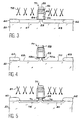
- Figures 7 and 8 show two examples of the results obtained on "minimal" structures, by playing on the angle of inclination of the implantation beam n + , the dose, the implantation energy, the oxidation time. and the size of the grid.
- a metallic material on the structure obtained at the Figure 6, for example by chemical phase deposition vapor (CVD), this metallic material with potential of extraction which places the Fermi level of this metallic material towards the middle of the strip prohibited silicon.
- CVD chemical phase deposition vapor
- the metallic material thus deposited exceeds the level of the insulating layer 58 in Si 3 N 4 .
- This metallic material is then polished, this layer 58 serving as a polishing stop layer.
- the metallic materials that represent the best compromise both from an electronic point of view that from the technological point of view for the realization source and drain areas are tungsten, the titanium nitride and titanium.
- Schottky diodes are produced using for example platinum, gold or palladium on the side n and titanium or aluminum on the p side.
- a MOS type transistor is thus obtained including a metal-insulator-semiconductor structure when we go from the source to the channel of transistor or drain to this channel the insulator from this structure allowing a tunnel effect.
- the canal region is only accessible by porters crossing the tunnel barrier of loads supplied by the source of the transistor.
- channel 95 of the transistor can be a slightly open volume on the substrate ( Figure 7) or a closed volume if this channel has a short length, not exceeding about 10 nm (figure 8).
- the transistor channel can be polarized by through the substrate.
- the control of the blocking voltage by the substrate is like in a MOS transistor classic.
- the length of the channel is greater than approximately 10 nm.
- This quantum well allows trapping Coulomb of charge carriers by confinement.
- MOS transistors to mono-carrier (mono-electron or mono-hole).
- This other manufacturing process is identical to the process according to the invention, allowing to obtain a MOS transistor on a substrate solid semiconductor ( Figures 3 to 9) except for concerns the achievement of source isolation and of the drain which is not necessary in the present case.
- the thickness of layer 102 is chosen large enough to prevent tunneling direct through this layer 102.
- the field isolation zones 60 and 62 share and across the grid area 71 for example by the LOCOS method.
- the recess 110 is between the zone 60 and the grid area 71 and the recess 112 is between the latter and zone 62.
- the recesses can be formed by isotropic etching of the silicon.
- They can also be formed by first implanting p + in the zones 106 and 108 of the silicon layer 104 (these zones being the counterparts of the zones 67 and 69 of FIG. 3), by means of a beam 105 appropriate ions, the substrate being inclined and rotated during this implantation, as we saw above.
- These layers may be nitride of silicon and are then formed by nitriding rapid thermal expansion of the silicon zone 14.
- They can also be made of silica and are then formed by rapid oxidation of the silicon 114.
- Figure 12 also shows very small layers 120 and 122 which are formed in silicon, respectively on the side of field isolation zones 60 and 62.
- Figure 13 is an enlarged view of the channel area 114 of the transistor that we are currently to train.
- This channel area 114 is separated from the recesses 110 and 112, which are designed to receive the source and drain zones, by the layers very thin insulators 116 and 118.
- This channel area 114 constitutes a volume inaccessible (from an electrical point of view) from substrate 100.
- This channel area 114 of the transistor constitutes a quantum well.
- Figure 14 schematically illustrates a another step allowing the formation of the transistor.
- this other step consists of depositing a metallic material, for example by chemical vapor deposition, on the structure of Figure 12, until this material exceeds the level of the insulating layer 58.
- this insulating layer 58 serving as a layer polishing stop.
- Figures 15 to 19 illustrate schematically steps of another conforming process to the invention, enabling a transistor to be obtained MOS with pseudo-SOI type structure.
- a thin deposit of silicon nitride is formed, for example by deposition chemical in vapor phase at low pressure ("low pressure chemical vapor deposition ”) in recesses 68 and 70 of this structure, in particular on the sides of these recesses, sides which are under layer 52.
- the thickness of this deposit on these sides is such as the passage of electrons in the part active of the transistor that we want to form is done by tunnel effect.
- This thickness is for example of the order from a few nanometers to 2.5 nanometers.
- Figure 15 also shows very small nitride layers of silicon 128 and 130 which remain after etching the silicon nitride at the ends of the recesses respectively located on the side of the isolation zones of field 60 and 62.
- the layers of localized silica as well obtained have the references 132 and 134 in the figure 16.
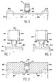
- Figures 17 and 18 (respectively counterparts in Figures 7 and 8) show the volume of monocrystalline silicon 138 intended to contain the channel of the transistor.
- This volume 138 is delimited by the layers very thin 124 and 128 allowing the tunnel effect.
- this volume communicates with the silicon substrate 50 monocrystalline by a very narrow area of this substrate.
- This very narrow area is bounded by the ends of layers 132 and 134, ends which face each other under layer 52.
- This communication allows training a MOS transistor controlled via the substrate 50.
- the volume of silicon 138 intended to contain the channel of transistor, is electrically isolated from substrate 50.
- This volume 138 also delimited by very thin layers 124 and 126 provides a then quantum.
- Figure 19 schematically illustrates the formation of the source and drain zones 92 and 94 of the transistor.
- This training takes place by filing a metallic material then polishing of it until level of the insulating layer 58 (which serves as a layer polishing), as already explained.
- Figure 22 schematically illustrates completion of the transistor resulting from the process corresponding to Figures 20 and 21 (deposition of the material metallic allowing the formation of the source zones and drain 92 and 94).
- Figure 23 is a sectional view transverse and schematic of another transistor according to the invention, formed on a type structure SOI.
- this transistor of the figure 23 is obtained as explained by making reference to Figures 15 to 19 or using the variant explained in the description of Figures 20 and 21, except that the use of a structure SOI initial does not require localized oxidation having allowed the formation of layers 132 and 134.
- a gate contact is subsequently formed to complete the transistor.
- This application relates to transistors partially shown in Figures 8 and 18, the channel of which is a closed volume.
- Pseudo-SOI type structures shown in Figures 8 and 18 can be used as a non-volatile memory point.
- V-shaped substrate 95 or 138 area then plays the role of storage capacity of the point memory.
Claims (18)
- Transistor des MOS-Typs, umfassend:wobei die Source- und Drain-Zonen vom Kanal jeweils durch elektrisch isolierende Zonen (88, 90; 116, 118; 124, 126; 142, 144) getrennt sind, die ausreichend dünn sind, um den Durchgang von Ladungsträgern von der Source-Zone zur Drain-Zone durch den Kanal hindurch mittels Tunneleffekt zu ermöglichen,ein Halbleitersubstrat (50 ; 100),eine Gate-Zone (71),einen Halbleiterkanal (95 ; 114 ; 138), unter der Gate-Zone befindlich und von dieser elektrisch isoliert, undeine Source-Zone und eine Drain-Zone (92, 94), die sich beiderseits der Gate-Zone und des Kanals befinden und elektrisch vom Substrat und der Gate-Zone isoliert sind,
dadurch gekennzeichnet, dass jede der Zonen von Source und Drain vom Substrat durch eine elektrisch isolierende Schicht getrennt ist, deren Dicke ausreichend groß ist, um jeden Durchgang von Ladungsträgern durch diese isolierende Schicht hindurch zu verhindern. - Transistor des MOS-Typs nach Anspruch 1, dadurch gekennzeichnet, dass jede der Source- und Drain-Zonen (92, 94) aus einem metallischen Material ist.
- Transistor des MOS-Typs nach einem der Ansprüche 1 und 2, dadurch gekennzeichnet, dass der Kanal vom Substrat (50; 100) elektrisch isoliert ist.
- Transistor des MOS-Typs nach einem der Ansprüche 1 und 2, dadurch gekennzeichnet, dass der Kanal mit dem Substrat (50; 100) elektrischen Kontakt hat mittels einer schmalen Zone dieses Substrats, wobei diese Zone kleiner als der Kanal ist.
- Transistor des MOS-Typs nach einem der Ansprüche 1 bis 4, dadurch gekennzeichnet, dass das Substrat (50; 100) und der Kanal (95; 114; 138) aus Silicium sind.
- Transistor des MOS-Typs nach Anspruch 5, dadurch gekennzeichnet, dass die ausreichend dünnen isolierenden Schichten aus Siliciumdioxid sind.
- Transistor des MOS-Typs nach Anspruch 5, dadurch gekennzeichnet, dass die ausreichend dünnen isolierenden Schichten aus Siliciumnitrid sind.
- Transistor des MOS-Typs nach einem der Ansprüche 5 bis 7, dadurch gekennzeichnet, dass die isolierende Schicht, die jede der Source- und Drain-Zonen (92, 94) vom Substrat trennt, eine Siliciumdioxidschicht (84; 86; 132, 134) ist.
- Transistor des MOS-Typs nach einem der Ansprüche 1 bis 7, dadurch gekennzeichnet, dass die Source-Zone, die Drain-Zone und der Kanal vom Substrat durch eine sehr dicke, elektrisch isolierende Schicht (102) getrennt sind.
- Verfahren zur Herstellung des MOS-Transistors nach Anspruch 1, wobei dieses Verfahren dadurch gekennzeichnet ist, dass es die folgenden Schritte umfasst:man bildet eine das Substrat (50), die aktive Zone und - beiderseits von dieser - zwei Feldisolationszonen (60, 62) und die Gate-Zone (71) umfassende Struktur, wobei die aktive Zone die Zone umfasst, in der die Source, der Drain und die unter dem Gate befindliche Kanalregion ausgebildet sind,man bildet in dem Substrat zwei Aussparungen (110, 112), die eine zwischen einer der Feldisolationszonen und der Gate-Zone und die andere zwischen dieser Gate-Zone und der anderen Feldisolationszone, wobei die jeweiligen Flanken der Aussparungen, die am nächsten bei der Gate-Zone sind, sich unter dieser befinden,man bildet auf den genannten Flanken ausreichend dünne elektrisch isolierende Schichten (88, 90), die die Source- und Drain-Zonen vom Kanal trennen und so dünn sind, dass sie den Durchgang von Ladungsträgern von der Source-Zone zur Drain-Zone durch den Kanal hindurch mittels Tunneleffekt ermöglichen, und man bildet auf dem Boden der Aussparungen die genannten isolierenden Schichten (84, 86), deren Dicke ausreichend groß ist, um jeden Durchgang von Ladungsträgern durch diese isolierende Schicht zu verhindern, undman bildet die Source- und Drain-Zonen (92, 94) jeweils in diesen Aussparungen.
- Verfahren nach Anspruch 10 zur Herstellung des Transistors nach Anspruch 8, dadurch gekennzeichnet, dass zuerst die genannten ausreichend dünnen isolierenden Schichten ausgebildet werden und anschließend die genannten Siliciumdioxid-Schichten (84, 86) gebildet werden, indem Zonen des Substrats am Boden der Aussparungen durch Verunreinigungen dotiert werden, die eine schnelle Oxidation des Substrats ermöglichen, sodann indem man die derart dotierten Zonen oxidiert.
- Verfahren nach Anspruch 11, dadurch gekennzeichnet, dass die ausreichend dünnen isolierenden Schichten aus Siliciumdioxid oder aus Siliciumnitrid sind.
- Verfahren nach Anspruch 10 zur Herstellung des Transistors nach Anspruch 8. dadurch gekennzeichnet, dass man zur Bildung der genannten ausreichend dünnen isolierenden Schichten und der genannten Siliciumdioxid-Schichten (84, 86) in den Aussparungen Siliciumnitrid abscheidet, man das abgeschiedene Siliciumnitrid beseitigt, wobei die Beseitigung auf den Flanken nicht stattfindet, um die genannten ausreichend dünnen isolierenden Schichten zu bilden, und man Zonen des Substrats auf dem Boden der Aussparungen oxidiert, um die genannten Siliciumdioxid-Schichten zu bilden.
- Verfahren nach Anspruch 10 zur Herstellung des Transistors nach Anspruch 8, dadurch gekennzeichnet, dass man zur Bildung der genannten ausreichend dünnen isolierenden Schichten und der genannten Siliciumdioxid-Schichten (84, 86) in den Aussparungen Siliciumnitrid abscheidet, man das abgeschiedene Siliciumnitrid beseitigt, wobei die Beseitigung auf den genannten Flanken nicht stattfindet, man Zonen des Substrats auf dem Boden der Aussparungen oxidiert, man das Nitrid auf den genannten Flanken beseitigt und man diese Flanken oxidiert, um die genannten ausreichend dünnen Siliciumdioxid-Schichten zu bilden.
- Verfahren zur Herstellung des MOS-Transistors nach Anspruch 9, dadurch gekennzeichnet, wobei dieses Verfahren dadurch gekennzeichnet ist, dass es die folgenden Schritte umfasst:man bildet eine Struktur, die eine das Substrat (100), die sehr dicke, jeden Durchgang von Ladungsträgern verhindernde Isolierschicht (102), auf dieser eine Halbleiterschicht (104), die aktive Zone und - beiderseits von dieser - zwei Feldisolationszonen (60, 62) und die Gate-Zone (71) umfasst, wobei die aktive Zone die Zone umfasst, in der die Source, der Drain und die unter dem Gate befindliche Kanalregion ausgebildet sind,man bildet in der genannten Halbleiterschicht zwei Aussparungen (110, 112), die eine zwischen einer der Feldisolationszonen und der Gate-Zone und die andere zwischen dieser Gate-Zone und der anderen Feldisolationszone, wobei die jeweiligen Flanken der Aussparungen, die am nächsten bei der Gate-Zone sind, sich unter dieser befinden,man bildet auf den genannten Flanken ausreichend dünne elektrisch isolierende Schichten (116, 118), die die Source- und Drain-Zonen vom Kanal trennen und so dünn sind, dass sie den Durchgang von Ladungsträgern von der Source-Zone zur Drain-Zone durch den Kanal hindurch mittels Tunneleffekt ermöglichen, undman bildet die Source- und Drain-Zonen (92, 94) jeweils in diesen Aussparungen.
- Verfahren nach Anspruch 15 zur Herstellung des Transistors nach Anspruch 5, wobei die sehr dicke Schicht aus Siliciumdioxid ist, dadurch gekennzeichnet, dass die genannten ausreichend dünnen isolierenden Schichten aus Siliciumdioxid oder aus Siliciumnitrid sind.
- Verfahren nach Anspruch 15 zur Herstellung des Transistors nach Anspruch 5, wobei die sehr dicke Schicht aus Siliciumdioxid ist, dadurch gekennzeichnet, dass man, um die genannten ausreichend dünnen isolierenden Schichten (116, 118) zu bilden, in den Aussparungen Siliciumnitrid abscheidet und das so abgeschiedene Nitrid beseitigt, wobei die Beseitigung auf den genannten Flanken nicht stattfindet.
- Anwendung des MOS-Transistors nach Anspruch 3 in den permanenten bzw. energieunabhängigen Speichern, wobei der Kanal des Transistors ein geschlossenes Volumen ist.
Applications Claiming Priority (3)
| Application Number | Priority Date | Filing Date | Title |
|---|---|---|---|
| FR9607444A FR2749977B1 (fr) | 1996-06-14 | 1996-06-14 | Transistor mos a puits quantique et procedes de fabrication de celui-ci |
| FR9607444 | 1996-06-14 | ||
| PCT/FR1997/001075 WO1997048135A1 (fr) | 1996-06-14 | 1997-06-13 | Transistor mos a puits quantique et procedes de fabrication de celui-ci |
Publications (2)
| Publication Number | Publication Date |
|---|---|
| EP0852814A1 EP0852814A1 (de) | 1998-07-15 |
| EP0852814B1 true EP0852814B1 (de) | 2002-09-25 |
Family
ID=9493075
Family Applications (1)
| Application Number | Title | Priority Date | Filing Date |
|---|---|---|---|
| EP97929353A Expired - Lifetime EP0852814B1 (de) | 1996-06-14 | 1997-06-13 | Quantentopf-mos-transistor und verfahren zur herstellung |
Country Status (7)
| Country | Link |
|---|---|
| US (1) | US6091076A (de) |
| EP (1) | EP0852814B1 (de) |
| JP (1) | JPH11510967A (de) |
| KR (1) | KR19990036252A (de) |
| DE (1) | DE69715802T2 (de) |
| FR (1) | FR2749977B1 (de) |
| WO (1) | WO1997048135A1 (de) |
Families Citing this family (48)
| Publication number | Priority date | Publication date | Assignee | Title |
|---|---|---|---|---|
| US6887762B1 (en) * | 1998-11-12 | 2005-05-03 | Intel Corporation | Method of fabricating a field effect transistor structure with abrupt source/drain junctions |
| FR2797349B1 (fr) * | 1999-08-04 | 2002-03-08 | X Ion | Composant a elements mono-electron et dispositif quantique, ainsi que procede industriel de realisation et reacteur multichambres de mise en oeuvre |
| US6339005B1 (en) * | 1999-10-22 | 2002-01-15 | International Business Machines Corporation | Disposable spacer for symmetric and asymmetric Schottky contact to SOI MOSFET |
| US6303479B1 (en) * | 1999-12-16 | 2001-10-16 | Spinnaker Semiconductor, Inc. | Method of manufacturing a short-channel FET with Schottky-barrier source and drain contacts |
| US6472232B1 (en) * | 2000-02-22 | 2002-10-29 | International Business Machines Corporation | Semiconductor temperature monitor |
| FR2806832B1 (fr) * | 2000-03-22 | 2002-10-25 | Commissariat Energie Atomique | Transistor mos a source et drain metalliques, et procede de fabrication d'un tel transistor |
| FR2810792B1 (fr) | 2000-06-22 | 2003-07-04 | Commissariat Energie Atomique | Transistor mos vertical a grille enterree et procede de fabrication de celui-ci |
| WO2002043109A2 (de) * | 2000-11-21 | 2002-05-30 | Infineon Technologies Ag | Verfahren zum herstellen eines planaren feldeffekttransistors und planarer feldeffekttransistor |
| FR2818439B1 (fr) * | 2000-12-18 | 2003-09-26 | Commissariat Energie Atomique | Procede de fabrication d'un ilot de matiere confine entre des electrodes, et applications aux transistors |
| US6566680B1 (en) * | 2001-01-30 | 2003-05-20 | Advanced Micro Devices, Inc. | Semiconductor-on-insulator (SOI) tunneling junction transistor |
| JP4789362B2 (ja) * | 2001-07-25 | 2011-10-12 | 富士機械製造株式会社 | 基板保持装置 |
| DE10137217A1 (de) * | 2001-07-30 | 2003-02-27 | Infineon Technologies Ag | Steg-Feldeffekttransistor und Verfahren zum Herstellen eines Steg-Feldeffekttransistors |
| US20030134486A1 (en) * | 2002-01-16 | 2003-07-17 | Zhongze Wang | Semiconductor-on-insulator comprising integrated circuitry |
| US7084423B2 (en) | 2002-08-12 | 2006-08-01 | Acorn Technologies, Inc. | Method for depinning the Fermi level of a semiconductor at an electrical junction and devices incorporating such junctions |
| US7902029B2 (en) * | 2002-08-12 | 2011-03-08 | Acorn Technologies, Inc. | Process for fabricating a self-aligned deposited source/drain insulated gate field-effect transistor |
| US6833556B2 (en) | 2002-08-12 | 2004-12-21 | Acorn Technologies, Inc. | Insulated gate field effect transistor having passivated schottky barriers to the channel |
| KR100499956B1 (ko) * | 2002-10-24 | 2005-07-05 | 전자부품연구원 | 양자채널이 형성된 모스펫을 이용한 포토디텍터 및 그제조방법 |
| US6657223B1 (en) | 2002-10-29 | 2003-12-02 | Advanced Micro Devices, Inc. | Strained silicon MOSFET having silicon source/drain regions and method for its fabrication |
| JP2004241755A (ja) * | 2003-01-15 | 2004-08-26 | Renesas Technology Corp | 半導体装置 |
| US6964911B2 (en) * | 2003-09-23 | 2005-11-15 | Freescale Semiconductor, Inc. | Method for forming a semiconductor device having isolation regions |
| US20050139860A1 (en) * | 2003-10-22 | 2005-06-30 | Snyder John P. | Dynamic schottky barrier MOSFET device and method of manufacture |
| FR2868209B1 (fr) * | 2004-03-25 | 2006-06-16 | Commissariat Energie Atomique | Transistor a effet de champ a canal en carbone diamant |
| US20060091467A1 (en) * | 2004-10-29 | 2006-05-04 | Doyle Brian S | Resonant tunneling device using metal oxide semiconductor processing |
| KR100592740B1 (ko) * | 2004-12-03 | 2006-06-26 | 한국전자통신연구원 | 쇼트키 장벽 관통 단전자 트랜지스터 및 그 제조방법 |
| FR2879020B1 (fr) * | 2004-12-08 | 2007-05-04 | Commissariat Energie Atomique | Procede d'isolation de motifs formes dans un film mince en materiau semi-conducteur oxydable |
| US20060125121A1 (en) * | 2004-12-15 | 2006-06-15 | Chih-Hsin Ko | Capacitor-less 1T-DRAM cell with Schottky source and drain |
| FR2883101B1 (fr) * | 2005-03-08 | 2007-06-08 | Centre Nat Rech Scient | Transistor mos nanometrique a rapport maximise entre courant a l'etat passant et courant a l'etat bloque |
| US7244659B2 (en) * | 2005-03-10 | 2007-07-17 | Micron Technology, Inc. | Integrated circuits and methods of forming a field effect transistor |
| US20070194353A1 (en) * | 2005-08-31 | 2007-08-23 | Snyder John P | Metal source/drain Schottky barrier silicon-on-nothing MOSFET device and method thereof |
| US7557002B2 (en) * | 2006-08-18 | 2009-07-07 | Micron Technology, Inc. | Methods of forming transistor devices |
| KR100800508B1 (ko) * | 2006-12-27 | 2008-02-04 | 재단법인 서울대학교산학협력재단 | 자기 정렬된 트랜치를 갖는 단전자 트랜지스터 및 그제조방법 |
| US7989322B2 (en) | 2007-02-07 | 2011-08-02 | Micron Technology, Inc. | Methods of forming transistors |
| US7732285B2 (en) * | 2007-03-28 | 2010-06-08 | Intel Corporation | Semiconductor device having self-aligned epitaxial source and drain extensions |
| US20090001430A1 (en) * | 2007-06-29 | 2009-01-01 | International Business Machines Corporation | Eliminate notching in si post si-recess rie to improve embedded doped and instrinsic si epitazial process |
| JP4555358B2 (ja) * | 2008-03-24 | 2010-09-29 | 富士フイルム株式会社 | 薄膜電界効果型トランジスタおよび表示装置 |
| US8242542B2 (en) * | 2009-02-24 | 2012-08-14 | International Business Machines Corporation | Semiconductor switching device employing a quantum dot structure |
| WO2010113715A1 (ja) * | 2009-03-31 | 2010-10-07 | 日鉱金属株式会社 | 半導体装置の製造方法及び半導体装置 |
| US8313999B2 (en) | 2009-12-23 | 2012-11-20 | Intel Corporation | Multi-gate semiconductor device with self-aligned epitaxial source and drain |
| US8648426B2 (en) * | 2010-12-17 | 2014-02-11 | Seagate Technology Llc | Tunneling transistors |
| FR2970813B1 (fr) * | 2011-01-24 | 2013-09-27 | Commissariat Energie Atomique | Dispositif a effet de champ muni d'une zone barrière de diffusion de dopants localisée et procédé de réalisation |
| KR101292952B1 (ko) * | 2011-03-16 | 2013-08-02 | 삼성에스디아이 주식회사 | 전극조립체 및 이를 이용한 이차 전지 |
| CN103094338B (zh) * | 2011-11-01 | 2015-09-09 | 中国科学院微电子研究所 | 半导体器件及其制造方法 |
| US8816326B2 (en) * | 2011-11-01 | 2014-08-26 | Institute of Microelectronics, Chinese Academy of Sciences | Semiconductor device and manufacturing method thereof |
| JP6570115B2 (ja) * | 2015-07-24 | 2019-09-04 | 国立研究開発法人産業技術総合研究所 | 単電子トランジスタ及びその製造方法並びに集積回路 |
| FR3044824B1 (fr) * | 2015-12-08 | 2018-05-04 | Commissariat A L'energie Atomique Et Aux Energies Alternatives | Transistor sbfet ameliore et procede de fabrication correspondant |
| US9620611B1 (en) | 2016-06-17 | 2017-04-11 | Acorn Technology, Inc. | MIS contact structure with metal oxide conductor |
| FR3057105A1 (fr) * | 2016-10-05 | 2018-04-06 | Commissariat A L'energie Atomique Et Aux Energies Alternatives | Dispositif a boite(s) quantique(s) comportant des dopants localises dans une couche semi-conductrice mince |
| US10170627B2 (en) | 2016-11-18 | 2019-01-01 | Acorn Technologies, Inc. | Nanowire transistor with source and drain induced by electrical contacts with negative schottky barrier height |
Family Cites Families (17)
| Publication number | Priority date | Publication date | Assignee | Title |
|---|---|---|---|---|
| JPS5646557A (en) * | 1979-09-26 | 1981-04-27 | Chiyou Lsi Gijutsu Kenkyu Kumiai | Transistor |
| JPS5854668A (ja) * | 1981-09-29 | 1983-03-31 | Fujitsu Ltd | 電気的消去型読出し専用メモリおよびその製造方法 |
| US4712122A (en) * | 1984-07-26 | 1987-12-08 | Research Development Corp. | Heterojunction gate ballistic JFET with channel thinner than Debye length |
| JPS6163057A (ja) * | 1984-09-04 | 1986-04-01 | Nippon Telegr & Teleph Corp <Ntt> | Misfetとその製造方法 |
| JPS61188969A (ja) * | 1985-02-18 | 1986-08-22 | Matsushita Electric Ind Co Ltd | 薄膜トランジスタ |
| JPH0666467B2 (ja) * | 1985-12-27 | 1994-08-24 | 株式会社東芝 | 半導体装置 |
| JPS62160769A (ja) * | 1986-01-10 | 1987-07-16 | Hitachi Ltd | 薄膜トランジスタ素子 |
| US5043778A (en) * | 1986-08-11 | 1991-08-27 | Texas Instruments Incorporated | Oxide-isolated source/drain transistor |
| US5132755A (en) * | 1989-07-11 | 1992-07-21 | Oki Electric Industry Co. Ltd. | Field effect transistor |
| JP3194941B2 (ja) * | 1990-03-19 | 2001-08-06 | 富士通株式会社 | 半導体装置 |
| JPH04335538A (ja) * | 1991-05-10 | 1992-11-24 | Mitsubishi Electric Corp | 半導体装置およびその製造方法 |
| JP3361135B2 (ja) * | 1991-12-20 | 2003-01-07 | テキサス インスツルメンツ インコーポレイテツド | 量子効果論理ユニットとその製造方法 |
| JPH0697435A (ja) * | 1992-09-11 | 1994-04-08 | Hitachi Ltd | Mos型半導体装置 |
| US5831294A (en) * | 1993-09-30 | 1998-11-03 | Sony Corporation | Quantum box structure and carrier conductivity modulating device |
| JP3635683B2 (ja) * | 1993-10-28 | 2005-04-06 | ソニー株式会社 | 電界効果トランジスタ |
| US5796119A (en) * | 1993-10-29 | 1998-08-18 | Texas Instruments Incorporated | Silicon resonant tunneling |
| US5731598A (en) * | 1995-06-23 | 1998-03-24 | Matsushita Electric Industrial Co. Ltd. | Single electron tunnel device and method for fabricating the same |
-
1996
- 1996-06-14 FR FR9607444A patent/FR2749977B1/fr not_active Expired - Fee Related
-
1997
- 1997-06-13 DE DE69715802T patent/DE69715802T2/de not_active Expired - Lifetime
- 1997-06-13 KR KR1019980700920A patent/KR19990036252A/ko not_active Application Discontinuation
- 1997-06-13 JP JP10501321A patent/JPH11510967A/ja active Pending
- 1997-06-13 EP EP97929353A patent/EP0852814B1/de not_active Expired - Lifetime
- 1997-06-13 US US09/011,626 patent/US6091076A/en not_active Expired - Lifetime
- 1997-06-13 WO PCT/FR1997/001075 patent/WO1997048135A1/fr not_active Application Discontinuation
Also Published As
| Publication number | Publication date |
|---|---|
| DE69715802T2 (de) | 2003-05-15 |
| US6091076A (en) | 2000-07-18 |
| WO1997048135A1 (fr) | 1997-12-18 |
| FR2749977A1 (fr) | 1997-12-19 |
| KR19990036252A (ko) | 1999-05-25 |
| EP0852814A1 (de) | 1998-07-15 |
| FR2749977B1 (fr) | 1998-10-09 |
| DE69715802D1 (de) | 2002-10-31 |
| JPH11510967A (ja) | 1999-09-21 |
Similar Documents
| Publication | Publication Date | Title |
|---|---|---|
| EP0852814B1 (de) | Quantentopf-mos-transistor und verfahren zur herstellung | |
| EP0426250B1 (de) | Verfahren zur Herstellung eines MIS-Transistor-Bauelementes mit einem Gitter, welches über geringdotierte Teile der Source- und Drain-Gebiete herausragt | |
| FR2806832A1 (fr) | Transistor mos a source et drain metalliques, et procede de fabrication d'un tel transistor | |
| FR2819341A1 (fr) | Procede d'integration d'une cellule dram | |
| JPH11163329A (ja) | 半導体装置およびその製造方法 | |
| FR2652448A1 (fr) | Procede de fabrication d'un circuit integre mis haute tension. | |
| FR3060841A1 (fr) | Procede de realisation d'un dispositif semi-conducteur a espaceurs internes auto-alignes | |
| EP2279520A2 (de) | Verfahren zur herstellung komplementärer p- und n-mosfet-transistoren, elektronische vorrichtung mit derartigen transistoren und prozessor mit mindestens einer derartigen vorrichtung | |
| EP2680311A1 (de) | Tunneleffekttransistor | |
| FR2795554A1 (fr) | Procede de gravure laterale par trous pour fabriquer des dis positifs semi-conducteurs | |
| US20100027355A1 (en) | Planar double gate transistor storage cell | |
| EP2120258B1 (de) | Herstellungsverfahren eines Transistors mit Metallquelle und -abfluss | |
| WO2001099197A1 (fr) | Transistor mos vertical a grille enterree et procede de fabrication de celui-ci | |
| FR2818012A1 (fr) | Dispositif semi-conducteur integre de memoire | |
| CA2399115C (fr) | Transistor mos pour circuits a haute densite d'integration | |
| EP1271657A1 (de) | Integrierte Halbleiterspeicheranordnung des DRAM-Typs und Verfahren zur Herstellung | |
| FR2791178A1 (fr) | NOUVEAU DISPOSITIF SEMI-CONDUCTEUR COMBINANT LES AVANTAGES DES ARCHITECTURES MASSIVE ET soi, ET PROCEDE DE FABRICATION | |
| US11158715B2 (en) | Vertical FET with asymmetric threshold voltage and channel thicknesses | |
| EP1517377A1 (de) | Bipolartransistor | |
| FR3035265A1 (fr) | Procede de fabrication de transistors soi pour une densite d'integration accrue | |
| EP0607075B1 (de) | Elektronisches Halbleiterbauelement mit negativem dynamischem Widerstand und entsprechende Verwendungs- und Herstellungsverfahren | |
| FR3109017A1 (fr) | PROCÉDÉ DE FABRICATION D’UNE PUCE À CIRCUIT INTÉGRÉ sur SeOI | |
| EP3671836A1 (de) | 3d schaltung mit einem mesa-isolation für den grundplattenbereich | |
| FR3017744A1 (fr) | Circuit integre comportant des transistors a tensions de seuil distinctes | |
| FR3136109A1 (fr) | Dispositif semiconducteur du type silicium sur isolant et procédé de fabrication correspondant |
Legal Events
| Date | Code | Title | Description |
|---|---|---|---|
| PUAI | Public reference made under article 153(3) epc to a published international application that has entered the european phase |
Free format text: ORIGINAL CODE: 0009012 |
|
| 17P | Request for examination filed |
Effective date: 19980120 |
|
| AK | Designated contracting states |
Kind code of ref document: A1 Designated state(s): DE FR GB IT |
|
| 17Q | First examination report despatched |
Effective date: 19991227 |
|
| GRAG | Despatch of communication of intention to grant |
Free format text: ORIGINAL CODE: EPIDOS AGRA |
|
| GRAG | Despatch of communication of intention to grant |
Free format text: ORIGINAL CODE: EPIDOS AGRA |
|
| GRAG | Despatch of communication of intention to grant |
Free format text: ORIGINAL CODE: EPIDOS AGRA |
|
| GRAH | Despatch of communication of intention to grant a patent |
Free format text: ORIGINAL CODE: EPIDOS IGRA |
|
| GRAH | Despatch of communication of intention to grant a patent |
Free format text: ORIGINAL CODE: EPIDOS IGRA |
|
| GRAA | (expected) grant |
Free format text: ORIGINAL CODE: 0009210 |
|
| AK | Designated contracting states |
Kind code of ref document: B1 Designated state(s): DE FR GB IT |
|
| REG | Reference to a national code |
Ref country code: GB Ref legal event code: FG4D Free format text: NOT ENGLISH |
|
| REF | Corresponds to: |
Ref document number: 69715802 Country of ref document: DE Date of ref document: 20021031 |
|
| GBT | Gb: translation of ep patent filed (gb section 77(6)(a)/1977) |
Effective date: 20021230 |
|
| PLBE | No opposition filed within time limit |
Free format text: ORIGINAL CODE: 0009261 |
|
| STAA | Information on the status of an ep patent application or granted ep patent |
Free format text: STATUS: NO OPPOSITION FILED WITHIN TIME LIMIT |
|
| 26N | No opposition filed |
Effective date: 20030626 |
|
| PGFP | Annual fee paid to national office [announced via postgrant information from national office to epo] |
Ref country code: IT Payment date: 20110625 Year of fee payment: 15 |
|
| PG25 | Lapsed in a contracting state [announced via postgrant information from national office to epo] |
Ref country code: IT Free format text: LAPSE BECAUSE OF NON-PAYMENT OF DUE FEES Effective date: 20120613 |
|
| PGFP | Annual fee paid to national office [announced via postgrant information from national office to epo] |
Ref country code: GB Payment date: 20140617 Year of fee payment: 18 |
|
| PGFP | Annual fee paid to national office [announced via postgrant information from national office to epo] |
Ref country code: DE Payment date: 20140610 Year of fee payment: 18 |
|
| REG | Reference to a national code |
Ref country code: DE Ref legal event code: R119 Ref document number: 69715802 Country of ref document: DE |
|
| GBPC | Gb: european patent ceased through non-payment of renewal fee |
Effective date: 20150613 |
|
| PG25 | Lapsed in a contracting state [announced via postgrant information from national office to epo] |
Ref country code: DE Free format text: LAPSE BECAUSE OF NON-PAYMENT OF DUE FEES Effective date: 20160101 Ref country code: GB Free format text: LAPSE BECAUSE OF NON-PAYMENT OF DUE FEES Effective date: 20150613 |
|
| REG | Reference to a national code |
Ref country code: FR Ref legal event code: PLFP Year of fee payment: 20 |
|
| PGFP | Annual fee paid to national office [announced via postgrant information from national office to epo] |
Ref country code: FR Payment date: 20160708 Year of fee payment: 20 |