EP0848097B1 - Antriebsvorrichtung für die Fachbildeelemente von Webmaschinen - Google Patents
Antriebsvorrichtung für die Fachbildeelemente von Webmaschinen Download PDFInfo
- Publication number
- EP0848097B1 EP0848097B1 EP97120405A EP97120405A EP0848097B1 EP 0848097 B1 EP0848097 B1 EP 0848097B1 EP 97120405 A EP97120405 A EP 97120405A EP 97120405 A EP97120405 A EP 97120405A EP 0848097 B1 EP0848097 B1 EP 0848097B1
- Authority
- EP
- European Patent Office
- Prior art keywords
- drive device
- shaft
- shafts
- drive
- control unit
- Prior art date
- Legal status (The legal status is an assumption and is not a legal conclusion. Google has not performed a legal analysis and makes no representation as to the accuracy of the status listed.)
- Revoked
Links
- 230000033001 locomotion Effects 0.000 claims description 46
- 238000009941 weaving Methods 0.000 claims description 40
- 230000015654 memory Effects 0.000 claims description 10
- 230000001360 synchronised effect Effects 0.000 claims description 5
- 238000003780 insertion Methods 0.000 claims description 4
- 230000037431 insertion Effects 0.000 claims description 4
- 239000000463 material Substances 0.000 claims description 3
- 230000033764 rhythmic process Effects 0.000 claims description 3
- 230000001419 dependent effect Effects 0.000 claims description 2
- 230000007246 mechanism Effects 0.000 claims 6
- 230000002441 reversible effect Effects 0.000 claims 2
- 230000027455 binding Effects 0.000 description 46
- 238000009739 binding Methods 0.000 description 46
- 239000004744 fabric Substances 0.000 description 13
- 230000008878 coupling Effects 0.000 description 11
- 238000010168 coupling process Methods 0.000 description 11
- 238000005859 coupling reaction Methods 0.000 description 11
- 238000013461 design Methods 0.000 description 11
- 230000005540 biological transmission Effects 0.000 description 9
- 230000015572 biosynthetic process Effects 0.000 description 8
- 238000000034 method Methods 0.000 description 8
- 230000008569 process Effects 0.000 description 8
- 230000008859 change Effects 0.000 description 7
- 230000009467 reduction Effects 0.000 description 5
- 239000004753 textile Substances 0.000 description 5
- 230000006870 function Effects 0.000 description 4
- 238000012549 training Methods 0.000 description 4
- 235000014676 Phragmites communis Nutrition 0.000 description 3
- 230000001133 acceleration Effects 0.000 description 3
- 230000008901 benefit Effects 0.000 description 3
- 238000004519 manufacturing process Methods 0.000 description 3
- 238000013519 translation Methods 0.000 description 3
- 230000001276 controlling effect Effects 0.000 description 2
- 230000007547 defect Effects 0.000 description 2
- 238000010586 diagram Methods 0.000 description 2
- 239000000945 filler Substances 0.000 description 2
- 230000010354 integration Effects 0.000 description 2
- 238000000059 patterning Methods 0.000 description 2
- FGRBYDKOBBBPOI-UHFFFAOYSA-N 10,10-dioxo-2-[4-(N-phenylanilino)phenyl]thioxanthen-9-one Chemical compound O=C1c2ccccc2S(=O)(=O)c2ccc(cc12)-c1ccc(cc1)N(c1ccccc1)c1ccccc1 FGRBYDKOBBBPOI-UHFFFAOYSA-N 0.000 description 1
- 238000009825 accumulation Methods 0.000 description 1
- 230000003213 activating effect Effects 0.000 description 1
- 230000004913 activation Effects 0.000 description 1
- 238000013459 approach Methods 0.000 description 1
- 230000000903 blocking effect Effects 0.000 description 1
- 239000000969 carrier Substances 0.000 description 1
- 238000006243 chemical reaction Methods 0.000 description 1
- 238000004590 computer program Methods 0.000 description 1
- 230000000694 effects Effects 0.000 description 1
- 230000008030 elimination Effects 0.000 description 1
- 238000003379 elimination reaction Methods 0.000 description 1
- 238000004146 energy storage Methods 0.000 description 1
- 238000005516 engineering process Methods 0.000 description 1
- 239000000835 fiber Substances 0.000 description 1
- 238000012986 modification Methods 0.000 description 1
- 230000004048 modification Effects 0.000 description 1
- 238000012856 packing Methods 0.000 description 1
- 230000008092 positive effect Effects 0.000 description 1
- 230000001105 regulatory effect Effects 0.000 description 1
- 230000006641 stabilisation Effects 0.000 description 1
- 238000011105 stabilization Methods 0.000 description 1
- 230000003797 telogen phase Effects 0.000 description 1
- 238000012546 transfer Methods 0.000 description 1
Images



Classifications
-
- D—TEXTILES; PAPER
- D03—WEAVING
- D03C—SHEDDING MECHANISMS; PATTERN CARDS OR CHAINS; PUNCHING OF CARDS; DESIGNING PATTERNS
- D03C13/00—Shedding mechanisms not otherwise provided for
- D03C13/02—Shedding mechanisms not otherwise provided for with independent drive motors
- D03C13/025—Shedding mechanisms not otherwise provided for with independent drive motors with independent frame drives
-
- D—TEXTILES; PAPER
- D03—WEAVING
- D03C—SHEDDING MECHANISMS; PATTERN CARDS OR CHAINS; PUNCHING OF CARDS; DESIGNING PATTERNS
- D03C3/00—Jacquards
- D03C3/24—Features common to jacquards of different types
- D03C3/32—Jacquard driving mechanisms
- D03C3/36—Griffe operating mechanisms
Definitions
- the invention relates to a drive device for the shedding elements of weaving machines, in particular double-pile weaving machines as shafts, knife boxes or the like, depending on the weaving rhythm a lifting movement in changing directions relative to the weft insertion plane on the strands that guide the warp threads constantly or temporarily, alternating according to the pattern, directly or via links are coupled, with each shedding element for Purpose of their drive in the stroke direction, assigned a controllable motor is, the drive movement of the motors on the respective shedding element is transmitted and wherein the control computer program memory are assigned for the control of the subject image elements.
- Drive devices of the type mentioned are for driving the shafts a weaving machine by DE-Gbm 87 10 997.2 and further by DE 37 21 932 C2 became known.
- the drive device for the shafts described in these documents has an eccentric shaft which contains a plurality of drive cam disks for each of the shafts. Depending on the position of the shaft in the compartment, these cams can be equipped with different forms of movement between the end positions of the shafts. These different forms of movement relate to the size of the stroke and the law of movement between the end positions.
- the eccentric shaft is driven with the aid of a motor which can be regulated via a motor control. On the one hand, this motor control ensures synchronization with the main shaft of the weaving machine. On the other hand, this motor control also serves to regulate the drive speed of the eccentric shaft for the purpose of changing the changing speed.
- This drive device for the dobby can also be operated independently of the main drive of the weaving machine. If weft breaks occur, the position of the shafts after switching a clutch is brought into a position in which the broken shot can be removed and a new shot can be inserted by controlling the dobby.
- the assignment of the shafts to the individual cams must be changed. This can be done manually in a manner known per se or - automatically controlled by couplings. If the repeat size is changed, changing the cam disks is often unavoidable.
- the respective size of the shaft stroke is set either by a fixed assignment of the cam disc or by a design of the translation of the coupling links to the shafts. Changing the stroke size from a textile technology perspective is only possible with a considerable amount of work.
- the generic device also does not allow, depending on the type of binding, to differentiate the zero crossing of the warp threads when changing the shed. An accumulation of the warp threads in this area can lead to stapling the threads with each other and thus to a locked Guide compartment, the warp thread breaks when the weft is inserted and thus machine downtimes caused.
- JP 04 153342 A and JP 04 241130 A describe drive devices for the shafts of a weaving machine, in which a drive motor is assigned to each shaft. During intermittent operation, each of these drive motors drives a cam carrier, which in turn controls the lifting movement of the shafts. The drive motors can optionally be stopped in the limit positions of the cam lifting movement and switched on again according to the pattern. This allows you to implement different bindings, controlled by switching processes. However, even in this case it is not possible to change the stroke size, to vary the zero crossing, to carry out different movement sequences during the change of subject or to carry out certain control processes to remedy thread breaks.
- the aim of this arrangement is to assign a control to the servomotors for the rational use of energy, which makes it possible to store the electrical energy released during braking processes and to use this again during acceleration processes to drive other linear motors.
- the problems of friction and loading of the shedding elements due to the threads to be stretched are not taken into account in this context. This approach requires that the frictional forces in any transmission members that may be present be avoided as completely as possible and that the tensioning forces of the threads to be tensioned be disregarded.
- DE 689 21 940 T2 (EP 0 353 005 B1) is a control device known for the strands of weaving machines. After Teaching this document is assigned to each strand a linear motor, the Anchor is connected to the strand by a cord. The cord will tensioned by means of a spring which drives the linear motor is directed against. The linear motors are after one, from the textile Pattern specific control program activated and with an adjustable Energy fed and by a sensor at the end of the given Hubes shut down again. The stroke in the opposite direction is left to the preloaded spring.
- Such a control device is particularly unsuitable for carpet weaving machines with a large number of warp threads to be controlled differently per unit area.
- the necessary number of linear motors cannot be positioned in the area of the specialist training bodies in view of their low efficiency and the spatial size required as a result. If an extremely high packing density of the linear motors is ensured, then there are unsolvable problems in dissipating the heat released there (linear motors have an efficiency of about 60%).
- the linear motors which have to hold their strand in an extreme position against the spring force at rest, absorb a very large amount of energy. This makes the entire drive inefficient.
- the object of the present invention is to generate and transmit the drive movements for each shed forming element of a double-carpet weaving machine in such a way that different weave repeats are possible with detents of any length in different shed levels, with different stroke sizes and different movement sequences during the shed change with rational use of energy. It is also desirable that, depending on the textile technological conditions in the event of weft breakage, warp breakage and when the weaving machine is at a standstill for a longer period of time, the specialist positions can be guaranteed for other reasons while the machine is at a standstill and thus optimal operating options and optimal effects secure with regard to the woven goods.
- this object is ensured by the combination of the specialist image drive defined in claim 1.
- the holding takes place to a considerable extent through the transmission properties of the reduction gear when the load is entered on the shedding element and a movement on the motor is to be avoided.
- the shedding elements loaded by the tensioned warp threads - due to the greater forces required to overcome the translation forces acting in this direction - can hardly move the armatures of the motors. Only a small electrical holding torque is required on the motor so that it can be held in its current position.
- the control of the motors depending on their current position and depending on the respective position of the main shaft according to a programmed motion law enables - in contrast to the known state of the art - an exact and synchronous movement of the field elements in every phase of the change of subject. With this type of control, complex control processes starting from the specified end position can be avoided.
- Such a positively controlled drive for the shafts or knife boxes of a double pile weaving machine on the one hand enables the required high level of functional reliability and reliability in the extreme load in continuous operation and on the other hand creates almost unlimited variability.
- the claim 2 describes the optimal design for the transmission of Rotary movement of the motor on the up and down movable shafts.
- a toothed belt transmission according to claim 5 is recommended if one predominantly works according to the "closed subject" principle.
- the design of the drive according to claim 6 is particularly suitable for the drive of knife boxes and carriers for the finger rakes.
- program memories for controlling the motors according to claim 8 allows for different binding variants staggered crossing of the middle compartment level (zero crossing). On this prevents possible warping of warp threads. Also in The end positions of the specialist stroke can be controlled in such positions which the threads do not interfere with each other.
- the description of the invention is intended to be based on a double-carpet weaving machine.
- Machines of this type regularly have a working width of about 4 m.
- the gripper bar drives are located on the side of such a machine, so that the frame of the weaving machine projects beyond the working width on both sides by at least half the working width.
- the shafts S (referred to in their entirety here) of this weaving machine have a large length depending on the working width. As a result, it is necessary to transmit the drive movement to the frame of several sections.
- the shafts S of the weaving machine are used here to guide the threads of the binding chain BO, BU and the filling chain FO, FU not selected in accordance with the pattern in connection with the weft insertion for the production of the respective basic goods.
- the shafts are designated in their entirety with S. Numbers 1 to 6 are used to describe how individual shafts work.
- the pile thread guides which can be controlled by a jacquard device are also involved in the formation of a double-carpet weaving machine.
- each shaft frame or simply put, each shaft 1 ... 6 is assigned three angle levers 122 which drive the shafts 1 ... 6 in the vertical direction via a coupling 121.
- the angle levers 122 are positively drive-connected to one another by a drive rail 123 per shaft 1, which extends over a large part of the machine.
- This drive rail 123 is preferably driven outside the working area of the weaving machine via a drive lever 124 assigned to it.
- This is in turn connected via a coupling 125 to the nut 131 of a ball screw drive 13.
- the ball screw 132 is coupled directly or via a coupling to the axis of the motor 14.
- Such a ball screw gear 13 is assigned to each drive lever 124, which is assigned to a shaft 1 ... 6.
- Each ball screw spindle 132 is driven by a separate position-oriented controllable motor 141, 142, 143, 144, 145, 146.
- an IGR incremental encoder
- a central control computer 8 coordinates the separate control units 151, 152, 153, 154, 155, 156.
- This control computer has inputs for receiving synchronization signals from the encoder 81 on the main shaft HW of the machine.
- the control computer has inputs that are connected to the weft guard SW and inputs that take information or impulses from the warp guard KW1 .... KW4.
- These warp monitors are assigned to the warp threads in groups according to their function (preferably shaft-wise). This assignment primarily serves the purpose that the respective warp thread system, in which a warp thread break was found, to terminate the technical balance in a position when the machine is stopped, which ensures optimum operation when the warp thread break is eliminated.
- an operating unit 82 which is the control computer in a manner known per se 8 is assigned, preferably complex programs enter, select or correct.
- FIGS. 8 to 14 Seven of these basic weave variants are shown in FIGS. 8 to 14 in two ways of representation.
- the illustration on the left shows a schematic cross section through the upper fabric of the double carpet fabric along the warp threads.
- the right-hand illustration shows the movement diagram (s) of the respective shaft 1 ... 4 of the corresponding binding chain BO, BU.
- the distance between two adjacent vertical lines indicates the distance between two specialist representatives in two successive tours.
- the top line symbolizes the top compartment O, the middle line the middle compartment M and the bottom line the bottom compartment U.
- the binding warp thread BO of the upper fabric is primarily followed here.
- Fig. 8 shows a 1-thread binding chain BO3 in plain weave in a Carpet binding for 2-weft / 2-turn with a thin pile row density.
- the rips 2/4 weave shown in FIG. 10 shows a two-thread binding chain BO1, BO2.
- the binding chains BO1, BO2 alternate after every 4th tour. This binding is only rarely used because the dead poles are not integrated into the basic product.
- the binding shown in Fig. 11 is called Rips-2/2 (4-turn). They are used for the so-called AT binding, in which 2 shots are alternately entered in the upper fabric in a first tour and then 2 shots in the lower fabric in a second tour.
- FIG. 12 Another variant of the Rips 2/2 binding is shown in FIG. 12.
- This Binding is used for 2-shot, 2-turn bindings for larger ones Pole densities up to 100 pole rows / dm. Tie in such pile fabrics regularly all pile threads over the back shot.
- the advantage of this In addition to a high stability of the basic fabric, fabric consists in one reliable and stable integration of all pile threads P, all of them protrude vertically from their basic goods.
- the weave shown in Fig. 13 is regularly used for the basic carpet weave 3-shot / 3-speed and 2-shot / 3-speed.
- the two-ply Binding chain BO1, BO2 is alternately preferably 3 times bound high and 3 times low.
- the basic weave is used for carpets with a very high pile density according to Fig. 14. It is called Rips-2/4 (8-turn). she is comparable to the binding in FIG. 13.
- the binding chains BO1, BO2; BU 1, BU2 bind alternately 4 times high and 4 times low.
- pile threads P are alternately once on the inside weft and once tied to the back shot.
- An essential feature should be that the threads are in the range of motion the gripper bars on the one hand very tight and on the other hand very should be stable. It is therefore advisable to use the stable Filling chains FO, FU or the sufficiently stable binding warp threads BO, BU regularly very close to the gripper rails GO, GU.
- the pile warp threads P which, on the other hand, are relatively loose and puffy, should regularly behind these stable warp threads - based on the hook rails - be led.
- a zone M1 is provided between the two compartments.
- the group-controlled warp threads - namely the binding warp threads BO, BU and the filling chains FO, FU of the upper and lower goods are with the out front designated shafts 1 ... 6 (S). They are because of their, in usually smaller strokes arranged behind the jacquard strands JL.
- the invention now intends, in particular the middle passage of the Binding chain BO, BU and the filling chain FO, FU - based on the pile warp threads P and their movement - staggered so that within one Chores no more than two threads at a time in the middle of the field encounter (small arrow).
- each individual motor 141, 142, 143, 144, 145, 146 drives a shaft 1, 2, 3, 4, 5, 6, the stroke size, the position of the stroke and the center passage when changing subjects through a program in be specified in a very specific way.
- each of these motors 141, 142, 143, 144, 145, 146 a new, complex program prepared for this purpose and to control them in a manner known per se synchronously with the main shaft.
- This program can either be changed by entering changed program memories or by activating and calling up internal memories according to the program.
- These motors 141, 142, 143, 144, 145, 146 which are provided individually for each shaft 1, 2, 3, 4, 5, 6 and which each have an IGR and a control unit 151, 152, 153, 154, 155, 156 are assigned, can also perform other functions. If the machine is stopped due to a break in the weft caused by the weft guard SW, the machine with its working elements - especially for shed training - can be brought into a position independent of the other drives, where the broken weft is removed and replaced by a new weft can be.
- a thread break signal selected in this way can in each case the group of warp threads BO1, BO2, BU1, BU2, FO, FU in which a thread has broken, in bring an optimally operable position. Does this happen? B. towards the upper binding chain BO1, then its shaft 1 is moved into the optimal operating position, while the other shafts assume a position in which the warp threads are not excessively loaded.
- a separately controllable motor 714, 724 is assigned to the lifting device for the knife case 71 (bottom) and the support for the so-called finger rakes 72 (top).
- These motors 714, 724 can each be reversed and can execute their movements according to any movement laws. In the present example, they drive one of the oscillating shafts 711, 721 and the respective coupling gear 712, 722 via a toothed gear 713, 723.
- controller 8 for each type of stopping for the entirety of these engines described program complexes in Specify save. If necessary, these are either by the Impulse of the respective warp or weft guard or by an appropriate one Button activated and processed.
- FIGS. 5 and 6 Another variant of driving the shafts by motors 17, 17 ', 17 "is shown in FIGS. 5 and 6.
- the control of the binding chains BO, BU of a product especially in the case of two-thread binding chains BO1, BO2; BU1, BU2, in pairs, in opposite directions from one motor 17, 17 '.
- the motor 17 is provided for the binding chains BO1 and BO2 (shafts 1, 2) of the upper fabric and the second motor 17 'for the binding chains BU1, BU2 (shafts 3, 4) of the lower fabric.
- the shafts 5, 6 of the filling chains FO, FU can. can be controlled in parallel with many bonds. It is also possible here to couple both shafts 5, 6 rigidly to one another and to drive both shafts 5, 6 by means of a single motor 17 ′′. To correct the center passage, it is often sufficient to change the movement of the binding chain BO, BU of a product in relation to the filling chain FO, FU.
- a reduction gear 713 or 714 according to FIG.
- the rotary movement of the motor 714, 724 is transmitted here by means of toothed belt gears 713, 723 to the oscillating shaft 711 or 721 and from there by means of two mutually parallel coupling gears 712, 712 '; 722, 722 'on the knife case 71 or on the carrier 72 for the finger rake.
- a simple form of drive suitable for smaller weaving machines is shown in FIG. 7.
- the drive lever 124 ' has a toothed segment which interacts with a worm which is driven directly by the motor 14.
Landscapes
- Engineering & Computer Science (AREA)
- Textile Engineering (AREA)
- Looms (AREA)
Description
Die Exzenterwelle wird in den genannten Dokumenten mit Hilfe eines Motors angetrieben, der über eine Motorsteuerung regelbar ist. Diese Motorsteuerung sorgt einerseits für die Synchronisation mit der Hauptwelle der Webmaschine. Andererseits dient diese Motorsteuerung auch der Regelung der Antriebsdrehzahl der Exzenterwelle zum Zweck der Änderung der Wechselgeschwindigkeit.
Diese Antriebsvorrichtung für die Schaftmaschine kann auch unabhängig vom Hauptantrieb der Webmaschine betätigt werden. Beim Auftreten von Schußbrüchen wird die Position der Schäfte nach dem Schalten einer Kupplung durch Steuerung der Schaftmaschine in eine solche Position gebracht, in der der gebrochene Schuß entfembar ist und ein neuer Schuß eingetragen werden kann.
Die jeweilige Größe des Schafthubes wird entweder durch eine feste Zuordnung der Kurvenscheibe oder durch eine Gestaltung der Übersetzung der Koppelglieder zu den Schäften fest eingestellt. Eine Veränderung der Hubgröße aus textiltechnologischer Sicht ist nur mit erheblichem Arbeitsaufwand möglich.
Dieser Motor ist elektronisch mit der Drehbewegung der Hauptwelle der Webmaschine synchonisiert. Mit einer derartigen Antriebsform vermeidet man die durch Spiel und Torsion der Übertragungselemente hervorgerufenen Übertragungsfehler der Bewegung der Jacquardmaschine. Man spart Kosten für aufwendige Getriebe. Die Größe der bewegten Massen wird reduziert.
Damit kann man, durch Schaltvorgänge gesteuert, unterschiedliche Bindungen realisieren. Es ist jedoch auch in diesem Fall nicht möglich, die Hubgröße zu verändern, den Null-Durchgang zu variieren, unterschiedliche Bewegungsabläufe während des Fachwechsels oder bestimmte Steuerungsvorgänge zur Behebung von Fadenbrüchen auszuführen.
Dieser Denkansatz erfordert, daß die Reibungskräfte in evtl. vorhandenen Übertragungsgliedern -möglichst vollständig vermieden werden und daß man die Spannkräfte der aufzuspannenden Fäden unberücksichtigt läßt.
Soll der Schaft mustergemäß in einer der Endlagen entsprechend einem vorgegebenen Musterrapport gehalten werden, dann muß der Linearmotor ein Haltemoment aufbringen, die zum Halten der Schäfte in der jeweils vorgegebenen Höhe unter der Belastung durch die Kettfäden erforderlich ist. Diese Rastphasen umfassen einen wesentlichen Zeitraum während der Arbeitszyklen. Die während dieser Rastphasen erforderliche Energie ist deutlich höher als diejenige, die aus Bremsvorgängen zurückgewonnen werden kann.
Diese hier beschriebene Vorrichtung ist damit nicht geeignet das einleitend beriets bezeichnete Problem zu lösen.
Sorgt man für eine extrem hohe Packungsdichte der Linearmotoren, dann bereitet es unlösbare Probleme, die dort frei werdende Wärme (Linearmotoren haben einen Wirkungsgrad von etwa 60%) abzuführen. Die Linearmotoren, die ihre Litze entgegen der wirkenden Federkraft in Rastphasen in einer Extremstellung halten müssen, nehmen eine sehr große Energiemenge auf. Dadurch wird der gesamte Antrieb unrationell.
Arbeitet die Webmaschine in einem sehr niedrigen Drehzahlbereich, ist es möglich, daß die Litzen ihre Endlagen nicht erreichen. Damit ist auch diese Vorrichtung nicht geeignet die einleitend bezeichneten Probleme des motorischen Antriebes der Fachbildeelemente an Webmaschinen in befriedigender Weise zu lösen.
Der Schaft ist nahezu starr mit den Ankern der Linearmotoren verbunden. Auch diese Ausführungsvariante vermag das anstehende Problem nicht zu lösen. Man verringert zwar die Zahl der Linearmotoren aber nicht das Haltemoment. Dies wird vielmehr um die Masse des Schaftrahmens vergrößert.
Wünschenswert ist außerdem, daß in Abhängigkeit von den textiltechnologischen Bedingungen bei Schußbruch, bei Kettbruch und bei einem längeren Stillstand der Webmaschine aus sonstigen Gründen die Fachstellungen während des Stillstandes der Maschine abweichend von den beim Weben erforderlichen Fachstellungen gewährleistet werden kann und damit optimale Bedienmöglichkeiten und optimale Wirkungen hinsichtlich der gewebten Ware zu sichern.
Die Verwendung präziser - nach exakt vorgebbaren Programmen für mehrere Grundbindungen mit unterschiedlichen Bewegungsgesetzen und für beliebige Positionssteuerungen - synchron zur Hauptwelle der Webmaschine steuerbarer Servomotoren mit inkrementalen Gebern in Verbindung mit im hohen Maße entgegen der Antriebsrichtung hemmenden Untersetzungsgetrieben gestattet es, die Fachbildeelemente zum einen in genau und differenziert vorgebbare Positionen zu bewegen und sie mit geringstem Energieaufwand in einer vorgegebenen Position zu halten.
Die durch die gespannten Kettfäden belasteten Fachbildeelemente können - bedingt durch die größeren Kräfte, die für die Überwindung der in dieser Richtung wirkende Übersetzungskräfte erforderlich sind - die Anker der Motoren nur schwerlich bewegen. Es ist am Motor nur ein geringes elektrisches Haltemoment erforderlich damit dieser in seiner augenblicklichen Position gehalten werden kann.
Die Steuerung der Motoren im Abhängigkeit von ihrer augenblicklichen Position und in Abhängigkeit von der jeweiligen Position der Hauptwelle nach einem programmierten Bewegungsgesetz ermöglicht - im Gegensatz zum bekannten Stand der Technik - in jeder Phase des Fachwechsels eine exakte und sychrone Bewegung der Fachbildeelemente.
Aufwendige Regelvorgänge, die von der vorgegebenen Endposition ausgehen, sind mit dieser Art der Steuerung vermeidbar. Ein derart positiv gesteuerter Antrieb für die Schäfte oder Messerkästen einer Doppelflor-Webmaschine ermöglicht einerseits die erforderliche hohe Funktionssicherheit und Zuverlässigkeit bei der extremen Belastung im Dauerbetrieb und schafft andererseits eine nahezu unbegrenzte Variabilität.
Die Lage, die Größe und das Bewegungsgesetz der Hübe können durch entsprechende Gestaltung der Programme an eine optimale Fachgeometrie und an eine optimale Gestaltung der Beschleunigungsvorgänge angepaßt werden.
Es ist möglich, den sog. Mittendurchgang der Kettfäden so zu staffeln, daß ein Klammern oder Schwingen der Kettfäden weitgehend vermieden wird.
Die genannten Vorteile machen sich insbesondere bei Doppelflor-Webmaschinen zur Herstellung von Doppelteppichgeweben außerordentlich positiv bemerkbar.
Der Anteil der Selbsthemmung zur Gewährleistung eines niedrigen Haltemomentes für den Motor während des Stillstandes ist bei dieser Ausführung deutlich höher als im vorher genannten Beispiel.
- Fig. 1
- eine schematische Gesamtdarstellung der Webmaschine mit Einzelantrieben für die Schäfte und mit einer prinzipiellen Darstellung der Informationswege für Steuerung und Synchronisation der Gesamtanordnung,
- Fig. 2
- einen Querschnitt durch das Fach einer Doppelteppichwebmaschine mit einem Schaftantrieb für die Bindekette und die Stengelfäden, sowie mit einer Jacquardsteuerung der Polfäden über eine Jacquardmaschine,
- Fig. 3
- eine schematische Darstellung des Antriebes für einen Messerkasten und den Träger der Fingerrechen einer Jacquardm aschine,
- Fig. 4
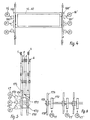
- eine schematische Darstellung eines direkten Schaftantriebes über eine Zahnstangen-Zahnrad-Kombination mit zwei Motoren pro Schaft,
- Fig. 5 und 6
- zwei Ansichten einer schematischen Darstellung eines paarweisen Schaftantriebes mit Hilfe von Zahnstangen,
- Fig.7
- eine Antriebsanordnung für den Antriebshebel mittels Schneckengetriebe und
- Fig. 8 .... 14
- unterschiedliche Bindungsvarianten der Bindekette für Doppelteppichgewebe - links als schematische Schnittdarstellung einer Oberware und rechts als Bewegungsdiagramm der Schäfte für die Bindekettfäden.
Die Schäfte S (hier in ihrer Gesamtheit bezeichnet) dieser Webmaschine besitzen in Abhängigkeit von der Arbeitsbreite eine große Länge. Dadurch ist es notwendig, die Antriebsbewegung an mehreren Abschnitten auf den Rahmen derselben zu übertragen.
Die Schäfte S der Webmaschine dienen hier dazu, die nicht mustergemäß ausgewählten Fäden der Bindekette BO, BU und der Füllkette FO, FU im Zusammenhang mit dem Schußeintrag zur Herstellung der jeweiligen Grundware zu führen. Die Schäfte werden in ihrer Gesamtheit mit S bezeichnet. Für die Beschreibung der Arbeitsweise einzelner Schäfte werden die Ziffern 1 bis 6 gebraucht.
An der Fachbildung einer Doppelteppichwebmaschine sind außerdem die durch eine Jacquardvorrichtung ansteuerbaren Polfadenführer beteiligt.
In die durch die genannten Fachsteuerungselemente S, JL gebildeten Fächer werden die Greiferstangen GO, GU geführt, die in jeder Tour oder in ausgewählten Touren je einen Schußfaden SO, SU einführen.
Die Steuerung der Schäfte S zum Zweck der Fachbildung soll zunächst anhand der Fig. 1, bezogen auf den Schaft 1, in einem ersten Ausführungsbeispiel beschrieben werden.
Im vorliegenden Beispiel sind jedem Schaftrahmen, oder einfach gesagt, jedem Schaft 1....6 drei Winkelhebel 122 zugeordnet, die über je eine Koppel 121 die Schäfte 1....6 in vertikaler Richtung antreiben. Die Winkelhebel 122 sind durch eine Antriebsschiene 123 pro Schaft 1, die sich über einen großen Teil der Maschine erstreckt, miteinander formschlüssig antriebsverbunden.
Diese Antriebsschiene 123 wird vorzugsweise außerhalb des Arbeitsbereiches der Webmaschine über einen ihr zugeordneten Antriebshebel 124 angetrieben. Dieser ist seinerseits über eine Koppel 125 mit der Mutter 131 eines Kugelspindelantriebes 13 verbunden. Die Kugelgewindespindel 132 ist direkt oder über eine Kupplung mit der Achse des Motors 14 gekoppelt.
Jedem Antriebhebel 124, der einem Schaft 1...6 zugeordnet ist, ist ein solches Kugelpindelgetriebe 13 zugeordnet. Jede Kugelgewindespindel 132 wird jeweils über einen separaten positionsorientiert steuerbaren Motor 141, 142, 143, 144, 145, 146 angetrieben.
Für die positionsorientierte Steuerung dieser Motoren ist ihnen je ein IGR (Inkrementaler Geber) an der Motorwelle und eine separate Steuereinheit 151, 152, 153, 154, 155, 156 zugeordnet.
Ein zentraler Steuerrechner 8 koordiniert die separaten Steuereinheiten 151, 152, 153, 154, 155, 156. Dieser Steuerrechner besitzt Eingänge zum Empfang von Synchronisationssignalen des Gebers 81 an der Hauptwelle HW der Maschine. Zusätzlich hat der Steuerrechner Eingänge, die mit dem Schußwächter SW verbunden sind und Eingänge, die Informationen bzw. Impulse der Kettwächter KW1 .... KW4 übernehmen. Diese Kettwächter sind den Kettfäden entsprechend ihrer Funktion ( vorzugsweise schaftweise) gruppenweise zugeordnet. Diese Zuordnung dient vor allem dem Zweck, daß das jeweilige Kettfadensystem, in dem ein Kettfadenbruch festgestellt wurde, beim Stillsetzen der Maschine die Fachbilgung in einer solchen Position zu beenden, die eine optimale Bedienung bei der Behebung des Kettfadenbruches gewährleistet.
Die linke Darstellung zeigt dabei jeweils einen schematischen Querschnitt durch Oberware des Doppelteppichgewebes längs der Kettfäden.
Die rechte Darstellung zeigt dazu die/das Bewegungsdiagramm/e des jeweiligen Schaftes 1 .... 4 der entsprechenden Bindekette BO, BU.
Der Abstand zwischen je zwei einander benachbarten senkrechten Linien deutet den Abstand zwischen zwei Fachvertritten in zwei aufeinander folgenden Touren an. Die oberste Linie symbolisiert das Oberfach O, die mittelste das Mittelfach M und die unterste Linie das Unterfach U.
Vorrangig wird hier jeweils der Bindekettfaden BO der Oberware verfolgt.
Die in Fig. 11 gezeigte Bindung wird als Rips-2/2 (4-tourig) bezeichnet. Man verwendet sie bei der sog. AT-Bindung, bei der im Wechsel jeweils 2 Schüsse in einer ersten Tour in die Oberware und danach 2 Schüsse in einer zweiten Tour in die Unterware eingetragen werden.
Damit der Gesamthub der Polkettfäden P, der diesen über die Jacquardlitzen JL erteilt werden muß, relativ niedrig gehalten werden kann, erfolgt die Führung dieser Polfäden P für die Fachbildung in möglichst geringem Abstand hinter der Schußeintragsebene, d.h. unmittelbar hinter dem Webblatt 91, wenn sich dasselbe in seiner hinteren Position befindet.
Hier geht es einerseits darum, diese Fäden im Abstand voneinander aber möglichst sehr nahe nebeneinander zu führen. Bei der Sicherung einer derartigen Anforderung geht es dann darum, daß jeder Schaft 1 .... 6 entsprechend seiner Lage und in Abhängigkeit von der jeweiligen Bindung unterschiedliche Hubgrößen und unterschiedlilche Lagen des Hubes realisieren muß.
Bei normalem Betrieb der Schaftbewegung im herkömmlichen Sinne erreichen nahezu beide Bindekettfäden BO1, BO2; BU1, BU2 und auch die Füllkette FO, FU der Ober- oder Unterware jeweils gleichzeitig ihre Mittelstellung im oberen bzw. im unteren Fach.
Dabei klemmen sie meist die zwischen ihnen geführten Polkettfäden P, die einen sehr großen Hub ausführen müssen, zwischen sich ein und stören damit deren Fachbildung.
Das kann einmal dazu führen, daß sich abstehende Fasem der Polkettfäden P um Bindekettfäden BO, BU oder Füllketten FO, FU schlingen und dann an diesen Fäden fest haften (klammern).
In einem anderen Fall können die geklemmten Polfäden P, bedingt durch diese Klammerung um einen größeren Betrag in das Fach gezogen werden.
Sie werden dann bei der nächsten Fachbildung locker und ein fehlerfreier Schußeitrag ist nicht mehr in jedem Fall gesichert.
Dadurch, daß jeder einzelne Motor 141, 142, 143, 144, 145, 146 jeweils einen Schaft 1, 2, 3, 4, 5, 6 antreibt, kann dessen Hubgröße, die Lage des Hubes und der Mittendurchgang beim Fachwechsel durch ein Programm in ganz spezifischer Weise vorgegeben werden.
Dieses Programm kann entweder durch die Eingabe geänderter Programmspeicher oder durch das programmgemäße Ansteuern und Abrufen interner Speicher verändert werden.
Wird die Maschine aufgrund eines Schußfadenbruches, ausgelöst durch den Schußwächter SW, stillgesetzt, so kann die Maschine mit ihren Arbeitselementen - insbesondere zur Fachbildung - unabhängig von den übrigen Antrieben in eine solche Position gebracht werden, wo der gebrochene Schußfaden entfernt und durch einen neuen Schußfaden ersetzt werden kann.
Wird durch einen Kettfadenwächter KW1, KW2, KW3, KW4 für gruppenweise zugeordnete Fadensysteme ein Kettfadenbruch angezeigt, dann kann ein so selektiertes Fadenbruchsignal jeweils die Gruppe der Kettfäden BO1, BO2, BU1, BU2, FO, FU, in der ein Faden gerissen ist, in eine optimal bedienbare Position bringen. Trifft das z. B. auf die obere Bindekette BO1 zu, dann wird deren Schaft 1 in die optimale Bedienposition bewegt, während die übrigen Schäfte eine Position einnehmen, in der die Kettfäden nicht übermäßig belastet werden.
Insbesondere für den letztgeschilderten Fall ist es sinnvoll, auch die Fachbildung der jacquardgesteuerten Polfäden P gruppenweise und unabhängig voneinander steuerbar zu gestalten.
Im vorliegenden Beispiel treiben sie über ein Zahngetriebe 713, 723 eine der Schwingwellen 711, 721 und das jeweilige Koppelgetriebe 712, 722. Für die Gestaltung der Bewegungsprogramme für diese Motoren 714, 724 kommt es darauf an, die zur Musterung ausgewählten Polfäden P während längerer Stillstandsphasen in eine solche Position zu bewegen, in der ein Überspannen der Polfäden vermieden wird.
So ist es nach einer Ausführung gemäß Fig. 4 möglich, die Schäfte 1 ... 6 an ihren Seiten mit Zahnstangen 162 zu koppeln, die gemeinsam mit den Schäften vertikal beweglich sind.
An jeder Seite des Schaftes kann ein Motor 16, 16' mit einem Ritzel 161 in diese Zahnstangen 162 eingreifen und die Schäfte 1 ... 6 in beliebiger Weise heben und senken.
Bei einer derartigen Ausführung ist es jedoch notwendig, für jeden Schaft 1(...6) zwei Motoren 16, 16' anzuordnen. Diese Motoren 16, 16' können jedoch in einer kleineren Größe gewählt werden, da die Zahl der bewegten Elemente und deren Masse deutlich verringert ist. Positive Wirkungen kommen auch dadurch zustande, daß beide Motoren 16, 16', die gemeinsam je einen Schaft 1 ...6 steuern, durch eine gemeinsame Steuervorrichtung angesteuert werden können. Der Vorrichtungsaufwand bleibt dadurch in Grenzen.
Die Schäfte 5, 6 der Füllketten FO, FU können. bei vielen Bindungen parallel zueinander gesteuert werden. Es ist auch möglich, hier beide Schäfte 5, 6 starr miteinander zu koppeln und beide Schäfte 5, 6 durch einen einzigen Motor 17" zu treiben.
Zur Korrektur des Mittendurchganges reicht es oft aus, die Bewegung der Bindekette BO, BU einer Ware im Verhältnis zur Füllkette FO, FU zu verändern.
Anstelle des Kugelspindelgetriebes 13 oder des Zahnstangengetriebes nach den Fig. 4 oder Fig. 5 und 6 kann man auch ein Untersetzungsgetriebe 713 oder 714 gemäß Fig 3 verwenden. Die Drehbewegung des Motors 714, 724 wird hier mittels Zahnriemengetriebe 713, 723 auf die Schwingwelle 711, bzw. 721 übertragen und von dort mittels zweier, zueinander paralleler Koppelgetriebe 712, 712'; 722, 722' auf den Messerkasten 71 bzw. auf den Träger 72 für die Fingerrechen übertragen. Eine einfache, für kleinere Webmaschinen geeignete Antriebsform zeigt Fig. 7. Hier besitzt der Antriebshebel 124' ein Zahnsegment, des mit einer Schnecke zusammenwirkt, die direkt von dem Motor 14 getrieben wird.
Für die Realisierung eines solchen Konzeptes ist es geboten, alle Motoren auch als Generator zu nutzen und die so gewonnene Energie in einem Zwischenstromkreis zeitweilig zwischenzuspeichern und wieder für den Antrieb bereit zu halten. Hierfür hält der Stand der Technik ansprechende Lösungen bereit. Auf das "Wie" braucht deshalb an dieser Stelle nicht im einzelnen eingegangen werden.
- 1, 2, 3, 4, 5, 6
- Schaft
- 11
- Litzen
- 12
- Koppelgetriebe
- 121
- Koppel
- 122
- Winkelhebel
- 123
- Antriebsschwinge
- 124, 124'
- Antriebshebel
- 125
- Koppel
- 13
- Kugelspindelgetriebe
- 131
- Mutter
- 132
- Kugelspindel
- 133
- Schnecke
- 14
- Motor
- 141 .... 146
- Motor
- 151 .... 156
- Steuereinheit
- 16, 16'
- Motor
- 161
- Ritzel
- 162
- Zahnstange
- 17, 17', 17"
- Motor
- 170
- Zahnrad
- 171
- Zahnrad
- 172
- Zahnriemen
- 173
- Zahnrad (Abtriebsrad)
- 174, 175
- Zahnstange
- (7)
- Jacquardmaschine
- 71
- Messerkasten
- 711
- Schwingwelle
- 712, 712'
- Koppelgetriebe
- 713
- Zahnriemengetriebe
- 714
- Motor
- 72
- Träger für Fingerrechen
- 721
- Schwingwelle
- 722, 722'
- Koppelgetriebe
- 723
- Zahnradgetriebe
- 724
- Motor
- 8
- Steuerrechner
- 81
- Geber
- 82
- Bedieneinheit
- 91
- Webblatt
- BO
- Bindekette oben
- BO1, BO2
- Bindekette oben, 2fädig
- BO3
- Bindekette oben, 1fädig
- BU
- Bindekette unten
- BU1, BU2
- Bindekette unten, 2fädig
- BU3
- Bindekette unten, 1fädig
- FO
- Füllkette oben
- FU
- Füllkette unten
- P
- Polfäden
- SO, SU
- Schußfäden
- S(1 .... 6)
- Schäfte/Schaftanordnung
- JL
- Jacquardlitzen
- GO
- Greiferstange oben
- GU
- Greiferstange unten
- SW
- Schußwächter
- KW1 .... KW4
- Kettwächter
- HW
- Hauptwelle
- O
- Oberfach
- 01
- Zone
- M
- Mittelfach
- M1
- Zone
- U
- Unterfach
- U1
- Zone
- ->
- Mittendurchgang /Nulldurchgang
Claims (13)
- Antriebsvorrichtung für die Fachbildeelemente von Webmaschinen, insbesondere Doppelflorwebmaschinenwobei jedem Fachbildeelement (Schäfte bzw. Messerkasten), zum Zwecke ihres Antriebes in Hubrichtung, ein steuerbarer Motor zugeordnet ist,die, ausgebildet als Schäfte, Messerkästen oder dgl., in Abhängigkeit vom Webrythmus eine Hubbewegung in wechselnden Richtungen relativ zur Schußeintragsebene ausführen,an denen die die Kettfäden führenden Litzen ständig oder zeitweilig, mustergemäß wechselnd, direkt oder über Zwischenglieder angekoppelt sind,
wobei die Antriebsbewegung der Motoren auf das jeweilige Fachbildeelement (Schäfte bzw. Messerkasten) übertragen wird und
wobei dem Steuerrechner Programmspeicher für die Ansteuerung der Fachbildeelemente zugeordnet sind, dadurch gekennzeichnet, dass die Servomotoren positionsorientiert umsteuerbare Servomotoren (14, 141, 142, 143, 144, 145, 146) mit inkrementalen Gebern sind,
dass zwischen dem jeweiligen Servomotor und einem zugeordneten Antriebshebel (z. B. 124) eines an sich bekannten, Koppelgetriebes jeweils ein Untersetzungsgetriebe (Kugelspindelgetriebe 13, Schneckengetriebe 133 oder Zahnriemengetriebe 713, 723) angeordnet ist,
dass das Koppelgetriebe (12; 712, 712'; 722, 722') mit mindestens zwei synchron zueinander bewegbaren, in sich starren Abtriebsgliedern (z.B. 121) zum Schaft (1) bzw. zum Messerkasten (71; 72) ausgestattet ist, und
dass dem Steuerrechner (8) Programmspeicherfür wählbare Programmkomplexe zur Steuerung der Fachbildeelemente nach unterschiedlichen Bewegungsgestzen für mehrere Grundbindungen zugeordnet sind. - Antriebsvorrichtung nach Anspruch 1, dadurch gekennzeichnet, dass die Servomotoren (14, 141, 142, 143, 144, 145, 146) jeweils mit ihrem Untersetzungsgetriebe (13) seitlich der Schaftanordnung (S) und seitlich zueinander versetzt und / oder übereinander angeordnet sind.
- Antriebsvorrichtung nach Anspruch 1, dadurch gekennzeichnet, dass das Untersetzungsgetriebe ein Kugelspindelgetriebe (13) ist, dessen Kugelspindel (132) mit der Antriebswelle des Motors (141, 142, 143, 144, 145, 146) gekoppelt ist und dessen Abtriebsglied (131) mit dem Antriebshebel (124) des Koppelgetriebes (12) verbunden ist.
- Antriebsvorrichtung nach Anspruch 1, dadurch gekennzeichnet, dass das Untersetzungsgetriebe ein Schneckenget riebe ist, dessen Schnecke (133) vom Motor (14) getrieben und dessen Schneckenrad mit der Antriebsschwinge (124') des Koppelgetriebes (12) verbunden ist.
- Antriebsvorrichtung nach Anspruch 1, dadurch gekennzeichnet, dass das Untersetzungsgetriebe ein Zahnriemengetriebe (713, 723) ist, dessen Antriebsrad auf der Motorwelle und dessen Abtriebsrad auf der Antriebsschwinge (711, 721) des Koppelgetriebes (12, 712, 722) angeordnet ist.
- Antriebsvorrichtung nach Anspruch 1, dadurch gekennzelchnet,
dass jedem Messerkasten (71) der Jacquardmaschine für den Hubantrieb je ein umsteuerbarer Servomotor (714,724) und zwei zueinander parallele Koppelgetriebe (712, 712'; 722, 722') zugeordnet ist. - Antriebsvorrichtung nach Anspruch 1, dadurch gekennzeichnet, dass die Servomotoren (14; 141, 142, 143, 144, 145, 146; 16,16'; 17, 17', 17") auf Tacho-Generator-Betrieb umschaltbar sind und dass den Servomotoren (14; 141, 142, 143, 144, 145, 146; 16, 16'; 17, 17', 17") ein gemeinsamer Zwischenstromkreis zugeordnet ist, der mit Stromspeichem versehen ist.
- Antriebsvorrichtung nach Anspruch 1, dadurch gekennzeichnet, dass den Programmspeichern der Steuerrechner (8) auch Programme für die Korrektur des Nulldurchganges der Kettfäden und für die Veränderung der Endlagen des jeweiligen Schafthubes zugeordnet sind.
- Antriebsvorrichtung nach einem der Ansprüche 1 oder 10,
dadurch gekennzeichnet, dass dem Steuerrechner (8) wählbare Programm komplexe für materialabhängige Varianten jeder Grundbindung zugeordnet sind. - Antriebsvorrichtung nach Anspruch 1, dadurch gekennzeichnet, dass dem Steuerrechner (8) Programmspeicher für die Positionssteuerung der Fachbildeelemente bei Kettbruch, bei Schußbruch, beim Abstellen der Maschine über längere Zeitabschnitte und beim Wiederanfahren aus unterschiedlichen Haltepositionen der Maschine zugeordnet sind.
- Antriebsvorrichtung nach Anspruch 1 und 10,
dadurch gekennzeichnet, dass dem Steuerrechner (8) ein Anhalteprogramm zugeordnet ist,das durch den Impuls eines Schußwächters (SW) aktivierbar ist,das einen Speicher für die Schaftposition beim Schußbruch ent hält undein Antriebsprogramm umfaßt, das die Servomotoren bis zur Schaftposition beim Schußbruch führt. - Antriebsvorrichtung nach Anspruch 1 und 11,
dadurch gekennzeichnet, dass dem Steuerrechner (8) mindestens zwei Anhalteprogramme zugeordnet sind, die jeweils durch den Impuls eines Kettfadenwächters (KW1, KW2, KW3, KW4) einer Kettfadengruppe (BO1, B02; BU1, BU2, FO, FU) aktivierbar sind, und
dass jedes der Anhalteprogramme die Schäfte (1... 6) vorübergehend in eine Position führt, in der die jeweilige Kettfadengruppe optimal bedienbar ist. - Antriebsvorrichtung nach Anspruch 1, 11 oder 12,
dadurch gekennzeichnet, dass dem Steuerrechner (8) ein weiteres Anhalteprogramm zugeordnet ist, das durch einen Taster aktivierbar ist und das Steuerbefehle für das Positionieren der Fachbildeelemente (S,JL) in einer Position zwischen den Endlagen enthält.
Applications Claiming Priority (2)
| Application Number | Priority Date | Filing Date | Title |
|---|---|---|---|
| DE19651799A DE19651799A1 (de) | 1996-12-13 | 1996-12-13 | Antriebsvorrichtung für die Fachbildeelemente von Webmaschinen |
| DE19651799 | 1996-12-13 |
Publications (2)
| Publication Number | Publication Date |
|---|---|
| EP0848097A1 EP0848097A1 (de) | 1998-06-17 |
| EP0848097B1 true EP0848097B1 (de) | 2003-04-02 |
Family
ID=7814542
Family Applications (1)
| Application Number | Title | Priority Date | Filing Date |
|---|---|---|---|
| EP97120405A Revoked EP0848097B1 (de) | 1996-12-13 | 1997-11-21 | Antriebsvorrichtung für die Fachbildeelemente von Webmaschinen |
Country Status (2)
| Country | Link |
|---|---|
| EP (1) | EP0848097B1 (de) |
| DE (2) | DE19651799A1 (de) |
Families Citing this family (10)
| Publication number | Priority date | Publication date | Assignee | Title |
|---|---|---|---|---|
| DE10111017B4 (de) * | 2001-03-07 | 2006-02-02 | Lindauer Dornier Gmbh | Antrieb für die Webschäfte einer Webmaschine |
| EP1260620A1 (de) * | 2001-05-21 | 2002-11-27 | Officina Meccanica Trinca Colonel Silvio & Figlio Sergio S.n.c. | Vorrichtung zum automatischen bewegen und einstellen von Webschäften in Webmaschinen |
| FR2826671B1 (fr) * | 2001-06-29 | 2003-09-12 | Staubli Lyon | Dispositif de formation de la foule sur un metier a tisser de type jacquard |
| FR2856412B1 (fr) * | 2003-06-19 | 2005-07-22 | Staubli Sa Ets | Dispositif de formation de la foule pour metier a tisser equipe de cadres de lisses, et metier a tisser incorporant un tel dispositif |
| DE502004004436D1 (de) * | 2004-06-18 | 2007-09-06 | Schoenherr Textilmaschinenbau | Verfahren und Vorrichtung zur Fachbildung jacquardgemusterter Polkettfäden auf einer Doppelflorwebmaschine |
| BE1016427A5 (nl) | 2005-01-25 | 2006-10-03 | Wiele Michel Van De Nv | Inrichting voor het aansturen van bind-en spankettinggarens, en poolweefmachine voorzien van een dergelijke inrichting. |
| DE502007002798D1 (de) * | 2006-08-29 | 2010-03-25 | Schneider & Ozga | Breitwebmaschine |
| DE102006040475A1 (de) * | 2006-08-29 | 2008-03-20 | Schneider & Ozga | Breitwebmaschine |
| DE202015105812U1 (de) * | 2015-11-02 | 2017-01-30 | GITEC Grosse Internationale Technologie GmbH | Fachbildevorrichtung |
| CN109234897A (zh) * | 2018-09-12 | 2019-01-18 | 刘道灵 | 一种用于纺布的智能制造装置 |
Family Cites Families (10)
| Publication number | Priority date | Publication date | Assignee | Title |
|---|---|---|---|---|
| SE444007B (sv) * | 1981-07-15 | 1986-03-17 | Aelmhults Bruk Ab | Hydraulisk skelbildningsanordning |
| DE3721932A1 (de) * | 1987-07-02 | 1989-01-19 | Grosse Webereimaschinen Gmbh | Doppelhub-offenfach-jacquardmaschine |
| DE8710997U1 (de) * | 1987-08-12 | 1987-11-26 | Emil Jäger GmbH & Co KG, 4400 Münster | Webmaschine mit einer mechanischen Schaftmaschine |
| DD301487A7 (de) * | 1989-03-29 | 1993-02-11 | Chemnitzer Webmasch Gmbh | Antriebsvorrichtung fuer webmaschinen, insbesondere doppelteppich- und plueschwebmaschinen |
| FR2660672B1 (fr) * | 1990-04-06 | 1992-08-28 | Staubli Sa Ets | Systeme pour l'entrainement d'une machine pour la formation de la foule sur une machine a tisser. |
| JP2892482B2 (ja) * | 1990-10-15 | 1999-05-17 | 津田駒工業株式会社 | 織機の経糸開口制御装置 |
| JP2877522B2 (ja) * | 1990-12-28 | 1999-03-31 | 津田駒工業株式会社 | 織機の綜絖枠駆動回路 |
| FR2724948B1 (fr) * | 1994-09-27 | 1996-12-27 | Staubli Sa Ets | Mecanisme jacquard du type a courroies |
| SE510772C2 (sv) * | 1995-06-12 | 1999-06-21 | Texo Ab | Anordning vid vävmaskin för anpassning av underskälets varp till resulterande kraftskillnader i under- och överskäl |
| DE29618645U1 (de) * | 1996-10-25 | 1997-01-02 | Schneider & Ozga, 95463 Bindlach | Schaftmaschine |
-
1996
- 1996-12-13 DE DE19651799A patent/DE19651799A1/de not_active Withdrawn
-
1997
- 1997-11-21 DE DE59709686T patent/DE59709686D1/de not_active Revoked
- 1997-11-21 EP EP97120405A patent/EP0848097B1/de not_active Revoked
Also Published As
| Publication number | Publication date |
|---|---|
| DE19651799A1 (de) | 1998-06-18 |
| EP0848097A1 (de) | 1998-06-17 |
| DE59709686D1 (de) | 2003-05-08 |
Similar Documents
| Publication | Publication Date | Title |
|---|---|---|
| DE3788697T2 (de) | Tetraaxialgewebe und Webstuhl zum Herstellen von Tetraaxialgewebe. | |
| EP2580379B1 (de) | Webmaschine zur herstellung von webgut mit einem eingearbeiteten legefaden | |
| EP0565122B1 (de) | Verfahren zum doppelspuligen Weben eines Doppelstückgewebes mit Zweischussbindung und Doppelstück-Webmaschine mit vertikal bewegbaren Schusseinführ-Vorrichtungen zur Durchführung des Verfahrens | |
| DE102012200835B3 (de) | Webmaschine mit einer Vorrichtung zur Bildung von Zusatzschusseffekten | |
| EP0627511B1 (de) | Jacquardmaschine | |
| DE1963208B2 (de) | Wellenwebmaschine | |
| EP0848097A1 (de) | Antriebsvorrichtung für die Fachbildeelemente von Webmaschinen | |
| DE2616910A1 (de) | Vorrichtung zur bildung einer dreherbindungs-webkante auf webstuehlen | |
| EP1564320B1 (de) | Fachbildeeinrichung für eine Webmaschine | |
| DE19615671A1 (de) | Vorrichtung zur Herstellung von Kettenwirkware mit zwei voneinander unabhängigen Wirkbereichen | |
| DE1966664A1 (de) | Vorrichtung zur gesteuerten fachbildung bei wellenfachwebmaschinen | |
| DE60116289T2 (de) | Weben von teppichen | |
| DE69017256T2 (de) | Fachbildungsvorrichtung für eine Rundwebmaschine. | |
| EP1607501B1 (de) | Verfahren und Vorrichtung zur Fachbildung jacquardgemusterter Polkettfäden auf einer Doppelflorwebmaschine | |
| DE60005605T2 (de) | Polfadenauswahlsystem für Axminster Greiferwebmaschinen | |
| EP0879308B1 (de) | Kantenbildungsvorrichtung für eine webmaschine | |
| WO2012163571A2 (de) | Schaftwebmaschine und entsprechendes webverfahren | |
| DE19623173B4 (de) | Webmaschinenanordnung | |
| DE2164948A1 (de) | Verfahren zum weben von doppel-florgeweben | |
| DE3874738T2 (de) | Webmaschine mit vertikal bewegbarem schusseintragelement fuer die fabrikation von doppelplueschgeweben, teppichen und dergleichen mit sehr langem flor. | |
| CH671591A5 (de) | ||
| DE60116089T2 (de) | Einheit zum Bilden von Tuftinggarnen und Webmaschine | |
| DE3810335A1 (de) | Luftduesenwebmaschine mit schussfadenklemm- und streckeinrichtung | |
| DE60021313T2 (de) | Kantenfachbildungsvorrichtung sowie Webmaschine mit einer solchen Vorrichtung | |
| DE1535768B1 (de) | Webstuhl zum Herstellen von Kettenflorgeweben |
Legal Events
| Date | Code | Title | Description |
|---|---|---|---|
| PUAI | Public reference made under article 153(3) epc to a published international application that has entered the european phase |
Free format text: ORIGINAL CODE: 0009012 |
|
| AK | Designated contracting states |
Kind code of ref document: A1 Designated state(s): BE CH DE FR GB IT LI |
|
| AX | Request for extension of the european patent |
Free format text: AL;LT;LV;MK;RO;SI |
|
| 17P | Request for examination filed |
Effective date: 19980727 |
|
| AKX | Designation fees paid |
Free format text: BE CH DE FR GB IT LI |
|
| RBV | Designated contracting states (corrected) |
Designated state(s): BE CH DE FR GB IT LI |
|
| 17Q | First examination report despatched |
Effective date: 20001009 |
|
| GRAG | Despatch of communication of intention to grant |
Free format text: ORIGINAL CODE: EPIDOS AGRA |
|
| GRAG | Despatch of communication of intention to grant |
Free format text: ORIGINAL CODE: EPIDOS AGRA |
|
| GRAH | Despatch of communication of intention to grant a patent |
Free format text: ORIGINAL CODE: EPIDOS IGRA |
|
| RIN1 | Information on inventor provided before grant (corrected) |
Inventor name: KAISER, STEFFEN Inventor name: HETZER, HANS-DIETER Inventor name: GOESSL, RAINER, DR. |
|
| RAP1 | Party data changed (applicant data changed or rights of an application transferred) |
Owner name: SCHOENHERR TEXTILMASCHINENBAU GMBH |
|
| GRAH | Despatch of communication of intention to grant a patent |
Free format text: ORIGINAL CODE: EPIDOS IGRA |
|
| GRAA | (expected) grant |
Free format text: ORIGINAL CODE: 0009210 |
|
| AK | Designated contracting states |
Designated state(s): BE CH DE FR GB IT LI |
|
| REG | Reference to a national code |
Ref country code: GB Ref legal event code: FG4D Free format text: NOT ENGLISH |
|
| REG | Reference to a national code |
Ref country code: CH Ref legal event code: EP |
|
| REF | Corresponds to: |
Ref document number: 59709686 Country of ref document: DE Date of ref document: 20030508 Kind code of ref document: P |
|
| GBT | Gb: translation of ep patent filed (gb section 77(6)(a)/1977) | ||
| ET | Fr: translation filed | ||
| PG25 | Lapsed in a contracting state [announced via postgrant information from national office to epo] |
Ref country code: GB Free format text: LAPSE BECAUSE OF NON-PAYMENT OF DUE FEES Effective date: 20031121 |
|
| PLBQ | Unpublished change to opponent data |
Free format text: ORIGINAL CODE: EPIDOS OPPO |
|
| PLBI | Opposition filed |
Free format text: ORIGINAL CODE: 0009260 |
|
| PG25 | Lapsed in a contracting state [announced via postgrant information from national office to epo] |
Ref country code: LI Free format text: LAPSE BECAUSE OF NON-PAYMENT OF DUE FEES Effective date: 20031130 Ref country code: CH Free format text: LAPSE BECAUSE OF NON-PAYMENT OF DUE FEES Effective date: 20031130 |
|
| 26 | Opposition filed |
Opponent name: N.V. MICHEL VAN DE WIELE Effective date: 20031114 |
|
| PLAX | Notice of opposition and request to file observation + time limit sent |
Free format text: ORIGINAL CODE: EPIDOSNOBS2 |
|
| PLBB | Reply of patent proprietor to notice(s) of opposition received |
Free format text: ORIGINAL CODE: EPIDOSNOBS3 |
|
| GBPC | Gb: european patent ceased through non-payment of renewal fee |
Effective date: 20031121 |
|
| REG | Reference to a national code |
Ref country code: CH Ref legal event code: PL |
|
| PGFP | Annual fee paid to national office [announced via postgrant information from national office to epo] |
Ref country code: FR Payment date: 20041028 Year of fee payment: 8 |
|
| PGFP | Annual fee paid to national office [announced via postgrant information from national office to epo] |
Ref country code: DE Payment date: 20041109 Year of fee payment: 8 |
|
| PGFP | Annual fee paid to national office [announced via postgrant information from national office to epo] |
Ref country code: BE Payment date: 20041208 Year of fee payment: 8 |
|
| RDAF | Communication despatched that patent is revoked |
Free format text: ORIGINAL CODE: EPIDOSNREV1 |
|
| RDAG | Patent revoked |
Free format text: ORIGINAL CODE: 0009271 |
|
| STAA | Information on the status of an ep patent application or granted ep patent |
Free format text: STATUS: PATENT REVOKED |
|
| 27W | Patent revoked |
Effective date: 20050913 |