EP0847661B2 - Akustisches gerät - Google Patents
Akustisches gerät Download PDFInfo
- Publication number
- EP0847661B2 EP0847661B2 EP96929390A EP96929390A EP0847661B2 EP 0847661 B2 EP0847661 B2 EP 0847661B2 EP 96929390 A EP96929390 A EP 96929390A EP 96929390 A EP96929390 A EP 96929390A EP 0847661 B2 EP0847661 B2 EP 0847661B2
- Authority
- EP
- European Patent Office
- Prior art keywords
- acoustic device
- panel
- acoustic
- transducer
- radiator
- Prior art date
- Legal status (The legal status is an assumption and is not a legal conclusion. Google has not performed a legal analysis and makes no representation as to the accuracy of the status listed.)
- Expired - Lifetime
Links
- 238000005452 bending Methods 0.000 claims abstract description 216
- 230000009471 action Effects 0.000 claims abstract description 59
- 238000000034 method Methods 0.000 claims abstract description 44
- 238000009826 distribution Methods 0.000 claims abstract description 41
- 230000001419 dependent effect Effects 0.000 claims abstract description 12
- 239000000463 material Substances 0.000 claims description 64
- 239000000725 suspension Substances 0.000 claims description 62
- 230000000694 effects Effects 0.000 claims description 39
- 238000013016 damping Methods 0.000 claims description 36
- 239000004033 plastic Substances 0.000 claims description 35
- 229920003023 plastic Polymers 0.000 claims description 35
- 230000001413 cellular effect Effects 0.000 claims description 31
- 238000004458 analytical method Methods 0.000 claims description 26
- 230000033001 locomotion Effects 0.000 claims description 23
- 230000000007 visual effect Effects 0.000 claims description 23
- 230000009286 beneficial effect Effects 0.000 claims description 21
- 239000002131 composite material Substances 0.000 claims description 21
- 230000004044 response Effects 0.000 claims description 21
- 239000000853 adhesive Substances 0.000 claims description 19
- 230000001070 adhesive effect Effects 0.000 claims description 18
- 230000008878 coupling Effects 0.000 claims description 18
- 238000010168 coupling process Methods 0.000 claims description 18
- 238000005859 coupling reaction Methods 0.000 claims description 18
- 230000000295 complement effect Effects 0.000 claims description 17
- 230000000712 assembly Effects 0.000 claims description 16
- 238000000429 assembly Methods 0.000 claims description 16
- 238000004806 packaging method and process Methods 0.000 claims description 15
- 239000000123 paper Substances 0.000 claims description 15
- 230000008093 supporting effect Effects 0.000 claims description 11
- 238000004519 manufacturing process Methods 0.000 claims description 9
- 230000000670 limiting effect Effects 0.000 claims description 7
- 239000005030 aluminium foil Substances 0.000 claims description 6
- 238000010276 construction Methods 0.000 claims description 6
- 239000002655 kraft paper Substances 0.000 claims description 6
- 230000005291 magnetic effect Effects 0.000 claims description 6
- 230000007246 mechanism Effects 0.000 claims description 6
- 239000013536 elastomeric material Substances 0.000 claims description 5
- 230000002829 reductive effect Effects 0.000 claims description 5
- 125000006850 spacer group Chemical group 0.000 claims description 5
- 238000003860 storage Methods 0.000 claims description 5
- 229920002430 Fibre-reinforced plastic Polymers 0.000 claims description 4
- 230000002411 adverse Effects 0.000 claims description 3
- 238000007906 compression Methods 0.000 claims description 3
- 230000006835 compression Effects 0.000 claims description 3
- 239000011151 fibre-reinforced plastic Substances 0.000 claims description 3
- 230000002745 absorbent Effects 0.000 claims description 2
- 239000002250 absorbent Substances 0.000 claims description 2
- 238000011084 recovery Methods 0.000 claims description 2
- 230000000875 corresponding effect Effects 0.000 claims 23
- 230000002596 correlated effect Effects 0.000 claims 4
- 238000013461 design Methods 0.000 abstract description 18
- 239000011162 core material Substances 0.000 description 85
- 239000010410 layer Substances 0.000 description 18
- 230000036961 partial effect Effects 0.000 description 15
- 241000264877 Hippospongia communis Species 0.000 description 12
- 230000008901 benefit Effects 0.000 description 12
- 229910052751 metal Inorganic materials 0.000 description 12
- 239000002184 metal Substances 0.000 description 12
- 230000001976 improved effect Effects 0.000 description 10
- 229920001821 foam rubber Polymers 0.000 description 9
- 239000006260 foam Substances 0.000 description 8
- 238000009432 framing Methods 0.000 description 8
- 238000010586 diagram Methods 0.000 description 7
- 239000011888 foil Substances 0.000 description 7
- OKTJSMMVPCPJKN-UHFFFAOYSA-N Carbon Chemical compound [C] OKTJSMMVPCPJKN-UHFFFAOYSA-N 0.000 description 6
- 229910052799 carbon Inorganic materials 0.000 description 6
- 238000005516 engineering process Methods 0.000 description 6
- 230000005284 excitation Effects 0.000 description 6
- 230000005855 radiation Effects 0.000 description 6
- 238000003462 Bender reaction Methods 0.000 description 5
- 238000013459 approach Methods 0.000 description 5
- 230000005520 electrodynamics Effects 0.000 description 5
- 230000001965 increasing effect Effects 0.000 description 5
- 230000004807 localization Effects 0.000 description 5
- 230000008447 perception Effects 0.000 description 5
- 230000002093 peripheral effect Effects 0.000 description 5
- 238000012545 processing Methods 0.000 description 5
- 238000012216 screening Methods 0.000 description 5
- 238000004904 shortening Methods 0.000 description 5
- 229910000838 Al alloy Inorganic materials 0.000 description 4
- 238000004364 calculation method Methods 0.000 description 4
- 239000003990 capacitor Substances 0.000 description 4
- 238000005520 cutting process Methods 0.000 description 4
- 239000006185 dispersion Substances 0.000 description 4
- 229920001971 elastomer Polymers 0.000 description 4
- 229920006332 epoxy adhesive Polymers 0.000 description 4
- 230000002452 interceptive effect Effects 0.000 description 4
- 238000011068 loading method Methods 0.000 description 4
- 230000002787 reinforcement Effects 0.000 description 4
- 239000005060 rubber Substances 0.000 description 4
- 230000035945 sensitivity Effects 0.000 description 4
- 229920000271 Kevlar® Polymers 0.000 description 3
- 239000004793 Polystyrene Substances 0.000 description 3
- 238000010521 absorption reaction Methods 0.000 description 3
- 229910045601 alloy Inorganic materials 0.000 description 3
- 239000000956 alloy Substances 0.000 description 3
- 238000012937 correction Methods 0.000 description 3
- 238000011161 development Methods 0.000 description 3
- 239000000835 fiber Substances 0.000 description 3
- 230000006872 improvement Effects 0.000 description 3
- 230000001939 inductive effect Effects 0.000 description 3
- 238000009434 installation Methods 0.000 description 3
- 239000000543 intermediate Substances 0.000 description 3
- 238000011835 investigation Methods 0.000 description 3
- 239000004761 kevlar Substances 0.000 description 3
- 239000011159 matrix material Substances 0.000 description 3
- 229920002223 polystyrene Polymers 0.000 description 3
- 230000009467 reduction Effects 0.000 description 3
- 230000003014 reinforcing effect Effects 0.000 description 3
- 238000012827 research and development Methods 0.000 description 3
- 238000012360 testing method Methods 0.000 description 3
- 238000009966 trimming Methods 0.000 description 3
- 229920000784 Nomex Polymers 0.000 description 2
- 238000004026 adhesive bonding Methods 0.000 description 2
- 239000004964 aerogel Substances 0.000 description 2
- 239000004411 aluminium Substances 0.000 description 2
- 229910052782 aluminium Inorganic materials 0.000 description 2
- XAGFODPZIPBFFR-UHFFFAOYSA-N aluminium Chemical compound [Al] XAGFODPZIPBFFR-UHFFFAOYSA-N 0.000 description 2
- 230000003190 augmentative effect Effects 0.000 description 2
- 238000006243 chemical reaction Methods 0.000 description 2
- 238000005253 cladding Methods 0.000 description 2
- 238000012505 colouration Methods 0.000 description 2
- 239000012792 core layer Substances 0.000 description 2
- 230000002939 deleterious effect Effects 0.000 description 2
- 238000009792 diffusion process Methods 0.000 description 2
- 239000004794 expanded polystyrene Substances 0.000 description 2
- 238000002474 experimental method Methods 0.000 description 2
- 210000003414 extremity Anatomy 0.000 description 2
- 238000001914 filtration Methods 0.000 description 2
- 239000011521 glass Substances 0.000 description 2
- 238000007689 inspection Methods 0.000 description 2
- 230000003993 interaction Effects 0.000 description 2
- 238000003475 lamination Methods 0.000 description 2
- 229920000126 latex Polymers 0.000 description 2
- 239000000203 mixture Substances 0.000 description 2
- 239000004763 nomex Substances 0.000 description 2
- 239000002985 plastic film Substances 0.000 description 2
- 229920006255 plastic film Polymers 0.000 description 2
- 229920000642 polymer Polymers 0.000 description 2
- 229920006327 polystyrene foam Polymers 0.000 description 2
- 239000004800 polyvinyl chloride Substances 0.000 description 2
- 229920000915 polyvinyl chloride Polymers 0.000 description 2
- 239000012858 resilient material Substances 0.000 description 2
- 238000005070 sampling Methods 0.000 description 2
- 229920001169 thermoplastic Polymers 0.000 description 2
- 239000004416 thermosoftening plastic Substances 0.000 description 2
- 229920002799 BoPET Polymers 0.000 description 1
- 229910001369 Brass Inorganic materials 0.000 description 1
- 239000004593 Epoxy Substances 0.000 description 1
- 229920000106 Liquid crystal polymer Polymers 0.000 description 1
- 239000004977 Liquid-crystal polymers (LCPs) Substances 0.000 description 1
- 229910001209 Low-carbon steel Inorganic materials 0.000 description 1
- 229920000877 Melamine resin Polymers 0.000 description 1
- MWCLLHOVUTZFKS-UHFFFAOYSA-N Methyl cyanoacrylate Chemical compound COC(=O)C(=C)C#N MWCLLHOVUTZFKS-UHFFFAOYSA-N 0.000 description 1
- 239000005041 Mylar™ Substances 0.000 description 1
- 241000218657 Picea Species 0.000 description 1
- 230000001133 acceleration Effects 0.000 description 1
- NIXOWILDQLNWCW-UHFFFAOYSA-N acrylic acid group Chemical group C(C=C)(=O)O NIXOWILDQLNWCW-UHFFFAOYSA-N 0.000 description 1
- 230000003321 amplification Effects 0.000 description 1
- 239000004760 aramid Substances 0.000 description 1
- 229920003235 aromatic polyamide Polymers 0.000 description 1
- 238000003491 array Methods 0.000 description 1
- 239000010426 asphalt Substances 0.000 description 1
- 239000011324 bead Substances 0.000 description 1
- 230000005540 biological transmission Effects 0.000 description 1
- 238000005422 blasting Methods 0.000 description 1
- 210000004556 brain Anatomy 0.000 description 1
- 239000010951 brass Substances 0.000 description 1
- LDVVMCZRFWMZSG-UHFFFAOYSA-N captan Chemical compound C1C=CCC2C(=O)N(SC(Cl)(Cl)Cl)C(=O)C21 LDVVMCZRFWMZSG-UHFFFAOYSA-N 0.000 description 1
- -1 card Substances 0.000 description 1
- 230000015556 catabolic process Effects 0.000 description 1
- 238000004040 coloring Methods 0.000 description 1
- 230000002301 combined effect Effects 0.000 description 1
- 238000004891 communication Methods 0.000 description 1
- 238000013329 compounding Methods 0.000 description 1
- 238000004590 computer program Methods 0.000 description 1
- 239000012141 concentrate Substances 0.000 description 1
- 230000003750 conditioning effect Effects 0.000 description 1
- 239000004020 conductor Substances 0.000 description 1
- 235000009508 confectionery Nutrition 0.000 description 1
- 230000001186 cumulative effect Effects 0.000 description 1
- 230000003247 decreasing effect Effects 0.000 description 1
- 230000006735 deficit Effects 0.000 description 1
- 230000009699 differential effect Effects 0.000 description 1
- 230000005670 electromagnetic radiation Effects 0.000 description 1
- 230000008030 elimination Effects 0.000 description 1
- 238000003379 elimination reaction Methods 0.000 description 1
- 230000007613 environmental effect Effects 0.000 description 1
- 239000003822 epoxy resin Substances 0.000 description 1
- 235000019547 evenness Nutrition 0.000 description 1
- 229920006248 expandable polystyrene Polymers 0.000 description 1
- 230000005294 ferromagnetic effect Effects 0.000 description 1
- 230000009970 fire resistant effect Effects 0.000 description 1
- 230000004907 flux Effects 0.000 description 1
- 239000006261 foam material Substances 0.000 description 1
- 238000009472 formulation Methods 0.000 description 1
- 230000006870 function Effects 0.000 description 1
- 239000003365 glass fiber Substances 0.000 description 1
- 230000005484 gravity Effects 0.000 description 1
- 238000010348 incorporation Methods 0.000 description 1
- 238000002347 injection Methods 0.000 description 1
- 239000007924 injection Substances 0.000 description 1
- 238000001746 injection moulding Methods 0.000 description 1
- 229910052500 inorganic mineral Inorganic materials 0.000 description 1
- 230000010354 integration Effects 0.000 description 1
- 230000001788 irregular Effects 0.000 description 1
- 229910001234 light alloy Inorganic materials 0.000 description 1
- 239000004973 liquid crystal related substance Substances 0.000 description 1
- JDSHMPZPIAZGSV-UHFFFAOYSA-N melamine Chemical compound NC1=NC(N)=NC(N)=N1 JDSHMPZPIAZGSV-UHFFFAOYSA-N 0.000 description 1
- XXYTXQGCRQLRHA-UHFFFAOYSA-N metahexamide Chemical compound C1=C(N)C(C)=CC=C1S(=O)(=O)NC(=O)NC1CCCCC1 XXYTXQGCRQLRHA-UHFFFAOYSA-N 0.000 description 1
- 229960005125 metahexamide Drugs 0.000 description 1
- 229910001092 metal group alloy Inorganic materials 0.000 description 1
- 150000002739 metals Chemical class 0.000 description 1
- 239000011707 mineral Substances 0.000 description 1
- 230000004048 modification Effects 0.000 description 1
- 238000012986 modification Methods 0.000 description 1
- 238000000465 moulding Methods 0.000 description 1
- 238000003199 nucleic acid amplification method Methods 0.000 description 1
- 230000003287 optical effect Effects 0.000 description 1
- 239000011101 paper laminate Substances 0.000 description 1
- 238000000059 patterning Methods 0.000 description 1
- ISWSIDIOOBJBQZ-UHFFFAOYSA-N phenol group Chemical group C1(=CC=CC=C1)O ISWSIDIOOBJBQZ-UHFFFAOYSA-N 0.000 description 1
- 150000002989 phenols Chemical class 0.000 description 1
- 239000004417 polycarbonate Substances 0.000 description 1
- 229920000515 polycarbonate Polymers 0.000 description 1
- 229920000647 polyepoxide Polymers 0.000 description 1
- 229920000728 polyester Polymers 0.000 description 1
- 238000004382 potting Methods 0.000 description 1
- 239000002243 precursor Substances 0.000 description 1
- 230000008569 process Effects 0.000 description 1
- 230000000750 progressive effect Effects 0.000 description 1
- 239000002990 reinforced plastic Substances 0.000 description 1
- 230000002040 relaxant effect Effects 0.000 description 1
- 238000011160 research Methods 0.000 description 1
- 230000000284 resting effect Effects 0.000 description 1
- 230000002441 reversible effect Effects 0.000 description 1
- 238000012552 review Methods 0.000 description 1
- 230000000630 rising effect Effects 0.000 description 1
- 238000007650 screen-printing Methods 0.000 description 1
- 238000007789 sealing Methods 0.000 description 1
- 238000000926 separation method Methods 0.000 description 1
- 239000007787 solid Substances 0.000 description 1
- 238000001228 spectrum Methods 0.000 description 1
- 238000007592 spray painting technique Methods 0.000 description 1
- 230000007480 spreading Effects 0.000 description 1
- 238000003892 spreading Methods 0.000 description 1
- 239000000758 substrate Substances 0.000 description 1
- 230000001360 synchronised effect Effects 0.000 description 1
- 230000026683 transduction Effects 0.000 description 1
- 238000010361 transduction Methods 0.000 description 1
- 230000007704 transition Effects 0.000 description 1
- 210000001364 upper extremity Anatomy 0.000 description 1
- 230000035899 viability Effects 0.000 description 1
- 230000001755 vocal effect Effects 0.000 description 1
Images


Classifications
-
- G—PHYSICS
- G10—MUSICAL INSTRUMENTS; ACOUSTICS
- G10H—ELECTROPHONIC MUSICAL INSTRUMENTS; INSTRUMENTS IN WHICH THE TONES ARE GENERATED BY ELECTROMECHANICAL MEANS OR ELECTRONIC GENERATORS, OR IN WHICH THE TONES ARE SYNTHESISED FROM A DATA STORE
- G10H1/00—Details of electrophonic musical instruments
- G10H1/32—Constructional details
-
- H—ELECTRICITY
- H04—ELECTRIC COMMUNICATION TECHNIQUE
- H04R—LOUDSPEAKERS, MICROPHONES, GRAMOPHONE PICK-UPS OR LIKE ACOUSTIC ELECTROMECHANICAL TRANSDUCERS; DEAF-AID SETS; PUBLIC ADDRESS SYSTEMS
- H04R1/00—Details of transducers, loudspeakers or microphones
- H04R1/02—Casings; Cabinets ; Supports therefor; Mountings therein
- H04R1/025—Arrangements for fixing loudspeaker transducers, e.g. in a box, furniture
-
- H—ELECTRICITY
- H04—ELECTRIC COMMUNICATION TECHNIQUE
- H04R—LOUDSPEAKERS, MICROPHONES, GRAMOPHONE PICK-UPS OR LIKE ACOUSTIC ELECTROMECHANICAL TRANSDUCERS; DEAF-AID SETS; PUBLIC ADDRESS SYSTEMS
- H04R1/00—Details of transducers, loudspeakers or microphones
- H04R1/02—Casings; Cabinets ; Supports therefor; Mountings therein
- H04R1/028—Casings; Cabinets ; Supports therefor; Mountings therein associated with devices performing functions other than acoustics, e.g. electric candles
-
- H—ELECTRICITY
- H04—ELECTRIC COMMUNICATION TECHNIQUE
- H04R—LOUDSPEAKERS, MICROPHONES, GRAMOPHONE PICK-UPS OR LIKE ACOUSTIC ELECTROMECHANICAL TRANSDUCERS; DEAF-AID SETS; PUBLIC ADDRESS SYSTEMS
- H04R1/00—Details of transducers, loudspeakers or microphones
- H04R1/20—Arrangements for obtaining desired frequency or directional characteristics
- H04R1/22—Arrangements for obtaining desired frequency or directional characteristics for obtaining desired frequency characteristic only
- H04R1/24—Structural combinations of separate transducers or of two parts of the same transducer and responsive respectively to two or more frequency ranges
-
- H—ELECTRICITY
- H04—ELECTRIC COMMUNICATION TECHNIQUE
- H04R—LOUDSPEAKERS, MICROPHONES, GRAMOPHONE PICK-UPS OR LIKE ACOUSTIC ELECTROMECHANICAL TRANSDUCERS; DEAF-AID SETS; PUBLIC ADDRESS SYSTEMS
- H04R17/00—Piezoelectric transducers; Electrostrictive transducers
-
- H—ELECTRICITY
- H04—ELECTRIC COMMUNICATION TECHNIQUE
- H04R—LOUDSPEAKERS, MICROPHONES, GRAMOPHONE PICK-UPS OR LIKE ACOUSTIC ELECTROMECHANICAL TRANSDUCERS; DEAF-AID SETS; PUBLIC ADDRESS SYSTEMS
- H04R31/00—Apparatus or processes specially adapted for the manufacture of transducers or diaphragms therefor
- H04R31/003—Apparatus or processes specially adapted for the manufacture of transducers or diaphragms therefor for diaphragms or their outer suspension
-
- H—ELECTRICITY
- H04—ELECTRIC COMMUNICATION TECHNIQUE
- H04R—LOUDSPEAKERS, MICROPHONES, GRAMOPHONE PICK-UPS OR LIKE ACOUSTIC ELECTROMECHANICAL TRANSDUCERS; DEAF-AID SETS; PUBLIC ADDRESS SYSTEMS
- H04R5/00—Stereophonic arrangements
- H04R5/02—Spatial or constructional arrangements of loudspeakers
-
- H—ELECTRICITY
- H04—ELECTRIC COMMUNICATION TECHNIQUE
- H04R—LOUDSPEAKERS, MICROPHONES, GRAMOPHONE PICK-UPS OR LIKE ACOUSTIC ELECTROMECHANICAL TRANSDUCERS; DEAF-AID SETS; PUBLIC ADDRESS SYSTEMS
- H04R7/00—Diaphragms for electromechanical transducers; Cones
- H04R7/02—Diaphragms for electromechanical transducers; Cones characterised by the construction
- H04R7/04—Plane diaphragms
- H04R7/045—Plane diaphragms using the distributed mode principle, i.e. whereby the acoustic radiation is emanated from uniformly distributed free bending wave vibration induced in a stiff panel and not from pistonic motion
-
- H—ELECTRICITY
- H04—ELECTRIC COMMUNICATION TECHNIQUE
- H04R—LOUDSPEAKERS, MICROPHONES, GRAMOPHONE PICK-UPS OR LIKE ACOUSTIC ELECTROMECHANICAL TRANSDUCERS; DEAF-AID SETS; PUBLIC ADDRESS SYSTEMS
- H04R7/00—Diaphragms for electromechanical transducers; Cones
- H04R7/02—Diaphragms for electromechanical transducers; Cones characterised by the construction
- H04R7/04—Plane diaphragms
- H04R7/06—Plane diaphragms comprising a plurality of sections or layers
- H04R7/10—Plane diaphragms comprising a plurality of sections or layers comprising superposed layers in contact
-
- H—ELECTRICITY
- H04—ELECTRIC COMMUNICATION TECHNIQUE
- H04R—LOUDSPEAKERS, MICROPHONES, GRAMOPHONE PICK-UPS OR LIKE ACOUSTIC ELECTROMECHANICAL TRANSDUCERS; DEAF-AID SETS; PUBLIC ADDRESS SYSTEMS
- H04R7/00—Diaphragms for electromechanical transducers; Cones
- H04R7/16—Mounting or tensioning of diaphragms or cones
- H04R7/18—Mounting or tensioning of diaphragms or cones at the periphery
- H04R7/20—Securing diaphragm or cone resiliently to support by flexible material, springs, cords, or strands
-
- H—ELECTRICITY
- H04—ELECTRIC COMMUNICATION TECHNIQUE
- H04R—LOUDSPEAKERS, MICROPHONES, GRAMOPHONE PICK-UPS OR LIKE ACOUSTIC ELECTROMECHANICAL TRANSDUCERS; DEAF-AID SETS; PUBLIC ADDRESS SYSTEMS
- H04R7/00—Diaphragms for electromechanical transducers; Cones
- H04R7/16—Mounting or tensioning of diaphragms or cones
- H04R7/18—Mounting or tensioning of diaphragms or cones at the periphery
- H04R7/22—Clamping rim of diaphragm or cone against seating
-
- H—ELECTRICITY
- H04—ELECTRIC COMMUNICATION TECHNIQUE
- H04R—LOUDSPEAKERS, MICROPHONES, GRAMOPHONE PICK-UPS OR LIKE ACOUSTIC ELECTROMECHANICAL TRANSDUCERS; DEAF-AID SETS; PUBLIC ADDRESS SYSTEMS
- H04R9/00—Transducers of moving-coil, moving-strip, or moving-wire type
- H04R9/02—Details
- H04R9/025—Magnetic circuit
-
- H—ELECTRICITY
- H04—ELECTRIC COMMUNICATION TECHNIQUE
- H04R—LOUDSPEAKERS, MICROPHONES, GRAMOPHONE PICK-UPS OR LIKE ACOUSTIC ELECTROMECHANICAL TRANSDUCERS; DEAF-AID SETS; PUBLIC ADDRESS SYSTEMS
- H04R9/00—Transducers of moving-coil, moving-strip, or moving-wire type
- H04R9/06—Loudspeakers
- H04R9/066—Loudspeakers using the principle of inertia
-
- B—PERFORMING OPERATIONS; TRANSPORTING
- B60—VEHICLES IN GENERAL
- B60R—VEHICLES, VEHICLE FITTINGS, OR VEHICLE PARTS, NOT OTHERWISE PROVIDED FOR
- B60R11/00—Arrangements for holding or mounting articles, not otherwise provided for
- B60R11/02—Arrangements for holding or mounting articles, not otherwise provided for for radio sets, television sets, telephones, or the like; Arrangement of controls thereof
- B60R11/0217—Arrangements for holding or mounting articles, not otherwise provided for for radio sets, television sets, telephones, or the like; Arrangement of controls thereof for loud-speakers
-
- H—ELECTRICITY
- H04—ELECTRIC COMMUNICATION TECHNIQUE
- H04N—PICTORIAL COMMUNICATION, e.g. TELEVISION
- H04N5/00—Details of television systems
- H04N5/64—Constructional details of receivers, e.g. cabinets or dust covers
- H04N5/642—Disposition of sound reproducers
-
- H—ELECTRICITY
- H04—ELECTRIC COMMUNICATION TECHNIQUE
- H04R—LOUDSPEAKERS, MICROPHONES, GRAMOPHONE PICK-UPS OR LIKE ACOUSTIC ELECTROMECHANICAL TRANSDUCERS; DEAF-AID SETS; PUBLIC ADDRESS SYSTEMS
- H04R2201/00—Details of transducers, loudspeakers or microphones covered by H04R1/00 but not provided for in any of its subgroups
- H04R2201/02—Details casings, cabinets or mounting therein for transducers covered by H04R1/02 but not provided for in any of its subgroups
- H04R2201/021—Transducers or their casings adapted for mounting in or to a wall or ceiling
-
- H—ELECTRICITY
- H04—ELECTRIC COMMUNICATION TECHNIQUE
- H04R—LOUDSPEAKERS, MICROPHONES, GRAMOPHONE PICK-UPS OR LIKE ACOUSTIC ELECTROMECHANICAL TRANSDUCERS; DEAF-AID SETS; PUBLIC ADDRESS SYSTEMS
- H04R2205/00—Details of stereophonic arrangements covered by H04R5/00 but not provided for in any of its subgroups
- H04R2205/024—Positioning of loudspeaker enclosures for spatial sound reproduction
-
- H—ELECTRICITY
- H04—ELECTRIC COMMUNICATION TECHNIQUE
- H04R—LOUDSPEAKERS, MICROPHONES, GRAMOPHONE PICK-UPS OR LIKE ACOUSTIC ELECTROMECHANICAL TRANSDUCERS; DEAF-AID SETS; PUBLIC ADDRESS SYSTEMS
- H04R2307/00—Details of diaphragms or cones for electromechanical transducers, their suspension or their manufacture covered by H04R7/00 or H04R31/003, not provided for in any of its subgroups
- H04R2307/201—Damping aspects of the outer suspension of loudspeaker diaphragms by addition of additional damping means
-
- H—ELECTRICITY
- H04—ELECTRIC COMMUNICATION TECHNIQUE
- H04R—LOUDSPEAKERS, MICROPHONES, GRAMOPHONE PICK-UPS OR LIKE ACOUSTIC ELECTROMECHANICAL TRANSDUCERS; DEAF-AID SETS; PUBLIC ADDRESS SYSTEMS
- H04R2400/00—Loudspeakers
- H04R2400/07—Suspension between moving magnetic core and housing
-
- H—ELECTRICITY
- H04—ELECTRIC COMMUNICATION TECHNIQUE
- H04R—LOUDSPEAKERS, MICROPHONES, GRAMOPHONE PICK-UPS OR LIKE ACOUSTIC ELECTROMECHANICAL TRANSDUCERS; DEAF-AID SETS; PUBLIC ADDRESS SYSTEMS
- H04R2440/00—Bending wave transducers covered by H04R, not provided for in its groups
- H04R2440/03—Resonant bending wave transducer used as a microphone
-
- H—ELECTRICITY
- H04—ELECTRIC COMMUNICATION TECHNIQUE
- H04R—LOUDSPEAKERS, MICROPHONES, GRAMOPHONE PICK-UPS OR LIKE ACOUSTIC ELECTROMECHANICAL TRANSDUCERS; DEAF-AID SETS; PUBLIC ADDRESS SYSTEMS
- H04R2440/00—Bending wave transducers covered by H04R, not provided for in its groups
- H04R2440/05—Aspects relating to the positioning and way or means of mounting of exciters to resonant bending wave panels
-
- H—ELECTRICITY
- H04—ELECTRIC COMMUNICATION TECHNIQUE
- H04R—LOUDSPEAKERS, MICROPHONES, GRAMOPHONE PICK-UPS OR LIKE ACOUSTIC ELECTROMECHANICAL TRANSDUCERS; DEAF-AID SETS; PUBLIC ADDRESS SYSTEMS
- H04R2440/00—Bending wave transducers covered by H04R, not provided for in its groups
- H04R2440/07—Loudspeakers using bending wave resonance and pistonic motion to generate sound
-
- H—ELECTRICITY
- H04—ELECTRIC COMMUNICATION TECHNIQUE
- H04R—LOUDSPEAKERS, MICROPHONES, GRAMOPHONE PICK-UPS OR LIKE ACOUSTIC ELECTROMECHANICAL TRANSDUCERS; DEAF-AID SETS; PUBLIC ADDRESS SYSTEMS
- H04R2499/00—Aspects covered by H04R or H04S not otherwise provided for in their subgroups
- H04R2499/10—General applications
- H04R2499/11—Transducers incorporated or for use in hand-held devices, e.g. mobile phones, PDA's, camera's
-
- H—ELECTRICITY
- H04—ELECTRIC COMMUNICATION TECHNIQUE
- H04R—LOUDSPEAKERS, MICROPHONES, GRAMOPHONE PICK-UPS OR LIKE ACOUSTIC ELECTROMECHANICAL TRANSDUCERS; DEAF-AID SETS; PUBLIC ADDRESS SYSTEMS
- H04R2499/00—Aspects covered by H04R or H04S not otherwise provided for in their subgroups
- H04R2499/10—General applications
- H04R2499/13—Acoustic transducers and sound field adaptation in vehicles
-
- H—ELECTRICITY
- H04—ELECTRIC COMMUNICATION TECHNIQUE
- H04R—LOUDSPEAKERS, MICROPHONES, GRAMOPHONE PICK-UPS OR LIKE ACOUSTIC ELECTROMECHANICAL TRANSDUCERS; DEAF-AID SETS; PUBLIC ADDRESS SYSTEMS
- H04R2499/00—Aspects covered by H04R or H04S not otherwise provided for in their subgroups
- H04R2499/10—General applications
- H04R2499/15—Transducers incorporated in visual displaying devices, e.g. televisions, computer displays, laptops
-
- H—ELECTRICITY
- H04—ELECTRIC COMMUNICATION TECHNIQUE
- H04R—LOUDSPEAKERS, MICROPHONES, GRAMOPHONE PICK-UPS OR LIKE ACOUSTIC ELECTROMECHANICAL TRANSDUCERS; DEAF-AID SETS; PUBLIC ADDRESS SYSTEMS
- H04R3/00—Circuits for transducers, loudspeakers or microphones
- H04R3/12—Circuits for transducers, loudspeakers or microphones for distributing signals to two or more loudspeakers
- H04R3/14—Cross-over networks
-
- H—ELECTRICITY
- H04—ELECTRIC COMMUNICATION TECHNIQUE
- H04R—LOUDSPEAKERS, MICROPHONES, GRAMOPHONE PICK-UPS OR LIKE ACOUSTIC ELECTROMECHANICAL TRANSDUCERS; DEAF-AID SETS; PUBLIC ADDRESS SYSTEMS
- H04R7/00—Diaphragms for electromechanical transducers; Cones
- H04R7/02—Diaphragms for electromechanical transducers; Cones characterised by the construction
- H04R7/12—Non-planar diaphragms or cones
Definitions
- the invention relates to acoustic devices for use in or as loudspeakers when driven or excited, usually by electrical signals via electrodynamic means; or in or as microphones when driven by incident acoustic energy, usually to produce a corresponding electrical signal; or in or for other acoustic devices or purposes.
- Naturally stiff light-weight sheet materials have been used for such cones, as well as very stiff composite sandwich structures that do not bend at all over the working frequency range; even cone elements with tailored reduction of stiffness outwardly with the aim of reducing the effective radiating area with increasing frequency to improve acoustic pistonic effects, including combating increasingly narrow directivity at high frequency.
- Excellent results are obtainable, e.g. using different sizes/types of cone elements and associated drive units for different frequency ranges, with appropriate electronic "cross-over" circuitry, often all in one loud-speaker housing.
- mass and bulk tend to be substantial.
- sound produced is constrained by its origin with one or more cone elements whose axiality imposes unavoidably high directionality, particularly the higher the frequency; and loudness very noticeably follows the inverse square law of radiation relative to distance, as though from a point-source.
- W092/03024 specifically illustrates and describes a one-metre square loudspeaker panel wholly of aluminium alloy having a honeycomb cellular core between facing sheets giving an extremely high stiffness in all orientations.
- This panel is required to be mounted to a support in a free undamped manner, and is shown mechanically excited at a corner by a vibrator device acting reactively from secure mounting to the support. Only limited working acoustic range is indicated, said to be suited to applications such as public address systems; and operation is again limited to being wholly above the coincidence frequency. Whilst very high mechanical efficiency is indicated for sound energy conversion, the described panel is so stiff that it is difficult to drive, requiring a very large and cumbersome moving-coil driver.
- Sounding boards are, of course, very well-known for stringed musical instruments such as pianos and the violin family. The making of successful such sounding boards is very old, and they are invariably held effectively rigidly at edges and/or clamped medially. To date, getting good/ acceptable results has tended to be very much of a "black-art" nature, involving quite complex shapes and generally achieved essentially pragmatically, typically by using quite complex proven templates. Indeed, even now, best results are generally accepted as involving highly skilled crafting by hand. This contrasts strongly with what is now put forward herein as being readily achievable, including for essentially free-standing or self-contained devices, by straightforward application of highly practical teachings, including what can be, or can include, very simple panel-like structures. Indeed, affording simpler alternatives to traditional sounding boards, particularly of calculated and orderly design as herein, is seen as an aspect of this invention.
- transducer means is intended to encompass, as appropriate, single and plural transducers, as well as any type and structure of transducer that will serve to excite bending waves, whether of electromagnetic or piezoelectric types specifically described later, or of other types, such as magnetostrictive.
- edge framing simply carried by the member itself, even, in some cases, relying only on holding edges or resting same on a surface; and selective damping can be applied at localised medial positions in operative areas of said members.
- Edge framing may be selective at positions affecting resonant modes at frequencies of interest, but more usually complete, though perhaps with selective enhancement of intermediate damping material.
- intermediate damping material should not clamp the edges against desired vibrational action but should be at least in light contact, particular requirements necessarily being determined case-by-case in finalising any product design, but generally not being highly critical.
- Requirement(s) of or for edge-damping will depend on such factors as testing performance to assure avoidance of "ringing" in desired operation, materials of members hereof and size, including vibrational energy reaching edges.
- Localised medial damping will also be at areal positions appropriate to frequencies of interest and/or by way of affixed damping and/or stiffening material dimensioned to correspond with wave-length(s) of frequencies of interest.
- best location of transducer means is at one or more positions coupling to one or more said combined anti-nodes whereby many, preferably a number considered to be a practical maximum or optimum, further preferably all, of said lower frequency resonant modes in an operational acoustic range of interest have vibrationally active anti-nodes -which can be by way of plural transducers on a combination basis using two or more said positions, advantageously in as com-plementary a manner as available relative to the resonant mode vibrations at the positions concerned.
- Such positions are different from all known prior art, and are even found to be advantageous in use beyond said members with pre-ferentially orderly distribution of said anti-nodes and combined anti-nodes.
- a useful practical criterion, and aspect of this invention in relation to preferentially distributing said anti-nodes and combined anti-nodes for a said member is for frequencies of natural resonant modes of interest to have a numerical sequence or spread that is more even, preferably at or approaching best available, seeking to reduce or avoid unduly close groupings and/or erratic or disparate spacings or differences, basically involving choosing or prescribing and using relevant parameters of said members that reduce clusterings or disparities of spacings of frequencies of natural resonant modes from what generally produces unsatisfactory acoustic action/performance towards better or improved, specifically more satisfactory or at least more acceptable, acoustic performance.
- Another useful criterion, and aspect of the invention relative to shape(s) and proportioning of said transverse extents of members hereof, and location(s) of transducer means of "active" acoustic devices concerns desirability of only a small and orderly spread of transit times for bending waves at resonant mode frequencies relative to the transducer means and reflecting edges of the member, including taking account of the speed of sound, i.e. representative bending waves, being frequency dependent, whether or not in preferred sandwich-type laminated structures, see further below.
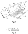
- WO 95/31805 and WO 96/01547 both concern, inter alia , loudspeaker proposals by way of piezoelectric driver patches, whether applied to panels of lids of lap-top computers or to fold-out panels of compact disc players, or within shells of video display units or disk drives of computers, or to light-weight polystyrene tiles, or supplied as an add-on sound unit for mounting to other surfaces.
- Illustrations of preferred embodiments show substantially centrally located paired piezoelectric drive patches: and much is made of such things as hollowness of associated lap-top lid, and other specific three-dimensional housings including a particularly preferred loudspeaker housing of triangular-section; also of various steps proposed for avoiding panel resonances. These latter steps are clearly merely of an ad hoc or "try-it-and-see” nature, involving the addition, as and where found to be effective, of damping and stiffening strips until sine-wave-sweep tests show unwanted vibration/resonance to have stopped.
- resonances are basic mechanisms to be positively predetermined/encouraged, including optimised/maximised in an orderly manner, for useful acoustic performance/action of panels in themselves; also positively utilised in combination with predetermined asymmetric location of advantageous carefully designed electromagnetic transducers that include moving-coil as well as piezoelectric types.
- an artificial first construct found to be of particular practical value concerns distributions of vibration anti-nodes associated with natural resonant modes, and of related dead-spots, that would theoretically arise for each of the different lengths of its sides when considered alone, i.e. each as a single axis for bending wave action, as if there could be no other bending action in the member. This is so great an over-simplification as to be surprising that any useful results arise.
- frequencies of fundamental and natural resonant modes can be calculated/computed for any dimensional values, and corresponding patterns for vibrational energies at various positions or elemental sub-areas in the transverse extent of the member concerned generated individually for any mode, including usefully presented in tables/matrices, or graphically.
- Such individual patterns for related resonant modes can be superposed at will as components of a composite pattern of at least part of notional one-axis natural bending wave action that will have complementary distributions of vibrationally more/most active regions and vibrationally less/least active regions; and selection for such modes to be superposed, thus parts of notional one-axis natural bending wave actions to be considered, is proposed on the basis of proven effectiveness for purposes hereof.
- Such composite pattern generation were used to find orthogonally related dimensional values (corresponding to the different sides of a rectangular shape) for which respective said composite patterns will, as notionally superposed, produce at least some useful degree of "matching" between the vibrationally more/most active regions of one of the composite patterns concerned and the vibrationally less/ least active regions of the other of the composite patterns concerned, and vice versa.
- This matching can be seen, albeit through admittedly artificially simplified/idealised approximation, as aimed to reduce the coincidences that would otherwise contribute to the afore-said combined dead-spots of members or panels to which teaching hereof has not been applied. Moreover, this matching can be sought to any achievable beneficial extent, including maximally or optimally for reducing or minimising notional such contributions to combined dead-spots, at least within limits of our approximations.
- the selected resonant mode frequencies for the two composite patterns involved can, preferably do, include the lower orders of interest or relevance in or to an acoustic range of desired operation, as outlined above, even including below same if beneficial.
- the resonant modes associated with is diagonal dimension.
- Assuring at least mainly helpful contribution to desired distribution(s) of resonant modes can be aided by cropping or trimming or curving of corners, or forming to such shapes, though see further below regarding anisotropy of bending stiffness.
- Sensible practical limits for consideration of this refinement as to resulting shape and transverse area reduction arise naturally from approaching some other analysable shape, e.g. super-ellipses or at least regular polygons, say preferably not reducing the diagonal beyond larger or smaller of side dimensions.
- the aforesaid construct involving generating/using data for theoretical one-axis bending wave actions for each of differing boundary-defining sides of generally rectangular members, for selected natural resonant modes; and/or cumulative superposition as composite respective patterns; and/or combination of such composite patterns to determine viable respective dimensions and/or ratio(s) of sides to desirably reduce combined dead-spots and/or effectively place anti-nodes or combined anti-nodes of one in dead-spots or combined dead-spots of the other, afford individual and/or combination aspects of this invention: as does one or more of selected orders of resonant modes being low in the range of acoustic frequencies of interest.
- Such inspection and manipulation according to varia-tion of one or more of two or more geometrical parameters may be particularly readily facilitated using a table or matrix of vibration energy contents of a grid of elemental subareas of said transverse extent, particularly by changes that take place with parameter variation, preferably as one or more ratios of such parameters. Energy summations for the subareas and generally will give required information.
- the natural bending wave vibration concerned includes resonant modes contribut-ed by hyperbolic and/or angled components from peripheral curving and going through the major and minor axes.
- the major and minor axes are found to be significant, particul-arly their ratio.
- a practical ratio of major and minor axes for true elliptical shapes has been determined at about 1.182, with a viable alternative (interestingly sim-ilarly to above for rectangular) at about 1.34.
- the value 1.1 for a / b appears unpromising.
- n and a / b may produce, whether much as in first-given above examples or going further, one or more particularly advantageous super-elliptical shape(s).
- One composite shape investigated is of substantially super-elliptical and substantially true elliptical parts merged with a common major axis favouring said elliptical part by about 1.1 - 1.3:1, and with an aspect ratio of favouring said major axis by about 1.2:1 relative to width.
- the idealised isotropic cases we analysed first thus use the same preferential aspect ratios etc as above, and gain some or most if not all the latter's beneficial acoustic action or operation, at least so long as the given shape is not too narrow to support useful complexity and interaction of its total resonant modes.
- Desired anisotropy of bending stiffnesses can be achieved by different "grain”, e.g. reinforcing fibres or lay or weave, of surfacing skins or sheets applied to a core in a said member of composite laminated sandwich structure, including differently oriented or relatively angled "grain” to each side or as multiple layers to either side.
- core-related parameters such as directionally differential shear moduli or values, that can influence bending stiffnesses.
- diagonal effective bending stiffness(es) or resistance(s) can be likewise adjusted relative to length/width bending stiffnesses (which may be equal or unequal) so as to get some if not all of benefit otherwise obtainable from shortening at corners, e.g. trimming or cropping them.
- Another way to vary bending stiffness in any direction is by curvature of the member itself, whether in only one direction or even in two or more directions, and whether along or at an angle to or transversely of any particular direction, say one or other of directions associated with parameters defining shapes and/or conceptually fundamental frequencies (hereinafter, including in the Claims, most often referred to simply as "conceptual frequencies"). It is further possible to have varying bending stiffness along any axis or direction, including progressive or otherwise over area, whether by combinations of "grains" in skin layers of sandwich structures or differences areally in core properties, say thickness decreasing or increasing from edges inwardly or whatever.
- aspects of this invention arise from predetermining differential bending stiffnesses in different directions in a said member in order to achieve at least some useful results in terms of distribution(s) of vibrational nodes and combined nodes and/or dead-spots and combined dead-spots associated with natural resonant modes and acoustic action/performance.
- aspects of invention arise from accepting, or seeking, or modifying, some effect(s), such as arising from augmenting due to edge-reflections or interaction from positional proximity or superposition of nodes for some resonant modes, or other differential effect(s) comparing one resonant mode with another; say in terms of having some particular "voicing " of the resulting acoustic performance/action of the member concerned.
- Modification can be by way of general or selective edge damping or localised medial addition of damping material, even by holes or slots formed in the member.
- An aspect of this invention also resides in seeking and assuring more even distribution of vibrational anti-nodes and/or combined anti-nodes being limited to lower orders of resonant modes, say at or up to at least third order and/or not more than seventh order (whether determined absolutely from conceptual frequencies or relative to lowest frequency modes within and/or below a frequency range of interest), including consequential effect(s) on operation at higher frequencies, and proving highly benef-icial in extending usefully achievable range of operation well above the upper frequencies considered limiting in WO/92/03024.
- More specific aspects of invention include operating over a wider frequency range than W092/03024; and/or removing its limitations to operating only above the coincidence frequency, for example to operating frequency ranges that include the coincidence frequency and/or are wholly below coincidence frequency.
- Members embodying aspects of this invention by having designedly distributed resonant modes of carefully related conceptual frequencies of natural bending wave vibration can, in themselves, serve as useful acoustic devices.
- One way is for reverberation purposes including to improve or desirably alter acoustic characteristics of some associated acoustic device, such as a conventional loudspeaker or driver unit or equipment including same.
- Another way is as an acoustic filter converting between incident and desired acoustic ranges.
- Further ways include for desirable environmental "colouring" or "voicing” purposes, say for a room, including effectively removing or compensating for unwanted effects (as could otherwise be due to room shape or proportions or contents. Such uses are referred to herein as "passive".
- Improvements hereof in determining location (s) for transducer means also began with the above construct concerning notionally unidirectional bending wave vibrations and their combination to obtain improved resonant mode distribution.
- a successful method and means for preferred transducer site identification resulted from finding those positions at which the number of dead-spots for any of the resonant modes concerned is low or least and/or the number of vibrationally active resonance anti-nodes concerned is high or highest, i.e. in terms of the resonant modes taken into account for "filling" of what would otherwise be combined dead-spots.
- each location for transducer means use two different ones of these proportional coordinates along different length sides, whether single transducer means or each of plural transducer means (as can be advantageous for power and/or frequency cover), further preferably combining 3/7 and 4/9. Close approximations to these proportionate coordinate sites came first from the above notional construct.
- transducer means Whilst such members will not be as effective as members that are preferentially proportioned as in earlier aspects of this invention, whatever potential they have for operation as loudspeakers is much better realised by applying the above dimension proportioning criteria to locating transducer means relative to one or more corners (or notional corners if subject shortening ends of one or more of its diagonals), thus leading to minimum spacing from side edges of such members of at least about 5/13 or 38% of its width and length dimensions.
- intelligible acoustic output including in rather marginal and quite lossy materials/structures, at least compared with substantially central or edge-adjacent mounting of transducer means. Tolerances mentioned later apply regarding transducer location appear capable of further relaxing, the limits being inevitably materials-dependent and feasible materials being too great fully to investigate to date.
- main series of resonant modes associated with major and minor axes are of elliptical and hyperbolic natures, as noted above, and preferential locations for transducer means are, for the above-noted 1.182 major/minor axes ratio, at coordinate positions relative to centre of about 0.43 and 0.20 along half-major and half-minor axes, respectively.
- orthogonal coordinates are not really appropriate, and it is only with appropriate coordinates, specifically elliptical/cylindrical, that values emerge for transducer locations that are of general application to other elliptical shapes, i.e.
- substantially rectangular members hereof As for substantially rectangular members hereof, more precise analysis, or experiment, can determine possible small adjustments that may be beneficial, also other site options for transducer means, including to concentrate on coupling particular resonance modes, though efficiency of operation is very much related to each transducer means coupling to as many resonant modes as practicable without adverse effects.
- transducer means are well off-centre for rectangular said members, including off centre-lines for width and length; and are further somewhat displaced from diagonals, i.e. truly asymmetric.
- preferred sites for transducer means of substantially elliptical shapes of members hereof are off-centre and off major and minor axes.
- preferred proportionate coordinates are substantially maintained regardless of isotropy/anisotropy of bending stiffnesses, directly as Cartesian coordinates for sides of substantially rectangular said members and indirectly relative to underlying elliptical/cylindrical coordinates for substantially elliptical said members.
- designated sites for at least one transducer means be of this nature, i.e. off-centre by reason of coupling at preferred combined anti-node positions, and off-axes for both substantially rectangular and substantially true elliptical shapes of members hereof, typically off-diagonal by between about 7% and about 12.5% of length and width from centre-lines, and by about 20% or more of major axis and about 10% of minor axis lengths, respectively.
- preferred sites for transducer means are not only plural in number, but are at positions well off major and minor axes or centre-lines, though generally more so, i.e. from about 10% (true ellipse minor axis) to about 35% (for super-ellipse), preferably in prescribed or prescribable manner.
- transducer means Whilst there may be complex shapes for which preferred locating sites for transducer means may be otherwise, it is an aspect of this invention, at least for preferred embodiments of generally simple shapes, to have such possible sites individually at asymmetric positions off axes or lines that join points of maximum/minimum dimensions or directions of defining geometrical parameters, and that may be in related one or more sets that, in themselves, are in centre-symmetrical or other orderly arrangement as a group for each set.
- the above relatively beneficial results from geometrical location of transducer means as herein for substantially rectangular shapes are seen as having general inventive application to panel members not proportioned etc as preferred herein.
- preferred said members hereof When used with one or more transducer means in panel loudspeakers, preferred said members hereof operative over their whole areas, i.e. up to edge boundaries as above, have bending wave vibration well distributed substantially over such whole areas from the transducer means to the edge boundaries. Moreover, resulting acoustic action need not be directional (as in US 3,347,335 above), but may be for at least part of such output of loudspeakers, e.g. if desired or required. This areal spread of bending wave vibration greatly reduces perceived proximity-dependent loud-speaker loudness effects; and, where not deliberately operative with directionality, with perceptibly much better spread than typically rather narrow and narrowing beam effect above lowest frequencies, in loudspeakers using cone elements. Moreover, resulting vibration action can, except for lowest frequencies, be used from both front and back of a said member as there will be little or none of the anti-phase problems attaching to cone element loudspeakers.
- maximum size is subject to conforming with preferred mechanical coupling to the member being at least primarily resistive and with exciting higher and lower frequency resonant modes as desired, particularly for audio usage. Whilst approximations have indicated theoretical maximum sizes at about 9% - 10% of length/width and/or major/minor axes dimensions for rectangular or elliptical/ super-elliptical shapes of said member, i.e. up to about 1% of operative transverse area, that can be exceeded at least by such as piezoelectric transducer patch-type transducers, at least up to 2% (each if plural).
- a particularly useful criterion, in practice, is that, for any particular said member or panel, there will be a size at which frequency roll-off is caused, basically as corresponding wavelengths in the panel approach and reach similar order to the size of transducer. These factors need further to be considered alongside mass considerations for moving parts of transducer means, including electromagnetic, for which a viable guide is maxima at about 1 - 2 times the mass of the part of the member that is removed for hole-mounting such active moving part or is covered by surface-mounting same.
- the range in size and/or quality can be from impressive results for such as greetings etc cards or in books etc, note-book or lap-top computers; in-car etc audio, ceiling etc tiles or wall panels, and high clarity public address systems etc; to general stereo and surround sound systems, home-movie, and hi-fi quality sound reproduction; even to such large scale applications as cinema screens and high power for outdoor or stadium concerts, including use of multiple side-by-side modules for largest applications.
- tolerances for the above-developed dimensional proportioning and transducer location criteria will be quite tight for high performance said members, say up to about 3% off for proportioning and up to about 5% off for transducer location, but much higher, say up to 5% and 10% or more, respectively for higher loss and lower performance said members.
- a remarkably wide frequency range can be handled by a single panel element, ranging from up to about 100Hz, say about 50Hz if large and/or baffled, to in excess of 15KHz, even 25KHz and higher.
- the lower limits of such operating frequency ranges are above the lowest resonant mode frequencies. Certainly, operating acoustic bandwidths in excess of 4KHz are readily achieved.
- loudspeaker units can be mounted directly against or closely adjacent solid/sound reflective surfaces.
- bending stiffness(es) and mass per unit area contribute (through square root of the quotient B/ ⁇ of the former and the latter) along with dimensions/area to setting lowest true bending wave frequencies, with Young's modulus (E) and thickness of skins of sandwich structures of the members as well as the square of their core thickness having particularly relevant effects on bending wave stiffness.
- Said bending wave stiffness(es) and mass per unit area also contribute, through square root of inverse ⁇ /B of above quotient, along with the ratio of squares of speed of sound in air and (by bending waves) in the members, to setting the actual coincidence frequency, with core shear modulus (G) and core thickness (d) contributing to said ratio along with said of mass per unit area ( ⁇ ) being particularly influential as the actual coincidence frequency is always greater than results from much simpler notional calculation assuming no core shear thus no account taken of said ratio. Lowering or raising the coincidence frequency can be by raising or lowering said ratio.
- core shear modulus G
- core shear modulus G
- core shear modulus G
- Relatively lower and highervalues result in greater and lesser, respectively, transmission of energy applied by the transducer means in core shear waves rather than desired skin bending waves.
- Such shear waves do not radiate sound, and nett acoustic result of lower core shear modulus values is that the effective sound radiating areas of the members tends to reduce with frequency, though still substantially larger than any parallel with conventional cone-element tweeters resembling a highly directional point source.
- piezoelectric transducer means as particularly suited to card or book, even notice-board, embodiments typically of the order of about A5 to about A4, even to A1, sizes preferably with coincidence frequency as high as 20KHz or more and operating frequency range going from between about 200Hz and 350Hz up to about 15Khz or so, and related lowest resonant modes concerned at about 100Hz to about 250Hz.
- satisfactory lightweight core materials will generally be of expanded foamed synthetic plastics materials or of honeycomb or other open-work form fabricated from sheet materials, see further later.
- Such structures give rise to further factors involving skin and core properties, both alone and in conjunction with each other and/or with size and mass of active parts of transducer means, including the possibilities of further resonances such as affected by core compliance along with skin and/or transducer part mass(es), specifically resonances from size/volume of core cells and/or from compliant core compression/recovery and/or from skin portions overlying open core cells potentially with tiny drum-like subsidiary vibration effects, etc.
- Such further resonances can be useful, i.e. be positive factors in materials selection/specification, by contributing to, even extending, actual operating frequency range, usually at the higher end, typically approaching or above 20KhZ, say 19Khz - 22KHz. If those further resonances would not be useful, even be deleterious, to performance, that can be taken into account for avoidance in selection etc of materials.
- Desired or effectively required sizes and shapes are obvious design factors, and bring in anisotropy, as to which it can be relevant that at least some of available honeycomb have, certainly can have, different shear moduli in different directions. Possibilities obviously arise as to incorporation of members hereof into host sheets or panels and as to defining operational areas by deformation or added defining material as mentioned above.
- Desired type etc of transducer means even viability effectively forcing or limiting choice thereof, is/are further key consideration(s), including as to compliance of mounting at least active moving part(s) thereof to or into members hereof, as to normal requirement for predominantly resist; ive rather than reactive mechanical coupling of transducer part(s) to such members, and as to output power desiderata thus input power and forces applied by moving part(s) of transducer means being desirably consistent with buckling etc characteristics/resistance of core materials.
- transducer means are, of course, feasible. Then, it is particularly preferred that multiple transducer means be used, preferably to get the best possible sampling of possible active resonant modes, say where appropriate, with transducer means at least one of each of progressively outward different ones of preferential locations.
- the reverse or inverse action compared with loudspeakers hereof can produce signals capable of intelligible reproduction and/or ready meaningful input to data processing machines.
- capability of combining through additional transducer means on a member hereof also operating as a loudspeaker has advantages, as has provision orfurther combination with or as cladding or a casing.
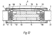
- transducer means two particular types have been mentioned, namely piezoelectric, and electromagnetic with specific reference to what is effectively continuation of long-established practice for cone-element loudspeakers by way of moving coil means being fixed/bonded -on, say acting against mass of magnet means also carried by the member, with passing reference to alternative use of moving magnet means the excitation purposes hereof.
- another transducer means aspect of this invention concerns addition to operatively moving part(s) of transducer means of more mass, including where such addition is substantially medially of such parts actually mounted to members hereof beyond or outside such additional mass, say peripherally, preferably at or adjacent edges thereof at or adjacent edges of wells or apertures in members hereof with said additional mass projecting into such wells or apertures, further preferably with appropriate clearance therein, particularly advantageously mounted to skins and extending into cores of preferred laminated sandwich structures for members hereof.
- the word "resonate” is used, as a descriptive and semantically accurate convenient short-hand term for such desired or acceptably achievable areally distributed and orderly natural resonant mode related bending wave vibration, involving the positive and deliberate encouragement by design of such resonance-based vibration; and is not to be confused with other usages of that word in other connections where any vibration is considered inherently problematic (and, perhaps, as often as not actually related to inaccuracies and/or wear of cooperating parts !).
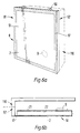
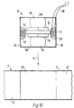
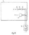
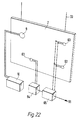
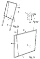
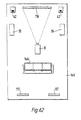
- a panel-form loudspeaker (81) comprises a rectangular frame (1) carrying a resilient suspension (3) round its inner periphery which supports a distributed mode sound radiating panel (2) formed structurally and configured as variously developed above.
- a transducer (9), e.g. as described later with reference to Figures 9 - 17, is mounted wholly and exclusively on or in the panel (2) at a predetermined location defined by dimensions x and y .
- the latter are, of course the proportionate side length coordinates (from any corner) as indicated above. Conversion to being centre-related coordinates could be of general value, e.g.
- the transducer (9) serves to launch or excite bending waves in the panel to cause the panel to resonate and radiate an acoustic output; and is shown driven by a signal amplifier (10), e.g. an audio amplifier, connected to the transducer by lead conductors (28).
- a signal amplifier (10) e.g. an audio amplifier
- Amplifier loading and power requirements can be similar to conventional cone type speakers, sensitivity being of the order of 86 - 88dB/watt under room loaded conditions.
- Amplifier load impedance is largely resistive at 6 ohms, and power handling 20-80 watts.
- the panel core and/or skins are of metal, they may serve as a heat sink for the transducer, say to remove heat from a voice coil of the transducer, and thus improve power handling.
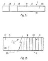
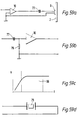
- Figures 2 a and 2 b are partial typical cross-sections through the loudspeaker (81) of Figure 1.
- Figure 2a shows that the frame (1), surround (3) and panel (2) are connected together by respective adhesive-bonded joints (20).
- Suitable materials for the frame include such as used in picture framing, say of extruded metal (e.g. aluminium alloy) or plastics, etc.
- Suitable surround materials can meet desiderata above and include resilient materials such as foam rubber and foam plastics.
- Suitable adhesives for the joints (20) include epoxy, acrylic and cyano-acrylate etc. adhesives.
- Figure 2 b illustrates, to an enlarged scale, that the panel (2) is a rigid lightweight laminated sandwich-type panel having a core (22) e.g. of rigid plastics foam (97) or cellular matrix (98) such as a honeycomb matrix of metal foil, plastics or the like, with the cells extending transversely to the plane of the panel, and closed by opposed skins (21), e.g. of paper, card, plastics or metal foil or sheet.
- a core (22) e.g. of rigid plastics foam (97) or cellular matrix (98)
- a honeycomb matrix of metal foil, plastics or the like such as a honeycomb matrix of metal foil, plastics or the like
- the skins are of plastics, they may be reinforced with fibres e.g. of carbon, glass, Kevlar or the like in a manner known per se to improve their tensile properties.
- Envisaged skin layer materials and reinforcements thus include carbon, glass, Kevlar (RTM), Nomex (RTM) or aramid etc, fibres in various lays and weaves, as well as paper, bonded paper laminates, melamine, and various synthetic plastics films of high modulus, such as Mylar (RTM), Kaptan (RTM), polycarbonate, phenolic, polyester or related plastics, and fibre reinforced plastics, etc. and metal sheet or foil.
- Additional moulding for plain or reinforced plastics would allow for mould tooling to carry location and registration features, such as grooves or rings for the accurate location of transducer parts, e.g. excitation coil and/or magnet suspension.
- location and registration features such as grooves or rings for the accurate location of transducer parts, e.g. excitation coil and/or magnet suspension.
- Envisaged core layer materials include fabricated honeycombs or corrugations of aluminium alloy sheet or foil, or Kevlar (RTM), Nomex (RTM), plain or bonded papers, and various synthetic plastics films, as well as expanded or foamed plastics or pulp materials, even aerogel metals if of suitably low density.
- Some suitable core layer materials effectively exhibit usable self-skinning in their manufacture and/or otherwise have enough inherent stiffness for use without lamination between skin layers.
- a high performance cellular core material is known under the trade name 'Rohacell' which may be suitable as a radiator panel and which is without skins. In practical terms, the aim is for an overall lightness and stiffness suited to a particular purpose, specifically including optimising contributions from core and skin layers and transitions between them.
- piezoelectric transducers and ferromagnetic electro-magnetic transducers have negligible electromagnetic radiation or stray magnetic fields.
- Conventional speakers have a large magnetic field, up to 1 metre extent unless specific compensating countermeasures are taken.
- electrical connection can be made to the conductive parts of an appropriate DML panel or an electrically conductive foam or similar interface may be used for the edge mounting.
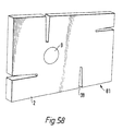
- the suspension (3) may damp the edges of the panel (2) to prevent excessive edge movement of the panel without generally preventing desired edge vibration. Additionally or alternatively, further damping may be applied, e.g. as patches, bonded to the panel in selected positions, see dashed at 2P, to control particular frequency modes in damping excessive movement, and help distribute resonance more equally over the panel.
- the patches may be of bitumen-based material, as commonly used in conventional loudspeaker enclosures or may be of a resilient or rigid polymeric sheet material. Some materials, notably paper and card, and some cores may be self-damping. Where desired, the damping may be increased in the construction of the panels by employing resiliently setting, rather than rigid setting adhesives.
- Effective said selective damping includes specific application to the panel including its sheet material of means permanently associated therewith. Edges and corners can be particularly significant for dominant and less dispersable low frequency vibration modes of panels hereof. Edge-wise fixing of damping means can use-fully lead to a panel with its said sheet material fully framed, though at least their corners can often be relatively free, say for desired extension to lower frequency operation. Attachment can be by adhesive or self-adhesive materials. Other forms of useful damping, particularly in terms of more subtle effects and/or mid- and higher frequencies can be by way of suitable mass or masses affixed to the sheet material at effective medial localised positions of said area.
- An acoustic panel hereof is truly bi-directional.
- the sound energy from the back is not strongly phase-related to that from the front. Consequently there is the benefit of overall summation of acoustic power in the room, sound energy of uniform frequency distribution, reduced reflective and standing wave effects, and the advantage of good reproduction of the natural space and ambience in the reproduced sound recordings.
- acoustic panel members hereof will normally be sized including adjustment as to differential bending stiffnesses to make a match with resonantly outer operative area, that is not essential.
- Other measures, indicated dashed in Figures 2 a and 2 b include cutting partially (22C) into the core (22) through one skin 21 or adding damping or stiffening material/members (22S) as inner framing at least partially about the intended operative area, thereby reducing some of preferential size for the panel member structure concerned.
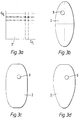
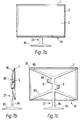
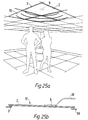
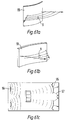
- Figure 3 a shows preferential transducer locations for a substantially rectangular panel member as indicated above, for isometric aspect ratio of 1.34:1, namely at crossings'x'of orthogonal coordinates taken from 3/7, 4/9 and 5/13 of lengths of sides from its comers, other corners being as illustrated for just one one quadrant.
- the six transducer locations for any corner on a reference are to be implied as represented either individually or collectively (but used individually within each "collection" relative to centring a transducer thereat).
- Figures 3 c and 3 d likewise show substantially super-elliptical and part super-elliptical/part-elliptical panel shapes, each with the preferred transducer locations being as indicated above, but only shown in approximate outline.
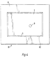
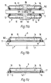
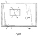
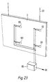
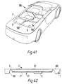
- Figure 4 shows a first distributed mode panel-form loudspeaker (81) generally of the kind shown in Figures 1 and 2 and in which the frame (1) is 5 replaced by a baffle-board (6), e.g. of medium density fibreboard, having a rectangular aperture (82) in which a distributed mode radiator panel (2) is mounted with the interposition of a resilient suspension (3).
- the baffle-board (6) can help with low frequencies and/or if very close to a wall.
- a transducer (9) as described for Figures 9 - 17 is mounted wholly and exclusively on the panel (2) to excite the panel to cause it to resonate to produce an acoustic output.
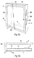
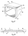
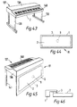
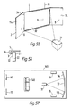
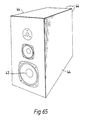
- the loudspeaker comprises a shallow box-like enclosure (8) having a top (148), a bottom (149), opposed sides (150); a back (151) and a front (152).
- the front (152) of the enclosure (8) consists of a rigid lightweight distributed mode radiator panel (2) of the kind described with reference to Figures 1 and 2 and comprising a core (22) enclosed by opposed skins (21).
- the panel (2) is supported in the enclosure (8) by means of a surrounding compliant suspension (17), e.g. a strip of latex rubber.
- a transducer (9), e,g, of the kinds described for Figures 9 - 17 is mounted wholly and exclusively on the inwardly directed face of the panel (2) in a predetermined location as discussed above, to excite bending wave vibration in the panel to cause it to resonate to produce an acoustic output.
- the enclosure (8) may be formed with ports (109) e.g. in one side (150), to enhance bass performance of the loudspeaker, including of some pistonic action allowed by compliance of panel mounting in the box.
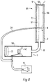
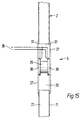
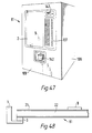
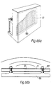
- FIG 6 illustrates a further loudspeaker (81) generally similar to that described above with reference to Figure 5.
- the loudspeaker comprises a box-like enclosure (8) consisting of a front box portion (52) adapted to be mounted on a wall and a separable rear box portion (110) adapted to be set into a wall, e.g. a stud-work wall to further reduce the already shallow apparent depth of the loudspeaker enclosure.
- the front face (51) of the front box consists of a rigid lightweight multi-mode radiator (2) comprising, as for Figure 3, a core (22) enclosed by opposed skins (21 ).
- the panel (2) is supported in the enclosure (8) by means of a surrounding resilient suspension (17), e.g. of rubber latex strip.
- the loudspeaker is thus generally of the kind described with reference to Figures 1 and 2 above.
- a transducer (9), e.g. of the kind described for Figures 9 - 17 is mounted wholly and exclusively on the inwardly directed face of the panel (2) in a predetermined location as discussed above to excite and vibrate the panel in bending wave mode to cause it to resonate to produce an acoustic output.
- Such loudspeakers are relatively simple to make and can be made to have a relatively shallow depth, or apparently shallow depth, in comparison to conventional loudspeakers; and have a wide angle of dispersion in comparison to conventional pistonic loudspeakers.
- the radiator panel is made from or is skinned with metal foil or sheet, the loudspeaker can be made to be shielded against radio-frequency emissions.
- a panel-form loudspeaker comprising a resonant multi-mode acoustic radiator, drive means mounted to the radiator to excite multi-mode resonance in the radiator, and a baffle surrounding and supporting the radiator: for which resilient suspension may be interposed between the radiator and the surround, typically an elastomeric material such as rubber, and may be sponge-like, e.g. foamed rubber; the baffle may be substantially planar or may be in the form of an enclosure, e.g. a box-like enclosure, and of any suitable rigid material, e.g.
- medium density fibreboard including formed into an enclosure as of so-called 'infinite baffle' form and/or or ported; the transducer may be mounted wholly and exclusively on the radiator; the enclosure may comprise a rear box portion adapted to be buried in a wall or the like surface and a front box portion adapted to project from the wall or the like, and such two box portions may be physically separable and adapted to be connected together in desired fashion.
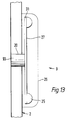
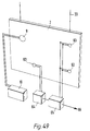
- Figure 7 shows a floor-mounted panel-form loudspeaker (81), i.e. as generally shown in Figures 1 and 2, as a lightweight rigid rectangular distributed mode sound radiating panel (2) mounted in or on a resilient surround (3) shown supported in a rectangular frame (1) on a floor stand (23) having a ground-engaging foot (83) and an upright stem (84) to four generally horizontal arms (85) connected at their distal ends (86) to the respective corners (87) of the frame (1).
- a balanced pair of transducers (9) of the kind shown in Figures 9 - 17 are mounted at one respective end on the panel (2) with their other ends also supported on lugs (88) on the stem (84) to drive the panel.
- the pair of transducers (9) are located on the panel (2) at predetermined locations as above.
- This arrangement is intended to operate to drive the panel (2) pistonically at low frequencies by reacting against the stem (84) which along with the arms (85) acts as the chassis of a conventional loudspeaker drive unit, but launch/excite bending wave vibration the panel at other than low frequencies of pistonic action, i.e. to resonate for corresponding acoustic output.
- the suspension (3) will be compliant, i.e. like the roll surround of a conventional pistonic loud-speaker cone driver.
- Such panel-form loudspeakers are relatively simple to make, and flatness makes them relatively easy to house, and there is a wide angle of acoustic dispersion in comparison to conventional loudspeakers.
- particular device aspects of this invention include a panel-form loudspeaker as a resonant distributed mode acoustic radiator having a periphery, a transducer mounted to the radiator to excite distributed mode resonance in the radiator, and a frame supporting the radiator, the transducer being coupled between the radiator and the frame to vibrate the panel to cause it to resonate to produce an acoustic output, wherein frame means supports the radiator at its periphery, preferably for additional pistonic acoustic action, conveniently with resilient suspension means couples between the frame and the radiator periphery; and/or the frame having a portion surrounding the radiator panel and/or the resilient suspension of elastomeric material.
- the transducer being adapted both to cause the radiator to resonate and to move the radiator pistonically is a particular inventive feature, as is the frame comprising a floor stand having a ground engaging portion, a substantially upright portion extending from the ground engaging portion and a plurality of arms extending from the upright portion, the distal ends of which arms carry the resilient suspension.
- the radiator can be any shape preferably held peripherally by the arms, conveniently with transducer(s) mounted on or adjacent to the upright portion of the frame.
- Figure 8 shows another way of combining pistonic and distributed mode resonant behaviour for a loudspeaker (81).
- Lightweight, rigid distributed mode sound radiator panel (2) forms a front wall of a box-like enclosure (8) having sides (135) and a rear wall (12), e.g. of medium density fibre-board, together defining a cavity (155).
- a panel (51) of acoustic absorption material is provided in the cavity (155).
- a panel (51) of acoustic absorption material is provided in the cavity to damp standing waves.
- the radiator panel (2) is mounted in the enclosure (8) by means of a compliant suspension (7) e.g. to emulate the roll surround of a conventional pistonic cone loudspeaker and carries a transducer (9) as in Figures 9 - 17 mounted wholly and exclusively on the panel (2) at a predetermined location as described above.
- the interior cavity (155) of the enclosure (8) is coupled to a bass pump (11), that is to say to the interior of a box-like enclosure (185) containing a pistonic bass loudspeaker drive unit (42), by means of pipe-like conduit (90), whereby air pressure waves of acoustic frequency in the bass region are applied to the interior (155) of the enclosure to cause the panel (2) to move pistonically on its compliant suspension (7) to produce a low frequency acoustic output.
- the panel is caused to resonate by the transducer (9) to cause the panel to radiate an acoustic output at higher frequencies.
- An amplifier (1) is arranged to feed an acoustic signal to the bass pump (11 ) and to the transducer (9) to drive the loudspeaker.
- a loudspeaker comprising an enclosure, an acoustic radiator in the enclosure, a compliant suspension mounting the radiator in the enclosure for limited pistonic movement relative thereto, and transducer means for driving the radiator, wherein the radiator is a panel-form distributed mode acoustic radiator, by a first transducer mounted wholly and exclusively on the radiator to vibrate the radiator to cause it to resonate, and by means for varying the air pressure in the enclosure to cause the radiator to move pistonically; where the air pressure varying means may comprise an air pump, say as a subsidiary enclosure, a pistonic driver mounted in the subsidiary enclosure and means coupling the interiors of the respective enclosures such that air pressure waves produced by motion of the pistonic driver are transmitted to the said enclosure; and acoustically absorbent means, e.g. wadding, may be provided in the said enclosure and/or in the subsidiary enclosure.
- Figure 9 shows moving coil transducer (9) arranged to be embedded entirely within interior of stiff lightweight distributed mode panel (2) comprising a core (22) faced on both sides with skins (21) to excite/launch bending waves in the panel.
- the transducer comprises a coil (13) embedded in a fixing (16), e.g. of epoxy resin, in a cavity (29) in the core (22) of the panel (2), and surrounding a cylindrical coil former (18), the coil (13) and former (18) thus being rigidly fixed in the panel (2).
- a fixing (16) e.g. of epoxy resin
- a magnet assembly comprising an opposed pair of magnets (15) separated by a pole-forming member (14), the magnet assembly being mounted on the inner faces of skins (21) of the panel (2) by means of opposed compliant suspension members (19) of rubber-like material, e.g. foam rubber, which are adhesively bonded to the magnet assembly and to the interior surfaces of the respective skins (21) of the panel.
- the magnet assembly (14,15) is thus mounted concentrically of the coil (13) and is axially movable on its suspension (19).
- the transducer (9) operates to launch/excite bending waves in the panel (2) by vibrating to cause local resilient deformation of the panel due to relative axial motion between the magnet assembly and the coil.
- the drive/excitation effect is enhanced by increasing the mass of the magnet assembly.
- the mass of the magnet assembly In operation, at least at high frequencies, since the mass of the magnet assembly is relatively large in comparison to that of the panel, the inertia of the magnet assembly will tend to hold the magnet assembly stationary and to vibrate the panel relatively thereto.
- Figure 10 shows a moving coil transducer (9) similar to that shown in Figure 9 and arranged to be embedded entirely within the interior of a stiff lightweight distributed mode radiator panel (2) comprising a core (22) faced with skins (21) to launch bending waves into the panel.
- the transducer (9) is formed as a modular assembly to facilitate its assembly into a panel (2).
- the panel (2) is formed with a suitable cavity (120) to receive the transducer (9).
- the transducer comprises a coil (13) fixed to the interior wall of a cylindrical coil former (18) e.g.
- the former (18) providing the outer casing of the transducer and being closed at its opposite axial ends by lightweight end caps (119) which are rigidly fixed to the coil former in any desired fashion, e.g. by means of adhesive bonds (220).
- the assembly is arranged to be located in the transducer cavity (120) in a distributed mode panel (2), by movement in direction of arrow 'A' as indicated in.
- the transducer is fixed in the cavity by means of an adhesive.
- a magnet assembly comprising an opposed pair of magnets (15) separated by a pole-forming member (14), the magnet assembly being mounted on the end caps (119) of the coil former (18) by means of opposed compliant suspension members (19) of rubber-like material, e.g. foam rubber, which are adhesively bonded to the magnet assembly and to the interior surfaces of the respective end caps.
- the magnet assembly (14, 15) is thus mounted concentrically of the coil (13) and is axially movable on its suspension (19).
- the transducer (9) operates to launch/excite bending waves in the panel (2) by vibrating to cause local resilient deformation of the panel in the same way as described above with reference to the embodiment of Figure 9.
- the transducer (9) of Figure 10 is intended as a low profile device which can be buried substantially within the thickness of a distributed mode panel (2).
- the transducer comprises a cylindrical coil former (18) adapted to be fixed, e.g. by means of an adhesive, in a corresponding aperture (29) in the panel (2).
- a coil (13) is secured to the interior face of the former (18) e.g. with the aid of an adhesive.
- the opposed axial ends of the former (18) are closed by disc-like compliant suspension members (59), e.g. of rubber or the like, each of which is formed with an annular corrugation (136) near to its periphery to form a roll surround similar to that used on conventional pistonic cone loudspeaker drive units.
- the peripheries of the members (59) are secured to the axial ends of the coil former (18) e.g. by clamping, with the aid of an adhesive or in any suitable fashion.
- the centre portions of the members (59), which centre portions are defined by the annular corrugations (136) carry between them a magnet assembly comprising an opposed pair of magnets (15) sandwiching a pole piece (14).
- the outer faces of the magnets (15) are bonded or otherwise secured to the centre portions of the members (59), whereby the magnet assembly (14,15) is located concentrically with respect to the coil (13) and is capable of limited axial movement relative thereto.
- the magnet assembly is shielded by means of disc-like screens (121) mounted on annular resilient members (17) supported on the panel (2) to prevent or limit the stray magnet field surrounding the panel adjacent to the transducer.
- the transducer arrangement (9) of Figure 11 a comprises complementary push/pull drivers disposed on opposite sides of the panel (2) to launch bending waves into a rigid lightweight distributed mode radiator (2) comprising a core (22) enclosed by opposed skins (21), to cause the panel to resonate.
- Coils (13) are rigidly fixed, e.g. by means of an adhesive, on the outside of a coil former (18) to form a voice coil assembly which is rigidly bonded to the opposed surface skin (21) of the radiator panel (2), e.g. by means of an epoxy adhesive bond (16).
- a fixing member (93) which is generally cylindrical in shape is arranged to pass freely through an aperture (29) in the panel (2).
- the fixing member (93) comprises opposed generally complementary parts each formed with a head (95) which are clamped against the axial extremities of the respective pair of transducers (9) to couple the drivers together.
- the complementary parts of the fixing member (93) are secured together by complementary screw-threaded portions (160, 161).
- the fixing member may be of any suitable material e.g. plastics or metal.
- the transducer arrangement (9) of Figure 11 a is not rigidly clamped to the panel (2) adjacent to the aperture (29) but is instead coupled to the panel via resilient pads (17) e.g. of foam rubber positioned close to the panel aperture (29) in much the same manner as is shown with reference to Figures 3 and 3 whereby the transducer works to launch bending waves into the panel by inertial effects due to the combined mass of the respective drivers.
- the transducer (9) of Figure 11 b is generally similar to that of Figure 11 a but is intended for attachment to only one side of a panel (2).
- the magnet assembly (14,15) is secured to the surface of the panel (2) by means of a resilient suspension (17) e.g. of rubber, which is attachedtothe periphery of the flange (162) of the outer pole pieces (14).
- Figure 11c shown a transducer (9) of the kind shown in Figure 11 b and intended for easy application to a panel surface.
- the transducer (9) is mounted, by way of the former (18) and resilient suspension (17) on a thin substrate (147) formed with a self adhesive outer layer whereby the transducer can be mounted in position.
- an inertial vibration transducer comprising a voice coil assembly has a tubular member and a coil rigidly fixed to the tubular member, a magnet assembly disposed concentrically within the voice coil, and resilient means supporting the magnet assembly for axial movement relative to the voice coil, the voice coil being adapted to be rigidly mounted to a distributed mode radiator: where the resilient means may comprise opposed elastomeric members; the axial ends of the voice coil may be closed by caps; and the resilient means may be mounted on the caps; the coil may be mounted on the inner face of the tubular member to form the voice coil assembly and/or be adapted for reception in a correspondingly shaped cavity in the radiator; the caps may comprise the resilient means, say each comprise an annular compliant roll surround; and magnetic shields may be disposed over the caps to reduce stray magnetic fields.
- the voice coil assembly may be adapted to be rigidly fixed to a face of the radiator and/or the magnet assembly may comprise opposed generally disc-like pole pieces, the periphery of one of which is disposed within and adjacent to the voice coil assembly, the periphery of the other of which pole pieces being formed with a flange arranged to lie adjacent to and to surround the voice coil assembly; and/or the resilient member may be sandwiched between one of the pole pieces and a face of the radiator and/or the transducer may comprise complementary magnet assemblies and voice coil assemblies on opposite faces of the radiator, and means tying the magnet assemblies together for push-pull operation.
- loudspeaker comprising an inertial transducer as indicated and/or described above, and a loudspeaker comprising a distributed mode acoustic radiator and the transducer being coupled to vibrate the radiator to cause it to resonate.
- Figure 13 shows a piezo-electric transducer (9) in which a crystalline disc-like piezo bender (27) is mounted at its centre on one end of a lightweight rigid cylindrical block (93) of rigid foam plastics which is rigidly fixed in an aperture (20) in a distributed mode radiator panel (2) e.g. by means of an adhesive, the said one end of the block (28) projecting from the face of the panel (2) so that the periphery (31) of the bender (27) is freely suspended adjacent to a face of the panel (2).
- An annular ring (25) of plastics, e.g. mineral loaded polyvinylchloride is rigidly fixed to the periphery of the piezo bender (27) to add mass to the free periphery of the pi-ezo bender.
- the piezo bender (27) vibrates and due to its mass launches bending waves into the panel (2) to cause the panel to resonate and produce and radiate an acoustic output.
- the transducer (9) may be covered by a domed housing (26) which is fixed to the panel (2) to protect the transducer.
- the piezo-electric transducer (9) of Figure 14 has a disc-like piezo bender (27) fixedly mounted by its periphery (31) on the surface of a panel (2) e.g. with the aid of an adhesive, with the central portion of the bender (27) freely suspended over a cavity (29) in the panel (2) such that only the periphery (31) of the bender (27) is in contact with the panel.
- a mass (25) e.g. of plastics material is attached to the centre of the bender (27) with the interposition of a damping pad (30) of resilient material, e.g. of an elastic polymer.
- a damping pad (30) of resilient material e.g. of an elastic polymer.
- the transducer arrangement (9) of Figure 15 is similar to that of Figure 14 except that in this embodiment a pair of piezo benders (27) are attached on opposite sides of a cavity (29) through a panel (2) to operate in push/pull mode. In this arrangement, the centres of both benders (27) are connected together by a common mass (25) with resilient damping pads (30) positioned between each bender (27) and the mass (25).
- Such transducers are relatively simply in construction and are effective in use.
- particular device aspect of this invention includes an inertial vibration transducer having a plate-like piezoelectric bender and means adapted to mount the bender on a member to be vibrated, the arrangement being such that a substantial part of the bender is spaced from the member for movement relative thereto; where a mass may be secured to the said substantial part of the bender, which may be of crystalline form, say disc-like; the mounting means may be disposed centrally thereof; and the mass may be secured to the periphery of the bender.
- the peripheral margin of the disc-like bender may be fixed to the member, and the mass may be secured to the centre of the bender.
- a resilient member may be employed to attach the mass to the bender; and benders as described may be attached to opposite sides of the member to be bending wave vibrated and coupled together by a common mass to operate in push/pull mode.
- a loudspeaker has a distributed mode acoustic radiator with a transducer as described above coupled to vibrate/excite the radiator in bending wave mode.
- Figure 16 shows a transducer (9) for exciting/launching bending waves in rigid lightweight distributed mode radiator panel (2), as shown in Figures 1 and 2, comprising a core (22) enclosed by opposed skins (21), to cause the panel to resonate.
- the transducer comprises a coil (13) rigidly fixed, e.g. by means of an adhesive, on the outside of a coil former (18) which is rigidly bonded to a surface skin (21) of the radiator panel (2), e.g. by means of an epoxy adhesive bond (16).
- a magnet (15) is enclosed by a pair of poles (14), one of which is disc-like and is disposed with its periphery close to the interior of the coil former (18), and the other of which has a peripheral flange (90) arranged to surround the coil (13).
- the magnet assembly including the magnet (15) and poles (14) is mounted on the panel (2) by means of a fixing (93), e.g. of metal or hard plastics, which passes through a cavity (29) extending through the panel (2).
- the fixing (93) comprises a complementary pair of threaded members (91,92) each having heads (95), one of which heads bears against an outer face of the transducer (9) and the other of which heads bear against a face of the panel (2) on the side of the panel opposite to that on which the transducer is mounted.
- a spacer (127) is trapped between the transducer (9) and the panel (2) to spruce the transducer from the panel.
- This transducer (9) operates by locally resiliently bending the panel between the fixing (93) and the former (18) when an acoustic signal is applied to the transducer to launch/excite bending waves in the panel to cause it to resonate.
- the transducer arrangement (9) of Figure 17 is similar to that described in Figure 16, except that the transducer comprises complementary push/pull drivers of the kind shown in Figure 16 disposed on opposite sides of the panel.
- a fixing member (93) is arranged to pass through an aperture (29) in the panel (2) to tie the two transducers together and to the panel.
- the fixing member (93) comprises opposed generally complementary parts each formed with a head (95) which are clamped against the axial extremities of the respective pair of transducers (9) to couple the drivers together.
- the complementary parts of the fixing member (93) are secured together by complementary screw-threaded portions (94,96).
- the fixing member may be of any suitable material e.g. plastics or metal.
- the transducer device (9) is rigidly clamped to the panel (2) by means of rigid pads (19), e.g. of hard plastics, positioned between the panel and the poles (14) adjacent to the aperture (29), whereby the transducer works to launch bending waves into the panel by local resilient bending of the panel between the pads and the coil former (18).
- rigid pads (19) e.g. of hard plastics
- a vibration transducer to vibrate a member, such as inducing bending wave action in a said member hereof, having a face, wherein a voice coil assembly has a coil rigidly fixed to a tubular member, the assembly being adapted to be fixed to the said face of the member, and by a magnet assembly comprising opposed disc-like pole pieces, the periphery of one of which pole pieces is arranged to be disposed with and adjacent to the voice coil assembly, and the periphery of the other of which pole pieces is formed with a surrounding flange adapted to surround and to be disposed adjacent to the voice coil assembly; and wherein the magnet assembly is adapted to be secured at its centre to the said member to be vibrated; and/or the transducer may comprise fixing means to secure the magnet assembly to the member, and/or the fixing means may comprise a fastener adapted to engage in a cavity in the member, and/or the fastener may comprise a spacer for spacing the peripheries of the pole pieces
- Figure 18 shows a panel-form loudspeaker (81) generally similar to that of Figures 1 and 2 and in which the distributed mode panel (2) is formed with a generally rectangular aperture (82) within its boundaries in which is mounted a second distributed mode sound radiating panel (4) with a resilient suspension (3) interposed between the respective panels.
- the panel (4) is constructed in the same manner as the panel (2), e.g. with a central core (22) separating skins (21).
- the panel (4) is driven by its own transducer (9) mounted wholly and exclusively on or in the panel (4) at a predetermined location to produce a high frequency acoustic output, while the panel (2) is driven by a separate transducer (9) to produce an acoustic output of lower frequency, so that the loudspeaker can readily encompass the whole acoustic spectrum.
- Figure 19 illustrates how a distributed mode panel (2) hereof, or example of the kind shown in Figures 1 and 2, can be driven to resonate by a pair (70,71) of transducers (9).
- the smaller one of the transducers (70) is a high frequency piezoelectric transducer, e.g. of the kind shown in Figure 24; and the larger one of the transducers (71) is of the electrodynamic kind, e.g. as shown in Figures 9 - 17
- the transducers (70,71) are driven by an amplifier (10) coupled in parallel to the respective transducers with the interposition of a step-up transformer (72) and matching resistance (73) in the line to the piezo transducer in view of its relatively high voltage requirement.
- Figure 20 illustrates how a distributed mode panel (2) hereof, e.g. of the kind shown in Figures 1 and 2, can be driven by a pair (70,74) of transducers (9), the transducer (70) being a high frequency piezo-electric transducer e.g. of the kind shown in Figure 24 and the transducer (74) being a low frequency piezo-electric transducer of the kind shown in Figures 13 -15.
- Reference (75) indicates that the transducer (74) is weighted with a mass to increase its inertia.
- the transducers (70,74) are driven by an amplifier (10) to which they are connected in parallel, with resistors (78) interposed to provide a frequency dividing network.
- Figure 21 illustrates how a distributed mode panel (2) hereof, e.g. of the kind shown in Figures 1 and 2, can be driven by a pair (68,69) of electrodynamic transducers, e.g. of the kinds shown in Figures 9 - 17.
- Thetransducer (68) is intended as a high frequency driver and is thus of low inductance, whereas the transducer (69) is intended as a low frequency driver and is of high inductance.
- the transducers (68,69) are driven in parallel by an amplifier (10) with a capacitor (77) in the line to the transducer (68) to act as a frequency divider to pass most of the high frequency signal to the transducer (68).
- Particular inventive device aspects include a panel-form loudspeaker having a distributed mode acoustic radiator and a first transducer coupled to the radiator to excite distributed mode resonance in the radiator, and having a second transducer coupled to vibrate the radiator; where the first and second transducers may be adapted to operate in different frequency ranges; where one of the transducers may be of electromagnetic type and/or one of the transducers be of piezoelectric type; the panel-form loudspeaker may have a second distributed mode acoustic radiator mounted on or in the first said radiator, and resilient suspension coupling between the first and second radiators, the first transducer being mounted wholly and exclusively on the first radiator and the second transducer being wholly and exclusively mounted on the second radiator and/or the second radiator mounted in an aperture in the first radiator.
- Figure 22 shows a distributed mode panel (2) hereof, say as for Figures 1 and 2, intended for use both as a loudspeaker and as a sound receiver or microphone, e.g. for use in an interactive environment.
- the panel (2) is mounted in a surrounding frame (1) and is attached to the frame via a resilient suspension (3) in the manner shown in Figures 1 and 2.
- the frame is suspended on a pair of wires (33), e. g. from a ceiling or on a floor standing frame (not shown).
- the panel is driven to resonate and produce an acoustic output by a transducer (9) which in turn is connected to and driven by an amplifier (10).
- the panel also carries a pair of vibration sensing transducers (63), which may be piezo-electric benders as illustrated earlier, and are coupled in parallel to drive a signal receiver and conditioner (65) connected to an output (66).
- Another vibration transducer (63) on the panel (2) e.g. as earlier discussed, is coupled to drive a filter/correlator the output from which is fed to the signal receiver and conditioner (65), to provide signal correction.
- Such simple loudspeaker/microphone has wide scope for industrial application, e.g. for use in an inter-active environment.
- a particular device aspect of this invention arises as a panel-form loudspeaker having a distributed mode acoustic radiator and a transducer coupled to vibrate the radiator to cause it to resonate, wherein a second transducer is coupled to the radiator to produce a signal in response to resonance of the radiator due to incident acoustic energy; preferably with the distributed mode acoustic radiator mounted in a surrounding frame by means of an interposed resilient suspension, and/or having at least two said second transducers at spaced locations on the radiator, and/or having a further transducer and means for comparing the signal generated by the or each said second transducer with that of those generated by the said second transducer(s), for which suitable comparison means may comprise a signal receiver and conditioner and signal output means.
- a distributed mode panel member generally as above and described for Figures 1 and 2 is a good receiver of sound which appears as acoustic vibration over the panel.
- a preferably lightweight panel structure aids sensitivity, and the vibration may be sensed by one and preferably more simple bending transducers, e.g. of piezoelectric type as described earlier.
- a plurality of transducers and transducer placement positions optimises the quality of coupling from the distributed panel vibrations to the desired electrical output signal. Placement should be in position(s) of high modal density, preferably variantly for each of plural transducers, inboard of the panel, while the panel itself should have the preferential actual or equivalent geometry for good modal distribution.
- Sound energy incident on the panel is converted into free mode bending wave vibration, which may be sensed by optical or electrodynamic vibration transducers, and the result is a microphone.
- a single sensor is effective, placed at a single preferred or optimum transducer location.
- the non-reciprocal nature of the free air/bending wave in panel member transduction principle concerned here needs to be taken into account. Two pertinent factors arise; firstly, providing some frequency-dependent equalisation to reach a flat frequency response; and secondly, looking to capture a broader, preferably as broad as possible, sampling of the complex vibrations of the acoustic panel.
- At least three transducers is preferred, and they can be inexpensive piezo -electric benders with their outputs connected in parallel.
- larger area polymer piezoelectric films may be applied, say with suitable geometric pickup patterning to define the vibration integration areas for the required optimisation of sensitivity versus frequency response.
- the panel For microphone applications it is advantageous for the panel to be light, preferably as light as feasible, to provide best available match between the radiation impedance of the air and consequent bending wave vibration in the panel. Higher or highest sensitivity is achieved with lower or lowest mass per unit volume of panels.
- calculations for the theoretical model indicates an optimal arrangement including at least one sensing transducer location at a panel corner since all vibrational modes are 'voiced' at the corners (though not well driven/excited for a loud-speaker device hereof).
- Figure 23 illustrates a distributed mode panel (2) as a said member hereof, generally as for Figures 1 and 2, as intended for use as a sound receiver or microphone will be mounted in a surrounding frame (1) and attached to the frame via a resilient suspension (3) omitted in Figure 23, but see Figures 1 and 2.
- the frame is suspended on a pair of wires (33), e.g. from a ceiling or a floor-standing frame (not shown).
- the panel is shown carrying an array of four vibration transducers (63) spaced over the panel and which may be piezo-electric transducers of the kind shown in Figure 24 below which are coupled in parallel to drive a signal receiver and conditioner (65) connected to an output (66).
- Full-line transducer locations are diagrammatic, and actual locations can correspond, as to centring of the transducer, with different combinations of the above indicated 3/7, 4/9, 5/13 corner-related, side-length proportion coordinates, which, as noted in Figure 3, are topographically very close together, especially for 3/7 and 4/9, and shown collectively as single outlines, perhaps even being reasonably considered as effectively a single "sweet spot" for a small panel member hereof, though accurate centring according to those coordinates is especially effective for loudspeaker embodiments as noted above.
- Figure 24 shows a transducer (9) for a distributed mode panel (2) in crystalline disc-like piezoelectric bender form (27) mounted on a disc (118), e.g. of brass, which is bonded to a face of the panel (2), e.g. by an adhesive bond (20).
- a transducer (9) for a distributed mode panel (2) in crystalline disc-like piezoelectric bender form (27) mounted on a disc (118), e.g. of brass, which is bonded to a face of the panel (2), e.g. by an adhesive bond (20).
- a transducer (9) via leads (28) will cause the piezo disc (27) to bend and thus locally resiliently deform the panel (2) to launch bending waves into the panel.
- Particular device aspects of this invention include a panel-form microphone comprising a distributed mode acoustic member and at least one transducer each coupled wholly and exclusively to the member to produce a signal in response to resonance of the member due to incident acoustic energy; the member preferably being mounted in a surrounding frame by means of an interposed resilient support, and/or there being at least two said transducers at spaced locations on the member, and/or a further transducer on the member to produce a signal in response to resonance of the member due to incident acoustic energy, and/or means for comparing the signal generated by the said further transducer with that of those generated by the said transducer(s).
- Suitable comparison means may comprise a signal receiver and conditioner and signal output means, the distributed mode acoustic member may be a stiff lightweight panel having a cellular core sandwiched between skins, and the or each transducer may be a piezo-electric device.
- Figure 25 shows a ceiling tile (36) of the kind adapted to be supported in a grid-like suspended frame (99) to form a suspended ceiling, but which is formed as a loud-speaker (81), generally of the kind shown in Figures 1 and 2, that is to say comprising a stiff, lightweight multi-mode resonating panel (2) having a core (22) enclosed by skins (21) on both sides.
- the panel (2) is mounted at its periphery on a resilient suspension (3) of foam rubber which is supported on the frame (99).
- the suspension (3) may be attached to either the panel (2) or to the frame (99) by means of an adhesive, but the connection may be by gravity alone.
- the panel (2) carries a transducer (9), e.g. of the kind shown in Figures 7 to 12, to launch bending waves into the panel to cause it to resonate to produce an acoustic output.
- the panel (2) is made as an expanded polystyrene foam core of typically 100g/m3 density, 8mm thick, skinned with hardened aluminium alloy skins of 0.1mm.
- a soft foam or felt strip, some 3mm thick is fixed to the perimeter to provide a partially compliant mounting when placed in the ceiling frames and also helps to suppress any possible vibration in ceiling framing sections.
- a preferred form of excitations is a unitary moving coil inertial transducer with a 25mm or 38mm voice coil, 6 ohms impedance, 40 watt power handling, with the coil bonded directly to the panel surface.
- a compact cup type magnet system enclosed and self sealing may also be bonded directly to the panel via a resilient decoupling ring chosen for its vibro-mechanical properties and dimensional stability.
- a low cost form ceiling tile can be made with a plastics foam cored paper faced board material, which may have a light alloy foil layer for fire retardancy, driven by low cost piezo vibration exciters. Reduced maximum sound levels are obtained, still more than sufficient for personnel announcements, voice overs and background music distribution. The wide area coverage is maintained.
- the speaker may be earth bonded or grounded to maintain EMC screening of an installed structure.
- a particular device aspect of this invention arises as a ceiling tile for a suspended ceiling and incorporating a loudspeaker, the tile being in the form of a distributed mode acoustic radiator, and a transducer being mounted wholly and exclusively on the radiator to vibrate the radiator to cause it to resonate, preferably with a resilient suspension the periphery of the radiator and by which the radiator is supported in the suspended ceiling, and/or the radiator being a stiff light-weight panel comprising a cellular core sandwiched by high modulus skins.
- Such a ceiling tile loudspeaker does not require a frame, chassis, or acoustic baffle.
- the entire speaker panel is unitary and may be placed in position just like a passive decorative ceiling tile.
- the acoustic panel is relatively lightweight, reducing ceiling loadings and aiding installation. It may readily be made fire resistant. It can be decorated, painted or papered to render it invisible in a ceiling installation without significant acoustic impairment. Minor damage does not impair the performance as compared with diaphragm- of cone-type speakers which are very fragile. Also important is the great advantage in sound distribution given by the acoustic panel speaker. Its combination of high intelligibility and wide angle coverage means that in a typical large area installation superior acoustic performance may be achieved with around half the number of conventional installed loudspeakers, with a great saving in installed cost.
- Figure 27 shows a visual display unit (137), e. g. a computer monitor or the like, having a screen (37) formed in any desired fashion, e.g. as a cathode ray tube or as a liquid crystal display.
- the unit (137) comprises a box-like housing (101) having opposed sides (102) each of which is formed to incorporate a multi-mode acoustic radiator (2) generally similar to that described above with reference to Figures 1 and 2 to form loud-speaker (81).
- the housing (101) is moulded from plastics and the opposed sides (102) are moulded with generally rectangular relatively thin rectangular areas, in comparison to the general thickness of the housing, bounded by grooves (100) to define the radiators (2).
- These areas (2) are stiffened on their inner faces with a lightweight core (22) which is backed by an inner skin (21) to form a rigid lightweight multi-mode radiator panel (2) of the kind described above e.g. with reference to Figures 1 and 2.
- the grooves effectively define a resilient suspension (3) of the kind shown in Figures 1 and 2 and the surrounding housing (101) forms the frame (1).
- a transducer (9) is, in accordance with teachings hereof, attached to each panel (2) to launch/excite bending waves into the panels to cause them to resonate to produce an acoustic output.
- a visual display unit comprising a display screen and a housing in which the display screen is mounted, wherein the housing carries a loudspeaker comprising a distributed mode acoustic radiator and transducer means mounted wholly and exclusively on the radiator to vibrate the radiator to cause it to resonate, preferably with the radiator being integral with the housing, e.g.
- the radiator comprising a stiff light-weight panel having a cellular core sandwiched by skin layers, one of which skin layers can be integral with the housing, and/or said one skin layer being thinner than the average wall thickness of the housing, and/or the external wall of the housing being formed with a groove which surrounds the radiator and which can further usefully afford a resilient suspension in coupling the loudspeaker to the housing.
- Figures 29 and 30 show a lap-top personal computer (128) having a keyboard (137) and a member (130) incorporating a visual display screen (129) and which member is provided with an opposed pair of loudspeakers (39,40) attached to the visual display member (130) to adapt the computer for multi-media applications and the like.
- the loudspeakers (39,40) are formed as thin rectangular panels hereof which as indicated at (39) and by arrow 'A' may be slid from the position of use indicated in the drawing into a storage position in the member (130) through a slot (82).
- the loudspeaker panel may be folded about hinges (34) from the position of use indicated in the drawing to a storage position in which the panel (40) overlies the screen member (130).
- each loudspeaker (39,40) hereof is formed as a lightweight multi-mode acoustic radiator of the kind described above with reference to Figures 1 and 2.
- each loudspeaker (39,40) comprises a stiff lightweight panel (2) having a cellular core (22) skinned on both sides with surface sheets (21), the panel (2) being supported at its periphery on a resilient suspension (3) of an elastomeric material which in turn is supported in a lightweight surrounding frame (1), e.g. of plastics.
- a transducer (9) is mounted on each panel (39,40) at a predetermined position as discussed above to launch/ excite bending waves in the panel (2) to produce an acoustic output.
- the transducer (9) may be as illustrated herein.
- a decorative lightweight cover (not shown) may be positioned over the panel (2) surround (3) and frame (1) to obscure the loudspeaker.
- Particular device aspects of this invention include a lap-top computer comprising a combined keyboard and display screen, characterised by an opposed pair of loudspeakers attached to the computer, and in that each loudspeaker comprises a distributed mode acoustic radiator having a transducer wholly and exclusively mounted thereon to vibrate the radiator to cause it to resonate.
- the loudspeakers may be mounted to the display screen.
- the loudspeakers may be hinged on the display screen.
- the display screen may comprise a housing and the loudspeakers may each be housed in a slot in the display screen housing for sliding movement between a stored position, in which the loudspeakers are substantially wholly housed in the slot, and a use position in which the loudspeakers are positioned on opposite sides of the display screen.
- Each radiator may comprise a stiff lightweight panel having a cellular core sandwiched by opposed high modulus skin layers, and the panel may be supported in a surrounding frame by means of a resilient suspension.
- Figures 31 to 35 show a portable personal compact disc player (41) of the kind having a body (85) formed with a slot (82) through which discs are loaded into, and removed from the player and control buttons (137) by which the player is operated.
- the player (41) is provided with an opposed pair of loudspeakers (81) in the form of thin panel-form members (40) hinged to opposite sides of the player (41) to sandwich the player.
- the loudspeakers (40) are sized to be co-extensive with the player and are arranged to be hinged from the closed position shown in Figure 31 to the extended position shown in Figure 4 as indicated by arrow 'C'. In the extended position, the body (85) of the player (41) tends to act as a central baffle separating the loudspeakers (40) to improve channel separation.
- each of the panel-form loudspeakers (40) is a distributed mode acoustic radiator hereof, generally and/or as in Figures 1 and 2.
- each loudspeaker comprises a rigid lightweight panel (2) formed from a cellular core (22) enclosed by skin layers (21 ), the panel being mounted in a surrounding resilient suspension (3), e.g. of foam rubber, which in turn is mounted in a light-weight rectangular frame (1) e.g. of plastics.
- a transducer (9), e.g. of the kind described with reference to Figure 24 is mounted on each panel (2) to launch/excite bending waves in the panel to cause the panel to resonate and produce an acoustic output.
- the transducers (9) are positioned on the respective panels (2) in predetermined locations as set out above.
- FIGS 34 and 35 illustrate a portable compact disc player (41) of the kind comprising a body (85) carrying a turntable (86), operating buttons (137) and a lid (139) hinged as shown by arrow 'D' to close over the turntable.
- the player (41) is provided with an opposed pair of loudspeakers (81) in the form of thin panel-form members which as shown at (40) may be hinged to the sides of the lid (139) to be movable as indicated by arrow 'E' from a closed position (not shown) to the extended position shown.
- the panel-form loudspeakers (81) may be housed in a slot (not shown) in the lid (139) and slid as indicated by arrow'F' between extended and retracted positions.
- each loudspeaker comprises a rigid lightweight panel (2) formed from a cellular core (22) enclosed by skin layers (21), the panel being mounted in a surrounding resilient suspension (3), e.g. of foam rubber, which in turn is mounted in a lightweight rectangular frame (1) e.g. of plastics.
- a transducer (9), e.g. of the kind described with reference to Figure 24 is mounted on each panel (2) to launch/excite bending waves in the panel to cause the panel to resonate and produce an acoustic output.
- the transducer (9) are positioned on the respective panels (2) in accordance with teaching hereof
- Particular device aspects of this invention include a portable compact-disc player having an opposed pair of panel-form loudspeakers attached to the player, each loudspeaker being of distributed mode acoustic radiator type hereof having a transducer mounted wholly and exclusively thereon to vibrate the radiator to cause it to resonate.
- the portable compact-disc player may comprise a body portion having a turntable and a lid adapted to close over the turntable, the loudspeakers being mounted on the lid, say hinged on/to the lid.
- the loudspeakers may each be housed in a slot in the lid for sliding movement between a stored position, in which the loudspeakers are substantially wholly housed in the slot, and a use position in which the loudspeakers are positioned on opposite sides of the lid.
- a cabin (102) of a passenger vehicle e.g. an aircraft, railway carriage, motor coach or ferry, has rows of passenger seats (103) into the backs (203) of which are incorporated loudspeakers (81).
- the seat backs (203) are shells moulded from a suitable plastics material.
- the moulded backs (203) of the seats (103) are moulded with generally rectangular relatively thin areas (2) bounded by grooves (100). These areas (2) are stiffened on their inner faces with a lightweight cellular core (22) which is backed by an inner skin (21) to form a rigid lightweight multi-mode radiator panel (2) of the kind to which this invention generally and Figures 1 and 2 particularly relate.
- the grooves (100) effectively define a resilient suspension (3) and the surrounding seat backs (203) form the frame (1).
- a transducer (9), e.g. of the kind described in detail herein, is attached to each panel (2) to launch or excite bending waves in the panels to cause them to resonate to produce an acoustic output.
- Figure 38 illustrates a conventional domestic automobile door (140) in which a conventional cone-type pistonic loudspeaker drive unit (42) is mounted in a pocket (141) in a moulded or pressed door lining (104).
- a conventional cone-type pistonic loudspeaker drive unit (42) is mounted in a pocket (141) in a moulded or pressed door lining (104).
- the sound radiated by the drive unit (42) is directed towards the feet of the occupant(s) of the automobile, matters being made worse by directional characteristics of conventional loudspeaker drivers.
- an automobile door (140) has a door lining (104) having a pocket (141) incorporating a loud-speaker (81) hereof.
- the door lining (104) is moulded or pressed from plastics or fibreboard.
- the lining is formed with a generally rectangular thin area (2) bounded by a groove (100).
- the area (2) is stiffened on its inner face with a lightweight cellular core (22) which is backed by an inner skin (21) to form a rigid light-weight multi-mode radiator panel (2) of the kind described above with reference to Figures 1 and 2.
- the groove effectively defines a resilient suspension (3) and the surrounding lining (104) forms the frame (1).
- a transducer (9) e.g.
- Figures 41 and 42 show an automobile (106) with loudspeakers (81) in a parcel shelf (105) towards the rear of the automobile. It will be noted that the parcel shelf is divided longitudinally by means of a structural rib (43) into two areas to produce a stereo pair of loudspeakers (81). Otherwise, the configuration of the loudspeakers is as shown in Figures 39 and 40.
- a particular device aspect of this invention arises as a vehicle having a passenger compartment with a loudspeaker of distributed mode acoustic radiator type hereof with a transducer mounted wholly and exclusively on the radiator to vibrate/excite the radiator and cause it to resonate.
- the radiator may be integral with a passenger seat in the vehicle or with a door into the passenger compartment.
- the radiator may be integral with the interior of the passenger compartment.
- the vehicle may comprise a plastics moulded component in or forming part of the passenger compartment, and the radiator may be integral with the component.
- the radiator may comprise a stiff lightweight panel having cellular core sandwiched between skin layers, and wherein one of the skins is integral with the moulded component. The said one skin may be thin in comparison to the average wall thickness of the component.
- a vehicle component comprises a loudspeaker having a distributed mode acoustic radiator and a transducer mounted wholly and exclusively on the radiator to vibrate the radiator to cause it to resonate.
- FIGs 43, 44 and 45 illustrate an electronic keyboard musical instrument (137), e.g. a piano, comprising a body (138) supported on ground engaging legs (139).
- the body (138) is formed with a keyboard (140) by which the instrument is played.
- the instrument is provided with a signal generator connected to the keys and with a signal amplifier driving a loudspeaker, which is a distributed mode acoustic radiator (81) hereof, see Figures 1 and 2, incorporating a stiff lightweight rectangular panel (2) mounted by its periphery in a frame (1) with an interposed resilient suspension (3) and driven by a transducer (9), all as described above with reference to Figures 1 and 2.
- the loudspeaker (81) forms the base of the body (138).
- Figure 46 illustrates an electronic keyboard musical instrument, (137) quite similar to that of Figures 43 to 45 having a body (138) having a keyboard (140).
- the body is supported on front legs (141) and is provided with a panel-form loudspeaker (81) as a back support of the instrument.
- the loudspeaker (81) comprises a rigid light-weight distributed mode acoustic radiator panel (2) mounted by its periphery in a surrounding resilient suspension (3) e.g. of foam rubber, the suspension being supported in a baffle-like frame (6), e.g. of medium density fibreboard.
- a transducer (9), is attached to the panel (2) to launch bending waves into the panel to cause the panel to resonate to produce an acoustic output.
- the arrangement is thus of the kind shown in Figures 1 and 2.
- the transducer (9) will be driven by an amplifier (not shown) which is connected to receive signals produced by depression of the keys of the keyboard, in generally conventional fashion.
- Particular device aspects of this invention include an electronic musical instrument having a keyboard, with a loudspeaker comprising a distributed mode acoustic radiator and a transducer mounted wholly and exclusively on the radiator to vibrate the radiator to cause it to resonate, the radiator being generally as herein, e.g. as a stiff lightweight panel having a cellular core sandwiched by a pair of high modulus skins, a frame surrounding the panel and a resilient suspension supporting the panel on the frame.
- the electrical musical instrument may have legs supporting the instrument above the ground and the radiator may be provided at the base of the instrument.
- the loudspeaker may be positioned with the radiator substantially vertical. The loud-speaker may form a ground support for the instrument.
- FIG 47 illustrates a vending machine (108), e.g. a drinks dispenser incorporating a loudspeaker (81) whereby the loudspeaker forms part of the front face (109) of the vending machine.
- the loudspeaker (81) is arranged to provide audio information as to the dispensable contents of the machine and/or the manner it is to be operated.
- the front (109) of the machine carries the normal coin or the like freed mechanism (143), product selector panel (137) and dispenser outlet (142).
- the loudspeaker (81) comprises a rectangular lightweight rigid distributed mode radiator panel (2) comprising a cellular core (22) having skin layers (21) on both faces, the panel being supported around its periphery on a resilient suspension (3), e.g. of foam rubber.
- the suspension is mounted in a rectangular frame (1) mounted in the front face (109) of the machine (108).
- the loud-speaker is of the kind described in Figures 1 and 2.
- Visual information e.g. in the form of graphics and text, may be applied to the panel (2) as desired.
- the panel (2) carries a transducer (9) hereof to excite bending wave vibration as resonation to produce an acoustic output.
- the machine will incorporate the required signal generator to produce the necessary messages and amplifier means (not shown) for driving the transducer (9).
- the device can be made to be proactive by arranging that the distributed mode panel (2) is capable of use both as a loudspeaker and as a sound receiver or microphone, as shown in Figure 49.
- the panel is shown driven into excitation a piezo-electric transducer (9) as shown in Figure 24, which in turn is connected to and driven by an amplifier (10).
- the panel also carries a pair of vibration transducers (63) which also be piezo-electric much as in the same Figure 24 which are coupled in parallel to drive a signal receiver and conditioner (65) connected to an output (66).
- Another vibration transducer (63) on the panel (2), e.g. of the kind shown in Figure 6 is coupled to drive a filter/ correlator the output from which is fed to the signal receiver/conditioner (65), to provide signal correction.
- At least one of the transducers is configured such that verbal instructions can be given to the vending machine.
- a vending machine incorporating active acoustic devices hereof, e.g. in the form of loudspeakers for the purpose of providing information concerning the manner of operation of the machine or its contents
- a vending machine may comprise a store of articles or product to be dispensed, user-operated means for selecting the article or product to be dispensed, means, e. g. a coin freed mechanism authorising dispensing, its loudspeaker hereof allowing voice communication, conveniently along with a visual display panel afforded by the radiator, say as a stiff lightweight panel having a cellular core sandwiched between a pair of skins, the panel being surrounded by a frame and mounted in the frame by means of a resilient suspension.
- Such vending machine may comprise a body and the frame may be attached to or formed by the body; and may have a second transducer coupled to the radiator to produce a signal in response to resonance of the radiator due to incident acoustic energy.
- a second transducer coupled to the radiator to produce a signal in response to resonance of the radiator due to incident acoustic energy.
- at least two said second transducers are provided, at spaced locations on the radiator.
- a further transducer may be provided on the radiator to produce a signal in response to resonance of the radiator to due to incident acoustic energy, and means may be provided for comparing/conditioning the signal generated by the said further transducer with that of those generated by the said second transducer(s).
- the acoustic panel technology of Figures 1 and 2 and generally hereof can be applied to the design of normal board material commonly used for notices and display advertising, the normal processing of these boards e.g. lamination, screen printing or spray painting, being unhindered.
- the board itself may thus be specified, dimensioned and electrodynamically driven to operate as a wide coverage acoustic radiating panel a flat loudspeaker.
- a moderate audience of up to 10 persons for a small 0.56m square metre panel or 30-50 persons for a 0.7 to 1.2 square metre size may be served at natural volume levels with highly articulate reproduction of speech and also background music or relevant sound effects, as required. Due to the naturally dispersed acoustic radiation properties of the panel, the distorting effects of local boundary reflections are minimised. A substantial physical obstruction of a proportion of the acoustic panel does not significantly impair the sound distribution.
- the acoustic panel comprises a low cost structure of paper honeycomb or foam core 3 to 6mm thick bonded to reinforcing paper, plastic film or plastic film coated paper skins of 0.08 to 0.3mm thickness.
- the preferred drive for an inexpensive design using a flat surface or even embedded transducer, is piezoelectric, operated in bending or mass loaded, vibration coupled forms.
- transducers have a naturally rising acoustic output with frequency which is predictably and optimally adjusted to a flat response by a combination of series resistive drive to the capacitance load of the transducer, and also by mass loading of the piezo element (for a given mass the acceleration is inversely proportional to frequency) and via the detailed specification of the mechanical properties of the board.
- the fibrous loss factor in the skins By control of the fibrous loss factor in the skins, the visco-elastic properties of the adhesive bonding the skin to core, and the piezo element to the skin by applied surface laminates, including the backing for the displayed image or text, and the bulk properties of the core in shear and compression, the desired frequency response may be achieved.
- alloy or part alloy skins will provide good energy coverage over the panel, with a proportionally lower loss factor which appropriately matched to a higher power moving coil type of transducer.
- the latter has a flat region of frequency response.
- the transducer may be of the embedded type concealed within. If magnetic screening is required for the latter, thin 0.5mm mild steel foils may be included under the skin surface over the transducer area. A small gain in efficiency will also result due to improved flux linkage.
- Figures 50 to 52 illustrate a noticeboard, advertising display board or the like (48) incorporating loudspeaker technology hereof, and as shown in Figures 1 and 2.
- a loudspeaker (81) incorporating a rigid lightweight distributed mode acoustic radiator panel (2) of the kind shown in Figures 1 and 2 has graphic information, e.g. text and/ or pictures of any desired kind printed on the panel (2). The graphic information can then be supplemented by an audio message via the loudspeaker to reinforce the message.
- the loudspeaker/display board (48) is mounted on a stand (23) in the form of an easel.
- the loudspeaker/display board may be suspended on wire (33) as shown in Figure 51.
- the notice-board may be supported in any other desired manner.
- the frame (1) may incorporate a return lip (41) to conceal the resilient suspension (3) which is attached between the rear face thereof and the peripheral margin of the panel (2).
- a suitable transducer is as shown in Figure 24, i.e. of piezoelectric bender-on-disc type.
- Particular device aspects of this invention include visual display apparatus comprising a notice or the like board in the form of a distributed mode acoustic radiator having a transducer mounted wholly and exclusively thereon to vibrate the radiator to cause it to resonate, thus be a loudspeaker which can be used to reinforce the visual information displayed thereon:
- the radiator may comprise a stiff light-weight panel having a cellular core sandwiched between skin layers, a surrounding frame and a resilient suspension mounting the panel in the frame;
- the frame may have a return lip concealing the suspension;
- the skins may be of or may comprise paper and the core may comprise paper honeycomb; and the transducer may be a piezo electric bender.
- Figure 53 illustrates packaging incorporating the loud-speaker technology hereof.
- the packaging is shown in the form of a box (111) having a hinged lid (139), the box, or at least part of it being made from a composite comprising a core of foamed plastics sandwiched between sheets of Kraft board to form a panel as shown in Figure 2, such that the box comprises a rigid, lightweight distributed mode acoustic radiator as described with reference to Figures 1 and 2.
- the rear panel (140) of the box is shown used to form a distributed mode radiator loudspeaker (81), although any one of the panels making up the sides of the box would be appropriate if suitably constructed.
- An alternative placement for the transducer (9) is shown in dotted lines.
- a piezoelectric transducer (9) can be as shown in more detail in Figure 24, and is illustrated attached to the inner face of the rear panel (140) of the box and is driven by a sound generator/amplifier/ battery unit (112) also mounted on the rear panel.
- the unit (112) is controlled by a switch formed integrally with a hinge (53) by which the lid (139) is secured to the box, whereby the sound generator is activated when the lid is lifted.
- the edge termination of the panel (2) is formed by the corners of the box so that no additional frame (1) or suspension (3) of the kind shown in Figures 1 and 2 is required.
- the packaging need not be of the shape shown in the drawing, and could, for example, be shaped according to the requirements of the contents.
- the packaging might be shaped to enclose a compact disc or the like and may be arranged to preview the contents of the compact disc or to provide other information relating thereto.
- Particular device aspects of this invention include packaging comprising a board component comprising a distributed mode acoustic radiator having a transducer mounted wholly and exclusively on the radiator to vibrate the radiator to cause it to resonate; where the board may be a panel having a cellular core sandwiched between skin layers, typically a core of foamed plastics sandwiched between sheets of Kraft board; the transducer may be a piezo-electric bender, and the board may form one side of a box, which may have a lid; and means may be associated with the lid for triggering actuation of the transducer on movement of the lid relative to the box.
- the packaging may further comprise a signal generator, an amplifier and an electric battery.
- Figure 54 shows a greetings or similar card (44) incorporating loudspeaker technology hereof.
- the card is in the form of a folded member having a front leaf (145) and a rear leaf (146).
- At least the rear leaf (146) is made from a composite board consisting of a core (22) of foam plastics sandwiched by skins of Kraft board (21 ) to form a rigid lightweight distributed mode acoustic radiator panel (2) of the kind described in Figures 1 and 2.
- Such composite boards are known under the trade name KAPPABOARD. It has been found that a panel shaped according to the European standard 'A' series is suitable.
- a transducer (9) as shown in Figure 24 is attached to the rear leaf (146) to vibrate the panel (2) to cause it to resonate to produce an acoustic output.
- the transducer (9) is driven by a signal generator/amplifier/battery unit (112) which is actuated by a switch (53) concealed in the fold of the card so as to activate the signal generator when the card is opened. It will be noted that in this arrangement, no frame (1) or surround (3) is required. Sufficient damping of the card is provided either by the material from which the card is constructed and/or by holding the card or standing it on a surface.
- Particular device aspects of this invention include a greetings or the like card having or comprising a board forming at least part of the card, the board being a distributed mode acoustic radiator having a transducer, preferably of piezo-electric bender type say a crystalline disc, mounted wholly and exclusively on the radiator to vibrate the radiator to cause it to resonate, the board preferably being a panel having a cellular core sandwiched between skin layers, say a core of foamed plastics sandwiched between sheets of Kraft board.
- Such board may form a leaf of the card, which may have a pair of leaves, preferably with associated means for triggering actuation of the radiator on movement of one leaf relative to the other leaf; and a greetings or the like card may comprise a signal generator, an amplifier and an electric battery on a leaf of the card.
- Figure 55 shows a multi-media audio-visual system comprising a moving picture projector (31) arranged to project an image onto a projection screen formed by a loudspeaker panel (32) of the kind shown in Figures 1 and 2.
- the latter (32) comprises a panel (2) having aluminium or carbon fibre reinforced skins (21) sandwiching a honeycomb core (22) of aluminium foil.
- the composite may be secured together using any epoxy adhesive.
- the thickness of the aluminium skins may be 300 microns.
- the core thickness may be 11 mm and the cell size of honeycomb may be 9.5mm.
- Such a panel is stiff, of low density, high modulus and is substantially isotropic as to bending stiffness.
- a pair of smaller subsidiary loudspeakers (114) of the kind described in Figures 1 and 2 are hinged on opposite sides of the centre channel loudspeaker panel (32) by means of hinges (34) whereby the subsidiary panels can be hinged against the primary panel (32) when not in use and can be moved into the position as illustrated for use.
- the subsidiary panels (114) are arranged to receive and radiate respective left and right hand channel information, e.g. for stereo operation.
- the subsidiary loudspeakers (114) may comprise panels (2) having skins (21) of aluminium foil, or carbon fibre or glass fibre reinforced plastics.
- a decorative film, e.g. of Melanex may be applied over one or both of the skins.
- the core (22) of the panels (114) may be of aluminium foil, e.g.
- the cell size may be in the range 3 to 6mm and the core thickness may be of the order of 3 to 10mm.
- the skins are of aluminium foil they may be 25 to 100 microns in thickness.
- An epoxy adhesive may be used to assemble the panel.
- Stereo i.e. two-channel sound reproduction, involves the creation of sound stage illusion containing the properties of source location, perspective and the ambience of the original recording.
- Stereo with conventional speakers is strong on aspects of phantom source location and in some cases perspective, but is weaker in respect of the expression of natural space and ambience. This is because the near point source nature of conventional pistonic speakers makes it easy aurally to identify their physical location, which in conflict with the desire for overall stereo image localisation.
- the embodiment of Figure 55 employs a pair of acoustic panel speakers for left and right channels which are set in complex vibration over the whole surface over a wide frequency range typically 100Hz to 20kHz.
- the central/primary loudspeaker panel (32) is shown suspended on suspension means (33) but alternatively the panel may be supported e.g. on a floor stand.
- FIG 57 shows how the projection apparatus may be arranged in a room (145) equipped with seating (146).
- the apparatus has a projector (31) projecting an image onto the screen (32) and also includes a pair of subwoofers (35), which may be of conventional construction, at the sides of the room to improve bass audio extension and a pair of rear effect loudspeakers (117) i. e. so-called ambience speakers, at the rear of the room.
- the rear speakers (117) are also of the kind shown in Figures 1 and 2 in view of their wide and even sound dispersion characteristics.
- the rear effect loudspeakers may be of the same construction as the subsidiary loudspeakers (114).
- a distributed mode panel loudspeaker hereof can have remarkable non-directional properties.
- the energy must be widely distributed, ideally from non-directional sources. It is important that the sound source is not well localised otherwise the perception of a large ambient space, the simulated acoustic region behind the listener, is unsatisfactory.
- An ambience reproducing system built with one or more loudspeakers deliver a large sound field or near uniform intensity which has deliberately poor localisation.
- a large audience may be handled, even with some persons in close proximity (as near as 0.5m) to the panel loudspeakers without any significant localisation of the immediate reproducing channel and with the vital property of an unimpaired aural perception of the important front channels.
- Greatly improved realism is achieved for the multi-channel sound reproducing system as a whole as a result of the desirable radiating characteristics of the acoustic panel sound reproducer.
- the ambience loudspeakers may if desired be suspended on wires and disguised, by the application of a suitable image to the panel (2) to resemble pictures.
- Figure 56 shows how the frames (1) of the projection/ loudspeaker panel may be formed with a return lip (36) whereby the suspension (3) can be concealed.
- the frames of the subsidiary loudspeakers (114) and the ambience loudspeakers (117) may be similarly formed.
- Particular device aspects of this invention include a projection screen comprising a panel having a light reflective surface, wherein the screen is a distributed mode acoustic radiator having a transducer mounted wholly and exclusively thereon to vibrate the radiator to cause it to resonate; the radiator preferably comprising a stiff light-weight panel having a cellular core sandwiched between a pair of high modulus skins, a surrounding frame, and a resilient suspension mounting the panel in the frame, the cellular core preferably being of honey-comb aluminium foil, and the skins preferably being of fibre-reinforced plastics: and/or as the projection screen comprising panel-form loudspeakers attached to opposite sides thereof to provide left and right hand channel information, say left and right hand loudspeakers being hinged on the radiator to be foldable against the radiator for storage, preferably themselves as distributed mode acoustic radiators each having a transducer mounted wholly and exclusively thereon to vibrate the radiator to cause it to resonate: and/or as audio visual apparatus characterised by a projection screen as a
- Such an acoustic panel built to sufficient size to serve as a projection screen for still, film and video images is thus simultaneously a sound reproducer, with advantage as the centre or dialogue channel of home theatre equipment, and an acoustic panels hereof having good size, say over 0.6m wide, and providing very good sound coverage for audiences.
- Working demonstrations have shown high intelligibility and sound clarity over the whole audience region with a major advantage that persons nearest to the screen do not suffer blasting from excessive proximate sound levels, invariably aflaw of conventional direct radiating cone based speakers.
- a projection screen hereof arises in relation to conventional centre channel speakers and the ear's readiest tendency for locating the acoustic centre of a cone/diaphragm loudspeaker, so that all sounds appear to come from such concentrated small source, thus detracting from the sense of realism; whereas, for an acoustic panel hereof, its uniquely non-directional radiation property means that the sound appears to come from the general acoustic region of the screen but not from one isolated point, so that, when the image is accompanied with sound on the panel, there is a powerful synaesthetic effect, in that lack of specific sound source localisation allows the ear/brain sound-sensing combination freely to associate an imagined, virtual and undefined/approximate location for sound sources sensorally to appear to be synchronised and/or registering with locations presented by the visual image on the acoustic surface, e.
- Slotting (38) for edges of resonant mode panel members hereof, see Figure 58, can also be useful in dealing with improving uniformity of bending wave action, and/or generally for controlling particular frequencies by affecting relevant resonant modes.
- Figure 59 shows simple input signal bandwidth control through capacitor (77) and resister capacitor (78,77) amplifier (10) circuits ( Figures 59a,59b) for piezoelectric transducers (9, Figure 59 a ; 79, Figure 59 d ) including assessing to a required range response (96, Figure 59c).
- Figure 61 indicates use of curved resonant panel loudspeakers (55), or as repeaters or satellites, that demonstrate diffusion (Figure 61 a), focussing ( Figure 61 b) and application in a listening room involving forward focussing loudspeakers, typically for defining stereo with diffusion (57) behind them, and rearward diffusing loudspeakers, typically for improving ambience.
- Figure 63 shows voicing for a small theatre or dance studio; and Figure 64 shows use in mounting such as a Hi-Fi unit (46), say as a base (44) shown on pads or feet (45).
- Figure 65 shows use as structural panels (44) of an enclosure for conventional core-type (42) loudspeaker units, and can be highly successful as to giving minimum colouration and/or even correcting room or other colouration if "varied" appropriately.
- Figures 66a and 66 b show a panel (22) used as an upright piano sounding board (47) mounting backing onto its stringed frame 108, with fixing by studs 107 that can have a clamping or only a just retaining action, it being the case that holes through panels hereof need not be deleterious if in appropriate calculable positions, even can be beneficial in relation to specified modal frequencies. It would be feasible to so mount with good location, but no unwanted effects on vibrational performance.
- Figure 67 concerns manufacture from the point where stock sheet for the cores (22), which is in a size from which several panel members (2) can result, has at least one skin applied (lower in Figure 67 b ); and the other skin (21) is applied (upper in Figure 67 a ) over as much as desired up to the whole of the core sheet after the transducers (9) are installed, conveniently along with printed wiring track (122) and transducer lead wiring (28), advantageously connected up for reeling out, before the upper of the skins (21), and fixing into shallow indenting of the core stock material.
- Movement shown by arrow (125) allows guillotining (124) at one desired panel dimension (length) and the other (width) can be set by width of the stock core material or by splitting as shown and leading to highly effective mass production.
- the panel member dimensions (length/width) are, of course, as readily determined in practising methods hereof, including for other than rectangular shapes to be finished from rectangular precursors that correspond with relevant aspect ratio determined as herein.
- Embodiments of this invention have the same and more uses and applications than the ubiquitous conventional cone-type loudspeakers.
Landscapes
- Engineering & Computer Science (AREA)
- Acoustics & Sound (AREA)
- Physics & Mathematics (AREA)
- Signal Processing (AREA)
- Multimedia (AREA)
- Health & Medical Sciences (AREA)
- Otolaryngology (AREA)
- Manufacturing & Machinery (AREA)
- Diaphragms For Electromechanical Transducers (AREA)
- Surgical Instruments (AREA)
- Sink And Installation For Waste Water (AREA)
- Seal Device For Vehicle (AREA)
- Obtaining Desirable Characteristics In Audible-Bandwidth Transducers (AREA)
- Apparatuses For Generation Of Mechanical Vibrations (AREA)
- Piezo-Electric Transducers For Audible Bands (AREA)
- Details Of Audible-Bandwidth Transducers (AREA)
- Transducers For Ultrasonic Waves (AREA)
- Audible-Bandwidth Dynamoelectric Transducers Other Than Pickups (AREA)
- Bidet-Like Cleaning Device And Other Flush Toilet Accessories (AREA)
Claims (222)
- Verfahren zum Herstellen einer akustischen Vorrichtung mit einem Bauteil (2), das sich quer zu seiner Dicke erstreckt und imstande ist, zumindest über eine absichtlich indirekt akustisch aktive Fläche der Querausdehnung des Bauteils Biegewellen aufrechtzuerhalten, wobei das Bauteil (2) Parameter aufweist, wie etwa geometrische und für die Biegesteifigkeit, von deren Werten seine Verteilung von Resonanzmoden einer natürlichen Biegewellenschwingung über die Fläche abhängt, wobei das Verfahren eine Analyse der Verteilung der Resonanzmoden der natürlichen Biegewellenschwingung des Bauteils (2) über die Fläche umfasst sowie ein Auswählen von Werten bestimmter der Parameter, die zu einer Verteilung der Eigenresonanzmoden führen, welche für einen gewünschten erzielbaren akustischen Betrieb der Vorrichtung über einen interessierenden Frequenzbereich vorteilhaft ist, und ein Herstellen des Bauteils (2) mit den ausgewählten Werten der Parameter als zumindest eine Komponente der Vorrichtung.
- Verfahren nach Anspruch 1, wobei die Parameter wenigstens zwei verschiedene Richtungen durch die Fläche des Bauteils (2) betreffen.
- Verfahren nach Anspruch 1 oder Anspruch 2, wobei die Analyse ein Bewerten von Teilen oder Teilflächen der Fläche im Hinblick auf einen Schwingungsenergieinhalt beinhaltet, der von den vorbestimmten Eigenresonanzmoden stammt und das Auswählen so erfolgt, dass das Vorkommen niedriger Schwingungsenergieinhalte der Teile oder Teilflächen verringert wird.
- Verfahren nach Anspruch 3, wobei das Verringern darin besteht, das Vorkommen niedriger Schwingungsenergieinhalte der Teile oder Teilflächen zu minimieren.
- Verfahren nach einem der vorhergehenden Ansprüche, wobei die Analyse ein Bewerten von Teilen oder Teilflächen der Fläche im Hinblick auf einen Schwingungsenergieinhalt beinhaltet, der von den vorbestimmten Eigenresonanzmoden stammt, und das Auswählen derart erfolgt, dass eine gleichmäßigere Ausbreitung der Schwingungsenergieinhalte der Teile oder Teilflächen hervorgerufen wird.
- Verfahren zum Herstellen einer akustischen Vorrichtung mit einem Bauteil (2), das sich quer zu seiner Dicke erstreckt und imstande ist, zumindest über eine absichtlich akustisch aktive Fläche seiner Querausdehnung Biegewellen aufrechtzuerhalten, die akustisch relevante Resonanzmoden seiner natürlichen Biegewellenschwingung beinhalten, welche eine charakteristische Verteilung von schwingungsmäßig aktiveren oder aktivsten Gebieten und schwingungsmäßig weniger oder am wenigsten aktiven Gebieten über die Fläche aufweist, die von Werten zumindest zweier bestimmter Parameter des Bauteils (2) abhängig ist, wobei das Verfahren eine Analyse einer geringeren oder geringsten und einer größeren oder größten Schwingungsaktivität in den Gebieten umfasst sowie ein Auswählen von Werten, die einer Verteilung entsprechen, bei der Gebiete geringer oder keiner Schwingungsaktivität auf ein Optimum hin verringert sind, das für eine weitere Übereinstimmung mit einem gewünschten erzielbaren akustischen Betrieb der Vorrichtung möglich ist, und ein Herstellen des Bauteils (2) mit den ausgewählten Werten der Parameter zumindest als eine Komponente der Vorrichtung.
- Verfahren nach einem der Ansprüche 3 bis 6, wobei ein Satz der Resonanzmoden und entsprechende Beiträge zu der Verteilung durch mindestens einen der Parameter besonders beeinflusst werden und ein anderer Satz der Resonanzmoden und entsprechende Beiträge zu der Verteilung durch einen anderen der Parameter besonders beeinflusst werden, wobei die ausgewählten Werte des einen und des anderen Parameters, die den Beiträgen des einen Satzes zu den schwingungsmäßig aktiveren oder aktivsten Gebieten entsprechen, soweit praktisch erreichbar zu den Beiträgen des anderen Satzes zu den schwingungsmäßig weniger oder am wenigsten aktiven Gebieten komplementär sind und umgekehrt.
- Verfahren nach einem der vorhergehenden Ansprüche, wobei die Analyse ein Bewerten von Frequenzen der Resonanzmoden nach Abständen ihrer Werte beinhaltet und das Bestimmen derart erfolgt, dass optimale mögliche Abstände dieser Frequenz erreicht werden.
- Verfahren nach einem der vorhergehenden Ansprüche, wobei sich die Parameter auf mindestens zwei verschiedene konzeptionelle Frequenzen beziehen, auf die ihrerseits Frequenzen der Resonanzmoden bezogen werden können.
- Verfahren zum Herstellen einer akustischen Vorrichtung mit einem Bauteil (2), das sich quer zu seiner Dicke erstreckt und imstande ist, in einer akustisch wirksamen Fläche seiner Querausdehnung Biegewellen aufrechtzuerhalten, die betriebsmäßig relevante Resonanzmoden seiner natürlichen Biegewellenschwingung beinhalten, welche auf mindestens zwei konzeptionelle Frequenzen bezogen werden können, die von Werten mindestens zweier bestimmter Parameter des Bauteils (2) abhängig sind, wobei das Verfahren eine Analyse umfasst, um ausgewählte Werte der Parameter zu bestimmen, sodass Werte der solchermaßen mit den Resonanzmoden in Beziehung stehenden konzeptionellen Frequenzen bei Frequenzen erhalten werden, die vorteilhaft beabstandet und verschachtelt sind, um einen gewünschten akustischen Betrieb der Vorrichtung zu erzielen, sowie ein Herstellen des Bauteils (2) mit den ausgewählten Werten der Parameter als zumindest eine Komponente der Vorrichtung.
- Verfahren nach Anspruch 8, 9 oder 10, wobei die ausgewählten Parameter gewährleisten, dass die konzeptionellen Frequenzen so in Beziehung stehen, dass eine Verschachtlung der Resonanzmodenfrequenzen mit Abständen und einer sich ergebenden Ausbreitung bei oder nahe einem Optimum für eine Nicht-Koinzidenz und Gleichmäßigkeit einer solchen Ausbreitung vorliegt.
- Verfahren nach einem der Ansprüche 8 bis 11, wobei die konzeptionellen Frequenzen durch die ausgewählten Werte der verschiedenen Parameter jeweils definierend beeinflusst werden.
- Verfahren nach einem der vorhergehenden Ansprüche, wobei die ausgewählten Werte von den entsprechenden Parametern stammen, die sich auf eine geometrische Konfiguration oder Form und/oder auf Biegesteifigkeiten in unterschiedlichen Richtungen beziehen.
- Verfahren nach einem der vorhergehenden Ansprüche, wobei die ausgewählten Werte von den entsprechenden Parametern einer ähnlichen Art stammen und durch einen gegenseitig relativen Wert wie etwa ein Verhältnis oder einen relativen Prozentanteil auswählbar sind.
- Verfahren nach Anspruch 13 oder 14, wobei die entsprechenden geometrischen Parameter eine Form zumindest der Fläche des Bauteils (2) für eine gegebene Biegesteifigkeit (Biegesteifigkeiten) des Bauteils durch die Fläche definieren.
- Verfahren nach Anspruch 15, wobei die ausgewählten Werte der geometrischen Parameter eine bestimmte Abweichung einer Grundform gemäß Abmessungen in unterschiedlichen Richtungen über die Form angeben.
- Verfahren zum Herstellen einer akustischen Vorrichtung, umfassend den Schritt des Bestimmens einer geometrischen Konfiguration eines Bauteils (2), das sich quer zu seiner Dicke in seiner zu konfigurierenden Fläche erstreckt und imstande ist, zumindest über die Fläche Biegewellen aufrechtzuerhalten, wobei das Verfahren eine Analyse der Verteilung von Resonanzmoden einer natürlichen Biegewellenschwingung des Bauteils (2) umfasst, welche Verteilung für verschiedene Konfigurationen der Fläche, wie sie durch relevante geometrische Parameter unterschiedlich definiert sind, verschieden ist, sowie ein Auswählen eines bestimmten relativen Werts der Parameter, für den die Verteilung der Eigenresonanzmoden als vereinbar mit einer gewünschten erreichbaren Wirkung oder einem gewünschten erreichbaren Betrieb der akustischen Vorrichtung über einen interessierenden Frequenzbereich bestimmt wird, und ein Herstellen des Bauteils (2), dessen Fläche mit dem bestimmten relativen Wert der geometrischen Parameter konfiguriert ist, als eine Komponente der Vorrichtung.
- Verfahren nach Anspruch 17, wobei die geometrischen Parameter Abmessungen in unterschiedlichen Richtungen über die Fläche umfassen.
- Verfahren zum Herstellen einer akustischen Vorrichtung unter Verwendung eines Bauteils (2) einer gegebenen geometrischen Konfiguration, das sich quer zu seiner Dicke erstreckt und imstande ist, über seine Fläche Biegewellen aufrechtzuerhalten, wobei das Verfahren eine Analyse zur Bestimmung von Werten geometrischer Parameter in zwei jeweiligen Richtungen über die Fläche umfasst, welche mit entsprechenden Biegesteifigkeiten des Bauteils (2) beitragen, um konzeptionelle Frequenzen herzuleiten, die zu einer natürlichen Biegewellenschwingung des Bauteils (2) in Bezug setzbar sind, die innerhalb der Fläche für eine erreichbare akustische Wirkung eines Teils des Bauteils (2) in Bezug auf eine gewünschte Funktion der Vorrichtung so nützlich wie möglich ist, sowie ein Bestimmen entsprechender Biegesteifigkeiten in den Richtungen und ein Festlegen des Teils als akustisch wirksame Fläche durch Mittel, welche einen Durchgang von Biegewellen in dem Bauteil (2) über die Begrenzungsmittel hinaus begrenzen, sowie ein Herstellen des Bauteils (2) mit der begrenzten wirksamen Fläche zumindest als Komponente der Vorrichtung.
- Verfahren nach einem der vorhergehenden Ansprüche, wobei die Analyse nur vorbestimmte Resonanzmoden beinhaltet, die in dem Frequenzbereich eher niedrig als hoch sind.
- Verfahren nach Anspruch 20, wobei die vorbestimmten Resonanzmoden mehr als zwanzig oberhalb einer natürlichen Grundfrequenz und verwandter konzeptioneller Frequenzen umfassen, die ferner in Beziehung zu der natürlichen Biegewellenschwingung des Bauteils (2) setzbar sind.
- Verfahren nach Anspruch 21, wobei die vorbestimmten Resonanzmoden die ersten fünfundzwanzig oder mehr oberhalb der Eigenresonanzfrequenzen umfassen.
- Verfahren nach einem der vorhergehenden Ansprüche, wobei das oder jedes Bauteil Dämpfmittel (3, 2P) aufweist, die selektiv daran angebracht sind und dazu vorbestimmt sind, Frequenzen entsprechend einem oder mehr der Resonanzmoden zu steuern.
- Verfahren nach Anspruch 23, wobei die selektiven Dämpfmittel Dämpfzusätze (2P) an mittleren Positionen der Fläche umfassen.
- Verfahren nach einem der vorhergehenden Ansprüche, wobei die Begrenzungsränder des oder jedes Bauteils (2) an die Fläche angrenzen.
- Verfahren nach einem der vorhergehenden Ansprüche, wobei die oder jede akustische Vorrichtung (81) einen Rahmen (1) aufweist, der so um ihre Ränder herum angebracht ist, dass er dort bis zu einem gewünschten Maß eine Biegewellenschwingung ermöglicht ist.
- Verfahren nach Anspruch 26, wobei der Rahmen (1) mit einem schwingungssteuernden Material (3) zwischen dem Rahmen (1) und den Rändern angebracht ist.
- Verfahren nach einem der Ansprüche 1 bis 26, wobei die Fläche innerhalb der Querausdehnung des Bauteils (2) durch Mittel (22C) definiert ist, welche einen Durchgang von Biegewellen über die Fläche hinaus ungünstig beeinflussen.
- Aktive akustische Vorrichtung, die mittels des Verfahrens nach einem der Ansprüche 1 bis 28 erhältlich ist, umfassend mit dem Bauteil (2) gekoppelte Wandlermittel (9) an einer asymmetrischen mittenversetzten Position weg von Achsen oder Linien, welche Punkte maximaler/minimaler Maße oder Richtungen geometrischer Parameter im Abstand von den Ecken und Rändern des Bauteils verbinden, um eine vorteilhafte Kopplung mit und Verteilung von Resonanzmoden für eine Verwendung als Lautsprecher oder Mikrofon vorzusehen.
- Akustische Vorrichtung nach Anspruch 29, wobei das Bauteil (9) eine im wesentlichen rechteckige akustisch wirksame Fläche besitzt und die Wandlermittel an einer Position angeordnet sind, welche im wesentlichen 3/7 und/oder 4/9 und/oder 5/13 der Länge von Seiten des Bauteils (2) entspricht, die als Koordinaten von einer Ecke der Fläche oder des Bauteils (2) verwendet werden.
- Akustische Vorrichtung mit einem Bauteil (2), dass sich quer zu seiner Dicke erstreckt und imstande ist, in einer akustisch wirksamen Fläche seiner Querausdehnung Biegewellen aufrechtzuerhalten, die betriebsmäßig relevante Resonanzmoden seiner natürlichen Biegewellenschwingung beinhalten, welche zu mindestens zwei konzeptionellen Frequenzen in Bezug setzbar sind, die von ausgewählten Werten zumindest zweier Parameter des Bauteils (2) abhängig sind, wobei das Bauteil Werte der Parameter besitzt, die so vorbestimmt sind, dass Werte der so mit den Resonanzmoden in Beziehung stehenden konzeptionellen Frequenzen bei Frequenzen erhalten werden, die vorteilhaft beabstandet und verschachtelt sind, um einen gewünschten akustischen Betrieb der Vorrichtung zu erzielen, und mit Wandlermitteln (9), welche mit dem Bauteil (2) gekoppelt sind, wobei das Bauteil (9) eine im wesentlichen rechteckige akustisch wirksame Fläche aufweist und die Wandlermittel (9) an einer Position angeordnet sind, welche im wesentlichen 3/7 und/oder 4/9 und/oder 5/13 der Länge von Seiten des Bauteils (2) entspricht, die als Koordinaten von einer Ecke der Fläche oder des Bauteils (2) verwendet werden.
- Akustische Vorrichtung nach Anspruch 31, wobei die ausgewählten Parameter gewährleisten, dass die konzeptionellen Frequenzen in einem solchen Zusammenhang stehen, dass eine Verschachtelung der Resonanzmodenfrequenzen mit Abständen und einer sich ergebenden Ausbreitung bei oder nahe einem Optimum für eine Nicht-Koinzidenz und Gleichmäßigkeit einer solchen Ausbreitung vorliegt.
- Akustische Vorrichtung nach Anspruch 31 oder 32, wobei die konzeptionellen Frequenzen durch die ausgewählten Werte der verschiedenen Parameter jeweils definierend beeinflusst sind.
- Akustische Vorrichtung nach einem der Ansprüche 31 bis 33, wobei die ausgewählten Werte von entsprechenden Parametern stammen, die eine geometrische Konfiguration oder Form und/oder Biegesteifigkeiten in unterschiedlichen Richtungen betreffen.
- Akustische Vorrichtung nach einem der Ansprüche 31 bis 34, wobei die ausgewählten Werte von entsprechenden Parametern einer ähnlichen Art stammen und durch einen gegenseitig relativen Wert, wie etwa ein Verhältnis oder einen relativen Prozentanteil, auswählbar sind.
- Akustische Vorrichtung nach Anspruch 34 oder 35, wobei die entsprechenden geometrischen Parameter eine Form zumindest der Fläche des Bauteils (2) für eine gegebene Biegesteifigkeit (Biegesteifigkeiten) des Bauteils (2) durch die Fläche definieren.
- Akustische Vorrichtung nach Anspruch 36, wobei die ausgewählten Werte der geometrischen Parameter eine bestimmte Abweichung einer Grundform gemäß Abmessungen in unterschiedlichen Richtungen über die Form angeben.
- Akustische Vorrichtung mit einem Bauteil (2), das sich quer zu seiner Dicke erstreckt und imstande ist, Biegewellen aufrechtzuerhalten, wobei das Bauteil (2) eine geometrische Konfiguration aufweist, die eine natürliche Biegewellenschwingung über seine Fläche mit Resonanzmoden, welche auf mindestens zwei konzeptionelle Frequenzen beziehbar sind, sowie einen Zusammenhang zwischen den konzeptionellen Frequenzen, derart, dass sich aus den konzeptionellen Frequenzen ergebende vorbestimmte Resonanzmoden niedrigerer Frequenz dadurch korreliert sind, dass zumindest einige schwingungsmäßig aktivere oder aktivste Gebiete der Fläche für solche Moden, die auf eine der konzeptionellen Frequenzen bezogen sind, von schwingungsmäßig weniger oder am wenigsten aktiven Gebieten, die Moden der anderen der konzeptionellen Frequenzen betreffen, geteilt werden oder diesen entsprechen, wobei Abmessungen des Bauteils (2), die diese konzeptionellen Frequenzen bestimmen, in unterschiedlichen Richtungen über die Fläche liegen, wobei diese Richtungen im wesentlichen orthogonal zueinander liegen, wobei die Fläche eine im wesentlichen rechteckige Form mit einer Länge und Breite als geometrischen Parametern oder Maßen besitzt und wobei Wandlermittel (9) mit dem Bauteil (2) an einer Position gekoppelt sind, die im wesentlichen 3/7 und/oder 4/9 und/oder 5/13 der Länge von Seiten des Bauteils (2) entspricht, die als Koordinaten von einer Ecke der Fläche oder des Bauteils (2) verwendet werden.
- Akustische Vorrichtung nach Anspruch 38, wobei die im wesentlichen rechteckige Fläche im wesentlichen gleiche Biegesteifigkeiten längs ihrer Länge und Breite besitzt, die um etwa 13,4% oder etwa 37% abmessungsmäßig ungleich sind.
- Akustische Vorrichtung nach Anspruch 38 oder Anspruch 39, wobei die Fläche für zumindest eine diagonale Abmessung um einen Betrag von echten rechtwinkligen Ecken abweicht, der zuzuschreibende Resonanzmoden vorteilhaft auf solche bezieht, die sich aus den Längen- und Breitenabmessungen ergeben.
- Akustische Vorrichtung nach Anspruch 40, wobei der Betrag zwischen etwa 10% und etwa 15% für eine diagonale Biegesteifigkeit (Biegesteifigkeiten) liegt, die sich von der Biegesteifigkeit (Biegesteifigkeiten) in den Längen- und Breitenrichtungen nicht wesentlich unterscheidet.
- Akustische Vorrichtung nach Anspruch 38 oder Anspruch 39, wobei die im wesentlichen rechteckige Fläche eine diagonale Biegesteifigkeit (Biegesteifigkeiten) besitzt, die sich von der Biegesteifigkeit (Biegesteifigkeiten) in den Richtungen ihrer Länge und Breite um einen Betrag unterscheidet, der zuzuschreibende Resonanzmoden vorteilhaft auf solche bezieht, die sich aus ihren Längen- und Breitenabmessungen ergeben.
- Akustische Vorrichtung mit einem Bauteil (2), das sich quer zu seiner Dicke erstreckt und imstande ist, Biegewellen aufrechtzuerhalten, wobei das Bauteil (2) eine geometrische Konfiguration besitzt, die eine natürliche Biegewellenschwingung über seine Fläche mit Resonanzmoden bestimmt, welche auf mindestens zwei konzeptionelle Frequenzen beziehbar sind, sowie einen Zusammenhang zwischen den konzeptionellen Frequenzen, derart, dass aus diesen konzeptionellen Frequenzen sich ergebende vorbestimmte Resonanzmoden niedrigerer Frequenz dadurch korreliert sind, dass zumindest einige schwingungsmäßig aktivere oder aktivste Gebiete der Fläche für solche Moden, die auf eine der konzeptionellen Frequenzen bezogen sind, von schwingungsmäßig weniger oder am wenigsten aktiven Gebieten, die Moden der anderen der konzeptionellen Frequenzen betreffen, geteilt werden oder diesen entsprechen, und wobei die Fläche eine im wesentlichen echte elliptische Form besitzt, deren Haupt- und Nebenachse als geometrische Parameter oder Maße dienen, und wobei Wandlermittel (9) mit dem Bauteil (2) an einer asymmetrischen mittenversetzten Position weg von den Rändern des Bauteils gekoppelt sind, um eine vorteilhafte Kopplung mit und eine vorteilhafte Verteilung der Resonanzmoden vorzusehen.
- Akustische Vorrichtung nach Anspruch 43, wobei das Verhältnis der Hauptund Nebenachse im wesentlichen 1,182:1 ist und wobei die Wandlermittel (9) an Koordinatenpositionen relativ zur Mitte des Bauteils (2) im wesentlichen 0,43 und 0,2 längs der Halbhaupt- und Halbnebenachse angeordnet sind.
- Akustische Vorrichtung nach Anspruch 43, wobei das Bauteil im wesentlichen gleiche Biegesteifigkeiten längs seiner Haupt- und Nebenachse aufweist, die um etwa 18,2% oder etwa 34% abmessungsmäßig ungleich sind.
- Akustische Vorrichtung mit einem Bauteil (2), das sich quer zu seiner Dicke erstreckt und imstande ist, Biegewellen aufrechtzuerhalten, wobei das Bauteil (2) eine geometrische Konfiguration aufweist, die eine natürliche Biegewellenschwingung über seine Fläche mit Resonanzmoden bestimmt, welche auf mindestens zwei konzeptionelle Frequenzen beziehbar sind, sowie einen Zusammenhang zwischen den konzeptionellen Frequenzen, derart, dass aus diesen konzeptionellen Frequenzen sich ergebende vorbestimmte Resonanzmoden niedrigerer Frequenz dadurch korreliert sind, dass zumindest einige schwingungsmäßig aktivere oder aktivste Gebiete der Fläche für solche Moden, die auf eine der konzeptionellen Frequenzen bezogen sind, von schwingungsmäßig weniger oder am wenigsten aktiven Gebieten, die Moden der anderen der konzeptionellen Frequenzen betreffen, geteilt werden oder diesen entsprechen, wobei die Richtungen im wesentlichen orthogonal zueinander sind und wobei die Fläche eine im wesentliche superelliptische Form besitzt, deren Haupt- und Nebenachsen als die geometrischen Parameter dienen, die für irgendeinen bestimmten, eine Superellipse definierenden Potenzfaktor (Potenzfaktoren) abmessungsmäßig zu bestimmen sind, und wobei Wandlermittel (9) mit dem Bauteil (2) an einer asymmetrischen mittenversetzten Position weg von den Rändern des Bauteils gekoppelt sind, um eine vorteilhafte Kopplung mit und eine vorteilhafte Verteilung der Resonanzmoden vorzusehen.
- Akustische Vorrichtung mit einem Bauteil (2), welches sich quer zu seiner Dicke erstreckt und imstande ist, Biegewellen aufrechtzuerhalten, wobei das Bauteil (2) eine geometrische Konfiguration besitzt, die eine natürliche Biegewellenschwingung über seine Fläche mit Resonanzmoden bestimmt, welche auf mindestens zwei konzeptionelle Frequenzen beziehbar sind, und einen Zusammenhang zwischen den konzeptionellen Frequenzen, derart, dass aus diesen konzeptionellen Frequenzen sich ergebende vorbestimmte Resonanzmoden niedrigerer Frequenz dadurch korreliert sind, dass zumindestens einige schwingungsmäßig aktivere oder aktivste Gebiete der Fläche für solche Moden, die auf eine der konzeptionellen Frequenzen bezogen sind, von schwingungsmäßig weniger oder am wenigsten aktiven Gebieten, die Moden der anderen der konzeptionellen Frequenzen betreffen, geteilt werden oder diesen entsprechen, wobei die Richtungen im wesentlichen orthogonal zueinander sind und wobei die Fläche eine im wesentlichen superelliptische Form besitzt, deren die Superellipse definierender Potenzfaktor für irgendeinen bestimmten relativen Abmessungswert (Abmessungswerte) ihrer Haupt- und Nebenachse zu bestimmen ist, und wobei Wandlermittel (9) mit dem Bauteil (2) an einer asymmetrischen mittenversetzten Position weg von den Rändern des Bauteils gekoppelt sind, um eine vorteilhafte Kopplung mit und eine vorteilhafte Verteilung der Resonanzmoden vorzusehen.
- Akustische Vorrichtung nach Anspruch 46 oder 47, wobei das Bauteil (2) im wesentlichen gleiche Biegesteifigkeiten längs der Haupt- und Nebenachse besitzt, die um etwa 13% bis etwa 22% oder etwa 32% abmessungsmäßig ungleich sind, und wobei der definierende Potenzfaktor etwa 3,5 bis etwa 4 beträgt.
- Akustische Vorrichtung nach Anspruch 44, wobei die Richtungen im wesentlichen orthogonal zueinander sind und wobei das Bauteil (2) von zusammengesetzter Form ist und im wesentlichen gleiche Biegesteifigkeiten längs und quer zu einer gemeinsamen Hauptachse für Teile der Fläche besitzt, die im wesentlichen einer Superellipse bzw. einer echten Ellipse entsprechen und mit der gemeinsamen Hauptachse verschmolzen sind, wobei der elliptische Teil um etwa 1,1 - 1,3:1 bevorzugt ist, und mit einem Seitenverhältnis, das die gemeinsame Hauptachse um etwa 1,2:1 bevorzugt.
- Akustische Vorrichtung nach einem der Ansprüche 37, 43, 46 und 47, wobei das Bauteil (2) unterschiedliche Biegesteifigkeiten in den Richtungen besitzt und wobei die Abmessungen derart sind, dass soweit wie möglich im wesentlichen äquivalente Ergebnisse für die Resonanzmoden erhalten werden, wie sie für im wesentlichen gleiche Biegesteifigkeit(en) in den Richtungen erzielt werden, einschließlich eines geeigneten Normierung.
- Akustische Vorrichtung nach Anspruch 50, wobei die äquivalenten Ergebnisse eine Beziehung konzeptioneller Frequenzen umfassen, auf die die interessierenden Resonanzmoden beziehbar sind.
- Akustische Vorrichtung nach einem der Ansprüche 32 bis 51, wobei das oder jedes Bauteil (2) Dämpfmittel (3, 2P) aufweist, welche selektiv daran angebracht sind und dazu vorbestimmt sind, Frequenzen entsprechend einem oder mehr der Resonanzmoden zu steuern.
- Akustische Vorrichtung nach Anspruch 52, wobei die selektiven Dämpfmittel Dämpfzusätze (2P) an mittleren Positionen der Flächen umfassen.
- Akustische Vorrichtung nach einem der Ansprüche 34 bis 53, wobei die Begrenzungsränder des oder jedes Bauteils (2) an die Fläche angrenzen.
- Akustische Vorrichtung nach einem der Ansprüche 31 bis 54, wobei die oder jede akustische Vorrichtung einen Rahmen (1) aufweist, der um ihre Ränder herum so angebracht ist, dass dort bis zu einem gewissen Maß eine Biegewellenschwingung gestattet ist.
- Akustische Vorrichtung nach Anspruch 55, wobei der Rahmen (1) mit einem schwingungssteuernden Material (3) zwischen dem Rahmen (1) und den Rändern solchermaßen angebracht ist.
- Akustische Vorrichtung nach einem der Ansprüche 31 bis 56, wobei die Fläche innerhalb der Querausdehnung des Bauteils (2) durch Mittel (22C) begrenzt ist, welche den Durchgang von Biegewellen über die Fläche hinaus ungünstig beeinflussen.
- Akustische Vorrichtung nach einem der Ansprüche 31 bis Anspruch 57, wobei das Bauteil (2) einen mehr als 4kHz überspannenden akustischen Arbeitsfrequenzbereich aufweist.
- Akustische Vorrichtung nach einem der Ansprüche 31 bis 57, wobei das Bauteil (2) einen akustischen Arbeitsfrequenzbereich aufweist, der die Koinzidenzfrequenz umfasst.
- Akustische Vorrichtung nach einem der Ansprüche 31 bis 57, wobei das Bauteil (2) einen akustischen Arbeitsfrequenzbereich aufweist, der vollständig unterhalb der Koinzidenzfrequenz liegt.
- Akustische Vorrichtung nach einem der Ansprüche 31 bis 60, wobei das Bauteil (2) ein Verhältnis der Biegesteifigkeit zur Masse pro Einheitsfläche aufweist, das für eine bestimmte Größe des Bauteils (20) konsistent mit einer niedrigsten Biegewellenfrequenz unterhalb des akustischen Arbeitsfrequenzbereichs der Vorrichtung ist.
- Akustische Vorrichtung nach Anspruch 61, wobei die unterste Biegewellenfrequenz mindestens 20Hz ist.
- Akustische Vorrichtung nach Anspruch 61 oder Anspruch 62, wobei die unterste Biegewellenfrequenz bei weniger als der Hälfte, vorzugsweise etwa einem Drittel, der Untergrenze des akustischen Arbeitsfrequenzbereichs liegt.
- Akustische Vorrichtung nach Anspruch 61, 62 oder 63, wobei das Bauteil (2) eine maximale Biegesteifigkeit zwischen dem Minimum von etwa 0,1 bis etwa 1000 und dem Maximum von etwa 4 bis etwa 3500 Newtonmeter und eine Masse pro Einheitsfläche zwischen dem Minimum von etwa 0,05 bis etwa 1,5 und dem Maximum von etwa 1 und etwa 4 Kilogramm/Quadratmeter abhängig von der Größe/Anwendung aufweist.
- Akustische Vorrichtung nach einem der Ansprüche 31 bis 64, wobei das Bauteil (2) eine steife leichtgewichtige Struktur laminierter sandwichartiger Natur mit einem steifen zellularen Kern (22) und angeklebten Häuten (21) ist, um Biegewellen zu führen und die Resonanzmoden bei interessierenden Frequenzen aufrechtzuerhalten.
- Akustische Vorrichtung nach Anspruch 65, wobei der zellulare Kern (22) einen Schermodul von mindestens etwa 10 Megapascal und die anklebte Haut (21) einen Young-Modul von mindestens etwa 1 Gigapascal aufweist.
- Akustische Vorrichtung nach Anspruch 65, wobei das Bauteil (2) zumindest für Größen unterhalb etwa 0,1 Quadratmeter und niedrigste Biegewellenfrequenzen oberhalb etwa 100Hz eine Biegesteifigkeit besitzt, die unterhalb etwa 10 Newtonmeter liegen kann, einen Kern-Schermodul, der so niedrig wie etwa 10 Megapascal oder weniger sein kann, und einen Young-Modul der Häute im Bereich von etwa 0,5 bis etwa 2,5 Gigapascal.
- Akustische Vorrichtung nach Anspruch 65, wobei das Bauteil (2) zumindest für Größen zwischen etwa 0,1 und etwa 0,3 Quadratmeter und unterste Biegewellenfrequenzen so niedrig wie etwa 70 Hz eine Biegesteifigkeit zwischen etwa 5 und etwa 50 oder mehr Newtonmeter, einen Kern-Schermodul, der üblicherweise oberhalb 10 Megapascal liegt und typischerweise etwa 15 Megapascal bis etwa 80 oder mehr Megapascal beträgt, und einen Young-Modul der Häute von mindestens etwa 2 Gigapascal bis zu etwa 70 oder mehr Gigapascal aufweist.
- Akustische Vorrichtung nach Anspruch 65, wobei das Bauteil (2) zumindest für Größen zwischen etwa 0,3 und etwa 1 Quadratmeter eine niedrigste Biegewellenfrequenz aufweist, die so niedrig wie etwa 50 Hz sein kann, eine Biegesteifigkeit, die üblicherweise oberhalb etwa 20 Newtonmeter liegt und typischerweise etwa 50 bis zu etwa 500 oder mehr Newtonmeter beträgt, einen Kem-Schermodul, der üblicherweise oberhalb etwa 10, typischerweise etwa zwischen etwa 20 und etwa 90 Megapascal liegt, und einen Young-Modul der Häute von mindestens etwa 2 Gigapascal möglicherweise bis zu mindestens etwa 70 Gigapascal.
- Akustische Vorrichtung nach Anspruch 65, wobei das Bauteil (2) zumindest für Größen über etwa 1 bis zu vielleicht 5 Quadratmeter oder mehr und einer untersten Biegewellenfrequenz, die so niedrig wie etwa 25 bis 70Hz sein kann, eine Biegesteifigkeit oberhalb etwa 25 Newtonmeter, einen Kern-Schermodul von üblicherweise über 30 Megapascal und einen Young-Modul der Häute von mindestens etwa 20 Gigapascal hochreichend bis zu mindestens etwa 1000 Gigapascal aufweist.
- Akustische Vorrichtung nach einem der Ansprüche 65 bis 70, wobei der Kern (22) Zellen aufweist, die dazu fähig sind, nützliche zusätzliche volumenbezogene hochfrequente Nichtbiegewellenresonanzen beizutragen.
- Akustische Vorrichtung nach einem der Ansprüche 65 bis 70, wobei der Kern (22) eine Struktur aufweist, die dazu fähig ist, nützliche zusätzliche hochfrequente Druck/Erhohlungs-Nichtbiegewellenresonanzen beizutragen.
- Akustische Vorrichtung nach einem der Ansprüche 65 bis 67, wobei der Kern (22) Zellen aufweist, welche mit den Häuten (21) zusammenwirken, um nützliche winzige trommelartige zusätzliche hochfrequente Nichtbiegewellenresonanzen zu liefern.
- Akustische Vorrichtung nach einem der Ansprüche 32 bis 73, wobei die Nachgiebigkeit der Abstützung des Bauteils (2) nützliche zusätzliche niederfrequente Nichtbiegewellenresonanzen liefert.
- Akustische Vorrichtung nach einem der Ansprüche 65 bis 73, wobei die Nachgiebigkeit der Anbringung der Wandlermittel (9) an dem Bauteilkern (22) nützliche zusätzliche niederfrequente Nichtbiegewellenresonanzen liefert.
- Akustische Vorrichtung nach einem der Ansprüche 29 bis 75, wobei die Wandlermittel (9) mindestens einen bewegbaren biegewellenwirksamen Teil aufweisen, der mit dem Bauteil vorwiegend resistiv mechanisch gekoppelt ist.
- Akustische Vorrichtung nach einem der Ansprüche 29 bis 76, wobei die Wandlermittel (9) vom piezoelektrischen Typ sind.
- Akustische Vorrichtung nach einem der Ansprüche 29 bis 76, wobei die Wandlermittel (9) vom elektromagnetischen Spule-und-Magnet-Typ sind.
- Akustische Vorrichtung nach Anspruch 78, wobei die elektromagnetischen Wandlermittel (9) vom Schwingspulentyp sind.
- Akustische Vorrichtung nach einem der Ansprüche 29 bis 79, wobei die Wandlermittel (9) an dem Bauteil (2) oberflächenmontiert sind.
- Akustische Vorrichtung nach einem der Ansprüche 29 bis 80, wobei die Wandlermittel wenigstens einen beweglichen biegewellenwirksamen Teil aufweisen, der in einer Ausnehmung in der Dicke des Bauteils (2) angebracht ist.
- Akustische Vorrichtung nach einem der Ansprüche 29 bis 81, wobei der bewegbare biegewellenwirksame Teil der Wandlermittel (9) so angebracht ist, dass er weniger als 0,1% der Flächengröße des Bauteils (2) einnimmt.
- Akustische Vorrichtung nach einem der Ansprüche 29 bis 82, wobei der bewegbare biegewellenwirksame Teil der Wandlermittel (9) eine Masse besitzt, die etwa das 1- bis 2-fache derjenigen eines zur Unterbringung des Teils abgedeckten oder entfernten Abschnitts des Bauteils (2) ist.
- Akustische Vorrichtung nach einem der Ansprüche 29 bis 83, wobei die Wandlermittel (9) vollständig von dem Bauteil (2) getragen sind.
- Akustische Vorrichtung nach einem der Ansprüche 29 bis 84, wobei das Bauteil (2) eine im wesentlichen superelliptische akustisch wirksame Fläche aufweist und die Wandlermittel (9) an einer Position angeordnet sind, die um innerhalb des Außenrands der Fläche oder des Bauteils (2) um etwa 15 % einer Linie zu dessen Mitte liegt.
- Verfahren nach einem der Ansprüche 1 bis 28, wobei sich die Analyse auf eine Bewertung eines Schwingungsenergieinhalts von Teilen oder Teilflächen der Fläche für Beiträge der vorbestimmten Eigenresonanzmoden erstreckt, wobei das Verfahren ferner das Bestimmen wenigstens einer innerhalb der Fläche liegenden Stelle für Biegewellenwandlermittel (9) umfasst, indem zunächst mindestens ein Gebiet der Fläche aufgefunden wird, das die Beiträge von hohen oder höchsten Zahlen der vorbestimmten Resonanzmoden aufweist.
- Verfahren nach einem der Ansprüche 1 bis 28, wobei sich die Analyse auf eine Bewertung eines Schwingungsenergieinhalts von Teilen oder Teilfläche der Fläche für Beiträge der vorbestimmten Eigenresonanzmoden erstreckt, wobei das Verfahren ferner die Bestimmung von zwei oder mehr innerhalb der Fläche liegenden Stellen für Biegewellenwandlermittel umfasst, indem zunächst Gebiete aufgefunden werden, die zusammen Beiträge von den meisten bis allen vorbestimmten Resonanzmoden aufweisen.
- Verfahren zum Herstellen einer akustischen Vorrichtung mit einem Bauteil (2), das sich quer zu seiner Dicke in einer Fläche vorgeschriebener Konfiguration erstreckt und imstande ist, Biegewellenschwingungen über die Fläche aufrechtzuerhalten, wobei das Verfahren die Bestimmung einer Stelle in der Fläche für Biegewellenwandlermittel (9) umfasst, indem die Verteilung von Schwingungsenergie vorbestimmter Resonanzmoden einer natürlichen Biegewellenschwingung des Bauteils (2) über die Fläche analysiert wird und mindestens ein Gebiet in der Fläche identifiziert wird, in dem hohe oder höchste Zahlen der vorbestimmten Resonanzmoden eine signifikante Schwingungsenergie beitragen.
- Verfahren nach Anspruch 88, wobei zwei oder mehr Stellen für Biegewellenwandlermittel (9) in Gebieten in der Fläche ausgemacht werden, die in Kombination signifikante Schwingungsenergiebeiträge von den meisten oder allen der vorbestimmten Resonanzmoden aufweisen.
- Verfahren nach einem der Ansprüche 86 bis 89, wobei die Analyse zusätzlich oder alternativ zwei oder mehr Gebiete der Fläche identifiziert, die im wesentlichen komplementäre Schwingungsenergiebeiträge von den vorbestimmten Resonanzmoden aufweisen.
- Verfahren nach einem der Ansprüche 86 bis 90, umfassend den Schritt der Anbringung von Wandlermitteln (9) zur Kopplung zumindest mit solchen der Resonanzmoden, welche zu einem Gebiet beitragen.
- Aktive akustische Vorrichtung nach einem der Ansprüche 29 bis 85 als das Bauteil (2) umfassender plattenförmiger Lautsprecher (81), wobei die Wandlermittel (9) als Schwingungsanregungsmittel an dem Bauteil angebracht sind, um zu bewirken, dass das Bauteil unter Bildung eines akustischen Strahlers in Resonanz tritt, um bei resonanter Schwingung eine akustische Ausgabe zu liefern, und mit einer den Strahler umgebenden und tragenden Schallwand (6, 8).
- Plattenförmiger Lautsprecher nach Anspruch 92, umfassend eine federnde Aufhängung (3, 17) zwischen dem Strahler und der Schallwand (6, 8) zur Halterung des Strahlers in der Schallwand (6, 8).
- Plattenförmiger Lautsprecher nach Anspruch 93, wobei die federnde Aufhängung (3, 17) aus einem elastomeren Material ist.
- Plattenförmiger Lautsprecher nach einem der Ansprüche 92 bis 94, wobei der Schwingungsanreger (9) vollständig und ausschließlich an dem Strahler angebracht ist.
- Plattenförmiger Lautsprecher nach einem der Ansprüche 92 bis 95, wobei die Schallwand (8) als Gehäuse mit einem offenen verstärkten vorderen Kastenteil (52) ausgebildet ist, der zur Anbringung an einer Wand oder dergleichen ausgebildet ist.
- Plattenförmiger Lautsprecher nach Anspruch 96, wobei der vordere Kastenteil (52) zur Anbringung in Ausrichtung zu einem Hohlraum (110) in der Wand ausgelegt ist.
- Aktive akustische Vorrichtung nach einem der Ansprüche 29 bis 85 als plattenförmiger Lautsprecher (81), mit dem Bauteil (2) als akustischem Resonanzstrahler mit einem Umfang, wobei die Wandlermittel an dem Strahler angebracht sind, um das Bauteil unter Bereitstellung einer akustischen Ausgabe von dem Strahler in Schwingung zu versetzen und es in Resonanz treten zu lassen, und mit einem Rahmen (1), welcher den Strahler rund um dessen Umfang trägt, wobei federnde Aufhängungsmittel zwischen dem Rahmen und dem Strahlerumfang angeordnet sind, wobei die Wandlermittel (9) zwischen dem Strahler und dem Rahmen (1) angeordnet sind und ferner dazu ausgelegt sind, den Strahler kolbenartig zu bewegen.
- Plattenförmiger Lautsprecher nach Anspruch 98, wobei der Rahmen (1) einen den Strahler umgebenden Abschnitt aufweist.
- Plattenförmiger Lautsprecher nach Anspruch 98 oder Anspruch 99, wobei die federnde Aufhängung (3) aus einem elastomeren Material ist.
- Plattenförmiger Lautsprecher nach Anspruch 99 oder Anspruch 100, soweit abhängig von Anspruch 98, wobei der Rahmen (1) einen Bodenständer (23) mit einem Bodeneingriffsabschnitt (83), einem sich vom Bodeneingriffsabschnitt erstreckenden, im wesentlichen aufrechten Abschnitt (84) sowie einer Mehrzahl sich von dem aufrechten Abschnitt erstreckender Arme (85) umfasst, wobei die distalen Enden der Arme mit dem den Strahler umgebenden Rahmenabschnitt (1) verbunden sind.
- Plattenförmiger Lautsprecher nach Anspruch 101, wobei der Strahler rechteckig ist und die Arme (85) nahe der Ecken des Strahlers verlaufen.
- Plattenförmiger Lautsprecher nach Anspruch 101 oder Anspruch 102, wobei der Wandler (9) an dem aufrechten Abschnitt (84) des Rahmens oder diesem benachbart angebracht ist.
- Plattenförmiger Lautsprecher nach einem der Ansprüche 101 bis 103, wobei der Wandler (9) an einem von dem aufrechten Abschnitt vorstehenden Ansatz (88) angebracht ist.
- Plattenförmiger Lautsprecher nach einem der Ansprüche 98 bis 104, umfassend ein ausgleichendes Paar von Wandlern (9).
- Plattenförmiger Lautsprecher nach einem der Ansprüche 98 bis 105, wobei der Strahler einen leichtgewichtigen Kern (22) umfasst, welcher ein Paar leichtgewichtiger Häute (21) hohen Moduls trennt.
- Aktive akustischen Vorrichtung nach einem der Ansprüche 29 oder Anspruch 85 in einem Lautsprecher (81), mit einem Gehäuse, dem Bauteil (2) als akustischem Strahler in dem Gehäuse, einer nachgiebigen Aufhängung (71), welche den Strahler in dem Gehäuse zur kolbenartigen Relativbewegung hält, den Wandlermitteln, die vollständig und ausschließlich an dem Strahler angebracht sind, um das Bauteil unter Bereitstellung einer akustischen Ausgabe von dem Strahler in Schwingung zu versetzen und es in Resonanz treten zu lassen, und Mitteln (11) zur Veränderung des Luftdrucks in dem Gehäuse, um zu bewirken, dass sich der Strahler kolbenartig bewegt.
- Lautsprecher nach Anspruch 107, wobei die Luftdruckveränderungsmittel (11) eine Luftpumpe umfassen.
- Lautsprecher nach Anspruch 108, wobei die Luftpumpe ein Zusatzgehäuse (185), einen in dem Zusatzgehäuse angebrachten Kolbentreiber (42) sowie die Innenräume der Gehäuse derart koppelnde Mittel (90) umfasst, dass durch Bewegung des Kolbentreibers erzeugte Luftdruckwellen zu dem Gehäuse (8) übertragen werden.
- Lautsprecher nach Anspruch 109, umfassend akustisch absorbierende Mittel (51) in dem Gehäuse (8) und/oder in dem Zusatzgehäuse.
- Aktive akustische Vorrichtung nach einem der Ansprüche 29 bis 85, wobei die Wandlermittel (9) ein Intertialschwingungswandler sind, welcher eine Motorspulenbaugruppe (13, 18) mit einer starr an einem rohrartigen Element (18) befestigten Spule (13), eine konzentrisch in Bezug auf die Motorspulenbaugruppe angeordnete Magnetbaugruppe (15) sowie Federmittel (19, 136) umfasst, welche die Magnetbaugruppe zur axialen Bewegung relativ zu der Motorspulenbaugruppe abstützen, wobei das rohrförmige Element (18) zur starren Anbringung an dem Bauteil (2) ausgelegt ist.
- Aktive akustische Vorrichtung nach Anspruch 111, wobei das rohrförmige Element (18) durch Klebmittel (16, 20) unmittelbar an dem Bauteil (2) starr angebracht ist.
- Aktive akustische Vorrichtung nach Anspruch 111 oder 112, wobei die Federmittel (19, 136) wechselseitig gegenüberliegende elastomere Elemente umfassen, welche auf gegenüberliegenden Seiten der Magnetbaugruppe angeordnet sind.
- Aktive akustische Vorrichtung nach Anspruch 111, 112 oder 113, umfassend Kappen (59, 119), welche die axialen Enden des rohrförmigen Elements (18) verschließen, wobei die Federmittel (19, 136) an den Kappen angebracht sind.
- Aktive akustische Vorrichtung nach einem der Ansprüche 111 bis 114, wobei die Spule (13) an der Innenseite des rohrförmigen Elements (18) angebracht ist.
- Aktive akustische Vorrichtung nach einem der Ansprüche 111 bis 115, wobei die Motorspulenbaugruppe (13, 18) zur Aufnahme in einem entsprechend geformten Hohlraum (120) in dem Strahler (2) ausgeführt ist.
- Aktive akustische Vorrichtung nach Anspruch 114 oder Anspruch 115 oder Anspruch 116 sofern abhängig von Anspruch 113, wobei die Kappen (59) die Federmittel (136) umfassen.
- Aktive akustische Vorrichtung nach Anspruch 117, wobei jede Kappe (59) eine ringförmige nachgiebige Rolleneinfassung (136) umfasst.
- Aktive akustische Vorrichtung nach Anspruch 117 oder Anspruch 118, umfassend Magnetschilde (121) über den Kappen (59).
- Aktive akustische Vorrichtung nach einem der Ansprüche 111 bis 115, wobei die Motorspulenbaugruppe (13, 18) zur starren Befestigung an einer Seite des Strahlers (2) ausgeführt ist.
- Aktive akustische Vorrichtung nach Anspruch 120, wobei die Magnetbaugruppe (15) entgegengesetzt angeordnete, allgemein scheibenartige Polstücke (14) umfasst, wobei der Umfang eines derselben innerhalb der Motorspulenbaugruppe (13, 18) und dieser benachbart angeordnet ist, wobei der Umfang des anderen der Polstücke mit einem Flansch (162) ausgeführt ist, welcher so angeordnet ist, dass er der Motorspulenbaugruppe benachbart liegt und diese umgibt.
- Aktive akustische Vorrichtung nach Anspruch 121, wobei ein Federelement (117) sandwichartig zwischen einem der Polstücke und einer Seite des Strahlers angeordnet ist.
- Aktive akustische Vorrichtung nach einem der Ansprüche 111 bis 120, wobei die Magnetbaugruppe (15) ein gegenüberliegendes Paar von Magneten (15) umfasst, welche ein Polstück (14) sandwichartig zwischen sich aufnehmen.
- Aktive akustische Vorrichtung nach einem der Ansprüche 111 bis 123, umfassend komplementäre Magnetbaugruppen und Motorspulenbaugruppen auf gegenüberliegenden Seiten des Strahlers, sowie Mittel (93), welche die Magnetbaugruppen für einen Zug-Druck-Betrieb verbinden.
- Aktive akustische Vorrichtung nach einem der Ansprüche 29 bis 85, wobei die Wandlermittel einen Intertialschwingungswandler mit einem plattenartigen piezoelektrischen Biegeteil (27) sowie Mittel umfassen, welche zur Anbringung des Biegeteils an dem schwingungsmäßig anzuregenden Bauteil (2) ausgeführt sind, wobei die Anordnung derart ist, dass ein wesentlicher Teil des Biegeteils (27) Abstand von dem Bauteil (2) zur Bewegung relativ zu diesem aufweist.
- Aktive akustische Vorrichtung nach Anspruch 125, wobei die Biegeteil-Anbringungsmittel (93) im wesentlichen in der Mitte des plattenartigen Biegeteils (27) angeordnet sind.
- Aktive akustische Vorrichtung nach Anspruch 125 oder Anspruch 126, umfassend eine am Umfang des Biegeteils befestigte Masse (25).
- Aktive akustische Vorrichtung nach Anspruch 125, 126 oder 127, wobei die Anbringungsmittel (93) ein leichtgewichtiges starres Element sind.
- Aktive akustische Vorrichtung nach einem der Ansprüche 125 bis 128, wobei das piezoelektrische Biegeteil (27) von kristalliner Form ist.
- Aktive akustische Vorrichtung nach einem der Ansprüche 29 bis 85, wobei die Wandlermittel einen Schwingungswandler (9) zur Inschwingungsetzung des Bauteils an einer Seite desselben umfassen, wobei der Schwingungswandler (9) eine Motorspulenbaugruppe (13, 18) mit einer starr an einem rohrförmigen Element (18) befestigten Spule (18) umfasst, wobei die Motorspulenbaugruppe zur Befestigung an der Seite des Bauteils (2) ausgeführt ist, sowie eine Magnetbaugruppe (15) mit gegenüberliegenden scheibenartigen Polstücken (14), wobei der Umfang eines der Polstücke zur Anordnung innerhalb der Motorspulenbaugruppe und dieser benachbart ausgeführt ist und der Umfang des anderen der Polstücke mit einem umgebenden Flansch (90) ausgeführt ist, welcher dazu ausgelegt ist, die Motorspulenbaugruppe zu umgeben und dieser benachbart angeordnet zu werden, wobei die Magnetbaugruppe (15) dazu ausgelegt ist, an ihrer Mitte befestigt zu werden, um das Bauteil (2) anzuregen.
- Aktive akustische Vorrichtung nach Anspruch 130, umfassend Befestigungsmittel (93) zur Befestigung der Magnetbaugruppe (15) an dem Bauteil (2).
- Aktive akustische Vorrichtung nach Anspruch 131, wobei die Befestigungsmittel (93) ein Befestigungsorgan (91, 92) umfassen, welches dazu ausgelegt ist, in einen Hohlraum (29) in dem Bauteil (2) einzugreifen.
- Aktive akustische Vorrichtung nach Anspruch 132, wobei das Befestigungsorgan (91, 92) ein Abstandsstück (127) umfasst, um die Umfänge der Polstücke (14) im Abstand von dem Bauteil (2) zu halten.
- Aktive akustische Vorrichtung nach einem der Ansprüche 130 bis 133, umfassend komplementäre Motorspulenbaugruppen (13, 18) und Magnetbaugruppen (15), welche zur Abringung an gegenüberliegenden Seiten des Bauteils (2) ausgelegt sind, sowie Mittel (93), um die Mitten der Magnetbaugruppen (15) für einen Zug-Druck-Betrieb zu verbinden.
- Aktive akustische Vorrichtung nach Anspruch 134, wobei das Befestigungsorgan (91, 92) Köpfe an gegenüberliegenden Enden aufweist, welche zum Eingriff mit den Magnetbaugruppen ausgelegt sind, wobei das Befestigungsorgan (91, 92) ein Paar gegenseitig in Eingriff stehender Schraubgewindeabschnitte (94, 96) sowie Abstandsmittel (19) umfasst, welche dazu ausgelegt sind, dem Befestigungsorgan benachbart angeordnet zu werden, und zur sandwichartigen Anordnung zwischen den Magnetbaugruppen und den gegenüberliegenden Seiten des Bauteils (2) ausgelegt sind.
- Aktive akustische Vorrichtung nach einem der Ansprüche 111 bis 135 in Form eines Lautsprechers.
- Plattenförmiger Lautsprecher (81) mit einer akustischen Vorrichtung nach einem der Ansprüche 29 bis 85, wobei das Bauteil ein akustischer Resonanzstrahler ist, wobei die Wandlermittel einen ersten und einen zweiten Wandler umfassen, welche an im Abstand voneinander liegenden Positionen mit dem Strahler gekoppelt sind, um jeweils zu bewirken, dass das Bauteil in Resonanz tritt und eine akustische Ausgabe von dem Strahler liefert.
- Platteförmiger Lautsprecher nach Anspruch 137, wobei der erste und zweite Wandler (9) dazu ausgelegt sind, in verschiedenen Frequenzbereichen zu arbeiten.
- Plattenförmiger Lautsprecher nach Anspruch 137 oder 138, wobei der erste und zweite Wandler (9) vollständig und ausschließlich an dem Strahler angebracht sind.
- Plattenförmiger Lautsprecher nach Anspruch 137, 138 oder 139, wobei einer der Wandler elektromagnetisch ist.
- Plattenförmiger Lautsprecher nach einem der Ansprüche 137 bis 140, wobei einer der Wandler piezoelektrisch ist.
- Aktive akustische Vorrichtung nach einem der Ansprüche 29 bis 85 als plattenförmiger Lautsprecher, umfassend ein erstes und ein zweites Bauteil mit jeweils zugehörigen ersten bzw. zweiten damit gekoppelten Wandlermitteln, die jeweils ihr zugehöriges Bauteil unter Erzeugung einer akustischen Ausgabe schwingen lassen und in Resonanz bringen.
- Plattenförmiger Lautsprecher nach einem der Ansprüche 137 bis 141, umfassend ein zweites Bauteil (4) ebenfalls mit zugehörigen Wandlermitteln (9), um es unter Bereitstellung einer akustischen Ausgabe schwingen zu lassen und in Resonanz zu bringen, wobei das zweite Bauteil (4) an oder in dem ersten Bauteil (2) angebracht ist und eine federnde Aufhängung (3) das erste und zweite Bauteil (2, 4) koppelt.
- Plattenförmiger Lautsprecher nach Anspruch 143, wobei das zweite Bauteil (4) in einer Öffnung (82) in dem ersten Bauteil (2) angeordnet ist.
- Plattenförmiger Lautsprecher nach Anspruch 143 oder Anspruch 144, wobei der zweite Wandler vollständig und ausschließlich an dem zweiten Bauteil (4) angebracht ist.
- Plattenförmige Lautsprecher- und Mikrofon-Kombination mit einer akustischen Vorrichtung nach einem der Ansprüche 29 bis 85, wobei das Bauteil ein akustischer Resonanzstrahler ist, wenn es durch einen ersten Wandler der Wandlermittel schwingungsmäßig angeregt wird, wobei mit dem Strahler ein zweiter Wandler gekoppelt ist, um ein Ausgangssignal in Antwort auf eine Resonanz des Strahlers infolge eintreffender akustischer Energie zu erzeugen.
- Plattenförmige Lautsprecher- und Mikrofon-Kombination nach Anspruch 146, wobei der erste und zweite Wandler (9, 63) vollständig und ausschließlich an dem Strahler angebracht sind.
- Plattenförmige Lautsprecher- und Mikrofon-Kombination nach Anspruch 146 oder Anspruch 147, umfassend mindestens zwei zweite Wandler (63).
- Plattenförmige Lautsprecher- und Mikrofon-Kombination nach Anspruch 148, umfassend einen weiteren dem Strahler zugeordneten Wandler (63) zur Erzeugung eines Signals in Antwort auf eine Resonanz des Strahlers infolge eintreffender akustischer Energie sowie Mittel (64, 65) zum Vergleichen des von dem weiteren Wandler erzeugten Signals mit dem oder denen, die von dem zweiten Wandler (Wandlern) erzeugt werden.
- Plattenförmige Lautsprecher- und Mikrofon-Kombination nach Anspruch 149, wobei die Vergleichermittel einen Signalempfänger und -konditionierer (65) und Signalausgabemittel (66) umfassen.
- Plattenförmiges Mikrofon mit einer akustischen Vorrichtung nach einem der Ansprüche 29 bis 85, wobei das Bauteil ein akustisch angeregtes Element ist und die. Wandlermittel vollständig und ausschließlich mit dem Bauteil gekoppelt sind, um ein Signal in Antwort auf eine Resonanz des Bauteils infolge eintreffender akustischer Energie zu erzeugen.
- Plattenförmiges Mikrofon nach Anspruch 151, umfassend mindestens zwei der Wandler (9, 62) an verschiedenen Stellen an dem Bauteil.
- Plattenförmiges Mikrofon nach Anspruch 151 oder Anspruch 152, wobei der oder jeder Wandler (9, 63) ein piezoelektrisches Bauelement ist.
- Aktive akustische Vorrichtung oder plattenförmiger Lautsprecher und/oder plattenförmiges Mikrofon nach einem der Ansprüche 137 bis 153, umfassend einen den Strahler (2) abstützenden Rahmen (1) sowie eine federnde Aufhängung (3), mittels welcher der Strahler an dem Rahmen angebracht ist.
- Aktive akustische Vorrichtung oder plattenförmiger Lautsprecher und/oder plattenförmiges Mikrofon nach Anspruch 154, wobei der Rahmen (1) den Strahler umgibt und die Aufhängung am Rand des Strahlers angebracht ist.
- Aufgehängte Deckenkachel (36) mit einer akustischen Vorrichtung nach einem der Ansprüche 29 bis 85 als plattenförmiger akustischer Strahler oder Lautsprecher, wobei die Wandlermittel (9) vollständig und ausschließlich an dem Bauteil angebracht sind, um das Bauteil schwingungsmäßig anzuregen und zu bewirken, dass es unter Bereitstellung einer akustischen Ausgabe in Schwingung versetzt wird und in Resonanz tritt.
- Aufgehängte Deckenkachel nach Anspruch 156, wobei das Bauteil (2) einen zellularen Kern (22) umfasst, welcher sandwichartig zwischen Häuten (21) hohen Moduls angeordnet ist.
- Aufgehängte Deckenkachel nach Anspruch 157, wobei der zellulare Kern (22) aus geschäumtem Kunststoff (97) besteht.
- Aufgehängte Deckenkachel nach Anspruch 156, 157 oder 158, umfassend eine federnde Aufhängung (3), welche am Umfang des Strahlers (2) angeordnet ist, um den Strahler in einem aufgehängten Deckenrahmen (99) abzustützen.
- Aufgehängte Deckenkachel nach einem der Ansprüche 156 bis 159, wobei der Wandler (9) ein Intertialschwingungswandler ist.
- Sichtanzeigegerät mit einer akustischen Vorrichtung oder einem plattenförmigen Lautsprecher und/oder einem plattenförmigen Mikrofon nach einem der Ansprüche 29 bis 85, 154 oder 155, wobei das Bauteil das Sichtanzeigegerät mit einer Anschlagtafel (48) oder dergleichen ist, an der Notizen oder dergleichen z.B. mit Nadeln befestigt werden können, und wobei die Wandlermittel (9) vollständig und ausschließlich an dem Bauteil (2) angebracht sind, um es unter Bildung eines akustischen Strahlers schwingen und in Resonanz treten zu lassen, welcher eine akustische Ausgabe liefert, wenn er in Resonanz schwingt.
- Sichtanzeigegerät nach Anspruch 161 mit Anspruch 158, wobei der Rahmen (1) eine zurückgesetzte Kante (4) aufweist, welche die Aufhängung (3) verbirgt.
- Sichtanzeigegerät nach Anspruch 161, wobei der Strahler (2) einen zellularen Kern (22) aufweist, welcher sandwichartig zwischen Hautschichten (21) aus Papier aufgenommen ist.
- Sichtanzeigegerät nach Anspruch 163, wobei der Kern (22) aus einer papiernen Wabenstruktur besteht.
- Sichtanzeigegerät nach einem der Ansprüche 161 bis 164, wobei der Wandler (9) ein piezoelektrisches Biegeelement ist.
- Anzeigeschirm mit einer akustischen Vorrichtung oder einem plattenförmigen Lautsprecher und/oder einem plattenförmigen Mikrofon nach einem der Ansprüche 29 bis 85, 154 oder 155, mit dem Bauteil als reflektierende oder lichtemittierende Oberfläche und den Wandlermitteln (9), die vollständig und ausschließlich an dem Bauteil angebracht sind, um es als akustischer Strahler schwingen und in Resonanz treten zu lassen, welcher eine akustische Ausgabe liefert, wenn er in Resonanz schwingt.
- Anzeigeschirm nach Anspruch 166, wobei das Bauteil (2) aus einer steifen Leichtkonstruktion mit einem zellularen Kern (22) aus Aluminiumfolie mit Wabenstruktur besteht, der zwischen einem Paar Häute (21) mit hohem Modul sandwichartig aufgenommen ist.
- Anzeigeschirm nach Anspruch 167, wobei die Häute (21) aus faserverstärktem Kunststoff bestehen.
- Anzeigeschirm nach einem der Ansprüche 166 bis 168 soweit abhängig von Anspruch 153, umfassend plattenförmige Lautsprecher (114), welche auf gegenüberliegenden Seiten des Rahmens (1) angebracht sind, um links- und rechtsseitige Kanalinformationen bereitzustellen.
- Anzeigeschirm nach Anspruch 169, wobei der linke und rechte Lautsprecher (114) so an dem Rahmen (1) angelenkt sind, dass sie zur Aufbewahrung zu dem Strahler (2) hin umklappbar sind.
- Anzeigeschirm nach Anspruch 169 oder Anspruch 170, wobei der linke und rechte Lautsprecher (114) jeweils eine aktive akustische Vorrichtung nach einem der Ansprüche 29 bis 85 sind.
- Anzeigeschirm nach einem der Ansprüche 166 bis 171, wobei die Platte (2) ein Projektionsschirm ist.
- Audiovisuelles Gerät, umfassend einen Anzeigeschirm nach Anspruch 169 als ein Teil.
- Audiovisuelles Gerät nach Anspruch 173, ferner umfassend mindestens einen Lautsprecher (117) für einen hinteren Kanal, welcher eine aktive akustische Vorrichtung nach einem der Ansprüche 29 bis 85, 157 oder 158 umfasst.
- Verpackung mit einer akustischen Vorrichtung nach Anspruch 29 mit dem Bauteil als Plattenkomponente der Verpackung, wobei ein Wandler der Wandlermittel (9) vollständig und ausschließlich an dem Bauteil angebracht ist, um es als akustischer Strahler schwingen und in Resonanz treten zu lassen, der eine akustische Ausgabe liefert, wenn er in Resonanz schwingt.
- Verpackung nach Anspruch 175, wobei das Bauteil (2) einen zellularen Kern (22) aus geschäumtem Kunststoff umfasst, welcher sandwichartig zwischen Hautschichten (21) angeordnet ist, die Lagen von Kraftpappe (21) umfassen.
- Verpackung nach Anspruch 175 oder 176, wobei der Wandler (19) ein piezoelektrisches Biegeelement ist.
- Verpackung nach Anspruch 177, wobei das Biegeelement (9) kristallin ist.
- Verpackung nach einem der Ansprüche 175 bis 178, wobei das Bauteil (2) eine Seite einer Kiste (111) bildet.
- Verpackung nach Anspruch 179, wobei die Kiste (111) einen Deckel (139) sowie Mittel (53) aufweist, welche dem Deckel zugeordnet sind, um auf eine Bewegung des Deckels relativ zu der Kiste hin eine Aktivierung des Wandlers (9) auszulösen.
- Verpackung nach Anspruch 180, umfassend einen Signalgenerator, einen Verstärker sowie eine elektrische Batterie (112) zur Ansteuerung des Wandlers.
- Gruß- oder ähnliche Karte (144), umfassend eine aktive akustische Vorrichtung nach einem der Ansprüche 29 bis 85, wobei das Bauteil (2) eine Platte bzw. Tafel ist, die zumindest einen Teil der Karte bildet, wobei die Wandlermittel (9) einen Wandler umfassen, welcher vollständig und ausschließlich an der Tafel angebracht ist, um diese als akustischer Resonator schwingen und in Resonanz treten zu lassen, welcher eine akustische Ausgabe liefert, wenn er in Resonanz schwingt.
- Gruß- oder ähnliche Karte nach Anspruch 182, wobei das Bauteil (2) einen zellularen Kern (22) aus geschäumtem Kunststoff aufweist, welcher sandwichartig zwischen Hautschichten (21) angeordnet ist, die Lagen aus Kraftpappe (21) umfassen.
- Gruß- oder ähnliche Karte nach Anspruch 182 oder Anspruch 183, wobei der Wandler (9) ein piezoelektrisches Biegeelement ist.
- Gruß- oder ähnliche Karte nach Anspruch 184, wobei das Biegeelement (9) kristallin ist.
- Gruß- oder ähnliche Karte nach einem der Ansprüche 182 bis 185, umfassend ein Paar von Blättern (145, 146) sowie Mittel, welche den Blättern zugeordnet sind, um auf eine Bewegung eines Blatts relativ zu dem anderen Blatt hin eine Aktivierung des Wandlers (9) auszulösen.
- Gruß- oder ähnliche Karte nach Anspruch 186, umfassend einen Signalgenerator, einen Verstärker sowie eine elektrische Batterie (112) an einem Blatt der Karte, um den Wandler anzusteuern.
- Gruß- oder ähnliche Karte nach einem der Ansprüche 182 bis 187, wobei das Bauteil (2) zur Aufnahme bedruckten Materials ausgeführt ist.
- Trägergerät oder -vorrichtung, umfassend eine akustische Vorrichtung nach einem der Ansprüche 29 bis 85, 154 oder 155 als eine Komponente.
- Trägergerät oder -vorrichtung nach Anspruch 189, wobei die Komponente integral mit einem Teil des Trägergeräts oder der Trägervorrichtung ist.
- Trägergerät oder -vorrichtung nach Anspruch 190, wobei das Bauteil (2) einen zellularen Kern (22) umfasst, welcher sandwichartig zwischen Hautschichten (21) aufgenommen ist, wobei eine der Hautschichten integral mit dem Teil des Trägergeräts oder der Trägervorrichtung ist.
- Trägergerät oder -vorrichtung nach Anspruch 191, wobei die eine Hautschicht (21) dünner als eine mittlere Dicke des Teils des Trägergeräts oder der Trägervorrichtung ist.
- Trägergerät oder -vorrichtung nach Anspruch 192, wobei der Teil des Trägergeräts oder der Trägervorrichtung mit einer in seine Dicke hineingehenden und das Bauteil (2) umgebenden Rille (100) ausgeführt ist, um eine federnde Aufhängung (3) zu bilden, welche die aktive akustische Komponente mit dem Teil des Trägergeräts oder der Trägervorrichtung koppelt.
- Trägergerät oder -vorrichtung nach einem der Ansprüche 190 bis 193, wobei der Teil des Trägergeräts oder der Trägervorrichtung eine Außenwand ist.
- Sichtanzeigeeinheit, umfassend eine akustische Vorrichtung nach einem der Ansprüche 29 bis 85 als Lautsprecher darin und außerdem mit einem Anzeigeschirm (37) in dem Gehäuse (101) wobei das Bauteil (2) die Wandlermittel (9) aufweist, die vollständig und ausschließlich daran angebracht sind, um es als akustischer Strahler schwingen und in Resonanz treten zu lassen, welcher eine akustische Ausgabe liefert, wenn er in Resonanz schwingt.
- Sichtanzeigeeinheit nach Anspruch 195, wobei die Anzeigeeinheit eine Trägervorrichtung nach Anspruch 188 ist und das Gehäuse der Teil nach einem der Ansprüche 190 bis 194 ist.
- Laptopcomputer, umfassend eine akustische Vorrichtung oder Vorrichtungen jeweils nach einem der Ansprüche 29 bis 85, 144 oder 155 als Lautsprecher und mit einer Tastatur und einem Anzeigeschirm, wobei der oder jeder Lautsprecher das Bauteil (2) mit den Wandlermitteln (9) umfasst, welche vollständig und ausschließlich daran angebracht sind, um es als akustischer Strahler schwingen und in Resonanz treten zu lassen, welcher eine akustische Ausgabe liefert, wenn er in Resonanz schwingt.
- Laptopcomputer (128) nach Anspruch 197, wobei das Bauteil (2) den Anzeigeschirm bildet.
- Laptopcomputer (128) nach Anspruch 197 oder 198, wobei das Bauteil (2) jedes eines Paars gegenüberliegender plattenförmiger Lautsprecher (39, 40) an dem Computer angebracht ist.
- Laptopcomputer nach Anspruch 199, wobei das Paar gegenüberliegender plattenförmiger Lautsprecher (39, 40) an dem Anzeigeschirm (129) angebracht ist.
- Laptopcomputer nach Anspruch 200, wobei das Paar gegenüberliegender plattenförmiger Lautsprecher (40) an dem Anzeigeschirm (29) angelenkt ist.
- Laptopcomputer nach Anspruch 200, wobei der Anzeigeschirm (129) ein Gehäuse umfasst und wobei die Lautsprecher (39) jeweils in einem Schlitz in dem Anzeigeschirmgehäuse (130) zur Schiebebewegung zwischen einer Aufbewahrungsposition, in der die Lautsprecher im wesentlichen vollständig in dem Schlitz aufgenommen sind, und einer Gebrauchsposition, in der die Lautsprecher auf gegenüberliegenden Seiten des Anzeigeschirms angeordnet sind, untergebracht sind.
- Tragbares Compaktdisk-Abspielgerät, umfassend akustische Vorrichtungen nach einem der Ansprüche 29 bis 85, 154 oder 155 als Paar daran angebrachter, gegenüberliegender plattenförmiger Lautsprecher, wobei jeder Lautsprecher das Bauteil (2) umfasst, wobei die Wandlermittel (9) vollständig und ausschließlich an dem Bauteil (2) angebracht sind, um es als akustischer Strahler schwingen und in Resonanz treten zu lassen, der eine akustische Ausgabe liefert, wenn er in Resonanz schwingt.
- Tragbares Compaktdisk-Abspielgerät nach Anspruch 203, umfassend einen Körperabschnitt (85) mit einem Drehteller (86) und einem Deckel (139), welcher dazu ausgebildet ist, sich verschließend über den Drehteller zu legen, wobei die Lautsprecher (81) an dem Deckel angebracht sind.
- Tragbares Compaktdisk-Abspielgerät nach Anspruch 204, wobei die Lautsprecher (81) an dem Deckel angelenkt sind.
- Tragbares Compaktdisk-Abspielgerät nach Anspruch 204, wobei die Lautsprecher (81) jeweils in einem Schlitz in dem Deckel (139) zur Schiebebewegung zwischen einer Aufbewahrungsposition, in der die Lautsprecher im wesentlichen vollständig in dem Schlitz untergebracht sind, und einer Gebrauchsposition, in der die Lautsprecher auf gegenüberliegenden Seiten des Deckels angeordnet sind, aufgenommen sind.
- Aktive akustische Vorrichtung nach einem der Ansprüche 29 bis 85, 154 oder 157, wobei die Vorrichtung eine Fahrzeugkomponente in Form eines Lautsprechers (81) ist, wobei dem Bauteil (2) Wandlermittel (9) zugeordnet sind, um es als akustischer Strahler schwingen und in Resonanz treten zu lassen, der eine akustische Ausgabe liefert, wenn er in Resonanz schwingt.
- Fahrzeug mit einer Fahrgastzelle als Trägergerät oder -vorrichtung nach Anspruch 189, wobei sich die Komponente in der Fahrgastzelle befindet.
- Fahrzeug nach Anspruch 208, wobei das Trägergerät gemäß einem der Ansprüche 190 bis 194 ist.
- Fahrzeug nach Anspruch 209, wobei die betreffende Komponente ein Fahrgastsitz (103) ist.
- Fahrzeug nach Anspruch 209, wobei die betreffende Komponente eine Verkleidung (104) einer Tür (140) ist.
- Elektronisches Musikinstrument mit einer Tastatur (140) und einer akustischen Vorrichtung nach einem der Ansprüche 29 bis 85, 154 oder 155 als Lautsprecher, wobei der Lautsprecher das Bauteil mit einer steifen leichtgewichtigen Form umfasst und die Wandlermittel (9) vollständig und ausschließlich an dem Bauteil (2) angebracht sind, um es als akustischer Strahler schwingen und in Resonanz treten zu lassen, der eine akustische Ausgabe liefert, wenn er in Resonanz schwingt.
- Elektronisches Musikinstrument (137) mit einer Tastatur (140) als Trägergerät oder -vorrichtung nach Anspruch 189, wobei die Komponente ein Lautsprecher (81) ist.
- Elektronisches Musikinstrument nach Anspruch 212 oder Anspruch 213, umfassend einen Körper (137) mit einer Basis und Beinen (139), welche den Körper über dem Boden halten, wobei das Bauteil (2) an der Basis des Körpers angeordnet ist.
- Elektronisches Musikinstrument nach Anspruch 214, wobei der Lautsprecher (81) so angeordnet ist, dass das Bauteil (2) im wesentlichen vertikal ist.
- Elektronisches Musikinstrument nach Anspruch 215 mit Anspruch 154, wobei der Rahmen eine Bodenabstützung für das Instrument bildet.
- Verkaufsmaschine der Art, die einen Vorrat an abzugebenden Gegenständen oder Produkten umfasst, umfassend eine akustische Vorrichtung nach einem der Ansprüche 29 bis 85, 154 oder 155 als Lautsprecher sowie benutzerbetätigte Mittel zum Auswählen des abzugebenden Gegenstands oder Produkts, die Abgabe authorisierende Mittel, z.B. einen münzbetätigten Mechanismus, sowie einen Abgabeauslass, wobei der Lautsprecher das Bauteil (2) umfasst, wobei ein Wandler der Wandlermittel (9) vollständig und ausschließlich an dem Bauteil angebracht ist, um es als akustischer Strahler schwingen und in Resonanz treten zu lassen, der eine akustische Ausgabe liefert, wenn er in Resonanz schwingt.
- Verkaufsmaschine der Art, die einen Vorrat an abzugebenden Gegenständen oder Produkten umfasst, als Trägergerät oder -vorrichtung nach Anspruch 189, umfassend benutzerbetätigte Mittel (137) zum Auswählen des abzugebenden Gegenstands oder Produkts, Mittel (143), z.B. einen münzbetätigten Mechanismus, welche die Abgabe authorisieren, einen Abgabeauslass (142) sowie einen Lautsprecher (81), wobei die Komponente ein Lautsprecher oder ein Mikrofon oder eine Lautsprecher- und Mikrofon-Kombination ist.
- Verkaufsmaschine nach Anspruch 217 oder Anspruch 218, wobei das Bauteil oder die Komponente (2) ein Sichtanzeigemittel bildet.
- Verkaufsmaschine nach Anspruch 217, 218 oder 219 mit Anspruch 154, umfassend einen Körper (108), wobei der Rahmen (1) an dem Körper oder integral mit diesem ist.
- Verkaufsmaschine nach einem der Ansprüche 217 bis 220, umfassend zweite Wandlermittel (3), welche mit dem Strahler (12) zum Mikrofonbetrieb durch Erzeugung eines Signals in Antwort auf eine Resonanz des Strahlers infolge eintreffender akustischer Energie gekoppelt sind.
- Verkaufsmaschine nach Anspruch 221, wobei die zweiten Wandlermittel so sind, wie in Anspruch 148, 149 oder 150 beansprucht.
Applications Claiming Priority (7)
| Application Number | Priority Date | Filing Date | Title |
|---|---|---|---|
| GB9517918 | 1995-09-02 | ||
| GBGB9517918.0A GB9517918D0 (en) | 1995-09-02 | 1995-09-02 | Acoustic device |
| GBGB9522281.6A GB9522281D0 (en) | 1995-10-31 | 1995-10-31 | Acoustic device |
| GB9522281 | 1995-10-31 | ||
| GBGB9606836.6A GB9606836D0 (en) | 1996-03-30 | 1996-03-30 | Acoustic device |
| GB9606836 | 1996-03-30 | ||
| PCT/GB1996/002145 WO1997009842A2 (en) | 1995-09-02 | 1996-09-02 | Acoustic device |
Publications (3)
| Publication Number | Publication Date |
|---|---|
| EP0847661A2 EP0847661A2 (de) | 1998-06-17 |
| EP0847661B1 EP0847661B1 (de) | 1999-11-10 |
| EP0847661B2 true EP0847661B2 (de) | 2004-11-17 |
Family
ID=34865237
Family Applications (1)
| Application Number | Title | Priority Date | Filing Date |
|---|---|---|---|
| EP96929390A Expired - Lifetime EP0847661B2 (de) | 1995-09-02 | 1996-09-02 | Akustisches gerät |
Country Status (23)
| Country | Link |
|---|---|
| EP (1) | EP0847661B2 (de) |
| JP (1) | JP2005198342A (de) |
| CN (1) | CN1198480C (de) |
| AT (1) | ATE186617T1 (de) |
| AU (1) | AU702863C (de) |
| BR (1) | BR9610355A (de) |
| CA (1) | CA2229998C (de) |
| CZ (1) | CZ293575B6 (de) |
| DE (1) | DE69605123T3 (de) |
| DK (1) | DK0847661T4 (de) |
| EA (1) | EA004974B1 (de) |
| ES (1) | ES2140127T5 (de) |
| HK (1) | HK1008636A1 (de) |
| HU (1) | HUP9802067A3 (de) |
| IL (1) | IL123489A (de) |
| NZ (1) | NZ316547A (de) |
| PL (1) | PL182854B1 (de) |
| RO (1) | RO119918B1 (de) |
| SI (1) | SI0847661T2 (de) |
| SK (1) | SK25398A3 (de) |
| TR (1) | TR199800372T1 (de) |
| UA (1) | UA51671C2 (de) |
| WO (1) | WO1997009842A2 (de) |
Cited By (3)
| Publication number | Priority date | Publication date | Assignee | Title |
|---|---|---|---|---|
| EP2025816A1 (de) | 2007-08-01 | 2009-02-18 | AVS Mellingen GmbH | Verfahren zum Herstellen eines Wandelements und nach dem Verfahren hergestelltes Wandelement für eine Verkehrsleitwand |
| DE102008062809A1 (de) * | 2008-12-23 | 2010-07-01 | Fraunhofer-Gesellschaft zur Förderung der angewandten Forschung e.V. | Einrichtungsgegenstand mit einem Mehrschichtsystem zur Bereitstellung einer elektrischen Funktionalität |
| DE102016226006A1 (de) * | 2016-12-22 | 2018-06-28 | Silberform Aktiengesellschaft | Vorrichtung zur Anregung von Schwingungen und Verwendung einer solchen Vorrichtung |
Families Citing this family (246)
| Publication number | Priority date | Publication date | Assignee | Title |
|---|---|---|---|---|
| GB9807316D0 (en) * | 1998-04-07 | 1998-06-03 | New Transducers Ltd | Loudspeaker |
| US6553124B2 (en) | 1995-09-02 | 2003-04-22 | New Transducers Limited | Acoustic device |
| US7010138B1 (en) | 1996-09-03 | 2006-03-07 | New Transducers Limited | Loudspeakers |
| US6278787B1 (en) | 1996-09-03 | 2001-08-21 | New Transducers Limited | Loudspeakers |
| GB9822246D0 (en) * | 1998-10-13 | 1998-12-09 | New Transducers Ltd | Loudspeakers |
| US6522760B2 (en) | 1996-09-03 | 2003-02-18 | New Transducers Limited | Active acoustic devices |
| US6546106B2 (en) | 1996-09-03 | 2003-04-08 | New Transducers Limited | Acoustic device |
| GB9818959D0 (en) * | 1998-09-02 | 1998-10-21 | New Transducers Ltd | Panelform loudspeaker |
| US6606390B2 (en) | 1996-09-03 | 2003-08-12 | New Transducer Limited | Loudspeakers |
| GB9701983D0 (en) † | 1997-01-31 | 1997-03-19 | New Transducers Ltd | Electro-dynamic exciter |
| GB9705979D0 (en) * | 1997-03-22 | 1997-05-07 | New Transducers Ltd | Passenger vehicles |
| GB9704486D0 (en) * | 1997-03-04 | 1997-04-23 | New Transducers Ltd | Acoustic devices etc |
| GB9806994D0 (en) * | 1998-04-02 | 1998-06-03 | New Transducers Ltd | Acoustic device |
| WO1999011490A1 (en) | 1997-09-03 | 1999-03-11 | New Transducers Limited | Trim panel comprising an integral acoustic system |
| GB9722079D0 (en) * | 1997-10-21 | 1997-12-17 | New Transducers Ltd | Loudspeaker suspension |
| DE19757099A1 (de) | 1997-12-20 | 1999-06-24 | Nokia Deutschland Gmbh | Kontaktierung für eine Schallwiedergabeanordnung nach dem Biegewellenprinzip |
| EP0969691B1 (de) * | 1998-01-16 | 2012-06-13 | Sony Corporation | Lautsprecher und elektronisches gerät unter verwendung eines lautsprechers |
| ATE280482T1 (de) * | 1998-01-20 | 2004-11-15 | New Transducers Ltd | Aktive akustische vorrichtungen mit plattenförmigen elementen |
| AU2002300608B2 (en) * | 1998-01-20 | 2005-10-06 | New Transducers Limited | Active Acoustic Devices Comprising Panel Members |
| TW450011B (en) * | 1998-02-10 | 2001-08-11 | New Transducers Ltd | Acoustic devices |
| DE19806509B4 (de) * | 1998-02-17 | 2007-12-13 | Harman Becker Automotive Systems Gmbh | Gerät zur Informationswiedergabe |
| AR019105A1 (es) * | 1998-04-28 | 2001-12-26 | New Transducers Ltd | Metodo para determinar el emplazamiento o emplazamientos ventajosos para posicionar un dispositivo transductor de ondas de flexion. |
| GB9811098D0 (en) * | 1998-05-23 | 1998-07-22 | New Transducers Ltd | Panel-form loudspeaker |
| GB9812225D0 (en) * | 1998-06-05 | 1998-08-05 | Medicine | Acoustic devices |
| DE19825866A1 (de) | 1998-06-10 | 1999-12-16 | Nokia Deutschland Gmbh | Plattenlautsprecher |
| GB2360665B (en) * | 1998-06-22 | 2003-01-15 | Slab Technology Ltd | Loudspeakers |
| ID27400A (id) | 1998-06-22 | 2001-04-05 | Slab Technology Ltd | Pengeras suara |
| WO2000002417A1 (en) * | 1998-07-03 | 2000-01-13 | New Transducers Limited | Resonant panel-form loudspeaker |
| GB9905038D0 (en) * | 1999-03-05 | 1999-04-28 | New Transducers Ltd | Loudpeakers |
| AU5051399A (en) * | 1998-07-21 | 2000-02-14 | New Transducers Limited | Digital loudspeaker |
| ATE254382T1 (de) | 1998-07-29 | 2003-11-15 | New Transducers Ltd | Lautsprecherantriebeinheit mit einem resonanten plattenförmigen element |
| GB9816394D0 (en) * | 1998-07-29 | 1998-09-23 | New Transducers Ltd | Acoustic devices |
| GB9911156D0 (en) * | 1999-05-14 | 1999-07-14 | New Transducers Ltd | Loudspeakers |
| GB9818719D0 (en) * | 1998-08-28 | 1998-10-21 | New Transducers Ltd | Vubration exciter |
| DE19843079A1 (de) | 1998-09-19 | 2000-03-23 | Nokia Deutschland Gmbh | Multiresonanzplatte |
| GB9824256D0 (en) * | 1998-11-06 | 1998-12-30 | New Transducers Ltd | Acoustic devices etc. |
| BR9915048A (pt) * | 1998-11-06 | 2001-08-07 | New Transducers Ltd | Alto-falantes que compreendem uma fonte de som difuso não correlacionada com fase |
| GB9826164D0 (en) * | 1998-11-30 | 1999-01-20 | New Transducers Ltd | Acoustic devices |
| GB9826325D0 (en) * | 1998-12-02 | 1999-01-20 | New Transducers Ltd | Subwoofer loudspeaker |
| WO2000035242A2 (en) * | 1998-12-09 | 2000-06-15 | New Transducers Limited | Bending wave panel-form loudspeaker |
| WO2000043240A1 (en) | 1999-01-22 | 2000-07-27 | Hosiden Besson Limited | Loud speaker mounting arrangement |
| GB9901895D0 (en) * | 1999-01-29 | 1999-03-17 | New Transducers Ltd | Loudspeakers |
| US6676879B1 (en) | 1999-01-29 | 2004-01-13 | New Transducers Limited | Method of making vehicle interior trim panel with integral loudspeaker |
| GB9902442D0 (en) * | 1999-02-05 | 1999-03-24 | New Transducers Ltd | A headphone |
| GB9902585D0 (en) * | 1999-02-06 | 1999-03-24 | New Transducers Ltd | Vibration exciter |
| GB9903044D0 (en) * | 1999-02-11 | 1999-03-31 | New Transducers Ltd | Loudspeakers |
| GB9905373D0 (en) * | 1999-03-10 | 1999-05-05 | New Transducers Ltd | Inertial vibration exciters |
| GB2349034A (en) * | 1999-04-16 | 2000-10-18 | Hosiden Besson Ltd | Supporting surround for active panel of distributed mode speaker |
| GB9909157D0 (en) * | 1999-04-22 | 1999-06-16 | New Transducers Ltd | Small electronic articles for personal use |
| AU4419000A (en) * | 1999-04-29 | 2000-11-17 | New Transducers Limited | Moving coil driver |
| GB9910220D0 (en) * | 1999-04-29 | 1999-06-30 | New Transducers Ltd | Loudspeakers |
| GB9910216D0 (en) * | 1999-04-29 | 1999-06-30 | New Transducers Ltd | Vibration exciter |
| US6372066B1 (en) | 1999-05-06 | 2002-04-16 | New Transducers Limited | Vibration exciter |
| WO2000069214A2 (en) * | 1999-05-06 | 2000-11-16 | New Transducers Limited | Vibration exciter |
| WO2000070910A2 (en) * | 1999-05-14 | 2000-11-23 | New Transducers Limited | Bending wave panel loudspeakers |
| GB9911271D0 (en) * | 1999-05-15 | 1999-07-14 | New Transducers Ltd | Acoustic device |
| GB9913465D0 (en) * | 1999-06-10 | 1999-08-11 | New Transducers Ltd | Acoustic device |
| US6456723B1 (en) | 1999-06-10 | 2002-09-24 | New Transducers Limited | Acoustic device |
| GB9915361D0 (en) * | 1999-07-02 | 1999-09-01 | New Transducers Ltd | Acoustic device |
| GB9916091D0 (en) * | 1999-07-08 | 1999-09-08 | New Transducers Ltd | Panel drive |
| US6795561B1 (en) | 1999-07-08 | 2004-09-21 | New Transducers Limited | Panel drive |
| EP1206897A2 (de) | 1999-07-23 | 2002-05-22 | Digital Sonics, Llc | Plattenförmiger lautsprecher |
| GB9917908D0 (en) * | 1999-07-30 | 1999-09-29 | New Transducers Ltd | Loudspeakers |
| US6590993B2 (en) | 1999-09-06 | 2003-07-08 | Koninklijke Philips Electronics N.V. | Panel-shaped loudspeaker |
| DE19944802C2 (de) | 1999-09-20 | 2003-08-28 | Harman Audio Electronic Sys | Tür |
| GB9924643D0 (en) * | 1999-10-19 | 1999-12-22 | New Transducers Ltd | Electronic apparatus containing loudspeaker |
| GB9926096D0 (en) * | 1999-11-04 | 2000-01-12 | New Transducers Ltd | Audio-visual apparatus |
| DE19955867A1 (de) * | 1999-11-22 | 2001-06-21 | Harman Audio Electronic Sys | Flachlautsprecheranordnung für Tieftonwiedergabe |
| GB9928456D0 (en) * | 1999-12-02 | 2000-01-26 | New Transducers Ltd | Loudspeakers |
| GB9929734D0 (en) * | 1999-12-16 | 2000-02-09 | New Transducers Ltd | Structural materials |
| GB9929731D0 (en) * | 1999-12-16 | 2000-02-09 | New Transducers Ltd | Acoustic device |
| JP5124071B2 (ja) * | 1999-12-23 | 2013-01-23 | ニュー トランスデューサーズ リミテッド | 接触検知装置 |
| US7157649B2 (en) * | 1999-12-23 | 2007-01-02 | New Transducers Limited | Contact sensitive device |
| DE10001410C2 (de) * | 2000-01-14 | 2001-12-06 | Harman Audio Electronic Sys | Flachlautsprecheranordnung |
| GB2360387A (en) * | 2000-01-20 | 2001-09-19 | Amina Technologies Ltd | Combined loudspeaker and display panel. |
| TW511391B (en) * | 2000-01-24 | 2002-11-21 | New Transducers Ltd | Transducer |
| US6885753B2 (en) | 2000-01-27 | 2005-04-26 | New Transducers Limited | Communication device using bone conduction |
| GB0117665D0 (en) * | 2001-07-20 | 2001-09-12 | New Transducers Ltd | Passenger vehicle |
| US6865277B2 (en) | 2000-01-27 | 2005-03-08 | New Transducers Limited | Passenger vehicle |
| US6965678B2 (en) | 2000-01-27 | 2005-11-15 | New Transducers Limited | Electronic article comprising loudspeaker and touch pad |
| US7151837B2 (en) | 2000-01-27 | 2006-12-19 | New Transducers Limited | Loudspeaker |
| GB0003883D0 (en) * | 2000-02-18 | 2000-04-05 | New Transducers Ltd | Loudspeakers |
| AU4430001A (en) * | 2000-03-18 | 2001-10-03 | Newlands Technology Limited | Dual mode audio device |
| GB0009133D0 (en) * | 2000-04-14 | 2000-05-31 | New Transducers Ltd | Acoustic device and method for driving it |
| GB0010998D0 (en) * | 2000-05-08 | 2000-06-28 | New Transducers Ltd | Acoustic device |
| US7155021B2 (en) | 2000-05-08 | 2006-12-26 | Koninklijke Philips Electronics N.V. | Loudspeaker having an acoustic panel and an electrical driver |
| DE10025460B4 (de) | 2000-05-23 | 2004-03-18 | Harman Audio Electronic Systems Gmbh | Hochtonlautsprecher |
| GB2370717A (en) * | 2000-05-31 | 2002-07-03 | New Transducers Ltd | Loudspeaker |
| EP1170977A1 (de) * | 2000-07-04 | 2002-01-09 | Tai-Yan Kam | Mehrschichtiger plattenförmiger Verbundmaterial-Lautsprecher |
| GB0018996D0 (en) * | 2000-08-03 | 2000-09-20 | New Transducers Ltd | Bending wave loudspeaker |
| US6826285B2 (en) | 2000-08-03 | 2004-11-30 | New Transducers Limited | Bending wave loudspeaker |
| GB0018997D0 (en) * | 2000-08-03 | 2000-09-20 | New Transducers Ltd | Bending wave loudspeaker |
| GB0019701D0 (en) * | 2000-08-11 | 2000-09-27 | New Transducers Ltd | Loudspeaker |
| GB0022913D0 (en) * | 2000-09-19 | 2000-11-01 | New Transducers Ltd | Loudspeaker |
| GB0023134D0 (en) * | 2000-09-21 | 2000-11-01 | New Transducers Ltd | Loudspeaker driver |
| US6751329B2 (en) | 2000-09-21 | 2004-06-15 | New Transducers Limited | Loudspeaker driver |
| US7372968B2 (en) | 2000-11-08 | 2008-05-13 | New Transducers Limited | Loudspeaker driver |
| EP1209949A1 (de) * | 2000-11-22 | 2002-05-29 | Technische Universiteit Delft | Schallwiedergabesystem mit Wellenfeldsynthese unter Verwendung einer Platte mit verteilten Moden |
| DE10058104C2 (de) | 2000-11-23 | 2003-10-30 | Harman Audio Electronic Sys | Elektromagnetischer Treiber für einen Plattenlautsprecher |
| DE10058102C2 (de) * | 2000-11-23 | 2003-07-03 | Harman Audio Electronic Sys | Elektrodynamischer Biegemomententreiber |
| GB0029082D0 (en) * | 2000-11-28 | 2001-01-10 | New Transducers Ltd | Display systems |
| JP3632594B2 (ja) * | 2000-11-28 | 2005-03-23 | 日本電気株式会社 | 電子装置 |
| US6839444B2 (en) | 2000-11-30 | 2005-01-04 | New Transducers Limited | Loudspeakers |
| GB0031246D0 (en) * | 2000-12-20 | 2001-01-31 | New Transducers Ltd | Vibro-acoustic/human machine interface device |
| US6911901B2 (en) | 2000-12-20 | 2005-06-28 | New Transducers Limited | Multi-functional vibro-acoustic device |
| GB0102865D0 (en) | 2001-02-06 | 2001-03-21 | Secr Defence Brit | Panel form loudspeaker |
| US6765993B2 (en) | 2001-03-09 | 2004-07-20 | General Electric Company | Information gathering system for remotely monitoring and diagnosing equipment condition |
| GB0105980D0 (en) * | 2001-03-10 | 2001-05-02 | Harris Hynd Ltd | Speaker arrangement |
| US6708797B2 (en) * | 2001-04-23 | 2004-03-23 | Gilbarco Inc. | Display enclosure having thin speaker |
| AU2002251357A1 (en) * | 2001-05-11 | 2002-11-25 | New Transducers Limited | Acoustic member for a loudspeaker comprising a component having a selected frequency dependence and method of making same |
| EP1274272A1 (de) * | 2001-06-19 | 2003-01-08 | Chao-Hsien Lin | Anwendung eines unsichtbaren Lautsprechers und Verfahren zu seiner Herstellung |
| JP3994086B2 (ja) | 2001-06-21 | 2007-10-17 | 1...リミテッド | スピーカ |
| US7002070B2 (en) | 2001-06-22 | 2006-02-21 | Shelley Katz | Electronic piano |
| GB0116310D0 (en) | 2001-07-04 | 2001-08-29 | New Transducers Ltd | Contact sensitive device |
| GB0117662D0 (en) * | 2001-07-20 | 2001-09-12 | New Transducers Ltd | Loudspeaker system |
| GB0117663D0 (en) * | 2001-07-20 | 2001-09-12 | New Transducers Ltd | Listening anti eavesdropping device |
| GB0120130D0 (en) * | 2001-08-17 | 2001-10-10 | New Transducers Ltd | Loudspeaker |
| US7062051B2 (en) | 2001-08-17 | 2006-06-13 | New Transducers Limited | Acoustic device |
| DE10144787C5 (de) * | 2001-09-11 | 2009-11-12 | Continental Automotive Gmbh | Fahrzeug mit einem Schallabstrahlelement |
| EP1322137A3 (de) * | 2001-11-06 | 2008-08-27 | Hosiden Besson Limited | Tragbares Lautsprechersystem und Verwendungen davon |
| DE10154915B4 (de) * | 2001-11-08 | 2005-02-03 | Harman/Becker Automotive Systems Gmbh (Harman Division) | Flachlautsprecheranordnung |
| GB2382256A (en) * | 2001-11-20 | 2003-05-21 | Ds Smith | Collapsible, foldable loudspeaker |
| US20030124271A1 (en) * | 2001-12-31 | 2003-07-03 | Michael Rajendran S. | Vehicle trim panel/radiator element system |
| JP2003224896A (ja) * | 2002-01-29 | 2003-08-08 | Jamco Corp | 航空機用天井スピーカーシステム |
| US6988339B2 (en) | 2002-02-06 | 2006-01-24 | Andersen Corporation | Specialty media window |
| US7426804B2 (en) | 2002-02-06 | 2008-09-23 | Andersen Corporation | Specialty display window |
| JP3886391B2 (ja) | 2002-02-15 | 2007-02-28 | シャープ株式会社 | カード型装置、及び、それを備えた電子機器 |
| ITMI20021806A1 (it) | 2002-08-08 | 2004-02-09 | Artemide Group S P A | Apparecchio di illuminazione multifunzione |
| US7010143B2 (en) | 2002-08-22 | 2006-03-07 | Tai-Yan Kam | Rectangular panel-form loudspeaker and its radiating panel |
| US6871149B2 (en) | 2002-12-06 | 2005-03-22 | New Transducers Limited | Contact sensitive device |
| GB0317331D0 (en) * | 2003-07-24 | 2003-08-27 | New Transducers Ltd | Acoustic device |
| GB0321617D0 (en) | 2003-09-10 | 2003-10-15 | New Transducers Ltd | Audio apparatus |
| DE10358760B3 (de) * | 2003-12-12 | 2005-05-25 | Zöllner GmbH | Absperrschranke mit Linienvorwarnung |
| GB0400323D0 (en) | 2004-01-08 | 2004-02-11 | New Transducers Ltd | Loudspeakers |
| DE102004028664A1 (de) * | 2004-06-12 | 2006-01-19 | Puren Gmbh | Schwingungskörper eines Lautsprechersystems |
| KR100698256B1 (ko) | 2004-07-16 | 2007-03-22 | 엘지전자 주식회사 | 디스플레이 윈도우를 이용한 스피커 장치 |
| US10848118B2 (en) | 2004-08-10 | 2020-11-24 | Bongiovi Acoustics Llc | System and method for digital signal processing |
| US10158337B2 (en) | 2004-08-10 | 2018-12-18 | Bongiovi Acoustics Llc | System and method for digital signal processing |
| US8284955B2 (en) | 2006-02-07 | 2012-10-09 | Bongiovi Acoustics Llc | System and method for digital signal processing |
| US11431312B2 (en) | 2004-08-10 | 2022-08-30 | Bongiovi Acoustics Llc | System and method for digital signal processing |
| ATE515895T1 (de) * | 2004-09-30 | 2011-07-15 | Pss Belgium Nv | Lautsprecher mit einer akustischen membran |
| TW200706049A (en) * | 2005-05-12 | 2007-02-01 | Kenwood Corp | Screen speaker system |
| GB0510484D0 (en) | 2005-05-24 | 2005-06-29 | New Transducers Ltd | Acoustic device |
| ITMI20051106A1 (it) | 2005-06-13 | 2006-12-14 | Enrico Ciresa S R L | Pannello sonoro per la diffusione di suoni e musica e relativo procedimento di fabbricazione. |
| JP2007096439A (ja) * | 2005-09-27 | 2007-04-12 | Kawai Musical Instr Mfg Co Ltd | 振動板駆動装置及び楽音発生装置 |
| EP1949753A1 (de) * | 2005-10-21 | 2008-07-30 | SFX Technologies Limited | Verbesserungen an audio-einrichtungen |
| GB0601076D0 (en) * | 2006-01-19 | 2006-03-01 | New Transducers Ltd | Acoustic device and method of making acoustic device |
| US10069471B2 (en) | 2006-02-07 | 2018-09-04 | Bongiovi Acoustics Llc | System and method for digital signal processing |
| US11202161B2 (en) | 2006-02-07 | 2021-12-14 | Bongiovi Acoustics Llc | System, method, and apparatus for generating and digitally processing a head related audio transfer function |
| US10701505B2 (en) | 2006-02-07 | 2020-06-30 | Bongiovi Acoustics Llc. | System, method, and apparatus for generating and digitally processing a head related audio transfer function |
| US9615189B2 (en) | 2014-08-08 | 2017-04-04 | Bongiovi Acoustics Llc | Artificial ear apparatus and associated methods for generating a head related audio transfer function |
| US10848867B2 (en) | 2006-02-07 | 2020-11-24 | Bongiovi Acoustics Llc | System and method for digital signal processing |
| RU2395853C2 (ru) * | 2006-04-12 | 2010-07-27 | Электролюкс Хоум Продактс Корпорейшн Н.В. | Бытовой электроприбор |
| GB0617551D0 (en) * | 2006-09-07 | 2006-10-18 | New Transducers Ltd | Electromagnetic actuator |
| US7983432B2 (en) * | 2006-09-29 | 2011-07-19 | Shure Acquisition Holdings, Inc. | Point excitation placement in an audio transducer |
| DE102006050068B4 (de) | 2006-10-24 | 2010-11-11 | Fraunhofer-Gesellschaft zur Förderung der angewandten Forschung e.V. | Vorrichtung und Verfahren zum Erzeugen eines Umgebungssignals aus einem Audiosignal, Vorrichtung und Verfahren zum Ableiten eines Mehrkanal-Audiosignals aus einem Audiosignal und Computerprogramm |
| DE102007003165A1 (de) * | 2007-01-22 | 2008-07-24 | Siemens Ag | Flächenlautsprecher sowie Verfahren zur Einstellung des Schwingverhaltens eines Schwingsystems |
| DE102007030811A1 (de) | 2007-04-26 | 2008-11-06 | Airbus Deutschland Gmbh | Flachlautsprecher |
| EP2095680A2 (de) * | 2007-05-03 | 2009-09-02 | Agere Systems, Inc. | Integrierte audiovisuelle ausgabeanordnung |
| DE102007034161A1 (de) | 2007-07-23 | 2009-01-29 | Siemens Ag | Verfahren und Vorrichtung zur Schallwiedergabe bei Notrufsäulen und ähnlichen Notrufeinrichtungen |
| DE102007040062A1 (de) * | 2007-08-24 | 2009-02-26 | Heinen, Annegret | Breitband-Exciter |
| JP5178108B2 (ja) * | 2007-09-21 | 2013-04-10 | 三洋電機株式会社 | 振動板及びこれを備えたスピーカ |
| GB0724149D0 (en) | 2007-12-11 | 2008-01-23 | New Transducers Ltd | Touch-sensitive device |
| DE502008001335D1 (de) * | 2008-07-03 | 2010-10-28 | Preform Gmbh | Adaptive Rauscherzeugungsvorrichtung |
| EP2301259B1 (de) | 2008-07-17 | 2020-05-13 | Tectonic Audio Labs Inc. | Trägheitsvibrationserreger |
| GB2462465B (en) | 2008-08-08 | 2013-02-13 | Hiwave Technologies Uk Ltd | Touch sensitive device |
| GB2464117B (en) | 2008-10-03 | 2015-01-28 | Hiwave Technologies Uk Ltd | Touch sensitive device |
| GB0905692D0 (en) | 2009-04-02 | 2009-05-20 | Tno | Touch sensitive device |
| KR101764932B1 (ko) | 2009-04-09 | 2017-08-03 | 엔브이에프 테크 리미티드 | 터치 감지 디바이스 |
| GB2472092A (en) | 2009-07-24 | 2011-01-26 | New Transducers Ltd | Audio system for an enclosed space with plural independent audio zones |
| GB2474047B (en) | 2009-10-02 | 2014-12-17 | New Transducers Ltd | Touch sensitive device |
| JP5788887B2 (ja) | 2009-10-29 | 2015-10-07 | ニュー トランスデューサーズ リミテッド | タッチセンシティブデバイス |
| JP5732860B2 (ja) * | 2011-01-13 | 2015-06-10 | ヤマハ株式会社 | 電子鍵盤楽器 |
| GB2482190A (en) | 2010-07-23 | 2012-01-25 | New Transducers Ltd | Methods of generating a desired haptic sensation in a touch sensitive device |
| JP5609410B2 (ja) * | 2010-08-11 | 2014-10-22 | ヤマハ株式会社 | スピーカ装置 |
| JP5664168B2 (ja) | 2010-11-24 | 2015-02-04 | トヨタ紡織株式会社 | 車載用スピーカ装置 |
| JP5729280B2 (ja) * | 2011-11-30 | 2015-06-03 | ヤマハ株式会社 | 静電型スピーカ |
| GB2503423A (en) | 2012-05-11 | 2014-01-01 | Deben Acoustics | Balanced-mode radiator with multiple voice coil assembly |
| US8983098B2 (en) | 2012-08-14 | 2015-03-17 | Turtle Beach Corporation | Substantially planate parametric emitter and associated methods |
| DE102012025402B4 (de) | 2012-12-21 | 2023-05-04 | Lea Kelbsch | Lautsprecher |
| DE102012025313B3 (de) * | 2012-12-22 | 2014-02-20 | Audi Ag | Schallwandler zur Wandlung elektrischer Signale in Luftschall |
| JP5842834B2 (ja) * | 2013-01-22 | 2016-01-13 | ヤマハ株式会社 | 響板加振装置 |
| US9264004B2 (en) | 2013-06-12 | 2016-02-16 | Bongiovi Acoustics Llc | System and method for narrow bandwidth digital signal processing |
| US9883318B2 (en) | 2013-06-12 | 2018-01-30 | Bongiovi Acoustics Llc | System and method for stereo field enhancement in two-channel audio systems |
| US20150010173A1 (en) * | 2013-07-05 | 2015-01-08 | Qualcomm Incorporated | Apparatus and method for providing a frequency response for audio signals |
| US9906858B2 (en) | 2013-10-22 | 2018-02-27 | Bongiovi Acoustics Llc | System and method for digital signal processing |
| DE102014000932A1 (de) * | 2014-01-20 | 2015-07-23 | Herholz Vertrieb Gmbh & Co. Kg | Vorrichtung zur Verarbeitung von Signalen im Bereich der Audiotechnik |
| WO2015121862A1 (en) * | 2014-02-14 | 2015-08-20 | Yariv Erad | Apparatus and method for transferring signals through a vibrating material |
| CN104935913B (zh) * | 2014-03-21 | 2018-12-04 | 杜比实验室特许公司 | 处理多个装置采集的音频或视频信号 |
| US9615813B2 (en) | 2014-04-16 | 2017-04-11 | Bongiovi Acoustics Llc. | Device for wide-band auscultation |
| US10820883B2 (en) | 2014-04-16 | 2020-11-03 | Bongiovi Acoustics Llc | Noise reduction assembly for auscultation of a body |
| US10639000B2 (en) | 2014-04-16 | 2020-05-05 | Bongiovi Acoustics Llc | Device for wide-band auscultation |
| WO2015166285A1 (en) | 2014-05-01 | 2015-11-05 | Hugh Brogan | Speaker device |
| US9564146B2 (en) | 2014-08-01 | 2017-02-07 | Bongiovi Acoustics Llc | System and method for digital signal processing in deep diving environment |
| JP6442201B2 (ja) * | 2014-09-08 | 2018-12-19 | 株式会社河合楽器製作所 | 電子楽器 |
| US9525943B2 (en) | 2014-11-24 | 2016-12-20 | Apple Inc. | Mechanically actuated panel acoustic system |
| US9660596B2 (en) | 2015-01-23 | 2017-05-23 | Tectonic Audio Labs | Audio transducer stabilization system and method |
| DE102015002172A1 (de) * | 2015-02-24 | 2016-08-25 | Telegärtner Elektronik GmbH | Türsprechanlage mit rückseitig angeordneter Schallquelle |
| US9638672B2 (en) | 2015-03-06 | 2017-05-02 | Bongiovi Acoustics Llc | System and method for acquiring acoustic information from a resonating body |
| DE102015104478B4 (de) | 2015-03-25 | 2021-05-27 | Bruno Winter | Flachlautsprecher |
| JP6931929B2 (ja) | 2015-08-20 | 2021-09-08 | ユニバーシティー オブ ロチェスター | モーダルクロスオーバネットワークを使用してプレートラウドスピーカを制御するためのシステム及び方法 |
| DE102015217778B4 (de) * | 2015-09-17 | 2019-05-29 | Robert Bosch Gmbh | Akustischer Sensor mit einer Membran und einem elektroakustischen Wandler |
| JP6652358B2 (ja) * | 2015-09-29 | 2020-02-19 | 株式会社河合楽器製作所 | 電子ピアノの響板スピーカ |
| US9621994B1 (en) | 2015-11-16 | 2017-04-11 | Bongiovi Acoustics Llc | Surface acoustic transducer |
| US9906867B2 (en) | 2015-11-16 | 2018-02-27 | Bongiovi Acoustics Llc | Surface acoustic transducer |
| US10966042B2 (en) | 2015-11-25 | 2021-03-30 | The University Of Rochester | Method for rendering localized vibrations on panels |
| WO2017091509A1 (en) | 2015-11-25 | 2017-06-01 | The University Of Rochester | Systems and methods for audio scene generation by effecting spatial and temporal control of the vibrations of a panel |
| CN105357619B (zh) * | 2015-12-11 | 2018-10-26 | 广州大学 | 一种数字助听器频率分辨力增强方法 |
| IT201600082006A1 (it) | 2016-08-03 | 2018-02-03 | Enrico Ciresa S R L | Accessorio diffusore di suoni |
| US10674271B2 (en) * | 2016-10-13 | 2020-06-02 | Panasonic Intellectual Property Management Co., Ltd. | Flat speaker and display device |
| IT201600111720A1 (it) * | 2016-11-08 | 2018-05-08 | Hifiprpo Di Ferracuti Mauro | Cornice sonora con dispositivo di enfatizzazione acustica |
| WO2018123310A1 (ja) * | 2016-12-27 | 2018-07-05 | ソニー株式会社 | フラットパネルスピーカおよび表示装置 |
| GB2560878B (en) | 2017-02-24 | 2021-10-27 | Google Llc | A panel loudspeaker controller and a panel loudspeaker |
| DE102017002217B4 (de) | 2017-03-08 | 2022-11-10 | L & B Lautsprecher und Beschallungstechnik GmbH | Flächenstrahler mit vorgegebener Randabstandsverteilung |
| CN107039023A (zh) * | 2017-06-05 | 2017-08-11 | 方仁俊 | 用于制作弹拨乐器的板材、制作该板材的方法及弹拨乐器 |
| CN107509144A (zh) * | 2017-08-25 | 2017-12-22 | 南京大学 | 一种非互易声学装置 |
| US11678122B2 (en) | 2017-10-23 | 2023-06-13 | Hugh Brogan | Speaker |
| US11950051B2 (en) * | 2017-11-21 | 2024-04-02 | Nitto Denko Corporation | Piezoelectric speaker |
| US10681471B2 (en) | 2017-12-22 | 2020-06-09 | Google Llc | Two-dimensional distributed mode actuator |
| US10264348B1 (en) | 2017-12-29 | 2019-04-16 | Nvf Tech Ltd | Multi-resonant coupled system for flat panel actuation |
| KR102612609B1 (ko) * | 2017-12-29 | 2023-12-08 | 엘지디스플레이 주식회사 | 표시장치 |
| US10848874B2 (en) * | 2018-02-20 | 2020-11-24 | Google Llc | Panel audio loudspeaker electromagnetic actuator |
| IT201800003909A1 (it) * | 2018-03-26 | 2019-09-26 | Andrea Nani | Dispositivo atto a trasformare una superficie rigida in un sistema di diffusione audio |
| US10841704B2 (en) | 2018-04-06 | 2020-11-17 | Google Llc | Distributed mode loudspeaker electromagnetic actuator with axially and radially magnetized circuit |
| EP3776528A4 (de) | 2018-04-11 | 2022-01-05 | Bongiovi Acoustics LLC | Audioverstärktes gehörschutzsystem |
| US10620705B2 (en) | 2018-06-01 | 2020-04-14 | Google Llc | Vibrating the surface of an electronic device to raise the perceived height at a depression in the surface |
| CN112042210B (zh) * | 2018-06-29 | 2022-04-29 | 华为技术有限公司 | 电子设备用磁铁激励器和包括所述磁铁激励器的电子设备 |
| JP7437002B2 (ja) | 2018-07-09 | 2024-02-22 | アスク インダストリーズ ソシエイタ´ パー アゾーニ | 音響パネルアセンブリ |
| DE102018211426A1 (de) * | 2018-07-10 | 2020-01-16 | Faurecia Innenraum Systeme Gmbh | Akustikpaneel für optimale Übertragung von Tonfrequenzen und Verfahren zum Herstellen desselben |
| US10959035B2 (en) | 2018-08-02 | 2021-03-23 | Bongiovi Acoustics Llc | System, method, and apparatus for generating and digitally processing a head related audio transfer function |
| FR3090207B1 (fr) * | 2018-12-14 | 2022-12-23 | Commissariat Energie Atomique | Dispositif acoustique générant un son amélioré |
| EP3677474A1 (de) * | 2019-01-04 | 2020-07-08 | Samsonite IP Holdings S.àr.l | Halterung für mobile elektronische vorrichtung |
| WO2020150822A1 (en) * | 2019-01-23 | 2020-07-30 | Robert Katz | Soundboard panel assembly for vehicle surfaces |
| US10873804B2 (en) * | 2019-02-28 | 2020-12-22 | Google Llc | Reinforced actuators for distributed mode loudspeakers |
| KR102663578B1 (ko) * | 2019-06-24 | 2024-05-08 | 삼성전자주식회사 | 디스플레이 장치 |
| JP7269135B2 (ja) * | 2019-08-29 | 2023-05-08 | フォルシアクラリオン・エレクトロニクス株式会社 | 振動出力装置 |
| CN112492065B (zh) * | 2019-09-12 | 2022-11-11 | 华为技术有限公司 | 一种显示终端 |
| EP3840408A1 (de) | 2019-12-20 | 2021-06-23 | Continental Engineering Services GmbH | Aktuator zur körperschallerzeugung |
| JP2021164159A (ja) * | 2020-03-30 | 2021-10-11 | イェイル エレクトロニクス カンパニー,リミテッド | 音響生成モジュール |
| FR3110162B1 (fr) * | 2020-05-13 | 2022-05-27 | Saint Gobain | Vitrage avec excitateur audio |
| RU2744773C1 (ru) * | 2020-08-10 | 2021-03-15 | Сотис АГ | Акустическая установка для излучения поперечной звуковой волны в газовой среде |
| IT202100007076A1 (it) * | 2021-03-24 | 2022-09-24 | Michele COLLU | Sistema di diffusione audio basato su tecnologia dml |
| FI20215622A1 (fi) * | 2021-05-26 | 2022-11-27 | Ps Audio Design Oy | Menetelmä ja järjestely äänen tuottamiseksi elektronisessa laitteessa |
| DE102022204032A1 (de) * | 2022-04-26 | 2023-10-26 | Continental Engineering Services Gmbh | Aktuatoranordnung mit einem flächigen Körper und einer Befestigungsvorrichtung |
| AT525365B1 (de) * | 2022-05-25 | 2023-03-15 | Cale3D Prime Gmbh | Elektroakustischer Wandler |
| CN115190400A (zh) * | 2022-07-01 | 2022-10-14 | 刘垣皜 | 多复合振膜组合式扬声器及头戴耳机 |
Family Cites Families (22)
| Publication number | Priority date | Publication date | Assignee | Title |
|---|---|---|---|---|
| US2063945A (en) * | 1933-08-02 | 1936-12-15 | Pierce George Washington | Diaphragm and method |
| US2172066A (en) * | 1937-07-21 | 1939-09-05 | Lewis B Logsdon | Announcing system for ships |
| US3247925A (en) * | 1962-03-08 | 1966-04-26 | Lord Corp | Loudspeaker |
| US3311712A (en) * | 1963-11-27 | 1967-03-28 | Allen Alan A | Sonic transducer |
| DE1132593B (de) * | 1965-04-05 | 1962-07-05 | Bolt Beranek & Newman | Akustisch wirksame Platte, insbesondere zur Ankopplung an einen elektroakustischen Wandler |
| US3423543A (en) * | 1965-06-24 | 1969-01-21 | Harry W Kompanek | Loudspeaker with piezoelectric wafer driving elements |
| US3422921A (en) * | 1966-04-25 | 1969-01-21 | Lord Corp | Sound attenuating wall for blocking transmission of intelligible speech |
| US3449531A (en) * | 1968-01-09 | 1969-06-10 | William J Ashworth | Electro-mechanical transducer |
| US3636281A (en) * | 1969-01-13 | 1972-01-18 | Robert T Cozart | Loudspeaker using wall as diaphragm |
| DE2319667C2 (de) * | 1973-04-18 | 1974-12-05 | Manfred 6600 Saarbruecken Jaegle | Schwingende Tanzfläche |
| JPS5748153Y2 (de) * | 1977-11-26 | 1982-10-22 | ||
| DE2819615A1 (de) * | 1978-05-05 | 1979-11-08 | Messerschmitt Boelkow Blohm | Verfahren zur erzielung gleichmaessiger schallverteilungseigenschaften |
| DE3172790D1 (en) * | 1980-12-19 | 1985-12-05 | Nissan Motor | Speaker for automotive vehicle audio system |
| JPS588000A (ja) * | 1981-07-06 | 1983-01-17 | Murata Mfg Co Ltd | 圧電型スピ−カ |
| CH645227A5 (fr) * | 1981-12-22 | 1984-09-14 | Multiphonie Sa | Transducteur electro-acoustique. |
| US5025474A (en) * | 1987-09-29 | 1991-06-18 | Matsushita Electric Industrial Co., Ltd. | Speaker system with image projection screen |
| CA1338084C (en) * | 1988-06-09 | 1996-02-27 | Akira Okaya | Multidimensional stereophonic sound reproduction system |
| DK0541646T3 (da) * | 1990-08-04 | 1995-03-20 | Secr Defence Brit | Panelformet højttaler |
| JP3097065B2 (ja) * | 1991-04-23 | 2000-10-10 | セイコーエプソン株式会社 | 情報処理機器 |
| DE4121686A1 (de) * | 1991-06-29 | 1993-01-07 | Nokia Deutschland Gmbh | Verfahren zum verkleben des schwingspulentraegers mit der membran eines lautsprechers |
| US5349575A (en) * | 1992-05-19 | 1994-09-20 | Goldstar Co., Ltd. | Portable audio device |
| US5828768A (en) * | 1994-05-11 | 1998-10-27 | Noise Cancellation Technologies, Inc. | Multimedia personal computer with active noise reduction and piezo speakers |
-
1996
- 1996-02-09 UA UA98041672A patent/UA51671C2/uk unknown
- 1996-09-02 IL IL12348996A patent/IL123489A/xx not_active IP Right Cessation
- 1996-09-02 AU AU68805/96A patent/AU702863C/en not_active Ceased
- 1996-09-02 CA CA002229998A patent/CA2229998C/en not_active Expired - Fee Related
- 1996-09-02 EA EA199800178A patent/EA004974B1/ru not_active IP Right Cessation
- 1996-09-02 HU HU9802067A patent/HUP9802067A3/hu unknown
- 1996-09-02 PL PL96325248A patent/PL182854B1/pl not_active IP Right Cessation
- 1996-09-02 SK SK253-98A patent/SK25398A3/sk unknown
- 1996-09-02 EP EP96929390A patent/EP0847661B2/de not_active Expired - Lifetime
- 1996-09-02 ES ES96929390T patent/ES2140127T5/es not_active Expired - Lifetime
- 1996-09-02 NZ NZ316547A patent/NZ316547A/en not_active IP Right Cessation
- 1996-09-02 TR TR1998/00372T patent/TR199800372T1/xx unknown
- 1996-09-02 DE DE69605123T patent/DE69605123T3/de not_active Expired - Lifetime
- 1996-09-02 DK DK96929390T patent/DK0847661T4/da active
- 1996-09-02 RO RO98-00669A patent/RO119918B1/ro unknown
- 1996-09-02 CN CNB961966874A patent/CN1198480C/zh not_active Expired - Lifetime
- 1996-09-02 SI SI9630104T patent/SI0847661T2/xx not_active IP Right Cessation
- 1996-09-02 BR BR9610355-8A patent/BR9610355A/pt not_active IP Right Cessation
- 1996-09-02 AT AT96929390T patent/ATE186617T1/de active
- 1996-09-02 WO PCT/GB1996/002145 patent/WO1997009842A2/en active IP Right Grant
- 1996-09-02 CZ CZ1998572A patent/CZ293575B6/cs not_active IP Right Cessation
-
1998
- 1998-07-28 HK HK98109438A patent/HK1008636A1/xx not_active IP Right Cessation
-
2005
- 2005-02-24 JP JP2005048704A patent/JP2005198342A/ja active Pending
Cited By (4)
| Publication number | Priority date | Publication date | Assignee | Title |
|---|---|---|---|---|
| EP2025816A1 (de) | 2007-08-01 | 2009-02-18 | AVS Mellingen GmbH | Verfahren zum Herstellen eines Wandelements und nach dem Verfahren hergestelltes Wandelement für eine Verkehrsleitwand |
| DE102008062809A1 (de) * | 2008-12-23 | 2010-07-01 | Fraunhofer-Gesellschaft zur Förderung der angewandten Forschung e.V. | Einrichtungsgegenstand mit einem Mehrschichtsystem zur Bereitstellung einer elektrischen Funktionalität |
| DE102008062809B4 (de) * | 2008-12-23 | 2012-01-19 | Fraunhofer-Gesellschaft zur Förderung der angewandten Forschung e.V. | Einrichtungsgegenstand mit einem Mehrschichtsystem zur Bereitstellung einer elektrischen Funktionalität |
| DE102016226006A1 (de) * | 2016-12-22 | 2018-06-28 | Silberform Aktiengesellschaft | Vorrichtung zur Anregung von Schwingungen und Verwendung einer solchen Vorrichtung |
Also Published As
Similar Documents
| Publication | Publication Date | Title |
|---|---|---|
| EP0847661B2 (de) | Akustisches gerät | |
| US6332029B1 (en) | Acoustic device | |
| AU702865B2 (en) | Display screens incorporating loudspeakers | |
| US6215881B1 (en) | Ceiling tile loudspeaker | |
| EP0847662B1 (de) | Lautsprecher mit paneelförmigen akustischen abstrahlelementen | |
| US6389935B1 (en) | Acoustic display screen | |
| EP0847674B1 (de) | Musikinstrumente mit lautsprechern | |
| EP0847567B1 (de) | Verkaufsautomat | |
| US6327369B1 (en) | Loudspeakers comprising panel-form acoustic radiating elements | |
| US6399870B1 (en) | Musical instruments incorporating loudspeakers |
Legal Events
| Date | Code | Title | Description |
|---|---|---|---|
| PUAI | Public reference made under article 153(3) epc to a published international application that has entered the european phase |
Free format text: ORIGINAL CODE: 0009012 |
|
| 17P | Request for examination filed |
Effective date: 19980318 |
|
| AK | Designated contracting states |
Kind code of ref document: A2 Designated state(s): AT BE CH DE DK ES FI FR GB GR IE IT LI LU MC NL PT SE |
|
| AX | Request for extension of the european patent |
Free format text: AL PAYMENT 980318;LT PAYMENT 980318;LV PAYMENT 980318;SI PAYMENT 980318 |
|
| 17Q | First examination report despatched |
Effective date: 19980714 |
|
| RAP1 | Party data changed (applicant data changed or rights of an application transferred) |
Owner name: NEW TRANSDUCERS LIMITED |
|
| GRAG | Despatch of communication of intention to grant |
Free format text: ORIGINAL CODE: EPIDOS AGRA |
|
| GRAG | Despatch of communication of intention to grant |
Free format text: ORIGINAL CODE: EPIDOS AGRA |
|
| GRAG | Despatch of communication of intention to grant |
Free format text: ORIGINAL CODE: EPIDOS AGRA |
|
| GRAH | Despatch of communication of intention to grant a patent |
Free format text: ORIGINAL CODE: EPIDOS IGRA |
|
| GRAH | Despatch of communication of intention to grant a patent |
Free format text: ORIGINAL CODE: EPIDOS IGRA |
|
| GRAA | (expected) grant |
Free format text: ORIGINAL CODE: 0009210 |
|
| ITF | It: translation for a ep patent filed |
Owner name: BARZANO' E ZANARDO MILANO S.P.A. |
|
| AK | Designated contracting states |
Kind code of ref document: B1 Designated state(s): AT BE CH DE DK ES FI FR GB GR IE IT LI LU MC NL PT SE |
|
| AX | Request for extension of the european patent |
Free format text: AL PAYMENT 19980318;LT PAYMENT 19980318;LV PAYMENT 19980318;SI PAYMENT 19980318 |
|
| PG25 | Lapsed in a contracting state [announced via postgrant information from national office to epo] |
Ref country code: GR Free format text: LAPSE BECAUSE OF NON-PAYMENT OF DUE FEES Effective date: 19991110 |
|
| REF | Corresponds to: |
Ref document number: 186617 Country of ref document: AT Date of ref document: 19991115 Kind code of ref document: T |
|
| REG | Reference to a national code |
Ref country code: CH Ref legal event code: EP |
|
| REG | Reference to a national code |
Ref country code: CH Ref legal event code: NV Representative=s name: KELLER & PARTNER PATENTANWAELTE AG |
|
| ET | Fr: translation filed | ||
| REF | Corresponds to: |
Ref document number: 69605123 Country of ref document: DE Date of ref document: 19991216 |
|
| REG | Reference to a national code |
Ref country code: IE Ref legal event code: FG4D |
|
| REG | Reference to a national code |
Ref country code: ES Ref legal event code: FG2A Ref document number: 2140127 Country of ref document: ES Kind code of ref document: T3 |
|
| REG | Reference to a national code |
Ref country code: PT Ref legal event code: SC4A Free format text: AVAILABILITY OF NATIONAL TRANSLATION Effective date: 19991111 |
|
| REG | Reference to a national code |
Ref country code: DK Ref legal event code: T3 |
|
| RAP2 | Party data changed (patent owner data changed or rights of a patent transferred) |
Owner name: NEW TRANSDUCERS LIMITED |
|
| REG | Reference to a national code |
Ref country code: CH Ref legal event code: PFA Free format text: NEW TRANSDUCERS LIMITED,STONEHILL,HUNTINGDON, CAMBRIDGESHIRE PE18 6YA (GB) TRANSFER- NEW TRANSDUCERS LIMITED,37 IXWORTH PLACE,LONDON SW3 3QH (GB) |
|
| NLT2 | Nl: modifications (of names), taken from the european patent patent bulletin |
Owner name: NEW TRANSDUCERS LIMITED |
|
| PG25 | Lapsed in a contracting state [announced via postgrant information from national office to epo] |
Ref country code: LU Free format text: LAPSE BECAUSE OF NON-PAYMENT OF DUE FEES Effective date: 20000902 |
|
| PLBQ | Unpublished change to opponent data |
Free format text: ORIGINAL CODE: EPIDOS OPPO |
|
| PLBI | Opposition filed |
Free format text: ORIGINAL CODE: 0009260 |
|
| PLBF | Reply of patent proprietor to notice(s) of opposition |
Free format text: ORIGINAL CODE: EPIDOS OBSO |
|
| PG25 | Lapsed in a contracting state [announced via postgrant information from national office to epo] |
Ref country code: MC Free format text: THE PATENT HAS BEEN ANNULLED BY A DECISION OF A NATIONAL AUTHORITY Effective date: 20000930 |
|
| 26 | Opposition filed |
Opponent name: INTERESSENGEMEINSCHAFT FUER RUNDFUNKSCHUTZRECHTE G Effective date: 20000808 |
|
| NLR1 | Nl: opposition has been filed with the epo |
Opponent name: INTERESSENGEMEINSCHAFT FUER RUNDFUNKSCHUTZRECHTE G |
|
| PLBF | Reply of patent proprietor to notice(s) of opposition |
Free format text: ORIGINAL CODE: EPIDOS OBSO |
|
| PLBF | Reply of patent proprietor to notice(s) of opposition |
Free format text: ORIGINAL CODE: EPIDOS OBSO |
|
| REG | Reference to a national code |
Ref country code: GB Ref legal event code: IF02 |
|
| PLBP | Opposition withdrawn |
Free format text: ORIGINAL CODE: 0009264 |
|
| PLAY | Examination report in opposition despatched + time limit |
Free format text: ORIGINAL CODE: EPIDOSNORE2 |
|
| PLBC | Reply to examination report in opposition received |
Free format text: ORIGINAL CODE: EPIDOSNORE3 |
|
| PGFP | Annual fee paid to national office [announced via postgrant information from national office to epo] |
Ref country code: IE Payment date: 20040825 Year of fee payment: 9 |
|
| PUAH | Patent maintained in amended form |
Free format text: ORIGINAL CODE: 0009272 |
|
| STAA | Information on the status of an ep patent application or granted ep patent |
Free format text: STATUS: PATENT MAINTAINED AS AMENDED |
|
| 27A | Patent maintained in amended form |
Effective date: 20041117 |
|
| AK | Designated contracting states |
Kind code of ref document: B2 Designated state(s): AT BE CH DE DK ES FI FR GB GR IE IT LI LU MC NL PT SE |
|
| AX | Request for extension of the european patent |
Extension state: AL LT LV SI |
|
| RAP2 | Party data changed (patent owner data changed or rights of a patent transferred) |
Owner name: NEW TRANSDUCERS LIMITED |
|
| REG | Reference to a national code |
Ref country code: CH Ref legal event code: AEN Free format text: MAINTIEN DU BREVET DONT L'ETENDUE A ETE MODIFIEE |
|
| NLR2 | Nl: decision of opposition |
Effective date: 20041117 |
|
| NLT2 | Nl: modifications (of names), taken from the european patent patent bulletin |
Owner name: NEW TRANSDUCERS LIMITED |
|
| REG | Reference to a national code |
Ref country code: SI Ref legal event code: IF |
|
| REG | Reference to a national code |
Ref country code: CH Ref legal event code: PFA Owner name: NEW TRANSDUCERS LIMITED Free format text: NEW TRANSDUCERS LIMITED#37 IXWORTH PLACE#LONDON SW3 3QH (GB) -TRANSFER TO- NEW TRANSDUCERS LIMITED#CYGNET HOUSE KINGFISHER WAY HINCHINGBROOKE BUSINESS PARK#HUNTINGDON CAMBRIDGESHIRE PE29 6FW (GB) |
|
| REG | Reference to a national code |
Ref country code: SE Ref legal event code: RPEO |
|
| REG | Reference to a national code |
Ref country code: DK Ref legal event code: T4 |
|
| REG | Reference to a national code |
Ref country code: PT Ref legal event code: TE4A Free format text: NEW TRANSDUCERS LIMITED GB Effective date: 20050215 |
|
| NLR3 | Nl: receipt of modified translations in the netherlands language after an opposition procedure | ||
| REG | Reference to a national code |
Ref country code: ES Ref legal event code: DC2A Date of ref document: 20050127 Kind code of ref document: T5 |
|
| PGFP | Annual fee paid to national office [announced via postgrant information from national office to epo] |
Ref country code: FI Payment date: 20050817 Year of fee payment: 10 |
|
| PGFP | Annual fee paid to national office [announced via postgrant information from national office to epo] |
Ref country code: CH Payment date: 20050818 Year of fee payment: 10 |
|
| PGFP | Annual fee paid to national office [announced via postgrant information from national office to epo] |
Ref country code: PT Payment date: 20050819 Year of fee payment: 10 |
|
| PGFP | Annual fee paid to national office [announced via postgrant information from national office to epo] |
Ref country code: SE Payment date: 20050824 Year of fee payment: 10 |
|
| PG25 | Lapsed in a contracting state [announced via postgrant information from national office to epo] |
Ref country code: IE Free format text: LAPSE BECAUSE OF NON-PAYMENT OF DUE FEES Effective date: 20050902 |
|
| PGFP | Annual fee paid to national office [announced via postgrant information from national office to epo] |
Ref country code: BE Payment date: 20050909 Year of fee payment: 10 |
|
| ET3 | Fr: translation filed ** decision concerning opposition | ||
| LTLA | Lt: lapse of european patent or patent extension |
Effective date: 20050902 |
|
| REG | Reference to a national code |
Ref country code: IE Ref legal event code: MM4A |
|
| PG25 | Lapsed in a contracting state [announced via postgrant information from national office to epo] |
Ref country code: FI Free format text: LAPSE BECAUSE OF NON-PAYMENT OF DUE FEES Effective date: 20060902 |
|
| PG25 | Lapsed in a contracting state [announced via postgrant information from national office to epo] |
Ref country code: SE Free format text: LAPSE BECAUSE OF NON-PAYMENT OF DUE FEES Effective date: 20060903 |
|
| PG25 | Lapsed in a contracting state [announced via postgrant information from national office to epo] |
Ref country code: LI Free format text: LAPSE BECAUSE OF NON-PAYMENT OF DUE FEES Effective date: 20060930 Ref country code: CH Free format text: LAPSE BECAUSE OF NON-PAYMENT OF DUE FEES Effective date: 20060930 Ref country code: BE Free format text: LAPSE BECAUSE OF NON-PAYMENT OF DUE FEES Effective date: 20060930 |
|
| PG25 | Lapsed in a contracting state [announced via postgrant information from national office to epo] |
Ref country code: PT Free format text: LAPSE BECAUSE OF NON-PAYMENT OF DUE FEES Effective date: 20070302 |
|
| REG | Reference to a national code |
Ref country code: PT Ref legal event code: MM4A Free format text: LAPSE DUE TO NON-PAYMENT OF FEES Effective date: 20070302 |
|
| REG | Reference to a national code |
Ref country code: CH Ref legal event code: PL |
|
| EUG | Se: european patent has lapsed | ||
| BERE | Be: lapsed |
Owner name: *NEW TRANSDUCERS LTD Effective date: 20060930 |
|
| PG25 | Lapsed in a contracting state [announced via postgrant information from national office to epo] |
Ref country code: IT Free format text: LAPSE BECAUSE OF NON-PAYMENT OF DUE FEES Effective date: 20100902 |
|
| PGFP | Annual fee paid to national office [announced via postgrant information from national office to epo] |
Ref country code: IT Payment date: 20110329 Year of fee payment: 15 |
|
| PGFP | Annual fee paid to national office [announced via postgrant information from national office to epo] |
Ref country code: DK Payment date: 20110926 Year of fee payment: 16 |
|
| PGFP | Annual fee paid to national office [announced via postgrant information from national office to epo] |
Ref country code: FR Payment date: 20110928 Year of fee payment: 16 Ref country code: ES Payment date: 20110916 Year of fee payment: 16 |
|
| PGFP | Annual fee paid to national office [announced via postgrant information from national office to epo] |
Ref country code: NL Payment date: 20110929 Year of fee payment: 16 |
|
| PGFP | Annual fee paid to national office [announced via postgrant information from national office to epo] |
Ref country code: AT Payment date: 20120327 Year of fee payment: 16 |
|
| REG | Reference to a national code |
Ref country code: NL Ref legal event code: V1 Effective date: 20130401 |
|
| REG | Reference to a national code |
Ref country code: AT Ref legal event code: MM01 Ref document number: 186617 Country of ref document: AT Kind code of ref document: T Effective date: 20120902 |
|
| REG | Reference to a national code |
Ref country code: DK Ref legal event code: EBP |
|
| REG | Reference to a national code |
Ref country code: FR Ref legal event code: ST Effective date: 20130531 |
|
| PG25 | Lapsed in a contracting state [announced via postgrant information from national office to epo] |
Ref country code: AT Free format text: LAPSE BECAUSE OF NON-PAYMENT OF DUE FEES Effective date: 20120902 |
|
| PG25 | Lapsed in a contracting state [announced via postgrant information from national office to epo] |
Ref country code: NL Free format text: LAPSE BECAUSE OF NON-PAYMENT OF DUE FEES Effective date: 20130401 Ref country code: IT Free format text: LAPSE BECAUSE OF NON-PAYMENT OF DUE FEES Effective date: 20120902 Ref country code: FR Free format text: LAPSE BECAUSE OF NON-PAYMENT OF DUE FEES Effective date: 20121001 |
|
| REG | Reference to a national code |
Ref country code: ES Ref legal event code: FD2A Effective date: 20131018 |
|
| PG25 | Lapsed in a contracting state [announced via postgrant information from national office to epo] |
Ref country code: ES Free format text: LAPSE BECAUSE OF NON-PAYMENT OF DUE FEES Effective date: 20120903 Ref country code: DK Free format text: LAPSE BECAUSE OF NON-PAYMENT OF DUE FEES Effective date: 20121001 |
|
| PGFP | Annual fee paid to national office [announced via postgrant information from national office to epo] |
Ref country code: DE Payment date: 20140922 Year of fee payment: 19 |
|
| PGFP | Annual fee paid to national office [announced via postgrant information from national office to epo] |
Ref country code: GB Payment date: 20150917 Year of fee payment: 20 |
|
| REG | Reference to a national code |
Ref country code: DE Ref legal event code: R119 Ref document number: 69605123 Country of ref document: DE |
|
| PG25 | Lapsed in a contracting state [announced via postgrant information from national office to epo] |
Ref country code: DE Free format text: LAPSE BECAUSE OF NON-PAYMENT OF DUE FEES Effective date: 20160401 |
|
| REG | Reference to a national code |
Ref country code: GB Ref legal event code: PE20 Expiry date: 20160901 |
|
| PG25 | Lapsed in a contracting state [announced via postgrant information from national office to epo] |
Ref country code: GB Free format text: LAPSE BECAUSE OF EXPIRATION OF PROTECTION Effective date: 20160901 |
|
| P01 | Opt-out of the competence of the unified patent court (upc) registered |
Effective date: 20230520 |