EP0846074B1 - Vorrichtung zum anbringen von haftetiketten auf warenpackungen - Google Patents
Vorrichtung zum anbringen von haftetiketten auf warenpackungen Download PDFInfo
- Publication number
- EP0846074B1 EP0846074B1 EP96937982A EP96937982A EP0846074B1 EP 0846074 B1 EP0846074 B1 EP 0846074B1 EP 96937982 A EP96937982 A EP 96937982A EP 96937982 A EP96937982 A EP 96937982A EP 0846074 B1 EP0846074 B1 EP 0846074B1
- Authority
- EP
- European Patent Office
- Prior art keywords
- piston
- piston rod
- label
- suction
- cylinder
- Prior art date
- Legal status (The legal status is an assumption and is not a legal conclusion. Google has not performed a legal analysis and makes no representation as to the accuracy of the status listed.)
- Expired - Lifetime
Links
- 239000000853 adhesive Substances 0.000 title claims abstract description 17
- 230000001070 adhesive effect Effects 0.000 title claims abstract description 17
- 238000010380 label transfer Methods 0.000 claims abstract description 6
- 230000005355 Hall effect Effects 0.000 claims description 2
- 238000006073 displacement reaction Methods 0.000 claims description 2
- 239000003302 ferromagnetic material Substances 0.000 claims description 2
- 239000006096 absorbing agent Substances 0.000 description 5
- 230000035939 shock Effects 0.000 description 5
- 230000000694 effects Effects 0.000 description 2
- 239000000463 material Substances 0.000 description 2
- 238000011144 upstream manufacturing Methods 0.000 description 2
- 238000013459 approach Methods 0.000 description 1
- 230000006735 deficit Effects 0.000 description 1
- 230000005294 ferromagnetic effect Effects 0.000 description 1
- 230000003993 interaction Effects 0.000 description 1
- 238000004806 packaging method and process Methods 0.000 description 1
- 239000010409 thin film Substances 0.000 description 1
- 238000005303 weighing Methods 0.000 description 1
Images

Classifications
-
- B—PERFORMING OPERATIONS; TRANSPORTING
- B65—CONVEYING; PACKING; STORING; HANDLING THIN OR FILAMENTARY MATERIAL
- B65C—LABELLING OR TAGGING MACHINES, APPARATUS, OR PROCESSES
- B65C9/00—Details of labelling machines or apparatus
- B65C9/08—Label feeding
- B65C9/18—Label feeding from strips, e.g. from rolls
- B65C9/1865—Label feeding from strips, e.g. from rolls the labels adhering on a backing strip
- B65C9/1876—Label feeding from strips, e.g. from rolls the labels adhering on a backing strip and being transferred by suction means
- B65C9/1884—Label feeding from strips, e.g. from rolls the labels adhering on a backing strip and being transferred by suction means the suction means being a movable vacuum arm or pad
-
- B—PERFORMING OPERATIONS; TRANSPORTING
- B65—CONVEYING; PACKING; STORING; HANDLING THIN OR FILAMENTARY MATERIAL
- B65C—LABELLING OR TAGGING MACHINES, APPARATUS, OR PROCESSES
- B65C1/00—Labelling flat essentially-rigid surfaces
- B65C1/02—Affixing labels to one flat surface of articles, e.g. of packages, of flat bands
- B65C1/021—Affixing labels to one flat surface of articles, e.g. of packages, of flat bands the label being applied by movement of the labelling head towards the article
-
- B—PERFORMING OPERATIONS; TRANSPORTING
- B65—CONVEYING; PACKING; STORING; HANDLING THIN OR FILAMENTARY MATERIAL
- B65C—LABELLING OR TAGGING MACHINES, APPARATUS, OR PROCESSES
- B65C9/00—Details of labelling machines or apparatus
- B65C9/0015—Preparing the labels or articles, e.g. smoothing, removing air bubbles
- B65C2009/0018—Preparing the labels
- B65C2009/005—Preparing the labels for reorienting the labels
- B65C2009/0053—Preparing the labels for reorienting the labels by rotation
-
- B—PERFORMING OPERATIONS; TRANSPORTING
- B65—CONVEYING; PACKING; STORING; HANDLING THIN OR FILAMENTARY MATERIAL
- B65C—LABELLING OR TAGGING MACHINES, APPARATUS, OR PROCESSES
- B65C9/00—Details of labelling machines or apparatus
- B65C9/40—Controls; Safety devices
- B65C2009/401—Controls; Safety devices for detecting the height of articles to be labelled
-
- Y—GENERAL TAGGING OF NEW TECHNOLOGICAL DEVELOPMENTS; GENERAL TAGGING OF CROSS-SECTIONAL TECHNOLOGIES SPANNING OVER SEVERAL SECTIONS OF THE IPC; TECHNICAL SUBJECTS COVERED BY FORMER USPC CROSS-REFERENCE ART COLLECTIONS [XRACs] AND DIGESTS
- Y10—TECHNICAL SUBJECTS COVERED BY FORMER USPC
- Y10T—TECHNICAL SUBJECTS COVERED BY FORMER US CLASSIFICATION
- Y10T156/00—Adhesive bonding and miscellaneous chemical manufacture
- Y10T156/17—Surface bonding means and/or assemblymeans with work feeding or handling means
- Y10T156/1702—For plural parts or plural areas of single part
- Y10T156/1705—Lamina transferred to base from adhered flexible web or sheet type carrier
- Y10T156/1707—Discrete spaced laminae on adhered carrier
- Y10T156/171—Means serially presenting discrete base articles or separate portions of a single article
-
- Y—GENERAL TAGGING OF NEW TECHNOLOGICAL DEVELOPMENTS; GENERAL TAGGING OF CROSS-SECTIONAL TECHNOLOGIES SPANNING OVER SEVERAL SECTIONS OF THE IPC; TECHNICAL SUBJECTS COVERED BY FORMER USPC CROSS-REFERENCE ART COLLECTIONS [XRACs] AND DIGESTS
- Y10—TECHNICAL SUBJECTS COVERED BY FORMER USPC
- Y10T—TECHNICAL SUBJECTS COVERED BY FORMER US CLASSIFICATION
- Y10T156/00—Adhesive bonding and miscellaneous chemical manufacture
- Y10T156/17—Surface bonding means and/or assemblymeans with work feeding or handling means
- Y10T156/1702—For plural parts or plural areas of single part
- Y10T156/1744—Means bringing discrete articles into assembled relationship
-
- Y—GENERAL TAGGING OF NEW TECHNOLOGICAL DEVELOPMENTS; GENERAL TAGGING OF CROSS-SECTIONAL TECHNOLOGIES SPANNING OVER SEVERAL SECTIONS OF THE IPC; TECHNICAL SUBJECTS COVERED BY FORMER USPC CROSS-REFERENCE ART COLLECTIONS [XRACs] AND DIGESTS
- Y10—TECHNICAL SUBJECTS COVERED BY FORMER USPC
- Y10T—TECHNICAL SUBJECTS COVERED BY FORMER US CLASSIFICATION
- Y10T156/00—Adhesive bonding and miscellaneous chemical manufacture
- Y10T156/17—Surface bonding means and/or assemblymeans with work feeding or handling means
- Y10T156/1702—For plural parts or plural areas of single part
- Y10T156/1744—Means bringing discrete articles into assembled relationship
- Y10T156/1768—Means simultaneously conveying plural articles from a single source and serially presenting them to an assembly station
Definitions
- the invention relates to a device for attachment of adhesive labels on goods packages.
- adhesive labels usually in the form of relatively thin film elements, who during their transport or during the Transfer to the device for attaching the adhesive labels not exactly in on the goods are aligned on one level but are wavy can, so that often disturbances in the transfer of a Labels on the device for attaching the same can occur on a package of goods.
- DE-U-91 07 898 has an attachment device described by adhesive labels on goods packages, in each case via a label transfer unit Label with a slight distance in a label transfer position below one connected to a suction channel Suction pad is eligible, which in the The label delivery position can be lowered into the label is delivered to the goods package.
- the invention has for its object a device for attaching adhesive labels to product packages to be designed so that on the one hand a safe handover a label on the device and on the other hand also reliable attachment of the label to the goods package is guaranteed.
- An essential feature of the invention is that the individual label one Suction pad is initially fed at a certain distance, so that even in one certain corrugated labels without impairment e.g. through the suction pad can be brought into a label transfer position, and that the suction pad only then when the label is in this transfer position lowered onto the label becomes. In this lowered position, the suction plunger is then subjected to suction air, to take over the single label from the transfer unit, which is then put back to take over another label printed in the printer.
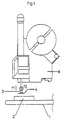
- the device shown schematically in Figure 1 for attaching adhesive labels to product packages contains a transport system 1, with the individual Goods packs 2 in a position below one linearly up and down in the direction of the double arrow f1 movable suction pad 3 are brought, each of which has an adhesive label 4 by means of suction air can be captured.
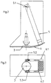
- This adhesive label 4 is according to Figure 2 to the suction pad 3 by means of a transfer element in the form of a Pass horizontal axis 5.1 pivotable arm 5, which has suction air openings on its underside, for example from an upstream one Printer 6 coming label to take over and to feed the suction pad 3.
- the transfer element 5 comprises two suction arms 5.2 and 5.3, at such a lateral distance from each other that they are in the vertical projection in particular circular suction pad 3 between them be able to record.
- the suction arms 5.2 and 5.3 of the transfer element 5 are guided in backdrop guides 6.1 and 6.2.
- Figure 2 shows the suction pad 3 in its uppermost position.
- the pivot radii of the lower ends of the two suction arms 5.2 and 5.3 are selected so that their two lower ends have a vertical distance indicated by the line a in their position below the suction plunger 3. This distance is used to ensure with the greatest possible certainty that the individual adhesive labels 4 can be brought into a position below the suction plunger 3 without interference.
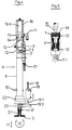
- the suction pad 3 is attached to the lower end of a hollow piston rod 7 ( Figure 4) carries at its upper end a piston 9 sealingly guided in a pneumatic cylinder 8.
- a first air connection 10 opens into the cylinder 8 below the piston 9.
- a second air connection 11 opens into the cylinder 8 above the piston 9.
- the piston 9 is by means of sliding rings 12 sealingly guided in the cylinder 8.
- a ring 14 made of ferromagnetic in the upper piston setting Material is opposite to the piston and thus the piston rod and the stamp even without air support in the upper dead or rest position.
- another piston rod section 15 connects forms part of a particularly pneumatic shock absorber unit 16 around the piston rod / piston unit 7/9 cushioning, especially when moving upwards.
- the hollow piston rod 7 is provided with a lateral air inlet opening 7.1.
- the one at that lower end of the hollow piston rod 7 attached suction plunger 3 has an axial bore 3.1, being between the lower end of the hollow piston rod 7 and the upper end of the Axial bore 3.1 is a check valve in the form of a ball 17, the seat of which is a Has not shown by-pass opening, whereby when closing the axial bore through the ball a minimal Air balance between the piston rod cavity 7 and the axial bore 3.1 takes place.
- a solenoid 19 arranged on which a return spring 18th attacks.
- This solenoid 19 is in vertical with one Equipped in the direction of the movable operating rod 19.1, to which a horizontal operating fork 19.2 is attached is, which engages around the lower end of the piston rod 7 and onto one attached to the lower end of the piston rod Support ring 20 can act.
- Hall effect sensors 21 are located on the side of the cylinder tube 8 attached, which serve as displacement sensors, the stroke of the piston 9 to different heights of the goods packs adjust and the stroke of the piston by regulation the air supply through the air connections 11 and 10 to control above and below the piston 9.
- Figure 6 shows a schematic representation of the Pneumatic cylinder 8 with the two air inlets 10 and 11 and the suction pad 3.
- the pneumatic Transfer element 5 is also only schematized shown.
- a power generator unit B comprises a drive motor M for driving a compressed air blower 30 and of a suction air blower 31.
- the compressed air blower 30 is via lines 32, 32.1 and 32.2 as well 3/2-way valves 34, 35 and connecting lines 34.1 or 35.1 connected to the air connections 11 and 10.
- the suction air blower 31 is via lines 33, 33.1 and 33.2 and the two 3/2-way valves 34, 35 and the further lines 34.1 and 35.1 the air connections 11 and 10 connected.
- the suction air blower 31 is via lines 33, 33.3 another 3/2-way valve 36 and the further Line 36.1 connected to the transfer element 5.
- In the further lines 34.1, 35.1 and 36.1 is preferably a filter block 37 with air filters 37.1, 37.2 and 37.3 interposed.
- Steps 1 to 8 control program control for actuation of the individual elements of the pneumatic control intended.
Landscapes
- Labeling Devices (AREA)
- Sheets, Magazines, And Separation Thereof (AREA)
- Adhesives Or Adhesive Processes (AREA)
Description
- Figur 1
- zeigt in schematischer Darstellung eine Seitenansicht der erfindungsgemäßen Vorrichtung mit vorgeschaltetem Drucker und einer Transportanlage zum Zuführen von Warenpackungen;
- Figur 2
- zeigt in schematischer Darstellung eine Seitenansicht einer Übergabeeinheit zur Übergabe von bedruckten Etiketten an die erfindungegemäße Vorrichtung;
- Figur 3
- zeigt eine Unteransicht der in Figur 2 dargestellten Vorrichtung;
- Figur 4
- zeigt teilweise in Schnitt und teilweise in der Seitenansicht die erfindungsgemäße Vorrichtung;
- Figur 5
- zeigt teilweise im Schnitt und teilweise als Seitenansicht in vergrößerter Darstellung die Kolbeneinheit der erfindungsgemäßen Vorrichtung;
- Figur 6
- zeigt in schematischer Darstellung die Pneumatikschaltung zur Beaufschlagung der erfindungsgemäßen Vorrichtung mit Druck- bzw. Saugluft.
Claims (4)
- Vorrichtung zum Anbringen von Haftetiketten auf Warenpackungen, enthaltend eine verschwenkbare Etikettenübergabeeinheit (5), mit der jeweils ein Etikett (4) mit geringfügigem Abstand in eine Etikettenübergabeposition unterhalb eines zwischen oberen und unteren Totlagen auf- und ab bewegbaren Übertragungsstempel förderbar ist, gekennzeichnet durch einen Pneumatik-Zylinder (8), der zwei unter Zwischenschaltung von programmgesteuerten 3/2 Wegeventilen wechselweise an eine Druckluftquelle und/oder Saugluftquelle anschließbare Lufteinlässe (10, 11) aufweist, und an dessen Außenseite Wegsensoren, insbesondere Hall-Effekt-Sensoren, zur Steuerung des erforderlichen Hubes des in dem Pneumatik-Zylinder (8) zwischen oberen und unteren Totlage geführten Kolbens (9) angeordnet sind, der an seiner Oberseite einen Permanentmagneten (13) trägt, dem in der oberen Totlage des Kolbens ein Gegenring (14) aus ferromagnetischem Material gegenüberliegt, und der am oberen Ende einer hohlen Kolbenstange (7) angebracht ist, die innerhalb des Pneumatik-Zylinders (8) eine seitliche Luftöffnung (7.1) aufweist und an ihrem unteren Ende außerhalb des Zylinders den als Saugstempel (3) ausgebildeten Übertragungsstempel trägt, dessen Saugkanal (3.1) axial an die hohle Kolbenstange (7) angeschlossen und gegenüber der hohlen Kolbenstange mittels eines Rückschlagventils (17) teilweise absperrbar ist, sowie
zum Absenken des Saugstempels (3) in die Etikettenibergabeposition durch eine Stelleinrichtung, welche ein parallel zur Zylinderachse auf- und abbewegbares Stellglied (19, 19.1, 19.2) aufweist, das mit einem außerhalb des Zylinders (8) an der Kolbenstangen-Saugstempel-Einheit befindlichen Anschlag (20) zusammenwirkt. - Vorrichtung nach Anspruch 1, dadurch gekennzeichnet, daß die Stelleinrichtung eine mittels eines Hubmagneten beeinflußbare, federbelastete Betätigungsstange (19.1) aufweist, an der eine horizontal ausgerichtete Betätigungsgabel (19.2) befestigt ist, die die Kolbenstange (7) oberhalb eines den Anschlag bildenden Stützringes (20) teilweise umgreift.
- Vorrichtung nach Anspruch 1, gekennzeichnet durch eine die Aufwärtsbewegung des Kolbens abbremsende Stoßdämpfereinheit (16).
- Vorrichtung nach Anspruch 3, dadurch gekennzeichnet, daß die Stoßdämpfereinheit (16) einen Pneumatik-Zylinder (16.1) aufweist, in der ein Kolben geführt ist, dessen Kolbenstange (15) oberhalb des Kolbens (9) endet.
Applications Claiming Priority (3)
| Application Number | Priority Date | Filing Date | Title |
|---|---|---|---|
| DE19531426 | 1995-08-26 | ||
| DE19531426A DE19531426A1 (de) | 1995-08-26 | 1995-08-26 | Vorrichtung zum Anbringen von Haftetiketten auf Warenpackungen |
| PCT/DE1996/001560 WO1997008055A1 (de) | 1995-08-26 | 1996-08-23 | Vorrichtung zum anbringen von haftetiketten auf warenpackungen |
Publications (2)
| Publication Number | Publication Date |
|---|---|
| EP0846074A1 EP0846074A1 (de) | 1998-06-10 |
| EP0846074B1 true EP0846074B1 (de) | 1999-11-03 |
Family
ID=7770460
Family Applications (1)
| Application Number | Title | Priority Date | Filing Date |
|---|---|---|---|
| EP96937982A Expired - Lifetime EP0846074B1 (de) | 1995-08-26 | 1996-08-23 | Vorrichtung zum anbringen von haftetiketten auf warenpackungen |
Country Status (10)
| Country | Link |
|---|---|
| US (1) | US6009926A (de) |
| EP (1) | EP0846074B1 (de) |
| AT (1) | ATE186264T1 (de) |
| AU (1) | AU1592797A (de) |
| DE (2) | DE19531426A1 (de) |
| DK (1) | DK0846074T3 (de) |
| ES (1) | ES2140909T3 (de) |
| PT (1) | PT846074E (de) |
| WO (1) | WO1997008055A1 (de) |
| ZA (1) | ZA967224B (de) |
Cited By (2)
| Publication number | Priority date | Publication date | Assignee | Title |
|---|---|---|---|---|
| DE10253843B3 (de) * | 2002-11-14 | 2004-05-06 | Bizerba Gmbh & Co. Kg | Etikettiervorrichtung für bewegte Gegenstände und Verfahren zur Etikettierung von bewegten Gegenständen |
| WO2025002810A1 (en) * | 2023-06-28 | 2025-01-02 | Evolabel Ab | Safety labelling system and method for operating a safety labelling system |
Families Citing this family (22)
| Publication number | Priority date | Publication date | Assignee | Title |
|---|---|---|---|---|
| AU7391700A (en) * | 1999-09-03 | 2001-04-10 | Forward Products Cc | Labelling apparatus |
| DE19952375A1 (de) | 1999-10-30 | 2001-05-10 | Espera Werke Gmbh | Vorrichtung zum Anbringen von Haftetiketten auf Warenpackungen |
| US6655436B1 (en) * | 2000-05-26 | 2003-12-02 | Gerber Technology, Inc. | Apparatus and method for labeling a layup of sheet material |
| US7229517B2 (en) * | 2000-06-06 | 2007-06-12 | Applied Extrusion Technologies, Inc. | Labeling apparatus and method employing radiation curable adhesive |
| US7074295B2 (en) * | 2000-06-06 | 2006-07-11 | Applied Extrusion Technologies, Inc. | Labelling apparatus and method for correcting visual adhesive defects |
| US6551439B1 (en) | 2000-06-06 | 2003-04-22 | Applied Extrusion Technologies, Inc. | Ultraviolet labeling apparatus and method |
| DK1289839T3 (da) | 2000-06-06 | 2004-09-13 | Applied Extrusion Technologies | Etiketteringsanordning og -fremgangsmåde, der anvender strålingshærdbar klæber |
| US6595259B2 (en) | 2001-01-09 | 2003-07-22 | Premark Fef L.L.C. | Vacuum actuated label applying wand |
| FR2825343B1 (fr) * | 2001-05-30 | 2003-11-28 | Ns Testut Sas | Etiqueteuse |
| ITBO20010360A1 (it) * | 2001-06-06 | 2002-12-06 | Gd Spa | Unita' per l'applicazione di tagliandi a pacchetti in macchine confezionatrici |
| US6792992B2 (en) * | 2002-03-15 | 2004-09-21 | Fmc Technologies Inc. | Label application device including a flow control element |
| WO2005017883A2 (en) * | 2003-08-15 | 2005-02-24 | Integrated Healthcare Systems, Inc. | Method and apparatus for delivering barcode-to-dose labels |
| US7294216B2 (en) * | 2004-04-09 | 2007-11-13 | Cobra Placement Systems Llc | Liner driven component transfer systems and methods |
| EP1819597A2 (de) * | 2004-09-03 | 2007-08-22 | FMC Technologies, Inc. | Etikettiergerät |
| EP2695818A1 (de) * | 2012-08-10 | 2014-02-12 | Marel Limited | Etikettiervorrichtung zum Etikettieren von Objekten, insbesondere von sich bewegenden Objekten |
| WO2014179557A1 (en) * | 2013-05-01 | 2014-11-06 | Intelligrated Headquarters, Llc | Device for stabilizing a pallet |
| DE102014119391C5 (de) * | 2014-12-22 | 2019-02-28 | Espera-Werke Gmbh | Vorrichtung und Verfahren zum Etikettieren von einzelnen Packungen |
| DE102015106647A1 (de) * | 2015-04-29 | 2016-11-03 | Espera-Werke Gmbh | Vorrichtung zum Etikettieren von einzelnen Produkten |
| KR101919614B1 (ko) * | 2016-12-09 | 2018-11-16 | (주)솔로몬시스템 | 환자 관리 보조용 로봇 |
| ES2880435T3 (es) * | 2017-12-08 | 2021-11-24 | Multivac Marking & Inspection | Etiquetadora con conjunto deslizante |
| CN110589149B (zh) * | 2019-10-08 | 2024-07-19 | 深圳市艺盛科五金电子有限公司 | 一种smt投首自动化设备 |
| CN117383026B (zh) * | 2023-12-11 | 2024-04-16 | 珠海格力智能装备有限公司 | 一种基于多连杆以及同步带传送的旋转贴标结构 |
Family Cites Families (8)
| Publication number | Priority date | Publication date | Assignee | Title |
|---|---|---|---|---|
| US4124436A (en) * | 1977-05-02 | 1978-11-07 | Hi-Speed Checkweigher Co., Inc. | Cylinder label applier |
| US4255220A (en) * | 1979-02-02 | 1981-03-10 | Label-Aire Inc. | Method for supplying a label to an article surface |
| US4475978A (en) * | 1981-05-26 | 1984-10-09 | Label-Aire Inc. | Label applicator and method for labeling the forward faces of articles |
| EP0090631A3 (de) * | 1982-03-26 | 1984-10-24 | Berkel Limited | Vorrichtung zum Anbringen von Etiketten |
| US4561921A (en) * | 1983-05-05 | 1985-12-31 | Hobart Corporation | Label applicator and method of label application |
| US4595447A (en) * | 1984-12-10 | 1986-06-17 | Hi-Speed Checkweigher Co., Inc. | Article labeling machine |
| DE9107898U1 (de) * | 1991-06-27 | 1991-08-14 | SRD Maschinenbau GmbH, 4901 Hiddenhausen | Vorrichtung zum Aufbringen von selbstklebenden Etiketten auf Gegenstände |
| CA2147535A1 (en) * | 1994-04-29 | 1995-10-30 | Albert Wurz | Label applicator for articles of varying dimensions detected and processed by sensors and a cpu |
-
1995
- 1995-08-26 DE DE19531426A patent/DE19531426A1/de not_active Withdrawn
-
1996
- 1996-08-23 DE DE59603586T patent/DE59603586D1/de not_active Expired - Fee Related
- 1996-08-23 PT PT96937982T patent/PT846074E/pt unknown
- 1996-08-23 AT AT96937982T patent/ATE186264T1/de not_active IP Right Cessation
- 1996-08-23 AU AU15927/97A patent/AU1592797A/en not_active Abandoned
- 1996-08-23 ES ES96937982T patent/ES2140909T3/es not_active Expired - Lifetime
- 1996-08-23 DK DK96937982T patent/DK0846074T3/da active
- 1996-08-23 WO PCT/DE1996/001560 patent/WO1997008055A1/de not_active Ceased
- 1996-08-23 US US09/029,220 patent/US6009926A/en not_active Expired - Fee Related
- 1996-08-23 EP EP96937982A patent/EP0846074B1/de not_active Expired - Lifetime
- 1996-08-26 ZA ZA967224A patent/ZA967224B/xx unknown
Cited By (4)
| Publication number | Priority date | Publication date | Assignee | Title |
|---|---|---|---|---|
| DE10253843B3 (de) * | 2002-11-14 | 2004-05-06 | Bizerba Gmbh & Co. Kg | Etikettiervorrichtung für bewegte Gegenstände und Verfahren zur Etikettierung von bewegten Gegenständen |
| WO2004043786A1 (de) | 2002-11-14 | 2004-05-27 | Bizerba Gmbh & Co. Kg | Etikettiervorrichtung für bewegte gegenstände und verfahren zur etikettierung von bewegten gegenständen |
| US7392833B2 (en) | 2002-11-14 | 2008-07-01 | Bizerba Gmbh & Co. Kg | Labeling device for moved objects and method of labeling moved objects |
| WO2025002810A1 (en) * | 2023-06-28 | 2025-01-02 | Evolabel Ab | Safety labelling system and method for operating a safety labelling system |
Also Published As
| Publication number | Publication date |
|---|---|
| DE19531426A1 (de) | 1997-02-27 |
| AU1592797A (en) | 1997-03-19 |
| DK0846074T3 (da) | 2000-05-08 |
| DE59603586D1 (de) | 1999-12-09 |
| ES2140909T3 (es) | 2000-03-01 |
| EP0846074A1 (de) | 1998-06-10 |
| PT846074E (pt) | 2000-04-28 |
| US6009926A (en) | 2000-01-04 |
| ZA967224B (en) | 1997-03-03 |
| WO1997008055A1 (de) | 1997-03-06 |
| ATE186264T1 (de) | 1999-11-15 |
Similar Documents
| Publication | Publication Date | Title |
|---|---|---|
| WO1997008055A1 (de) | Vorrichtung zum anbringen von haftetiketten auf warenpackungen | |
| DE2447983C3 (de) | Vorrichtung zum Aufstapeln und Zählen von gefalteten Kartonzuschnitten | |
| WO1989000965A1 (fr) | Elevateur aspirateur pour convoyeur | |
| DE3873650T2 (de) | Antriebsvorrichtung und verfahren fuer eine doppelbalgabgabeeinheit. | |
| DE4428242A1 (de) | Verfahren und Anlage zum automatischen Etikettieren | |
| DE4209238A1 (de) | Transporteinrichtung | |
| DE1960656B2 (de) | Verfahren und vorrichtung zum ueberfuehren von empfindlichen, unsymmetrisch ausgebildeten packungen | |
| DE1611830A1 (de) | Verpackungsmaschine | |
| DE4339839A1 (de) | Abstapelvorrichtung für Bleche | |
| EP1574335A1 (de) | Vorrichtung zum Zuführen und Wegführen von Objekten zu bzw. von einer Maschine zum Dekorieren derselben | |
| DE2802475C3 (de) | Saugluftsteuerung für Bogenanlegemaschinen | |
| DE68902412T2 (de) | Hebevorrichtung mit sauggreifen. | |
| DE2218682A1 (de) | Vorrichtung zum Entstapeln von Blechfolien und/oder Blechtafeln | |
| DE3730063A1 (de) | Faltschachtelfoerdervorrichtung | |
| DE3234910C2 (de) | ||
| DE3302873C2 (de) | ||
| WO2007028551A1 (de) | Vorrichtung zum führen von gegenständen in einer förderstrecke | |
| DE3818793A1 (de) | Vorrichtung zum ausrichten und oeffnen flachliegender kunststoffsaecke | |
| EP0247024A1 (de) | Vorrichtung zum sanften Absetzen von Einzelstücken, insbesondere Steine auf eine Unterlage | |
| DE1058432B (de) | Geraet zur Entnahme von steifen Folien, z. B. bedruckten Blechen, aus einem stetig umlaufenden Foerderrost | |
| DE2711949A1 (de) | Automatische kartonverschliessmaschine | |
| EP0154159A1 (de) | Kranladegeschirr | |
| DE102008016597B4 (de) | Bogenanleger mit einem Bogentrenner | |
| DE7016336U (de) | Vorrichtung zum trennen von textilstuecken. | |
| DE614257C (de) | Bogenablegevorrichtung |
Legal Events
| Date | Code | Title | Description |
|---|---|---|---|
| PUAI | Public reference made under article 153(3) epc to a published international application that has entered the european phase |
Free format text: ORIGINAL CODE: 0009012 |
|
| 17P | Request for examination filed |
Effective date: 19980211 |
|
| AK | Designated contracting states |
Kind code of ref document: A1 Designated state(s): AT BE CH DE DK ES FR GB GR IE IT LI LU MC NL PT SE |
|
| RBV | Designated contracting states (corrected) |
Designated state(s): AT BE CH DE DK ES FR GB GR IE IT LI LU MC NL PT SE |
|
| 17Q | First examination report despatched |
Effective date: 19980722 |
|
| GRAG | Despatch of communication of intention to grant |
Free format text: ORIGINAL CODE: EPIDOS AGRA |
|
| GRAG | Despatch of communication of intention to grant |
Free format text: ORIGINAL CODE: EPIDOS AGRA |
|
| GRAH | Despatch of communication of intention to grant a patent |
Free format text: ORIGINAL CODE: EPIDOS IGRA |
|
| GRAH | Despatch of communication of intention to grant a patent |
Free format text: ORIGINAL CODE: EPIDOS IGRA |
|
| GRAA | (expected) grant |
Free format text: ORIGINAL CODE: 0009210 |
|
| AK | Designated contracting states |
Kind code of ref document: B1 Designated state(s): AT BE CH DE DK ES FR GB GR IE IT LI LU MC NL PT SE |
|
| PG25 | Lapsed in a contracting state [announced via postgrant information from national office to epo] |
Ref country code: GR Free format text: LAPSE BECAUSE OF NON-PAYMENT OF DUE FEES Effective date: 19991103 |
|
| REF | Corresponds to: |
Ref document number: 186264 Country of ref document: AT Date of ref document: 19991115 Kind code of ref document: T |
|
| REG | Reference to a national code |
Ref country code: CH Ref legal event code: EP |
|
| REF | Corresponds to: |
Ref document number: 59603586 Country of ref document: DE Date of ref document: 19991209 |
|
| ITF | It: translation for a ep patent filed | ||
| REG | Reference to a national code |
Ref country code: IE Ref legal event code: FG4D Free format text: GERMAN |
|
| REG | Reference to a national code |
Ref country code: CH Ref legal event code: NV Representative=s name: A. BRAUN, BRAUN, HERITIER, ESCHMANN AG PATENTANWAE |
|
| GBT | Gb: translation of ep patent filed (gb section 77(6)(a)/1977) |
Effective date: 20000124 |
|
| REG | Reference to a national code |
Ref country code: ES Ref legal event code: FG2A Ref document number: 2140909 Country of ref document: ES Kind code of ref document: T3 |
|
| ET | Fr: translation filed | ||
| REG | Reference to a national code |
Ref country code: PT Ref legal event code: SC4A Free format text: AVAILABILITY OF NATIONAL TRANSLATION Effective date: 20000201 |
|
| REG | Reference to a national code |
Ref country code: DK Ref legal event code: T3 |
|
| PGFP | Annual fee paid to national office [announced via postgrant information from national office to epo] |
Ref country code: GB Payment date: 20000727 Year of fee payment: 5 |
|
| PGFP | Annual fee paid to national office [announced via postgrant information from national office to epo] |
Ref country code: FR Payment date: 20000817 Year of fee payment: 5 |
|
| PGFP | Annual fee paid to national office [announced via postgrant information from national office to epo] |
Ref country code: PT Payment date: 20000822 Year of fee payment: 5 Ref country code: ES Payment date: 20000822 Year of fee payment: 5 |
|
| PGFP | Annual fee paid to national office [announced via postgrant information from national office to epo] |
Ref country code: NL Payment date: 20000824 Year of fee payment: 5 Ref country code: CH Payment date: 20000824 Year of fee payment: 5 Ref country code: BE Payment date: 20000824 Year of fee payment: 5 Ref country code: AT Payment date: 20000824 Year of fee payment: 5 |
|
| PGFP | Annual fee paid to national office [announced via postgrant information from national office to epo] |
Ref country code: SE Payment date: 20000825 Year of fee payment: 5 |
|
| PGFP | Annual fee paid to national office [announced via postgrant information from national office to epo] |
Ref country code: DK Payment date: 20000828 Year of fee payment: 5 |
|
| PGFP | Annual fee paid to national office [announced via postgrant information from national office to epo] |
Ref country code: IE Payment date: 20000829 Year of fee payment: 5 |
|
| PGFP | Annual fee paid to national office [announced via postgrant information from national office to epo] |
Ref country code: LU Payment date: 20000830 Year of fee payment: 5 |
|
| PG25 | Lapsed in a contracting state [announced via postgrant information from national office to epo] |
Ref country code: MC Free format text: THE PATENT HAS BEEN ANNULLED BY A DECISION OF A NATIONAL AUTHORITY Effective date: 20000831 |
|
| PLBE | No opposition filed within time limit |
Free format text: ORIGINAL CODE: 0009261 |
|
| STAA | Information on the status of an ep patent application or granted ep patent |
Free format text: STATUS: NO OPPOSITION FILED WITHIN TIME LIMIT |
|
| 26N | No opposition filed | ||
| REG | Reference to a national code |
Ref country code: IE Ref legal event code: FD4D |
|
| REG | Reference to a national code |
Ref country code: IE Ref legal event code: FD4D Ref document number: ERRATA: Incorrectly Country of ref document: IE |
|
| PG25 | Lapsed in a contracting state [announced via postgrant information from national office to epo] |
Ref country code: LU Free format text: LAPSE BECAUSE OF NON-PAYMENT OF DUE FEES Effective date: 20010823 Ref country code: IE Free format text: LAPSE BECAUSE OF NON-PAYMENT OF DUE FEES Effective date: 20010823 Ref country code: GB Free format text: LAPSE BECAUSE OF NON-PAYMENT OF DUE FEES Effective date: 20010823 Ref country code: DK Free format text: LAPSE BECAUSE OF NON-PAYMENT OF DUE FEES Effective date: 20010823 Ref country code: AT Free format text: LAPSE BECAUSE OF NON-PAYMENT OF DUE FEES Effective date: 20010823 |
|
| PG25 | Lapsed in a contracting state [announced via postgrant information from national office to epo] |
Ref country code: SE Free format text: LAPSE BECAUSE OF NON-PAYMENT OF DUE FEES Effective date: 20010824 Ref country code: ES Free format text: LAPSE BECAUSE OF NON-PAYMENT OF DUE FEES Effective date: 20010824 |
|
| PG25 | Lapsed in a contracting state [announced via postgrant information from national office to epo] |
Ref country code: LI Free format text: LAPSE BECAUSE OF NON-PAYMENT OF DUE FEES Effective date: 20010831 Ref country code: CH Free format text: LAPSE BECAUSE OF NON-PAYMENT OF DUE FEES Effective date: 20010831 Ref country code: BE Free format text: LAPSE BECAUSE OF NON-PAYMENT OF DUE FEES Effective date: 20010831 |
|
| PGFP | Annual fee paid to national office [announced via postgrant information from national office to epo] |
Ref country code: DE Payment date: 20010928 Year of fee payment: 6 |
|
| BERE | Be: lapsed |
Owner name: ESPERA-WERKE G.M.B.H. Effective date: 20010831 |
|
| PG25 | Lapsed in a contracting state [announced via postgrant information from national office to epo] |
Ref country code: PT Free format text: LAPSE BECAUSE OF NON-PAYMENT OF DUE FEES Effective date: 20020228 |
|
| PG25 | Lapsed in a contracting state [announced via postgrant information from national office to epo] |
Ref country code: NL Free format text: LAPSE BECAUSE OF NON-PAYMENT OF DUE FEES Effective date: 20020301 |
|
| EUG | Se: european patent has lapsed |
Ref document number: 96937982.5 |
|
| REG | Reference to a national code |
Ref country code: CH Ref legal event code: PL |
|
| GBPC | Gb: european patent ceased through non-payment of renewal fee |
Effective date: 20010823 |
|
| REG | Reference to a national code |
Ref country code: DK Ref legal event code: EBP |
|
| PG25 | Lapsed in a contracting state [announced via postgrant information from national office to epo] |
Ref country code: FR Free format text: LAPSE BECAUSE OF NON-PAYMENT OF DUE FEES Effective date: 20020430 |
|
| NLV4 | Nl: lapsed or anulled due to non-payment of the annual fee |
Effective date: 20020301 |
|
| REG | Reference to a national code |
Ref country code: IE Ref legal event code: MM4A |
|
| REG | Reference to a national code |
Ref country code: FR Ref legal event code: ST |
|
| REG | Reference to a national code |
Ref country code: PT Ref legal event code: MM4A Free format text: LAPSE DUE TO NON-PAYMENT OF FEES Effective date: 20020228 |
|
| PG25 | Lapsed in a contracting state [announced via postgrant information from national office to epo] |
Ref country code: DE Free format text: LAPSE BECAUSE OF NON-PAYMENT OF DUE FEES Effective date: 20030301 |
|
| REG | Reference to a national code |
Ref country code: ES Ref legal event code: FD2A Effective date: 20020911 |
|
| PG25 | Lapsed in a contracting state [announced via postgrant information from national office to epo] |
Ref country code: IT Free format text: LAPSE BECAUSE OF NON-PAYMENT OF DUE FEES Effective date: 20050823 |