EP0807536B1 - Mechanismus zum Auswerfen von Bogenstapeln für Blattsortiergerät - Google Patents
Mechanismus zum Auswerfen von Bogenstapeln für Blattsortiergerät Download PDFInfo
- Publication number
- EP0807536B1 EP0807536B1 EP97107736A EP97107736A EP0807536B1 EP 0807536 B1 EP0807536 B1 EP 0807536B1 EP 97107736 A EP97107736 A EP 97107736A EP 97107736 A EP97107736 A EP 97107736A EP 0807536 B1 EP0807536 B1 EP 0807536B1
- Authority
- EP
- European Patent Office
- Prior art keywords
- sheet
- bin
- sheets
- sheet stack
- bins
- Prior art date
- Legal status (The legal status is an assumption and is not a legal conclusion. Google has not performed a legal analysis and makes no representation as to the accuracy of the status listed.)
- Expired - Lifetime
Links
Images


Classifications
-
- B—PERFORMING OPERATIONS; TRANSPORTING
- B42—BOOKBINDING; ALBUMS; FILES; SPECIAL PRINTED MATTER
- B42C—BOOKBINDING
- B42C1/00—Collating or gathering sheets combined with processes for permanently attaching together sheets or signatures or for interposing inserts
- B42C1/12—Machines for both collating or gathering and permanently attaching together the sheets or signatures
- B42C1/125—Sheet sorters combined with binding devices
Definitions
- This invention relates to a sheet stack ejector mechanism for a sheet sorter, and more particularly to a sheet stack ejector mechanism for use in a sheet sorter, which is provided with a plurality of bins each of which receives a plurality of sheets discharged from an image recording apparatus such as a printer, a copier or the like and forms thereon a stack of sheets, in order to eject the sheet stack on each bin toward a post handling mechanism such as a punch, a stapler or the like which is movable up and down along the array of the sheet inlet ends of the bins.
- a post handling mechanism such as a punch, a stapler or the like which is movable up and down along the array of the sheet inlet ends of the bins.
- a sheet sorter in which a plurality of recorded sheets discharged from an image recording apparatus such as a printer, a copier or the like are distributed to a plurality of bins or sort trays in sequence to form a stack of sheets on each bin by a sheet distributor called an indexer and when the number of the sheets stacked on each of the bins reaches a predetermined value, the sheet stack on each of the bins is stapled by a stapler which is movable up and down along the array of the sheet inlet ends of the bins and in a horizontal direction along the edge of each bin.
- each bin is arranged to be movable toward the stapler and the selected bin is moved toward the stapler to bring the sheet stack thereon to the stapler, or a sheet stack ejector is provided for each of the bins.
- each of the bins is movable toward the stapler, provision to prevent interference between the bin and the stapler must be made. Further either of the conventional structures complicates the structure of the sorter and its drive system.
- each bin is provided with an ejector, it becomes difficult for the ejector to eject the sheet stack on the bin when the bin is deflected or deformed.
- the primary object of the present invention is to provide a sheet stack ejector mechanism for a sheet sorter which is simple in structure.
- Another object of the present invention is to provide a sheet stack ejector mechanism for a sheet sorter in which it is not necessary to provide an ejector for each of the bins.
- Still another object of the present invention is to provide a sheet stack ejector mechanism for a sheet sorter which can eject the sheet stack on each bin even if the bin is deformed or deflected.
- the sheet stack ejector mechanism in accordance with the present invention is for use in a sheet sorter, comprising a plurality of bins arranged in a vertical direction each of which receives a plurality of sheets discharged from an image recording apparatus and forms thereon a stack of sheets, a sheet transfer means which transfers the sheets discharged from the image recording apparatus, an indexer which receives the sheets from the sheet transfer means and is movable up and down along the array of sheet inlet ends of the bins to distribute the sheets to the respective bins through the sheet inlet ends thereof, and a post handling means which is movable up and down along the array of the sheet inlet ends of the bins and carries out a predetermined post handling on the stack of sheets on each of the bins, in order to eject the stack of sheets on each of the bins beyond the sheet inlet end of the bin by a predetermined length, thereby giving the post handling means access to the stack of sheets.
- the sheet stack ejector mechanism of the present invention comprises a guide rail which extends in a vertical direction through the bins, and a sheet stack ejector member which is mounted on the guide rail to be movable up and down along the guide rail and is adapted to eject the stacks of sheets on the respective bins one by one toward the post handling means.
- the post handling means may comprise a stapler which binds the stack of sheets.
- the guide rail be movable toward the sheet inlet ends of the bins and the sheet stack ejector member be projected from the guide rail toward the sheet inlet ends by a distance not smaller than said predetermined length.
- Said guide rail may double as a stopper which abuts against the leading edge of the sheet fed into the bin by the indexer and stops the sheet.
- the sheet stack ejector member be engaged with a surface of each bin and ejects the stack of sheets on the bin toward the post handling means under the guidance of the surface of the bin, and at the same time the sheet stack ejector member be movable up and down along the guide rail in a position where the sheet stack ejector member is disengaged from the surface of the bin.
- the sheet stack ejector member ejects the stack of sheets on the bin toward the post handling means held between adjacent bins.
- the sheet stack ejector may be provided with a stopper which abuts against the leading edge of the sheet fed into the bin by the indexer and stops the sheet separately from said guide rail.
- the sheet stack ejector mechanism of this invention since the sheet stack ejector adapted to eject the stacks of sheets on the respective bins one by one toward the post handling means is mounted for up-and-down movement on the guide rail which extends through the bins, the bins may be kept stationary and it is not necessary to provide a sheet stack ejector for each bin, whereby the sheet sorter and its drive system may be very simple in structure.
- the guide rail when the guide rail is movable toward the sheet inlet end of the bin, the guide rail may be arranged to function also as a stopper of the sheet and/or a member for lining up the sheets.
- the sheet stack ejector member is moved upward or downward to its retracted position when the guide rail functions as a stopper of the sheet and/or a member for lining up the sheets.
- the sheet stack ejector member When the sheet stack ejector member is arranged to eject the stack of sheets on the selected bin toward the post handling means while moving toward the post handling means under the guidance of the surfaces of the adjacent bins held therebetween, the sheet stack ejector member can be moved along the bin even if the bins have been deformed or deflected, whereby the stack of sheets can be surely ejected.
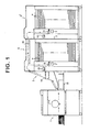
- a sheet sorter S comprises a plurality of (e.g., fifty) bins (sort trays) 4 which are disposed in fixed positions in a frame 3 at predetermined intervals in the vertical direction and receive a plurality of recorded sheets 2 ( Figure 3) discharged from an image recording apparatus 1 such as a printer to form a stack of the sheets 2 on each bin 4, a sheet transfer means 5 which transfers the sheets 2 discharged from the image recording apparatus 1 toward the bins 4, an indexer 6 which is movable up and down along the array of the sheet inlet ends 4a of the bins 4 and distributes the sheets 2 transferred by the sheet transfer means 5 to the respective bins 4, and a stapler 7 which is movable up and down along the array of the sheet inlet ends 4a of the bins 4 and in a horizontal direction along the edge of the sheet inlet end 4a of each bin.
- an image recording apparatus 1 such as a printer to form a stack of the sheets 2 on each bin 4
- a sheet transfer means 5 which transfers the sheets 2 discharged from the image
- the image recording apparatus 1 is a printer, especially a stencil printer
- a number of sheets can be printed in a short time and recorded sheets 2 carrying thereon wet ink are discharged at a high rate.
- the sheet transfer means 5 comprises perforated conveyor belts 9 and 10 which convey the sheets 2 with the back side of the sheets 2 attracted against the belts 9 and 10 under vacuum applied by blowers 8 and a fan 11 which presses the sheets 2 against the belt 10 under an air pressure as clearly shown in Figure 2.
- the sheet sorter S is arranged so that a plurality of slaves S' having the same structure as the main sheet sorter S can be connected to the sheet sorter S as shown in Figure 1 in order to increase the total number of the bins 4.
- the slaves S' are connected to the main sheet sorter S on the side remote from the image recording apparatus 1.
- a sheet conveyor 12 is demountably mounted on an upper portion of the main sheet sorter S and the sheets 2 in the main sheet sorter S are transferred to the slaves S' by the sheet conveyor 12 when the slaves S' are connected to the main sheet sorter S.
- the image recording apparatus 1 is provided with a sheet tray 13 on which the discharged sheets 2 are stacked when sorting of the sheets 2 is not necessary. Further a control panel 14 and an exterior electric stapler 15 are mounted on the outer surface of the sheet sorter S.
- the stapler 7 waits beside the path of the indexer 6 while the indexer 6 is moving up and down.
- the position in which the stapler 7 waits is such that the indexer 6 is brought into alignment with the stapler 7 in a horizontal direction when the indexer 6 is moved to a position where it can distribute a sheet 2 to the lowermost bin 4.
- side edges of the sheets 2 placed on each bin 4 are lined up along a side edge reference surface L1 defined by the inner surface of a sheet stack take-out door 18 which is rotatable about a pin 18a.
- a pair of side lineup rods 21a and 21b which push the sheet 2 in the direction of width of the sheet 2 and bring the side edge of the sheet 2 into abutment against the side edge reference surface L1
- a stopper member 22 of a resilient material such as rubber band against which the leading edge of the sheet 2 is brought into abutment when the leading edge is released into the bin 4 at a high speed from the indexer 6, thereby gently stopping the sheet 2, and a guide rail 26 along which a sheet stack ejector 25 (to be described later) is moved up and down.
- the side lineup rods 21a and 21b and the stopper member 22 are moved respectively along slots 23a, 23b and 24.
- the stopper member 22 is moved along the slot 24 left and right as seen in Figure 3 by a distance according to the size of the sheets 2 to be released from the indexer 6.
- the guide rail 26 doubles as a lineup rod which pushes the leading edge of the sheet 2 to move the sheet 2 toward the sheet inlet end 4a of the bin 4 so that the trailing edge of the sheet 2 is brought into abutment against a trailing edge reference surface L2.
- the guide rail 26 is provided with a flat vertical surface 26a facing toward the sheet inlet end 4a of the bin 4.
- the guide rail 26 is movable left and right as seen in Figure 3 in an opening 27 formed in the bin 4.
- the side lineup rods 21a and 21b are movable at angles to the direction in which the sheet 2 is fed into the bin 4 so that they are simultaneously moved toward and away from both the reference surfaces L1 and L2 and can act on various sizes of the sheets 2. Further the angle at which the path of the side lineup rod 21b, which is at a larger distance from the trailing edge reference surface L2, is inclined to the feeding direction of the sheet 2 is smaller than that of the other side lineup rod 21a, and accordingly as the rods 21a and 21b are moved toward the side edge of the sheet 2, the distance between the rods 21a and 21b becomes smaller.
- the sheet stacks 20 ( Figure 6) on the respective bins 4 are ejected, in sequence for stapling operation, beyond the trailing edge reference surface L2 into the path along which the indexer 6 is moved up and down.
- a sheet stack ejector 25 is provided.
- the sheet stack ejector 25 is movable in the opening 27 of the respective bins 4 along the guide rail 26 which vertically extends through the bins 4.
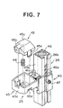
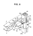
- the guide rail 26 is in the form of a hollow post rectangular in cross-section and the sheet stack ejector 25 comprises a base 40 which is mounted on the guide rail 26 to be movable up and down along the outer surface of the guide rail 26, a body portion 43 which is resiliently supported on the base 40 to be movable up and down with respect to the base 40 by way of a pin 41 and a pair of coiled springs 42 and is in the form a box open upward, and a movable portion 45 which is incorporated in the body portion 43 to be movable up and down with respect to the body portion 43.
- the movable portion 45 is urged upward by a coiled spring 44 compressed between the body portion 43 and the movable portion 45.
- the coiled spring 44 is stronger than the coiled springs 42.
- a screw rod 46 extends through the guide rail 26 to be rotatable about its longitudinal axis.
- the guide rail 26 is provided with a slot 26b which is formed in one side wall of the guide rail 26 to extend in the longitudinal direction thereof as shown in Figure 7.
- a pin 47 fixed to the base 40 of the sheet stack ejector 25 extends through the slot 26b of the guide rail 26 and is in mesh with the thread 46a of the screw rod 46. Accordingly when the screw rod 46 is rotated in one direction, the sheet stack ejector 25 is moved upward along the guide rail 26 and when the screw rod 46 is rotated in the other direction, the sheet stack ejector 25 is moved downward along the guide rail 26.
- the opening 27 of each bin 4 is surrounded by an elevated edge portion 46 having a flat and horizontal top surface.
- the top surface of the elevated edge portion 46 of the opening 27 is elevated from the bottom of the bin 4 by a predetermined amount and the sheets 2 fed to the bin 4 rest on the top surface of the elevated edge portion 46 of the opening 27.
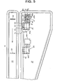
- the part of the elevated edge portion of the opening 27 extending along the path of the sheet stack ejector 25, along which the sheet stack ejector 25 is moved when ejecting the sheet stack 20, comprises an engagement portion 4b which projects into the path of the sheet stack ejector 25 and linearly extends in the direction of the path so that the sheet stack ejector 25 is moved toward the sheet inlet end 4a of the bin 4 in engagement with the engagement portion4b, a retracted portion 4d which is positioned away from the path of the sheet stack ejector 25 and an oblique intermediate portion 4c connecting the engagement portion 4b and the retracted portion 4d.
- the sheet stack ejector 25 When the guide rail 26 is in the rightmost position shown by the solid line in Figure 5, the sheet stack ejector 25 is opposed to the retracted portion 4d of the elevated edge portion and accordingly is free from the elevated edge portion so that the sheet stack ejector 25 can be moved up and down along the guide rail 26.
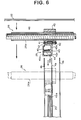
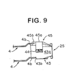
- the movable portion 45 of the sheet stack ejector 25 has a flat top surface 45a, an inclined surface 45b which is inclined downward from the top surface 45a and faces toward the sheet inlet end 4a of the bin 4, and a pair of resilient engagement pieces 45c (only one of them is shown) which are engaged with engagement portions 43d of the body portion 43 to be described later to keep the movable portion 45 on the body portion 43.
- the body portion 43 of the sheet stack ejector 25 has a flat and vertical abutment surface 43a which faces toward the sheet inlet end 4a of the bin 4 and is brought into abutment against the sheet stack 20 when ejecting the same, a flat and horizontal engagement surface 43b facing downward, and an inclined guide surface 43c ( Figure 6) which is inclined upward from the front (as seen in the direction of travel of the sheet stack ejector 25 when ejecting the sheet stack 20) edge of the engagement surface 43b.
- the body portion 43 is further provided with a pair of engagement portions 43d ( Figure 7) which are engaged with the engagement pieces 45c of the movable portion 45 when the movable portion 45 is forced into the body portion 43 from above, thereby keeping the movable portion 45 on the body portion 43 with the coiled spring 44 compressed therebetween.
- the movable portion 45 is supported for up and down movement on the body portion 43 while urged upward by the coiled spring 44.
- the sheet stack 20 on one of the bins 4 When the sheet stack 20 on one of the bins 4 is to be stapled, the sheet stack 20 on the bin 4 must be ejected from the sheet inlet end 4a of the bin 4 by a predetermined length, and accordingly the abutment surface 43a of the body portion 43 of the sheet stack ejector 25 is positioned at a distance not smaller than the predetermined length from the vertical surface 26a of the guide rail 26.
- the guide rail 26 brings the trailing edges of the sheets 2 into alignment with each other on a trailing edge reference surface L2
- the sheet stack ejector 25 is moved upward or downward along the guide rail 26 to a position where the sheet stack ejector 25 does not interfere with the lineup operation of the guide rod 26.
- the sheet stack ejector 25 When ejecting the sheet stack 20 on a selected bin 4, the sheet stack ejector 25 is first moved along the guide rail 26 to a predetermined position suitable for ejecting the sheet stack 20 on the bin 4 and the guide rail 26 is moved toward the sheet inlet end 4a of the bin 4 from the position shown in Figures 5, 6 and 8.
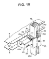
- the inclined guide surface 43c of the body portion 43 of the sheet stack ejector 25 comes to be engaged with the upper surface of the intermediate portion 4c of the elevated edge portion of the opening 27 of the selected bin 4 and at the same time the inclined surface 45b of the movable portion 45 comes to be engaged with the lower surface of the intermediate portion 4c of the elevated edge portion of the opening 27 of the bin 4 just above the selected bin 4.
- the level of the sheet stack ejector 25 is adjusted by resiliency of the springs 42 and the engagement surface 43b of the body portion 43 comes to be resiliently engaged with the upper surface of the engagement portion 4b of the elevated edge portion of the selected bin 4 while the top surface 45a of the movable portion 45 comes to be resiliently engaged with the lower surface of the engagement portion 4b of the elevated edge portion of the bin 4 just above the selected bin 4 under the strong resilient force of the spring 44 as shown in Figures 10 and 11.
- the sheet stack ejector 25 ejects the sheet stack 20 on the selected bin 4 toward the stapler 7 while moving toward the stapler 7 under the guidance of the surfaces of the engagement portions 4b of the adjacent bins 4 held therebetween.
- the sheet stack ejector 25 can be moved along the deflected or deformed bin 4, whereby the sheet stack 20 can be surely ejected.
- the guide rail 26 doubles as a lineup rod for bringing the trailing edges of the sheets 2 into alignment with each other on the reference surface L2 and the stopper member 22 is provided separately from the guide rail 26, the guide rail 26 may be arranged to further double as the stopper member.
- a lineup rod may be provided in the position of the stopper member 22 to double as the stopper member.
- the lineup rod be provided with a resilient member on the surface facing the sheet inlet end 4a of the bin 4 in order to gently stop the sheets 2.
- a resilient stopper member similar to the stopper member 22 employed in this embodiment may be provided at a distance from the lineup rod toward the sheet inlet end 4a of the bin 4 instead of providing a resilient member on the lineup rod.
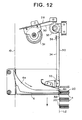
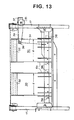
- Figures 12 and 13 show a member for defining the reference surface L2.
- the indexer 6 has a plurality of sheet guide ribs 6a and is driven by endless belts 17 (Figure 13) up and down along the array of the sheet inlet ends 4a of the bins 4.
- the trailing edge reference surface L2 extends along the array of the sheet inlet ends 4a of the bins 4 and is defined by a pair of strip-like spring members 30 each having a width d as shown in Figures 4 and 13.
- the spring member 30 is in a continuous length and fed out from a roll in a casing 31 ( Figure 12) which is fixed to the frame 3 by way of a bracket 28.
- the part of the spring member 30 extending outside the casing 31 is passed around a reel 32 and extends right downward.
- the leading end of the spring member 30 is fixed to a fixing member 33 which is provided just above the sheet discharge port 6b of the indexer 6 close thereto.
- the spring members 30 are long fed out from the casing 31 as the indexer 6 moves downward and close the sheet inlet ends 4a of the bins 4 which are above the sheet discharge end 6b of the indexer 6, thereby forming the trailing edge reference surface L2. As the indexer 6 moves upward the spring members 30 are taken up into the casing 31.
- a second strip-like spring member 34 which is smaller than the spring member 30 in width is employed to reinforce the spring member 30, thereby holding flat the spring member 30. That is, the second spring member 34 is in a continuous length and fed out from a roll in a casing 35 which is fixed to the frame 3 by way of a bracket 37 so that the longitudinal axis of the casing 35 is substantially perpendicular to that of the casing 31 of the spring member 30.
- the part of the second spring member 34 extending outside the casing 35 is passed around a reel 36 and extends downward with its one side edge in contact with the indexer side surface of the spring member 30 substantially perpendicularly thereto.
- the leading end of the second spring member 34 is fixed to the indexer 6 at a portion above the sheet discharge port 6b of the indexer 6.
- the second spring member 34 is fed out from the casing 35 as the indexer 6 moves downward and taken up into the casing as the indexer 6 moves upward.
- the second spring member 34 may be of a constant load spring such as "Conston ®”.
- hollow resilient members 38 are mounted on the indexer 6 below the sheet discharge port 6b on opposite sides of each spring member 20.
- the hollow resilient members 38 is formed of, for instance, "Mylar ®".
- Each resilient member 38 arcuately bulges toward the bin 4 and has an inclined surface which presses the trailing edge of the sheet stack 20 toward the guide rail 26.
- the stapling operation is started from the sheet stack 20 on the lowermost bin 4 in the embodiment described above, the stapling operation may be started from the sheet stack 20 on the uppermost bin 4 after the stapler 7 is once moved to the uppermost bin 4.
- the sheet stack ejector mechanism of this embodiment since the sheet stack ejector 25 adapted to eject the sheet stacks 20 on the respective bins 4 one by one toward the stapler 7 is mounted for up-and-down movement on the guide rail 26 which extends through the bins 4, the bins 4 may be kept stationary and it is not necessary to provide a sheet stack ejector for each bin, whereby the sheet sorter S and its drive system may be very simple in structure.
- the guide rail 26 is movable toward the sheet inlet end 4a of the bin 4 and the sheet stack ejector 25 is projected toward the sheet inlet end 4a by a distance not smaller than said predetermined length from the guide rail 26, only the sheet stack 20 on a selected bin 4 can be ejected from the sheet inlet end 4a of the bin 4 by the predetermined length by bringing the sheet stack ejector 25 into alignment with the selected bin 4 and moving the guide rail 26 toward the sheet inlet end 4a of the bin 4.
- the sheet stack ejector 25 ejects the sheet stack 20 on the selected bin 4 toward the stapler 7 while moving toward the stapler 7 under the guidance of the surfaces of the engagement portions 4b of the adjacent bins 4 held therebetween, the sheet stack ejector 25 is moved along the bin 4 even if the bins 4 have been deformed or deflected, whereby the sheet stack 20 can be surely ejected.
- the trailing edges of the sheets 2 can be precisely aligned with each other on the reference surface L2 without providing each bin 4 with a vertical surface defining the trailing edge reference surface as in conventional systems.
- the strip-like spring member 34 whose side edge is brought into contact with the indexer side surface of the spring member 30 substantially perpendicularly thereto reinforces the spring member 30 which defines the trailing edge reference surface L2 and improves the flatness of the spring member 30. At the same time, since the spring member 34 is fed out and taken up into the casing 35 in response to the up-and-down movement of the indexer 6, the spring member 34 does not interfere with the movement of the spring member 30.
- the lineup rods 21a and 21b which push the sheets 2 in the direction of width to bring the side edges of the sheets 2 into abutment against the side reference surface L1, thereby lining up the side edges of the sheets 2 are movable so that they are simultaneously moved toward and away from both the reference surfaces L1 and L2, the lineup rods 21a and 21b can act on the sheets 2 in optimum positions according to the size of the sheets 2 handled. Further since the distance between the rods 21a and 21b becomes smaller as the rods 21a and 21b are moved toward the side edge of the sheet 2, the positions in which the rods 21a and 21b act on the sheets 2 can be further better.
Landscapes
- Engineering & Computer Science (AREA)
- Mechanical Engineering (AREA)
- Collation Of Sheets And Webs (AREA)
- Paper Feeding For Electrophotography (AREA)
- Folding Of Thin Sheet-Like Materials, Special Discharging Devices, And Others (AREA)
- Pile Receivers (AREA)
Claims (9)
- In einem Blattsortierer mit einer Mehrzahl von Fächern, die in vertikaler Richtung angeordnet sind, und die jeweils eine Mehrzahl von aus einer Bildaufzeichnungsvorrichtung ausgegebenen Blättern aufnehmen und auf sich einen Blattstapel bilden, einer Blatttransfereinrichtung, die die aus der Bildaufzeichnungsvorrichtung ausgegebenen Blätter transferiert, einem entlang der Reihe von Blatteinlaufenden der Fächer nach oben und nach unten bewegbaren Indexer zum Verteilen der Blätter von der Blatttransfereinrichtung zu den betreffenden Fächern über deren Blatteinlaufenden, und einer Nachbehandlungseinrichtung, die entlang der Reihe der Blatteinlaufenden der Behälter nach oben und nach unten bewegbar ist und eine vorbestimmte Nachbehandlung der Blattstapel in jedem der Behälter vornimmt,ein Blattstapel-Auswerfmechanismus zum Auswerfen des Blattstapels aus jedem der Fächer über das Blatteinlaufende des Fachs um ein vorbestimmtes Stück hinaus, um dadurch der Nachbehandlungseinrichtung Zugang zu dem Blattstapel zu verschaffen, umfassend:eine sich in vertikaler Richtung durch die Fächer hindurch erstreckende Führungsschiene, undein Blattstapel-Auswerferglied, welches an der Führungsschiene nach oben und nach unten entlang der Führungsschiene beweglich gelagert und dazu ausgebildet ist, die Blattstapel auf den betreffenden Fächern einzeln in Richtung der Nachbehandlungseinrichtung auszuwerfen.
- Blattstapel-Auswerfermechanismus nach Anspruch 1, bei dem die Nachbehandlungseinrichtung einen Hefter aufweist, der den Blattstapel bindet.
- Blattstapel-Auswerfermechanismus nach Anspruch 1, bei dem die Führungsschiene in Richtung der Blatteinlaufenden der Fächer bewegbar ist und das Blattstapel-Auswerferglied von der Führungsschiene in Richtung der Blatteinlaufenden über eine Distanz vorsteht, die nicht kleiner ist als das erwähnte vorbestimmte Stück.
- Blattstapel-Auswerfermechanismus nach Anspruch 1, bei der die Führungsschiene zusätzlich die Funktion eines Anschlags hat, der gegen die vorlaufende Kante des in das Fach von dem Indexer eingeführten Blatts anschlägt und das Blatt anhält.
- Blattstapel-Auswerfermechanismus nach einem der Ansprüche 1 bis 4, bei dem das Blattstapel-Auswerferglied mit einer Oberfläche jedes Fachs in Eingriff steht und den Blattstapel in dem Fach in Richtung der Nachbehandlungseinrichtung unter der Führung der Oberfläche des Fachs ausstößt, wobei das Blattstapel-Auswerferglied entlang der Führungsschiene nach oben und nach unten in eine Position bewegbar ist, in der das Blattstapel-Auswerferglied sich von der Oberfläche des Fachs löst.
- Blattstapel-Auswerfermechanismus nach Anspruch 5, bei dem das Blattstapel-Auswerferglied, welches zwischen benachbarten Fächern gehalten wird, den Blattstapel in dem Fach in Richtung der Nachbehandlungseinrichtung ausstößt.
- Blattstapel-Auswerfermechanismus nach einem der Ansprüche 1 bis 3, bei dem ein Anschlag, gegen den der vorlaufende Rand des von dem Indexer in das Fach eingeleitete Blatt anstößt und der das Blatt anhält, getrennt von der Führungsschiene vorgesehen ist.
- Blattstapel-Auswerfermechanismus nach Anspruch 7, bei dem das Blattstapel-Auswerferglied mit einer Oberfläche jedes Fachs in Eingriff steht und den Blattstapel in dem Fach in Richtung der Nachbehandlungseinrichtung unter der Führung der Fachoberfläche ausstößt, wobei das Blattstapel-Auswerferglied entlang der Führungsschiene nach oben und nach unten in eine Position bewegbar ist, in der das Blattstapel-Auswerferglied von der Oberfläche des Fachs gelöst ist.
- Blattstapel-Auswerfermechanismus nach Anspruch 8, bei dem das Blattstapel-Auswerferglied, welches zwischen benachbarten Fächern gehalten wird, den Blattstapel in dem Fach in Richtung der Nachbehandlungseinrichtung ausstößt.
Applications Claiming Priority (3)
| Application Number | Priority Date | Filing Date | Title |
|---|---|---|---|
| JP11751496 | 1996-05-13 | ||
| JP117514/96 | 1996-05-13 | ||
| JP11751496A JP3554631B2 (ja) | 1996-05-13 | 1996-05-13 | シート分配装置のシート束押出し構造 |
Publications (3)
| Publication Number | Publication Date |
|---|---|
| EP0807536A2 EP0807536A2 (de) | 1997-11-19 |
| EP0807536A3 EP0807536A3 (de) | 1998-01-21 |
| EP0807536B1 true EP0807536B1 (de) | 2000-03-15 |
Family
ID=14713653
Family Applications (1)
| Application Number | Title | Priority Date | Filing Date |
|---|---|---|---|
| EP97107736A Expired - Lifetime EP0807536B1 (de) | 1996-05-13 | 1997-05-12 | Mechanismus zum Auswerfen von Bogenstapeln für Blattsortiergerät |
Country Status (4)
| Country | Link |
|---|---|
| US (1) | US6010129A (de) |
| EP (1) | EP0807536B1 (de) |
| JP (1) | JP3554631B2 (de) |
| DE (1) | DE69701420T2 (de) |
Families Citing this family (6)
| Publication number | Priority date | Publication date | Assignee | Title |
|---|---|---|---|---|
| JP3557325B2 (ja) * | 1997-03-12 | 2004-08-25 | 理想科学工業株式会社 | シート排出装置 |
| EP0864523B1 (de) * | 1997-03-12 | 2001-05-23 | Riso Kagaku Corporation | Bogenverteilungsvorrichtung |
| JP2000218913A (ja) * | 1999-01-29 | 2000-08-08 | Riso Kagaku Corp | 印刷システム |
| US6561826B2 (en) * | 2001-06-08 | 2003-05-13 | Tellabs Operations, Inc. | Circuit board having an emission reducing ejector |
| DE102007025866B4 (de) | 2007-06-01 | 2012-08-30 | Giesecke & Devrient Gmbh | Datenträger mit Sicherheitskennzeichnung |
| CN103420231B (zh) * | 2008-09-30 | 2016-03-16 | 日本电产三协株式会社 | 卡搬出搬入装置及发卡回收装置 |
Family Cites Families (13)
| Publication number | Priority date | Publication date | Assignee | Title |
|---|---|---|---|---|
| US2561754A (en) * | 1946-08-16 | 1951-07-24 | William J Propheter | Lawn rake with receptacle |
| US3638937A (en) * | 1969-10-01 | 1972-02-01 | Minnesota Mining & Mfg | Collator |
| US3774906A (en) * | 1971-07-28 | 1973-11-27 | Emf Corp | Sorting and collating apparatus |
| US5024430A (en) * | 1989-01-18 | 1991-06-18 | Ricoh Company, Ltd. | Paper handling apparatus |
| JP2771295B2 (ja) * | 1989-09-14 | 1998-07-02 | 株式会社リコー | 用紙揃え装置 |
| US5048819A (en) * | 1990-01-15 | 1991-09-17 | Ikegami Tsushinki Co., Ltd. | Sorting machine having an uppermost tray which is only used in the non-sorting mode |
| JP2760140B2 (ja) * | 1990-06-23 | 1998-05-28 | ミノルタ株式会社 | ソータ |
| JP2714289B2 (ja) * | 1991-11-18 | 1998-02-16 | キヤノン株式会社 | シート後処理装置及び画像形成装置 |
| JP3227220B2 (ja) * | 1992-09-24 | 2001-11-12 | キヤノン株式会社 | シート後処理装置 |
| US5390910A (en) * | 1993-05-24 | 1995-02-21 | Xerox Corporation | Modular multifunctional mailbox unit with interchangeable sub-modules |
| JP3204846B2 (ja) * | 1994-06-22 | 2001-09-04 | ニスカ株式会社 | ソータ |
| KR0147925B1 (ko) * | 1995-08-10 | 1998-12-01 | 우석형 | 스태플러 소터의 용지정렬 및 스태플링장치 |
| JP3659734B2 (ja) * | 1996-05-13 | 2005-06-15 | 理想科学工業株式会社 | 画像形成システム |
-
1996
- 1996-05-13 JP JP11751496A patent/JP3554631B2/ja not_active Expired - Fee Related
-
1997
- 1997-05-12 EP EP97107736A patent/EP0807536B1/de not_active Expired - Lifetime
- 1997-05-12 DE DE69701420T patent/DE69701420T2/de not_active Expired - Fee Related
- 1997-05-13 US US08/855,393 patent/US6010129A/en not_active Expired - Fee Related
Also Published As
| Publication number | Publication date |
|---|---|
| DE69701420D1 (de) | 2000-04-20 |
| JP3554631B2 (ja) | 2004-08-18 |
| US6010129A (en) | 2000-01-04 |
| JPH09301616A (ja) | 1997-11-25 |
| DE69701420T2 (de) | 2000-08-03 |
| EP0807536A3 (de) | 1998-01-21 |
| EP0807536A2 (de) | 1997-11-19 |
Similar Documents
| Publication | Publication Date | Title |
|---|---|---|
| US5409202A (en) | Integral disk type inverter-stacker and stapler | |
| CA2140414C (en) | Integral disk type inverter-stacker and stapler with sheet stacking control | |
| JPH04316894A (ja) | 仕上装置 | |
| US5346203A (en) | High capacity sheet stacking system with variable height input and stacking registration | |
| EP0807536B1 (de) | Mechanismus zum Auswerfen von Bogenstapeln für Blattsortiergerät | |
| US5443249A (en) | In-bin stapling system with interactive registration wall | |
| JPS63147775A (ja) | 画像形成装置 | |
| US5924689A (en) | Sheet sorter with stapler | |
| EP0807537B1 (de) | Mit einer Heftvorrichtung versehenes Blattsortiergerät | |
| EP0673868B1 (de) | Integrierter Schaufelrad-Blattwender-Stapler und Heftvorrichtung | |
| US5806850A (en) | Sheet sorter | |
| USH1781H (en) | Automatically retractable extending nip sheet ejection system for a multiple output locations stacking device | |
| JPS6010309B2 (ja) | シ−ト分類装置 | |
| JP3223588B2 (ja) | シート分配収容装置 | |
| JPH09301615A (ja) | シート分配装置 | |
| JPH09315668A (ja) | フィニッシャ | |
| JP3114043B2 (ja) | 用紙取り出し装置 | |
| JP2002241030A (ja) | 用紙処理装置 | |
| JPS6341358A (ja) | シ−ト整合装置 | |
| JPH01162673A (ja) | 媒体用紙排出用スタッカ | |
| JP3114044B2 (ja) | 用紙取り出し装置 | |
| JPH04277165A (ja) | ソータ | |
| JPH04112857U (ja) | ステイプラ装置を備えたソータ | |
| JPH0777947B2 (ja) | 紙葉類分類装置 | |
| JPH0687563A (ja) | ステイプラ装置を備えたソータ |
Legal Events
| Date | Code | Title | Description |
|---|---|---|---|
| PUAI | Public reference made under article 153(3) epc to a published international application that has entered the european phase |
Free format text: ORIGINAL CODE: 0009012 |
|
| AK | Designated contracting states |
Kind code of ref document: A2 Designated state(s): DE FR GB |
|
| PUAL | Search report despatched |
Free format text: ORIGINAL CODE: 0009013 |
|
| AK | Designated contracting states |
Kind code of ref document: A3 Designated state(s): DE FR GB |
|
| 17P | Request for examination filed |
Effective date: 19980714 |
|
| GRAG | Despatch of communication of intention to grant |
Free format text: ORIGINAL CODE: EPIDOS AGRA |
|
| 17Q | First examination report despatched |
Effective date: 19990423 |
|
| GRAG | Despatch of communication of intention to grant |
Free format text: ORIGINAL CODE: EPIDOS AGRA |
|
| GRAG | Despatch of communication of intention to grant |
Free format text: ORIGINAL CODE: EPIDOS AGRA |
|
| GRAH | Despatch of communication of intention to grant a patent |
Free format text: ORIGINAL CODE: EPIDOS IGRA |
|
| GRAH | Despatch of communication of intention to grant a patent |
Free format text: ORIGINAL CODE: EPIDOS IGRA |
|
| GRAA | (expected) grant |
Free format text: ORIGINAL CODE: 0009210 |
|
| AK | Designated contracting states |
Kind code of ref document: B1 Designated state(s): DE FR GB |
|
| REF | Corresponds to: |
Ref document number: 69701420 Country of ref document: DE Date of ref document: 20000420 |
|
| RAP2 | Party data changed (patent owner data changed or rights of a patent transferred) |
Owner name: RISO KAGAKU CORPORATION |
|
| ET | Fr: translation filed | ||
| REG | Reference to a national code |
Ref country code: GB Ref legal event code: 732E |
|
| PLBE | No opposition filed within time limit |
Free format text: ORIGINAL CODE: 0009261 |
|
| STAA | Information on the status of an ep patent application or granted ep patent |
Free format text: STATUS: NO OPPOSITION FILED WITHIN TIME LIMIT |
|
| 26N | No opposition filed | ||
| REG | Reference to a national code |
Ref country code: GB Ref legal event code: IF02 |
|
| PGFP | Annual fee paid to national office [announced via postgrant information from national office to epo] |
Ref country code: DE Payment date: 20080515 Year of fee payment: 12 |
|
| PGFP | Annual fee paid to national office [announced via postgrant information from national office to epo] |
Ref country code: GB Payment date: 20080514 Year of fee payment: 12 |
|
| GBPC | Gb: european patent ceased through non-payment of renewal fee |
Effective date: 20090512 |
|
| REG | Reference to a national code |
Ref country code: FR Ref legal event code: ST Effective date: 20100129 |
|
| PG25 | Lapsed in a contracting state [announced via postgrant information from national office to epo] |
Ref country code: FR Free format text: LAPSE BECAUSE OF NON-PAYMENT OF DUE FEES Effective date: 20090602 |
|
| PGFP | Annual fee paid to national office [announced via postgrant information from national office to epo] |
Ref country code: FR Payment date: 20080514 Year of fee payment: 12 |
|
| PG25 | Lapsed in a contracting state [announced via postgrant information from national office to epo] |
Ref country code: GB Free format text: LAPSE BECAUSE OF NON-PAYMENT OF DUE FEES Effective date: 20090512 |
|
| PG25 | Lapsed in a contracting state [announced via postgrant information from national office to epo] |
Ref country code: DE Free format text: LAPSE BECAUSE OF NON-PAYMENT OF DUE FEES Effective date: 20091201 |