EP0807537B1 - Mit einer Heftvorrichtung versehenes Blattsortiergerät - Google Patents
Mit einer Heftvorrichtung versehenes Blattsortiergerät Download PDFInfo
- Publication number
- EP0807537B1 EP0807537B1 EP97107740A EP97107740A EP0807537B1 EP 0807537 B1 EP0807537 B1 EP 0807537B1 EP 97107740 A EP97107740 A EP 97107740A EP 97107740 A EP97107740 A EP 97107740A EP 0807537 B1 EP0807537 B1 EP 0807537B1
- Authority
- EP
- European Patent Office
- Prior art keywords
- sheet
- sheets
- stapler
- stack
- bin
- Prior art date
- Legal status (The legal status is an assumption and is not a legal conclusion. Google has not performed a legal analysis and makes no representation as to the accuracy of the status listed.)
- Expired - Lifetime
Links
Images


Classifications
-
- B—PERFORMING OPERATIONS; TRANSPORTING
- B42—BOOKBINDING; ALBUMS; FILES; SPECIAL PRINTED MATTER
- B42C—BOOKBINDING
- B42C1/00—Collating or gathering sheets combined with processes for permanently attaching together sheets or signatures or for interposing inserts
- B42C1/12—Machines for both collating or gathering and permanently attaching together the sheets or signatures
- B42C1/125—Sheet sorters combined with binding devices
Definitions
- This invention relates to a sheet sorter with a stapler, and more particularly to a sheet sorter which is provided with a plurality of bins each of which receives a plurality of sheets discharged from an image recording apparatus such as a printer, a copier or the like and forms thereon a stack of sheets, and a stapler for stapling or binding the sheet stack on each bin.
- a sheet sorter in which a plurality of recorded sheets discharged from an image recording apparatus such as a printer, a copier or the like are distributed to a plurality of bins or sort trays in sequence to form a stack of sheets on each bin by a sheet distributor called an indexer and when the number of the sheets stacked on each of the bins reaches a predetermined value, the sheet stack on each of the bins is stapled by a stapler which is movable up and down along the array of the sheet inlet ends of the bins and in a horizontal direction along the edge of each bin (direction of width of the sheets).
- the reciprocal pusher member be caused to act on the trailing edge of the sheet stack at the middle thereof.
- the sheet stack on the bin is generally shifted toward one side of the bin so that a predetermined side edge of the sheet stack is in contact with a predetermined reference surface irrespective of the size of the sheets, it is impossible to cause a single fixed reciprocal pusher member to act on the trailing edge of the sheet stack at the middle thereof irrespective of the size of the sheets.
- a plurality of reciprocal pusher members are arranged in the direction of width of the sheet at predetermined intervals in order to push right the sheet stack so that the sheet stack is returned to the bin straight.
- the primary object of the present invention is to provide a sheet sorter with a stapler in which the sheet stack is returned to the bin straight with a single reciprocal pusher member.
- the sheet sorter with a stapler in accordance with the present invention comprises a plurality of bins arranged in a vertical direction each of which receives a plurality of sheets discharged from an image recording apparatus and forms thereon a stack of sheets, a sheet transfer means which transfers the sheets discharged from the image recording apparatus, an indexer which receives the sheets from the sheet transfer means and is movable up and down along the array of sheet inlet ends of the bins to distribute the sheets to the respective bins through the sheet inlet ends thereof, and a stapler which is movable up and down along the array of the sheet inlet ends of the bins and in a direction of width of the sheets to staple the stack of sheets on each bin which has been ejected beyond the sheet inlet end of the bin by a predetermined length, and is characterized by having a single reciprocal pusher member which is actuated after completion of stapling by the stapler and pushes the stapled stack of sheets back to the bin and a centering means which moves the reciprocal pusher member to
- the reciprocal pusher member is provided on the stapler to be moved along with the stapler.
- a lineup means for lining up the edges of the sheets in the stack on each bin be provided.
- the lineup means comprises a side lineup member which pushes one side edges of the sheets to bring the other side edges of the sheets into abutment against a predetermined side edge reference surface so that said the other side edges are brought into alignment with each other on the reference surface and the side lineup member is slightly retracted away from said one side edges of the sheets before the reciprocal pusher member is actuated after completion of stapling by the stapler.
- each bin is provided in one side wall thereof with a sheet take-out door which is opened to take out the sheet stack on the bin and the side edge reference surface is defined by the inner surface of the sheet take-out door when the door is closed.
- the lineup means comprises a pair of lineup members which are opposed to each other in the direction of width of the sheets and are movable toward and away from each other on opposite sides of the sheets in synchronization with each other, the lineup members are moved toward each other to push the respective side edges of the sheet to hold the longitudinal axis of the sheet in alignment with a predetermined reference line irrespective of the size of the sheet, and the lineup members are slightly retracted away from the side edges of the stack of sheets before the reciprocal pusher member is actuated after completion of stapling by the stapler.
- the single reciprocal pusher member is centered relative to the trailing edge of the sheet stack when the reciprocal pusher member pushes the sheet stack back to the bin, the sheet stack can be returned straight to the bin irrespective of the size of the sheets without providing a plurality of reciprocal pusher members.
- the reciprocal pusher member and the stapler can be moved by one drive mechanism.
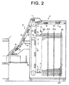
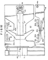
- a sheet sorter S comprises a plurality of (e.g., fifty) bins (sort trays) 4 which are disposed in fixed positions in a frame 3 at predetermined intervals in the vertical direction and receive a plurality of recorded sheets 2 ( Figure 3) discharged from an image recording apparatus 1 such as a printer to form a stack of the sheets 2 on each bin 4, a sheet transfer means 5 which transfers the sheets 2 discharged from the image recording apparatus 1 toward the bins 4, an indexer 6 which is movable up and down along the array of the sheet inlet ends 4a of the bins 4 and distributes the sheets 2 transferred by the sheet transfer means 5 to the respective bins 4, and a stapler 7 which is movable along the path of travel of the indexer 6 independently of the indexer 6.
- an image recording apparatus 1 such as a printer to form a stack of the sheets 2 on each bin 4
- a sheet transfer means 5 which transfers the sheets 2 discharged from the image recording apparatus 1 toward the bins 4
- an indexer 6 which is movable up and down along the
- the image recording apparatus 1 is a printer, especially a stencil printer
- a number of sheets can be printed in a short time and recorded sheets 2 carrying thereon wet ink are discharged at a high rate.
- the sheet transfer means 5 comprises a perforated conveyor belts 9 and 10 which convey the sheets 2 with the back side of the sheets 2 attracted against the belts 9 and 10 under vacuum applied by blowers 8 and a fan 11 which presses the sheets 2 against the belt 10 under an air pressure as clearly shown in Figure 2.
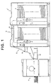
- the sheet sorter S is arranged so that a plurality of slaves S' having the same structure as the main sheet sorter S can be connected to the sheet sorter S as shown in Figure 1 in order to increase the total number of the bins 4.
- the slaves S' are connected to the main sheet sorter S on the side remote from the image recording apparatus 1.
- a sheet conveyor 12 is demountably mounted on an upper portion of the main sheet sorter S and the sheets 2 in the main sheet sorter S are transferred to the slaves S' by the sheet conveyor 12 when the slaves S' are connected to the main sheet sorter S.
- the image recording apparatus 1 is provided with a sheet tray 13 on which the discharged sheets 2 are stacked when sorting of the sheets 2 is not necessary. Further a control panel 14 and an exterior electric stapler 15 are mounted on the outer surface of the sheet sorter S.
- the stapler 7 waits in a waiting position retracted the path of the indexer 6 in a direction of width of the sheets 2 (in a vertical direction as seen in Figure 3) while the indexer 6 is moving up and down.
- the waiting position of the stapler 7 is such that the indexer 6 is brought into alignment with the stapler 7 or overlaps with the stapler 7 as seen in a side view of the sheet sorter S when the indexer 6 is moved to a position where it can distribute a sheet 2 to the lowermost bin 4.
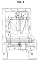
- side edges of the sheets 2 placed on each bin 4 are lined up along a side edge reference surface L1 defined by the inner surface of a sheet stack take-out door 18 which is rotatable about a pin 18a.
- a pair of side lineup rods 21a and 21b which push the sheet 2 in the direction of width of the sheet 2 and bring the side edge of the sheet 2 into abutment against the side edge reference surface L1
- a stopper member 22 of a resilient material such as rubber band which the leading edge of the sheet 2, which is released into the bin 4 at a high speed from the indexer 6, is brought into abutment against, thereby gently stopping the sheet 2, and a guide rail 26 along which a sheet stack ejector 25 (to be described later) is moved up and down.
- the side lineup rods 21a and 21b and the stopper member 22 are moved respectively along slots 23a, 23b and 24.
- the stopper member 22 is moved along the slot 24 left and right as seen in Figure 4 according to the size of the sheets 2 to be released from the indexer 6.
- the guide rail 26 doubles as a lineup rod which pushes the leading edge of the sheet 2 to move the sheet 2 toward the sheet inlet end 4a of the bin 4 so that the trailing edge of the sheet 2 is brought into abutment against a trailing edge reference surface L2.
- the guide rail 26 is provided with a flat vertical surface 26a facing toward the sheet inlet end 4a of the bin 4.
- the guide rail 26 is moved left and right as seen in Figure 4 by a drive mechanism (not shown) in an opening 27 formed in the bin 4.
- the side lineup rods 21a and 21b are moved by a drive mechanism (not shown) at angles to the direction in which the sheet 2 is fed into the bin 4 so that they are simultaneously moved toward and away from both the reference surfaces L1 and L2 and can act on various sizes of the sheets 2 in optimum positions according to the size of the sheets 2 to be handled. Further the angle at which the path of the side lineup rod 21b, which is at a larger distance from the trailing edge reference surface L2, is inclined to the feeding direction of the sheet 2 is smaller than that of the other side lineup rod 21a, and accordingly as the rods 21a and 21b are moved toward the side edge of the sheet 2, the distance between the rods 21a and 21b becomes smaller.
- the sheet stacks 20 ( Figure 4) on the respective bins 4 are ejected toward the stapler 7 beyond the trailing edge reference surface L2 by a predetermined length in sequence for stapling operation.
- a sheet stack ejector 25 is provided.
- the sheet stack ejector 25 can be moved by a drive mechanism (not shown) up and down in the openings 7 of the respective bins 4 along the guide rail 26 when the guide rail 26 is in the rightmost position shown in Figure 3.
- the sheet stack 20 on one of the bins 4 When the sheet stack 20 on one of the bins 4 is to be stapled, the sheet stack 20 on the bin 4 must be ejected from the sheet inlet end 4a of the bin 4 by a predetermined length, and accordingly the sheet stack ejector 25 is provided with an ejecting surface positioned at a distance not smaller than the predetermined length from the vertical surface of the guide rail 26.
- the guide rail 26 brings the trailing edges of the sheets 2 into alignment with each other on the trailing edge reference surface L2
- the sheet stack ejector 25 is moved upward or downward along the guide rail 26 to a position where the sheet stack ejector 25 does not interfere with the lineup operation of the guide rod 26.
- the sheet stack ejector 25 When stapling the sheet stack 20 on a selected bin 4, the sheet stack ejector 25 is first moved along the guide rail 26 to a predetermined position suitable for ejecting the sheet stack 20 on the selected bin 4 and the guide rail 26 is moved toward the sheet inlet end 4a of the selected bin 4 from the position shown in Figure 4. As the guide rail 26 is moved toward the sheet inlet end 4a, the sheet stack ejector 25 comes to be engaged with both the upper surface of a linear edge portion 4b ( Figure 4) of the opening 27 of the selected bin 4 and the lower surface of the linear edge portion 4b of the bin 4 just above the selected bin 4. Thus the sheet stack ejector 25 ejects the sheet stack 20 on the selected bin 4 toward the stapler 7 while moving toward the stapler 7 under the guidance of the surfaces of the engagement portions 4b of the adjacent bins 4 held therebetween.
- the stapler 7 is provided with a throat 7a into which the sheet stack 20 is inserted when stapling the sheet stack 20.
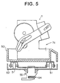
- the stapler unit comprises an elongated lift 52 which extends in the direction of width of the sheet 2 (left and right as seen in Figure 6) and is moved up and down along the path of travel of the indexer 6 by a drive means (not shown) and a base table 50 which is provided with four wheels 51 at four corners of the bottom surface thereof and is placed on the lift 52 to be movable in the direction of width of the sheet 2 on the lift 52.
- the stapler 7 and a reciprocal sheet pusher mechanism 49 for returning the stapled sheet stack 20 into the bin 4 are provided on the base table 50 integrally therewith.
- a pair of pulleys 53 are provided on opposite end portions of the lift 52 and an endless belt 54 is passes around the pulleys 53.
- a member 55 fixed to the base table 50 is connected to the endless belt 54.
- the stapler unit is in the waiting position, which is the lowermost position thereof, with the stapler 7 held in a position retracted from the path of travel of the indexer 6 in the direction of width of the sheet 2 when the indexer 6 is operating.
- the indexer 6 is positioned in a retracted position above the uppermost bin 4.
- the reciprocal sheet pusher mechanism 49 comprises a base bracket 60 fixed to the base table 50 of the stapler unit and a reciprocal pusher member 61 mounted on the base bracket 60.
- the base bracket 60 has a pair of walls 60a which are perpendicular to the direction of travel of the base table 50 on the lift 52 and spaced from each other in the direction of travel of the base table 50.
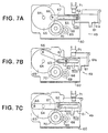
- the reciprocal pusher member 61 is provided with a vertical surface 61a adapted to be brought into abutment against the sheet stack 20 and is mounted to be movable between the walls 60a.
- each of the walls 60a is provided with a guide groove 63 extending left and right in Figures 7A to 7C and pins 62 projecting from the respective side surfaces of the pusher member 61 in perpendicular to the walls 60a are loosely fitted in the guide grooves 63.
- the pusher member 61 is mounted on the base bracket 60 to be linearly movable between the forward position shown in Figure 7A and the retracted position shown in Figure 7C.
- a shaft 64 is supported for rotation on the walls 60a and a larger diameter gear 65 is fixed to the shaft 64.
- a pin 66 is fixed to the gear 65 near the outer peripheral surface thereof and is connected to one of the pins 62 on the pusher member 61 by way of a link member 67.
- the larger diameter gear 65 is in mesh with an idler gear 70 which is in mesh with a gear 69 on the output shaft of an electric motor 68. Accordingly when the larger diameter gear 65 is rotated by the motor 68, the reciprocal pusher member 61 is moved back and forth as shown in Figures 7A to 7C.
- a sensor 71 which detects that the reciprocal pusher member 61 is in the retracted position is disposed on the base bracket 60.
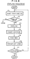
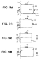
- the sheet stack 20 With the side edges of the sheets 2 in the sheet stack 20 in alignment with each other on the side edge reference surface L1 and the throat 7a of the stapler 7 opposed to a predetermined portion of the sheet stack 20 at which the sheet stack 20 is to be stapled as shown in Figure 9A, the sheet stack 20 is ejected toward the stapler 7 so that the trailing edge portion of the sheet stack 20 is inserted into the throat 7a of the stapler 7 as shown in Figure 9B. (step P1 in the flow chart shown in Figure 8) At this time, the reciprocal pusher member 61 of the reciprocal sheet pusher mechanism 49 is in the retracted position shown in Figure 7C.
- a sensor on the stapler 7 detects whether the sheet stack 20 is in the throat 7a of the stapler 7, and when the sensor detects that the sheet stack 20 is in the throat 7a of the stapler 7 (YES in step P2), the stapler 7 is actuated to staple the sheet stack 20 (step P3). Otherwise (NO in step P2), it is judged that error occurs.
- the base table 50 of the staple unit is moved on the lift 52 according to sheet size information input from the image recording apparatus 1 so that the reciprocal pusher member 61 of the reciprocal sheet pusher mechanism 49 is centered with respect to the stapled sheet stack 20 as shown in Figure 9C (step P4).
- the side lineup member 21 is moved to a position slightly retracted from the side edge of the sheet stack 20 remote from the side edge reference surface L1 as shown in Figure 9D.
- the reciprocal pusher member 61 is moved from the position shown in Figure 7C to the position shown in Figure 7A, whereby the sheet stack 20 is pushed back to the bin 4 as shown in Figure 9D. (step P5)
- the sheet stack 20 can be pushed back straight without increasing the load on the reciprocal pusher member 61.
- step P7 the reciprocal pusher member 61 is returned to the position shown in Figure 7C and the staple unit is moved downward to the bin 4 just below(step P6). Then the steps P1 to P6 are repeated until the sheet stacks 20 are all stapled. (step P7)
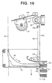
- Figures 10 and 11 show a member for defining the trailing edge reference surface L2.
- the trailing edge reference surface L2 extends along the array of the sheet inlet ends 4a of the bins 4 and is defined by a pair of strip-like spring members 30 each having a width d.
- the spring member 30 is in a continuous length and fed out from a roll in a casing 31 ( Figure 10) which is fixed to the frame 3 by way of a bracket 28 above the uppermost position of the indexer 6.
- the part of the spring member 30 extending outside the casing 31 is passed around a reel 32 and extends right downward.
- the leading end of the spring member 30 is fixed to a fixing member 33 which is provided just above the sheet discharge port 6b of the indexer 6 close thereto.
- the spring members 30 are long fed out from the casing 31 as the indexer 6 moves downward and close the sheet inlet ends 4a of the bins 4 which are above the sheet discharge end 6b of the indexer 6, thereby forming the trailing edge reference surface L2. As the indexer 6 moves upward the spring members 30 are taken up into the casing 31.
- a second strip-like spring member 34 which is smaller than the spring member 30 in width is employed to reinforce the spring member 30, thereby holding flat the spring member 30. That is, the second spring member 34 is in a continuous length and fed out from a roll in a casing 35 which is fixed to the frame 3 by way of a bracket 37 so that the longitudinal axis of the casing 35 is substantially perpendicular to that of the casing 31 of the spring member 30.
- the part of the second spring member 34 extending outside the casing 35 is passed around a reel 36 and extends downward with its one side edge in contact with the indexer side surface of the spring member 30 substantially perpendicularly thereto.
- the leading end of the second spring member 34 is fixed to the indexer 6 at a portion above the sheet discharge port 6b of the indexer 6.
- the second spring member 34 is fed out from the casing 35 as the indexer 6 moves downward and taken up into the casing as the indexer 6 moves upward.
- the second spring member 34 may be of a constant load spring such as "Conston ® ".
- hollow resilient members 38 are mounted on the indexer 6 below the sheet discharge port 6b on opposite sides of each spring member 20.
- the hollow resilient members 38 is formed of, for instance, "Mylar ®".
- Each resilient member 38 arcuately bulges toward the bin 4 and has an inclined surface which presses the trailing edge of the sheet stack 20 toward the guide rail 26.
- the sheet sorter S of this embodiment since the single reciprocal pusher member 61 is centered relative to the trailing edge of the sheet stack 20 when the reciprocal pusher member 61 pushes the sheet stack 20 back to the bin 4, the sheet stack 20 can be returned stright to the bin 4 irrespective of the size of the sheets 2 without providing a plurality of reciprocal pusher members 61.
- the reciprocal pusher member 61 is provided on the stapler 7, the reciprocal pusher member 61 and the stapler 7 can be moved by one drive mechanism.
- the trailing edges of the sheets 2 can be precisely aligned with each other on the reference surface L2 without providing each bin 4 with an erected surface defining the trailing edge reference surface as in conventional systems.
- the lineup rods 21a and 21b which push the sheets 2 in the direction of width to bring the side edges of the sheets 2 into abutment against the side edge reference surface L1, thereby lining up the side edges of the sheets 2 are movable so that they are simultaneously moved toward and away from both the reference surfaces L1 and L2, the lineup rods 21a and 21b can act on the sheets 2 in optimum positions according to the size of the sheets 2 to be handled. Further since the distance between the rods 21a and 21b becomes smaller as the rods 21a and 21b are moved toward the side edge of the sheet 2, the positions in which the rods 21a and 21b act on the sheets 2 can be further better.
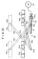
- a sheet sorter with a stapler in accordance with a second embodiment of the present invention will be described with reference to Figures 12 to 14, hereinbelow.
- the elements analogous to those in the first embodiment are given the same reference numerals and will not be described here.
- the stapler 7 and the reciprocal sheet pusher mechanism 49 are the same as those in the first embodiment and will not be described here.
- the sheets 2 are lined up with each other by bringing one side edges thereof in alignment with the side edge reference surface L1 irrespective of the size of the sheets 2, and accordingly the reciprocal pusher member 61 must be moved to the middle of the trailing edge of the sheet stack 20 the position of which varies according to the size of the sheets 2 as described above in conjunction with Figures 9A to 9D.
- the sheets 2 are lined up by bringing the longitudinal axes of the sheets 2 into alignment with a center line L3. That is, as shown in Figure 12, a pair of side lineup rods 81a and 81b which are rectangular in cross-section are provided near the sheet take-out doors 18 of the bins 4 to extends through the plurality of bins 4. Each bin 4 is provided with a wide cutaway portion 87 and the side lineup rods 81a and 81b are movable in the cutaway portion 87. Another pair of side lineup rods 83a and 83b are provided near the side edges of the bins 4 remote from the door 18. The side lineup rods 83a and 83b extends through openings 82a and 82b formed in the respective bins 4.
- the guide rail 26, the sheet stack ejector 25 and the opening 27 in which the guide rail 26 and the sheet stack ejector 25 are moved are symmetrical about the center line L3.
- the side lineup rods 81a and 81b near the door 18 are supported by a link mechanism 86 including upper and lower pairs of connecting rods 85a and 85b which are equal to each other in length.
- the upper pair of connecting rods 85a and 85b are connected for rotation to the upper end portions of the respective side lineup rods 81a and 81b by way of shafts 84a and 84b at their one ends, and the lower pair of connecting rods 85a and 85b are connected to the lower end portions of the respective side lineup rods 81a and 81b by way of shafts 84a and 84b at their one ends.
- the other ends of the upper and lower connecting rods 85a are connected for rotation to a vertical shaft 84e disposed between the side lineup rod 81b and the door 18 and the other ends of the upper and lower connecting rods 85b are connected for rotation to a vertical shaft 84d disposed between the side lineup rod 81a and the door 18.
- Each of the upper and lower pair of connecting rods 85a and 85b are supported for rotation on a shaft 84c at the middles thereof.
- the shaft 84d is stationary and the shaft 84e is movable left and right as seen in Figure 13.
- the side lineup rods 81a and 81b are moved toward the center line L3 and as the movable shaft 84e is moved rightward, the side lineup rods 81a and 81b are moved away from the center line L3.
- the link mechanism 86 With the arrangement of the link mechanism 86, as the movable shaft 84e is moved leftward, the shaft 84a is moved toward the centerline L3 along a linear line perpendicular to the center line L3 while the shaft 84b is moved toward the center line L3 approaching the shaft 84a. That is, as the side lineup rods 81a and 81b are moved toward the center line L3, the side lineup rod 81b moves toward the side lineup rod 81a, whereby the side lineup rods 81a and 81b can act on sheets of various sizes.
- the movable shaft 84e is moved in parallel to the center line L3 by a shaft drive mechanism 90.
- the shaft drive mechanism 90 comprises a guide rod 91 which extends in parallel to the center line L3 and is rotatable about its longitudinal axis.
- a lead screw 92 is formed on the outer surface of the guide rod 91 and an engagement pin 93 fixed to the lower end of the movable shaft 84e is in mesh with the lead screw 92.
- a driven pulley 94a is fixed to one end of the guide rod 91 coaxially with the guide rod 91 and a driving pulley 94b is fixed to an output shaft of a motor 95 which can be rotated in two directions.
- a driving belt 96 is passed around the pulleys 94a and 94b.
- the movable shaft 84e When the motor 95 rotates in one direction, the movable shaft 84e is moved leftward to move the side lineup rods 81a and 81b toward the center line L3 and when the motor 95 rotates in the other direction, the movable shaft 84e is moved rightward to move the side lineup rods 81a and 81b away from the center line L3.
- the side lineup rods 83a and 83b on the side of the center line L3 opposite to the side lineup rods 81a and 81b are moved toward and away from the center line L3 by a drive mechanism (not shown) in synchronization with the side lineup rods 81a and 81b, whereby the longitudinal axes of the sheets 2 are brought into alignment with the center line L3 irrespective of the size of the sheets 2.
- the reciprocal pusher member 61 may be moved to the same position, where it is aligned with the center line L3, irrespective of the size of the sheets 2.
- Symbol S in Figure 12 denotes a sensor which detects that the reciprocal pusher member 61 is in alignment with the center line L3.
- the sheet stack 20 can be pushed back into the bin 4 straight.
- the side lineup rods 81a, 81b, 83a and 83b may be slightly retracted away from the side edges of the sheet stack 20 by moving rightward the movable shaft 84e to assist the reciprocal sheet pusher mechanism 49 in pushing back the sheet stack 20 into the bin 4 straight.
- the reciprocal pusher member 61 is provided with the vertical surface 61a which is flat.
- the vertical surface 61a may be divided into a plurality of vertical surface portions which are flush with each other and are arranged in the direction of width of the sheets.
- a plurality of pusher members 61 may be provided to form an array.
- the pusher members 61 are arranged in the direction of width of the sheets so that their vertical surfaces 61a are in flush with each other and are centered to the trailing edge of the sheet stack so that the middle of the array is brought into alignment with the center line of the sheet stack.
- the term "a single reciprocal pusher member" should be broadly interpreted to include such an array of two or more reciprocal pusher members.
Landscapes
- Engineering & Computer Science (AREA)
- Mechanical Engineering (AREA)
- Collation Of Sheets And Webs (AREA)
- Folding Of Thin Sheet-Like Materials, Special Discharging Devices, And Others (AREA)
- Paper Feeding For Electrophotography (AREA)
Claims (6)
- Blattsortierer (5) mit einem Hefter (7), umfassend mehrere in vertikaler Richtung angeordnete Fächer (4), von denen jedes eine Mehrzahl von aus einer Bildaufzeichnungsvorrichtung (1) ausgetragenen Blättern aufnimmt und auf sich einen Blattstapel bildet, eine Blatttransfereinrichtung (5), die die von der Bildaufzeichnungsvorrichtung (1) ausgetragenen Blätter transferiert, und einen Indexierer (6), der entlang dem Feld von Blatteinlaßenden (4a) der Fächer (4) nach oben und nach unten bewegbar ist, um die Blätter aus der Blatttransfereinrichtung (5) in die jeweiligen Fächer (4) durch deren Blatteinlaßenden (4a) zu verteilen und zu liefern, einen Stapelausstoßer (25), der bewegbar ist, um den Blattstapel über das Blatteinlaßende (4a) des Fachs (4) um ein vorbestimmtes Stück in einer Richtung entgegen der Blattlieferrichtung auszustoßen, einen Hefter (7), der entlang dem Feld von Blatteinlaßenden (4a) der Fächer (4) nach oben und nach unten sowie in einer Richtung entlang dem Rand jedes Einlaßendes der Fächer bewegbar ist, um den auf jedem Fach (4) befindlichen, ausgestoßenen Blattstapel zu heften, und ein hin- und hergehendes Drückelement (61), das nach Abschluß des Heftens durch den Hefter (7) betätigt wird und den gehefteten Blattstapel wieder in das Fach (4) zurückdrückt, gekennzeichnet durch eine Zentriereinrichtung, die das hin- und hergehende Drückelement (61) bezüglich des Randes des Blattstapels ungeachtet der Größe der Blätter vor dem Zurückstoßen des gehefteten Blattstapels in das Fach (4) zentriert.
- Blattsortierer mit Hefter nach Anspruch 1, bei dem das hin- und hergehende Drückelement an dem Hefter angeordnet ist, um sich zusammen mit diesem zu bewegen.
- Blattsortierer mit Hefter nach Anspruch 1 oder 2, umfassend einen Bündigmacher zum Bündig-Machen der Ränder der Blätter in dem Stapel in jedem Fach.
- Blattsortierer mit Hefter nach Anspruch 3, bei dem der Bündigmacher aufweist: einen Seiten-Bündigmacher, der gegen die einen Seitenkanten der Blätter drückt, um die anderen Seitenkanten der Blätter in Anlage an einer vorbestimmten Seitenkanten-Referenzfläche zu bringen, so daß die anderen Seitenkanten miteinander in Fluchtung an der Referenzfläche gebracht werden, wobei der Seiten-Bündigmacher etwas von den einen Seitenkanten der Blätter zurückgezogen ist, bevor das hin- und hergehende Drückelement nach Abschluß des Heftens durch den Hefter betätigt wird.
- Blattsortierer mit Hefter nach Anspruch 4, bei dem die Seitenkanten-Referenzfläche jedes Fachs zumindest teilweise definiert wird durch die Innenfläche einer Blattentnahmetür des Sortierers, wenn diese Tür geschlossen ist.
- Blattsortierer mit Hefter nach Anspruch 3, bei dem der Bündigmacher ein Paar von Bündigmacherelementen aufweist, die einander in Breitenrichtung der Blätter gegenüberliegen und aufeinander zu bewegbar und voneinander abrückbar auf einander abgewandten Seiten der Blätter sind, wobei die Bündigmacherelemente aufeinander zu bewegt werden, um gegen die jeweiligen Seitenkanten des Blatts zu drücken und so die Längsachse des Blatts in Ausrichtung mit einer vorbestimmten Referenzlinie unabhängig von der Blattgröße zu halten, und die Bündigmacherelemente etwas von den Seitenkanten des Blattstapels zurückgezogen werden, bevor das hin- und hergehende Drückelement nach Abschluß des Heftens durch den Hefter betätigt wird.
Applications Claiming Priority (6)
| Application Number | Priority Date | Filing Date | Title |
|---|---|---|---|
| JP117513/96 | 1996-05-13 | ||
| JP11751396 | 1996-05-13 | ||
| JP11751396 | 1996-05-13 | ||
| JP05729997A JP3556424B2 (ja) | 1996-05-13 | 1997-03-12 | ステープラ付きシート分配装置 |
| JP5729997 | 1997-03-12 | ||
| JP57299/97 | 1997-03-12 |
Publications (3)
| Publication Number | Publication Date |
|---|---|
| EP0807537A2 EP0807537A2 (de) | 1997-11-19 |
| EP0807537A3 EP0807537A3 (de) | 1998-01-28 |
| EP0807537B1 true EP0807537B1 (de) | 2002-03-27 |
Family
ID=26398322
Family Applications (1)
| Application Number | Title | Priority Date | Filing Date |
|---|---|---|---|
| EP97107740A Expired - Lifetime EP0807537B1 (de) | 1996-05-13 | 1997-05-12 | Mit einer Heftvorrichtung versehenes Blattsortiergerät |
Country Status (4)
| Country | Link |
|---|---|
| US (1) | US5918871A (de) |
| EP (1) | EP0807537B1 (de) |
| JP (1) | JP3556424B2 (de) |
| DE (1) | DE69711260T2 (de) |
Families Citing this family (5)
| Publication number | Priority date | Publication date | Assignee | Title |
|---|---|---|---|---|
| EP0864523B1 (de) * | 1997-03-12 | 2001-05-23 | Riso Kagaku Corporation | Bogenverteilungsvorrichtung |
| US6260838B1 (en) * | 1999-03-29 | 2001-07-17 | Gradco (Japan) Ltd. | Stapling stacker |
| US6379063B1 (en) * | 2000-01-31 | 2002-04-30 | Hewlett-Packard Company | Programmable multiple staple positioning in post-processing of sheets from sheet handling equipment |
| US6394442B1 (en) * | 2000-09-14 | 2002-05-28 | Xerox Corporation | Kicker with adjustable contact points, for a sheet output apparatus in a printer or copier |
| US7747212B2 (en) * | 2007-02-01 | 2010-06-29 | Toshiba Tec Kabushiki Kaisha | Sheet processing apparatus and sheet processing method |
Family Cites Families (8)
| Publication number | Priority date | Publication date | Assignee | Title |
|---|---|---|---|---|
| DE68919915T2 (de) * | 1988-06-14 | 1995-05-04 | Canon Kk | Blattnachbearbeitungsvorrichtung. |
| US4925172A (en) * | 1988-10-31 | 1990-05-15 | Xerox Corporation | Small inexpensive finisher |
| US5024430A (en) * | 1989-01-18 | 1991-06-18 | Ricoh Company, Ltd. | Paper handling apparatus |
| US5064181A (en) * | 1989-01-19 | 1991-11-12 | Ricoh Company, Ltd. | Paper handling apparatus |
| US5048819A (en) * | 1990-01-15 | 1991-09-17 | Ikegami Tsushinki Co., Ltd. | Sorting machine having an uppermost tray which is only used in the non-sorting mode |
| US5098074A (en) * | 1991-01-25 | 1992-03-24 | Xerox Corporation | Finishing apparatus |
| US5409202A (en) * | 1994-03-18 | 1995-04-25 | Xerox Corporation | Integral disk type inverter-stacker and stapler |
| JPH08108377A (ja) * | 1994-08-08 | 1996-04-30 | Nisca Corp | ステープラ及びそれを用いた製本装置 |
-
1997
- 1997-03-12 JP JP05729997A patent/JP3556424B2/ja not_active Expired - Fee Related
- 1997-05-12 EP EP97107740A patent/EP0807537B1/de not_active Expired - Lifetime
- 1997-05-12 DE DE69711260T patent/DE69711260T2/de not_active Expired - Fee Related
- 1997-05-13 US US08/855,636 patent/US5918871A/en not_active Expired - Fee Related
Also Published As
| Publication number | Publication date |
|---|---|
| DE69711260D1 (de) | 2002-05-02 |
| DE69711260T2 (de) | 2002-07-18 |
| JPH1029761A (ja) | 1998-02-03 |
| JP3556424B2 (ja) | 2004-08-18 |
| US5918871A (en) | 1999-07-06 |
| EP0807537A3 (de) | 1998-01-28 |
| EP0807537A2 (de) | 1997-11-19 |
Similar Documents
| Publication | Publication Date | Title |
|---|---|---|
| US5971384A (en) | Finishing apparatus and image forming apparatus using the same | |
| US6022011A (en) | Sheet finisher including binding, folding and stacking | |
| US5590871A (en) | Recording sheet finishing apparatus | |
| JP3304234B2 (ja) | ステープル装置 | |
| US5741009A (en) | Sheet sorting apparatus | |
| US5895036A (en) | Finishing apparatus | |
| US7883079B2 (en) | Sheet processing apparatus | |
| EP0807537B1 (de) | Mit einer Heftvorrichtung versehenes Blattsortiergerät | |
| EP0807536B1 (de) | Mechanismus zum Auswerfen von Bogenstapeln für Blattsortiergerät | |
| US5924689A (en) | Sheet sorter with stapler | |
| JPH10279160A (ja) | 用紙の排紙処理装置 | |
| US5806850A (en) | Sheet sorter | |
| JP2565364B2 (ja) | シート分類装置 | |
| US5222721A (en) | Sorter with casing movable in a transverse direction to the direction of sheet delivery | |
| JP3325193B2 (ja) | ソータ | |
| JP2000086059A (ja) | 用紙揃え機構 | |
| US5192065A (en) | Sorter with trays rotatable into a stapling position | |
| JP3041727B2 (ja) | ソータ | |
| JP2002241030A (ja) | 用紙処理装置 | |
| JP3013109B2 (ja) | ステイプラ装置を備えたソータ | |
| JP3280304B2 (ja) | フィニッシャー装置及びこれを用いた画像形成装置 | |
| JPH03256797A (ja) | ソーター綴じ装置 | |
| JP2916712B2 (ja) | ソータ | |
| JP3114043B2 (ja) | 用紙取り出し装置 | |
| JPH04112857U (ja) | ステイプラ装置を備えたソータ |
Legal Events
| Date | Code | Title | Description |
|---|---|---|---|
| PUAI | Public reference made under article 153(3) epc to a published international application that has entered the european phase |
Free format text: ORIGINAL CODE: 0009012 |
|
| AK | Designated contracting states |
Kind code of ref document: A2 Designated state(s): DE FR GB |
|
| PUAL | Search report despatched |
Free format text: ORIGINAL CODE: 0009013 |
|
| AK | Designated contracting states |
Kind code of ref document: A3 Designated state(s): DE FR GB |
|
| 17P | Request for examination filed |
Effective date: 19980714 |
|
| 17Q | First examination report despatched |
Effective date: 19990712 |
|
| RAP1 | Party data changed (applicant data changed or rights of an application transferred) |
Owner name: RISO KAGAKU CORPORATION |
|
| GRAG | Despatch of communication of intention to grant |
Free format text: ORIGINAL CODE: EPIDOS AGRA |
|
| GRAG | Despatch of communication of intention to grant |
Free format text: ORIGINAL CODE: EPIDOS AGRA |
|
| GRAH | Despatch of communication of intention to grant a patent |
Free format text: ORIGINAL CODE: EPIDOS IGRA |
|
| GRAH | Despatch of communication of intention to grant a patent |
Free format text: ORIGINAL CODE: EPIDOS IGRA |
|
| REG | Reference to a national code |
Ref country code: GB Ref legal event code: IF02 |
|
| GRAA | (expected) grant |
Free format text: ORIGINAL CODE: 0009210 |
|
| AK | Designated contracting states |
Kind code of ref document: B1 Designated state(s): DE FR GB |
|
| REF | Corresponds to: |
Ref document number: 69711260 Country of ref document: DE Date of ref document: 20020502 |
|
| ET | Fr: translation filed | ||
| PLBE | No opposition filed within time limit |
Free format text: ORIGINAL CODE: 0009261 |
|
| STAA | Information on the status of an ep patent application or granted ep patent |
Free format text: STATUS: NO OPPOSITION FILED WITHIN TIME LIMIT |
|
| 26N | No opposition filed |
Effective date: 20021230 |
|
| PGFP | Annual fee paid to national office [announced via postgrant information from national office to epo] |
Ref country code: DE Payment date: 20080515 Year of fee payment: 12 |
|
| PGFP | Annual fee paid to national office [announced via postgrant information from national office to epo] |
Ref country code: GB Payment date: 20080514 Year of fee payment: 12 |
|
| GBPC | Gb: european patent ceased through non-payment of renewal fee |
Effective date: 20090512 |
|
| REG | Reference to a national code |
Ref country code: FR Ref legal event code: ST Effective date: 20100129 |
|
| PG25 | Lapsed in a contracting state [announced via postgrant information from national office to epo] |
Ref country code: FR Free format text: LAPSE BECAUSE OF NON-PAYMENT OF DUE FEES Effective date: 20090602 |
|
| PGFP | Annual fee paid to national office [announced via postgrant information from national office to epo] |
Ref country code: FR Payment date: 20080514 Year of fee payment: 12 |
|
| PG25 | Lapsed in a contracting state [announced via postgrant information from national office to epo] |
Ref country code: GB Free format text: LAPSE BECAUSE OF NON-PAYMENT OF DUE FEES Effective date: 20090512 |
|
| PG25 | Lapsed in a contracting state [announced via postgrant information from national office to epo] |
Ref country code: DE Free format text: LAPSE BECAUSE OF NON-PAYMENT OF DUE FEES Effective date: 20091201 |