EP0802334A1 - Verbindungsmechanismus für strukturelemente - Google Patents
Verbindungsmechanismus für strukturelemente Download PDFInfo
- Publication number
- EP0802334A1 EP0802334A1 EP94919857A EP94919857A EP0802334A1 EP 0802334 A1 EP0802334 A1 EP 0802334A1 EP 94919857 A EP94919857 A EP 94919857A EP 94919857 A EP94919857 A EP 94919857A EP 0802334 A1 EP0802334 A1 EP 0802334A1
- Authority
- EP
- European Patent Office
- Prior art keywords
- structural members
- members
- engaging
- structural
- slot
- Prior art date
- Legal status (The legal status is an assumption and is not a legal conclusion. Google has not performed a legal analysis and makes no representation as to the accuracy of the status listed.)
- Granted
Links
- 230000007246 mechanism Effects 0.000 title claims abstract description 96
- 238000004891 communication Methods 0.000 claims abstract description 37
- 238000005304 joining Methods 0.000 claims description 32
- 230000000717 retained effect Effects 0.000 claims description 14
- 230000008878 coupling Effects 0.000 claims description 3
- 238000010168 coupling process Methods 0.000 claims description 3
- 238000005859 coupling reaction Methods 0.000 claims description 3
- 229910000838 Al alloy Inorganic materials 0.000 description 4
- 238000003780 insertion Methods 0.000 description 4
- 230000037431 insertion Effects 0.000 description 4
- 238000000034 method Methods 0.000 description 4
- 230000008569 process Effects 0.000 description 4
- 229910000975 Carbon steel Inorganic materials 0.000 description 3
- ZOKXTWBITQBERF-UHFFFAOYSA-N Molybdenum Chemical compound [Mo] ZOKXTWBITQBERF-UHFFFAOYSA-N 0.000 description 3
- 229910000831 Steel Inorganic materials 0.000 description 3
- 239000010962 carbon steel Substances 0.000 description 3
- 239000012530 fluid Substances 0.000 description 3
- 238000005242 forging Methods 0.000 description 3
- 238000002347 injection Methods 0.000 description 3
- 239000007924 injection Substances 0.000 description 3
- 238000005495 investment casting Methods 0.000 description 3
- 238000003754 machining Methods 0.000 description 3
- 229910052751 metal Inorganic materials 0.000 description 3
- 239000002184 metal Substances 0.000 description 3
- 239000011733 molybdenum Substances 0.000 description 3
- 229910052750 molybdenum Inorganic materials 0.000 description 3
- 239000000843 powder Substances 0.000 description 3
- 238000005245 sintering Methods 0.000 description 3
- 239000010935 stainless steel Substances 0.000 description 3
- 229910001220 stainless steel Inorganic materials 0.000 description 3
- 239000010959 steel Substances 0.000 description 3
- 238000003825 pressing Methods 0.000 description 2
- 230000009471 action Effects 0.000 description 1
- 229910052782 aluminium Inorganic materials 0.000 description 1
- XAGFODPZIPBFFR-UHFFFAOYSA-N aluminium Chemical compound [Al] XAGFODPZIPBFFR-UHFFFAOYSA-N 0.000 description 1
- 230000000712 assembly Effects 0.000 description 1
- 238000000429 assembly Methods 0.000 description 1
- 230000000295 complement effect Effects 0.000 description 1
- 238000004519 manufacturing process Methods 0.000 description 1
- 239000007769 metal material Substances 0.000 description 1
- 230000003014 reinforcing effect Effects 0.000 description 1
Images


Classifications
-
- F—MECHANICAL ENGINEERING; LIGHTING; HEATING; WEAPONS; BLASTING
- F16—ENGINEERING ELEMENTS AND UNITS; GENERAL MEASURES FOR PRODUCING AND MAINTAINING EFFECTIVE FUNCTIONING OF MACHINES OR INSTALLATIONS; THERMAL INSULATION IN GENERAL
- F16B—DEVICES FOR FASTENING OR SECURING CONSTRUCTIONAL ELEMENTS OR MACHINE PARTS TOGETHER, e.g. NAILS, BOLTS, CIRCLIPS, CLAMPS, CLIPS OR WEDGES; JOINTS OR JOINTING
- F16B7/00—Connections of rods or tubes, e.g. of non-circular section, mutually, including resilient connections
- F16B7/04—Clamping or clipping connections
-
- B—PERFORMING OPERATIONS; TRANSPORTING
- B23—MACHINE TOOLS; METAL-WORKING NOT OTHERWISE PROVIDED FOR
- B23Q—DETAILS, COMPONENTS, OR ACCESSORIES FOR MACHINE TOOLS, e.g. ARRANGEMENTS FOR COPYING OR CONTROLLING; MACHINE TOOLS IN GENERAL CHARACTERISED BY THE CONSTRUCTION OF PARTICULAR DETAILS OR COMPONENTS; COMBINATIONS OR ASSOCIATIONS OF METAL-WORKING MACHINES, NOT DIRECTED TO A PARTICULAR RESULT
- B23Q3/00—Devices holding, supporting, or positioning work or tools, of a kind normally removable from the machine
- B23Q3/02—Devices holding, supporting, or positioning work or tools, of a kind normally removable from the machine for mounting on a work-table, tool-slide, or analogous part
- B23Q3/10—Auxiliary devices, e.g. bolsters, extension members
- B23Q3/102—Auxiliary devices, e.g. bolsters, extension members for fixing elements in slots
-
- F—MECHANICAL ENGINEERING; LIGHTING; HEATING; WEAPONS; BLASTING
- F16—ENGINEERING ELEMENTS AND UNITS; GENERAL MEASURES FOR PRODUCING AND MAINTAINING EFFECTIVE FUNCTIONING OF MACHINES OR INSTALLATIONS; THERMAL INSULATION IN GENERAL
- F16B—DEVICES FOR FASTENING OR SECURING CONSTRUCTIONAL ELEMENTS OR MACHINE PARTS TOGETHER, e.g. NAILS, BOLTS, CIRCLIPS, CLAMPS, CLIPS OR WEDGES; JOINTS OR JOINTING
- F16B7/00—Connections of rods or tubes, e.g. of non-circular section, mutually, including resilient connections
- F16B7/04—Clamping or clipping connections
- F16B7/044—Clamping or clipping connections for rods or tubes being in angled relationship
- F16B7/0446—Clamping or clipping connections for rods or tubes being in angled relationship for tubes using the innerside thereof
- F16B7/0453—Clamping or clipping connections for rods or tubes being in angled relationship for tubes using the innerside thereof the tubes being drawn towards each other
- F16B7/046—Clamping or clipping connections for rods or tubes being in angled relationship for tubes using the innerside thereof the tubes being drawn towards each other by rotating an eccenter-mechanism
-
- F—MECHANICAL ENGINEERING; LIGHTING; HEATING; WEAPONS; BLASTING
- F16—ENGINEERING ELEMENTS AND UNITS; GENERAL MEASURES FOR PRODUCING AND MAINTAINING EFFECTIVE FUNCTIONING OF MACHINES OR INSTALLATIONS; THERMAL INSULATION IN GENERAL
- F16B—DEVICES FOR FASTENING OR SECURING CONSTRUCTIONAL ELEMENTS OR MACHINE PARTS TOGETHER, e.g. NAILS, BOLTS, CIRCLIPS, CLAMPS, CLIPS OR WEDGES; JOINTS OR JOINTING
- F16B7/00—Connections of rods or tubes, e.g. of non-circular section, mutually, including resilient connections
- F16B7/04—Clamping or clipping connections
- F16B7/044—Clamping or clipping connections for rods or tubes being in angled relationship
- F16B7/0446—Clamping or clipping connections for rods or tubes being in angled relationship for tubes using the innerside thereof
- F16B7/0453—Clamping or clipping connections for rods or tubes being in angled relationship for tubes using the innerside thereof the tubes being drawn towards each other
- F16B7/0466—Clamping or clipping connections for rods or tubes being in angled relationship for tubes using the innerside thereof the tubes being drawn towards each other by a screw-threaded stud with a conical tip acting on an inclined surface
-
- F—MECHANICAL ENGINEERING; LIGHTING; HEATING; WEAPONS; BLASTING
- F16—ENGINEERING ELEMENTS AND UNITS; GENERAL MEASURES FOR PRODUCING AND MAINTAINING EFFECTIVE FUNCTIONING OF MACHINES OR INSTALLATIONS; THERMAL INSULATION IN GENERAL
- F16B—DEVICES FOR FASTENING OR SECURING CONSTRUCTIONAL ELEMENTS OR MACHINE PARTS TOGETHER, e.g. NAILS, BOLTS, CIRCLIPS, CLAMPS, CLIPS OR WEDGES; JOINTS OR JOINTING
- F16B7/00—Connections of rods or tubes, e.g. of non-circular section, mutually, including resilient connections
- F16B7/18—Connections of rods or tubes, e.g. of non-circular section, mutually, including resilient connections using screw-thread elements
- F16B7/187—Connections of rods or tubes, e.g. of non-circular section, mutually, including resilient connections using screw-thread elements with sliding nuts or other additional connecting members for joining profiles provided with grooves or channels
-
- E—FIXED CONSTRUCTIONS
- E04—BUILDING
- E04B—GENERAL BUILDING CONSTRUCTIONS; WALLS, e.g. PARTITIONS; ROOFS; FLOORS; CEILINGS; INSULATION OR OTHER PROTECTION OF BUILDINGS
- E04B1/00—Constructions in general; Structures which are not restricted either to walls, e.g. partitions, or floors or ceilings or roofs
- E04B1/38—Connections for building structures in general
- E04B1/58—Connections for building structures in general of bar-shaped building elements
- E04B2001/5868—Hinged connections
-
- F—MECHANICAL ENGINEERING; LIGHTING; HEATING; WEAPONS; BLASTING
- F16—ENGINEERING ELEMENTS AND UNITS; GENERAL MEASURES FOR PRODUCING AND MAINTAINING EFFECTIVE FUNCTIONING OF MACHINES OR INSTALLATIONS; THERMAL INSULATION IN GENERAL
- F16B—DEVICES FOR FASTENING OR SECURING CONSTRUCTIONAL ELEMENTS OR MACHINE PARTS TOGETHER, e.g. NAILS, BOLTS, CIRCLIPS, CLAMPS, CLIPS OR WEDGES; JOINTS OR JOINTING
- F16B2200/00—Constructional details of connections not covered for in other groups of this subclass
- F16B2200/20—Connections with hook-like parts gripping behind a blind side of an element to be connected
- F16B2200/205—Connections with hook-like parts gripping behind a blind side of an element to be connected the hook being a separate retainer
-
- F—MECHANICAL ENGINEERING; LIGHTING; HEATING; WEAPONS; BLASTING
- F16—ENGINEERING ELEMENTS AND UNITS; GENERAL MEASURES FOR PRODUCING AND MAINTAINING EFFECTIVE FUNCTIONING OF MACHINES OR INSTALLATIONS; THERMAL INSULATION IN GENERAL
- F16B—DEVICES FOR FASTENING OR SECURING CONSTRUCTIONAL ELEMENTS OR MACHINE PARTS TOGETHER, e.g. NAILS, BOLTS, CIRCLIPS, CLAMPS, CLIPS OR WEDGES; JOINTS OR JOINTING
- F16B2200/00—Constructional details of connections not covered for in other groups of this subclass
- F16B2200/30—Dovetail-like connections
-
- F—MECHANICAL ENGINEERING; LIGHTING; HEATING; WEAPONS; BLASTING
- F16—ENGINEERING ELEMENTS AND UNITS; GENERAL MEASURES FOR PRODUCING AND MAINTAINING EFFECTIVE FUNCTIONING OF MACHINES OR INSTALLATIONS; THERMAL INSULATION IN GENERAL
- F16B—DEVICES FOR FASTENING OR SECURING CONSTRUCTIONAL ELEMENTS OR MACHINE PARTS TOGETHER, e.g. NAILS, BOLTS, CIRCLIPS, CLAMPS, CLIPS OR WEDGES; JOINTS OR JOINTING
- F16B2200/00—Constructional details of connections not covered for in other groups of this subclass
- F16B2200/40—Clamping arrangements where clamping parts are received in recesses of elements to be connected
- F16B2200/403—Threaded clamping parts
-
- H—ELECTRICITY
- H02—GENERATION; CONVERSION OR DISTRIBUTION OF ELECTRIC POWER
- H02B—BOARDS, SUBSTATIONS OR SWITCHING ARRANGEMENTS FOR THE SUPPLY OR DISTRIBUTION OF ELECTRIC POWER
- H02B1/00—Frameworks, boards, panels, desks, casings; Details of substations or switching arrangements
- H02B1/01—Frameworks
- H02B1/012—Details of mechanical connections
-
- Y—GENERAL TAGGING OF NEW TECHNOLOGICAL DEVELOPMENTS; GENERAL TAGGING OF CROSS-SECTIONAL TECHNOLOGIES SPANNING OVER SEVERAL SECTIONS OF THE IPC; TECHNICAL SUBJECTS COVERED BY FORMER USPC CROSS-REFERENCE ART COLLECTIONS [XRACs] AND DIGESTS
- Y10—TECHNICAL SUBJECTS COVERED BY FORMER USPC
- Y10S—TECHNICAL SUBJECTS COVERED BY FORMER USPC CROSS-REFERENCE ART COLLECTIONS [XRACs] AND DIGESTS
- Y10S285/00—Pipe joints or couplings
- Y10S285/906—Equivalents
-
- Y—GENERAL TAGGING OF NEW TECHNOLOGICAL DEVELOPMENTS; GENERAL TAGGING OF CROSS-SECTIONAL TECHNOLOGIES SPANNING OVER SEVERAL SECTIONS OF THE IPC; TECHNICAL SUBJECTS COVERED BY FORMER USPC CROSS-REFERENCE ART COLLECTIONS [XRACs] AND DIGESTS
- Y10—TECHNICAL SUBJECTS COVERED BY FORMER USPC
- Y10T—TECHNICAL SUBJECTS COVERED BY FORMER US CLASSIFICATION
- Y10T403/00—Joints and connections
- Y10T403/34—Branched
- Y10T403/341—Three or more radiating members
-
- Y—GENERAL TAGGING OF NEW TECHNOLOGICAL DEVELOPMENTS; GENERAL TAGGING OF CROSS-SECTIONAL TECHNOLOGIES SPANNING OVER SEVERAL SECTIONS OF THE IPC; TECHNICAL SUBJECTS COVERED BY FORMER USPC CROSS-REFERENCE ART COLLECTIONS [XRACs] AND DIGESTS
- Y10—TECHNICAL SUBJECTS COVERED BY FORMER USPC
- Y10T—TECHNICAL SUBJECTS COVERED BY FORMER US CLASSIFICATION
- Y10T403/00—Joints and connections
- Y10T403/36—Three or more serial joints, at least one diverse
Definitions
- the present invention relates to a joint mechanism for joining structural members while keeping passages defined in the structural members in communication with each other when the structural members are to be assembled into a structural assembly.
- the applicant of the present application has proposed an actuator which includes a drive means such as a motor or the like and a movable member that is displaceable by the drive means, the drive means and the movable member being accommodated in a recess in a structural member which comprises a substantially elongate columnar body, and also proposed a structural assembly (Japanese laid-open patent publications Nos. 5-69352, 5-180295, 5-180296, and 5-180297).
- structural member which represents a concept including both an outer frame of an actuator and a columnar elongate member. The term will be used below as meaning the same concept.
- a plurality of structural members which are of substantially the same shape may be assembled by joint mechanisms into a structural assembly that has a desired function.
- FIG. 1 of the accompanying drawings One example of the joint mechanisms disclosed in the above publications is a locking member 2 for joining structural members as shown in FIG. 1 of the accompanying drawings.
- one end of the locking member 2 is inserted into a hole 6 defined longitudinally in a structural member 4, and a head 8 on the other end of the locking member 2 is loosely fitted in a slot 10 defined in another structural member 4a.
- a screw 14 is threaded through a plate 12 transversely into the structural member 4 until a tip end 16 of the screw 14 is held against a slanting surface 18 of a notch defined substantially centrally in the locking member 2.
- the tip end 16 is of such a tapered configuration that when the screw 14 is threaded in, the tip end 16 presses the slanting surface 18, displacing the locking member 2 in the direction indicated by the arrow A in FIG. 3 of the accompanying drawings.
- the head 8 of the locking member 2 pulls an inner wall surface of the other structural member 4a also in the direction indicated by the arrow A.
- the structural members 4, 4a are fixedly joined to each other substantially perpendicularly to each other as shown in FIGS. 2 and 3 of the accompanying drawings.
- the locking member 2 is normally biased in the direction indicated by the arrow B under resilient forces from a spring 19.
- the present invention has been made in relation to the above proposals. It is an object of the present invention to provide an improved joint mechanism for joining structural members while keeping passages defined in the structural members in communication with each other.
- Another object of the present invention is to provide a joint mechanism which joins structural members substantially in line or perpendicularly through slots defined longitudinally in the structural members, so that a structural assembly can simply be constructed of the joined structural members.
- Still another object of the present invention is to provide a joint mechanism which is capable of joining structural members angularly movably to each other at a freely selected angle between the joined structural members.
- a passage communication member is fitted in a passage in one of the structural members, and has a head which is mounted in a slot in the other of the structural members.
- the passage in one of the structural members and a passage in the other of the structural members are held in communication with each other through a through hole that is defined in the passage communication member.
- a first engaging member is inserted in a recess defined in one of the structural members, and a second engaging member is retained in a slot in the other of the structural members.
- structural members 20, 20a are in the form of substantially identical, elongate columnar bodies.
- the structural member 20 has substantially identical slots 22 of substantially T-shaped cross section which are defined respectively in outer side surfaces thereof. Since the structural members 20, 20a are substantially identical to each other in structure, the structural member 20 will be described below, and the structural member 20a will not be described below.
- Each of the slots 22 has inlet edges which have respective substantially V-shaped grooves 24 defined therein that extend along the slot 22.
- a substantially channel-shaped cover 22 is mounted in the slot 22 with teeth 25 of the cover 22 engaging in the respective V-shaped grooves 24.
- Each of the slots 22 has an enlarged portion 26 which is spread from the inlet edges in directions perpendicular to the axis of the structural member 20, and a cavity 28 which is constricted inwardly from the enlarged portion 26 and extends to a flat bottom 27.
- the structural member 20 also has a pair of substantially circular recesses 29a, 29b (mounting recesses) defined in its upper surface closely to respective opposite ends thereof and communicating with the slot 22 in the upper surface.
- the structural member 20 further includes a first passage 30 of large diameter defined therein which extends along the axis thereof, second passages 32a ⁇ 32d of small diameter defined therein near the four corners thereof and extending in the longitudinal direction of the structural member 20, and third passages 34a ⁇ 34d defined therein which extends along the axis thereof, the third passages 34a ⁇ 34d being positioned between the first passage 30 and the second passages 32a ⁇ 32d.
- a plug 36 (see FIG. 4) is mounted in an end of the structural member 20a and closes the first passage 30.
- the structural member 20a has a hole 38 (see FIG. 5) defined therein in communication with the first passage 30.
- a joint mechanism for joining structural members includes a passage communication member 42 (see FIGS. 4 and 5) having a through hole 40 defined therein which provides communication between the first passage 30 in the structural member 20 and the first passage 30 in the other structural member 20a.
- the joint mechanism also has a first engaging member 44 inserted in the recess 29a (29b) in the structural member 20, a second engaging member 46 retained in one of the slots 22 in the structural member 20a, and a bolt 48 interconnecting the first engaging member 44 and the second engaging member 46.
- the structural members 20, 20a are joined to each other by mounting the first engaging member 44 in the structural member 20, mounting the second engaging member 46 in the structural member 20a, and then coupling the first engaging member 44 and the second engaging member 46 to each other with the bolt 48.
- the passage communication member 42 comprises a tubular body 50 fitted in the first passage 30 extending axially in the structural member 20, and a head 54 having a projection 52 fitted in the hole 38 in the structural member 20a.
- the head 54 is of a substantially T shape and is fitted in the slot 22 in the structural member 20a.
- the tubular body 50 and the head 54 are integrally formed with each other, and a seal 56 is mounted in an annular groove defined in the tubular body 50.
- An elastic seal 58 is mounted on a surface of the head 54 around the projection 52 and held against an inner wall surface of the slot 22. Under the resiliency of the elastic seal 58, the head 54 is pressed toward the structural member 20 to hold the passage communication member 42 in the slot 22 (see FIG. 5).
- the first engaging member 44 has a substantially circular profile complementary in shape to the recesses 29a, 29b, and has a rectangular hole 60 defined therein and a screw hole 61 defined therein which extends from the bottom of the rectangular hole 60 to an outer surface of the first engaging member 44.
- the second engaging member 46 has a substantially T-shaped head 62 on one end thereof which is held in the slot 22 and a threaded hole 64 defined in an opposite end remote from the head 62 for receiving the bolt 48 therein.
- the first and second engaging members 44, 46 should preferably be made of aluminum alloy, stainless steel, carbon steel, molybdenum steel, or the like, and manufactured by precision casting, precision (cold) forging, lost-wax process, metal powder injection sintering, or the like.
- the first and second engaging members 44, 46 thus produced have a high strength, require no substantial subsequent machining, and are light in weight and low in cost.
- the joint mechanism according to this embodiment which is basically of the above structure, operates as follows:
- the substantially T-shaped head 54 of the passage communication member 42 is inserted from an end of the structural member 20a into one of the slots 22 therein while the longitudinal axis of the head 54 is being aligned with the longitudinal axis of the slot 22.
- the head 54 is inserted, it is twisted about 90° into locking engagement with an inner wall surface of the slot 22, and the projection 52 is fitted into the hole 38 communicating with the first passage 30 (see FIG. 5).
- the seal 58 around the projection 52 elastically presses the inner wall surface of the slot 22, securing retaining the substantially T-shaped head 54 in the slot 22.
- the passage communication member 42 is held in position in the slot 22 in the structural member 20a, with the tubular body 50 projecting out of the slot 22.
- the other structural member 20 is oriented substantially perpendicularly to the structural member 20a, and an end of the structural member 20 is brought toward the structural member 20a until the tubular body 50 is fitted into the first passage 30 in the structural member 20. Therefore, the first passage 30 in the structural member 20a and the first passage 30 in the structural member 20 are held in communication with each other through the through hole 40 in the passage communication member 42.
- the seal 56 disposed around the passage communication member 42 fitted in the first passage 30 serves to hermetically seal the first passage 30.
- the first engaging member 44 is inserted into the substantially circular recess 29a in the structural member 20, and the head 62 of the second engaging member 46 is inserted from the end of the structural member 20a into the slot 22 therein.
- the bolt 48 placed in the slot 22 in the structural member 20, is threaded through the screw hole 61 in the first engaging member 44 into the threaded hole 64 in the second engaging member 46.
- the head 62 of the second engaging member 46 is pulled in the direction indicated by the arrow X in FIG. 6.
- the structural member 20a is displaced toward the structural member 20, and they are firmly joined to each other.
- the joint mechanism according to this embodiment is thus effective in firmly joining the structural members 20, 20a to each other while keeping the first passages 30 in the structural members 20, 20a in communication with each other.
- FIG. 7 shows an assembly of plural structural members joined by joint mechanisms according to this embodiment.
- the assembly generally denoted by 100, comprises a plurality of structural members 102 which form an assembly skeleton, a plurality of actuators 104, 106, 108, 110, 112, 114, 116, 118, 120, a plurality of balancers 122, 124, 126 disposed parallel to the actuators 106, 112, 116, first and second working tables 128, 130, a plurality of workpieces 132, a plurality of workpiece holding plates 134, a plurality of movable bodies 136, 138, 140, 142, 144, 146, 148 combined with the actuators, a suction pad 150 and a mechanical hand 152 which function as workpiece gripping means, and a plurality of cylinders 156 having respective projecting cylinder rods 154.
- Sequencers 158, 160 with programming boards, which function as actuator controllers, are mounted on the upper surface of one of the structural members 102.
- Some of the structural members 102 are assembled in substantially rectangular structures each including a diagonal structural member 102 whose opposite ends are associated with joint members 162, 164 for reinforcing joined regions.
- Some of the structural members 102 are joined in line with each other by joint mechanisms 165, and some of the structural members 102 are substantially perpendicularly joined by joint mechanisms 167.
- the first working table 128 will mainly be described in detail below.
- the actuator 106 is vertically mounted on and substantially perpendicularly joined to the actuator 104 which is substantially horizontally arranged.
- the balancer 122 is disposed parallel to the actuator 106.
- the actuator 106 serves to move the actuator 108 fixed to the movable body 138 thereof in substantially vertical directions.
- a cylinder 166, to which the suction pad 150 is attached, is supported on the movable body 140 of the actuator 108 connected perpendicularly to the actuator 106.
- the cylinder 156 is attached to the movable body 142 of the actuator 110, and the cylinder rod 154 thereof serves to position a workpiece 132.
- Motor boxes 168 are disposed respectively in the actuators 104, 106, 108, 110, 112, 114, 116, 118, 120 and have respective upper surfaces lying flush with, but not projecting from, the upper surfaces of these actuators.
- the first working table 128 operates as follows: Compressed air is supplied to the cylinder 166 coupled to the actuator 108 through fluid passages (the first, second, and third passages 30, 32a ⁇ 32d, 34a ⁇ 34d) in the structural members 102. Under the pressure of the supplied compressed air, the cylinder rod of the cylinder 166 is displaced downwardly, and a workpiece 132 placed on the workpiece holding plate 134 is attracted by the suction pad 150. Compressed air is supplied again to the cylinder 166, displacing the cylinder rod upwardly, and the movable body 136 of the actuator 104 is moved.
- the actuator 104 is inactivated when the workpiece 132 attracted by the suction pad 150 reaches a position above a desired position on the workpiece holding plate 134. Then, the movable body 138 of the actuator 106 is moved downwardly until the attracted workpiece 132 is inserted into a desired hole in the workpiece holding plate 134. At this time, the cylinder rod 154 of the actuator 110 may be displaced to position the workpiece 132 so that the workpiece 132 can reliably be inserted into the desired hole in the workpiece holding plate 134.
- the joint mechanism according to this embodiment is not limited to the application to the assembly 100, but may be applied to various assemblies of structural members.
- a joint mechanism for joining structural members according to another embodiment of the present invention will be described below with reference to FIGS. 8 through 11. Those parts of the joint mechanism and structural members in this and other embodiments which are identical to those in the previous embodiment are denoted by identical reference characters, and will not be described in detail below.
- the joint mechanism according to the embodiment shown in FIGS. 8 through 11, which is used to join the structural members 20, 20a, comprises a pair of substantially rectangular adapter blocks 238a, 238b of substantially identical shape, a first knuckle 240 coupled to the adapter block 238a, a second knuckle 242 coupled to the adapter block 238b, and a pair of washers 250a, 250b disposed between the first and second knuckles 240, 242 and supported on a shaft 248 extending through holes 244, 246 that are defined in the first and second knuckles 240, 242.
- Covers 252a, 252b are attached respectively to opposite side surfaces of the first knuckle 240.
- the rectangular adapter blocks 238a, 238b have side surfaces shaped and dimensioned substantially identically to the ends of the structural members 20, 20a, and lying flush with the structural members 20, 20a.
- Each of the adapter blocks 238a, 238b has attachment holes 256a ⁇ 256d defined therein near respective four corners thereof for insertion of long screws 254 therethrough, and a through hole 260 defined substantially centrally therein for insertion of a bolt 258 therethrough.
- the adapter blocks 238a, 238b are fastened to the corresponding ends of the structural members 20, 20a.
- the adapter blocks 238a, 238b have respective sets of straight ridges 262 on their surfaces which are held against the ends of the structural members 20, 20a.
- the ridges 262 are inserted in the respective cavities 28 of the slots 22 in the structural members 20, 20a when the adapter blocks 238a, 238b are joined to the ends of the structural members 20, 20a.
- the adapter blocks 238a, 238b also have respective substantially circular recesses 264 defined in their surfaces remote from the straight ridges 262 for receiving the bottoms of the first and second knuckle members 240, 242.
- the circular recess 264 has a bottom having a diameter large enough for the first knuckle 240 or the second knuckle 242 to be angularly moved in the circular recess 264 about the bolt 258.
- the adapter blocks 238a, 238b also have threaded holes 266 defined in inner walls of the recesses 264 and opening at side surfaces of the adapter blocks 238a, 238b. When setscrews 268 are threaded into the respective threaded holes 266, their tip ends are held against outer wall surfaces of the respective first and second knuckles 240, 242, holding the first and second knuckles 240, 242 at angles which have been established desirably with respect to the adapter blocks 238a, 238b.
- the first knuckle 240 has a pair of substantially parallel spaced grippers 270 such that the first knuckle 240 has a substantially channel-shaped cross section.
- the first knuckle 240 also has a threaded hole 272 defined in a bottom thereof for threaded insertion of the bolt 258 therein.
- the second knuckle 242 has an attachment tongue 274 for being inserted between the grippers 270, and a threaded hole 272 defined in a bottom thereof for threaded insertion of the bolt 258 therein.
- the grippers 270 have the through holes 244 defined respectively therein, and the attachment tongue 274 has the through hole 246 defined therein.
- the shaft 248 extends through these through holes 244, 246 and also through the washers 250a, 250b.
- the first knuckle 240 and the second knuckle 242 are coupled to each other for angular movement about the shaft 248.
- the first knuckle 240 and the second knuckle 242 are also mounted on the respective adapter blocks 238a, 238b for angular movement about the bolts 258, and can be fixed at a desired angle with respect to the respective adapter blocks 238a, 238b by the setscrews 268.
- the structural members 20, 20a and the adapter blocks 238a, 238b should preferably be made of aluminum or aluminum alloy for smaller weight and higher rigidity.
- the first and second knuckles 240, 242 should preferably be made of aluminum alloy, stainless steel, carbon steel, molybdenum steel, or the like, and manufactured by precision casting, precision (cold) forging, lost-wax process, metal powder injection sintering, or the like.
- the first and second knuckles 240, 242 thus produced have a high strength, require no substantial subsequent machining, and are light in weight and low in cost.
- the surface of the adapter block 238b remote from the second knuckle 242 is positioned and against the end of the structural member 20.
- the ridges 262 of the adapter block 238b are guided along the flat bottoms 27 of the slots 22, and fitted into the cavities 28 thereof.
- the long screws 254 are threaded through the attachment holes 256a ⁇ 256d of the adapter block 238b to fasten the structural member 20 and the adapter block 238b to each other.
- the joined surfaces of the structural member 20 and the adapter block 238b lie flush with each other (see FIG. 8).
- the long screws 254 extend through the respective attachment holes 256a ⁇ 256d of the adapter block 238b and are threaded into the second passages 32a ⁇ 32d in the structural member 20.
- the surface of the adapter block 238a remote from the first knuckle 240 is positioned and against the end of the other structural member 20a, and the long screws 254 are threaded through the attachment holes 256a ⁇ 256d defined in the adapter block 238a near its four corners to fasten the structural member 20a and the adapter block 238a to each other.
- the order in which the adapter blocks 238a, 238b are attached to the structural members 20, 20a is arbitrary, and either one of the adapter blocks 238a, 238b may be attached first to the corresponding one of the structural members 20, 20a.
- the structural members 20, 20a thus joined to each other can be angularly moved in the directions indicated by the arrows X or Y relatively to each other about the shaft 248 by which the first and second knuckles 240, 242 are coupled.
- the angles at which the first and second knuckles 240, 242 and the adapter blocks 238a, 238b are attached to each other may be varied using the setscrews 268 on the side surfaces of the adapter blocks 238a, 238b. Accordingly, it is possible to join the structural members 20, 20a to each other while they are being twisted a given angle in the directions indicated by the arrow Z.
- FIGS. 12 through 15 A joint mechanism according to still another embodiment of the present invention is shown in FIGS. 12 through 15.
- the joint mechanism according to this embodiment differs from the joint mechanism according to the preceding embodiment in that it joins confronting side surfaces of structural members to each other.
- the joint mechanism according to this embodiment can join the structural members 20, 20a even when they extend parallel to each other.
- a pair of adapter blocks 280a, 280b is different in shape from the adapter blocks according to the preceding embodiment.
- the adapter blocks 280a, 280b have recesses 284 in upper and lower surfaces thereof for installing respective hooks 282a, 282b therein (see FIG. 13).
- the hooks 282a, 282b have substantially T-shaped tip ends which are inserted and held in the corresponding slots 22 of the structural members 20, 20a.
- the hooks 282a, 282b are fixed to the upper and lower surfaces of the adapter blocks 280a, 280b by screws 286. As shown in FIG.
- the adapter blocks 280a, 280b also have respective substantially circular recesses 288 for receiving the bottoms of the first and second knuckle members 240, 242.
- the first and second knuckle members 240, 242 are fastened to the respective adapter blocks 280a, 280b by the bolts 258.
- the joint mechanism according to the present embodiment is the same as the joint mechanism according to the preceding embodiment in that the first and second knuckle members 240, 242 are angularly movable in the recesses 288 in the directions indicated by the arrow Z about the bolts 258, can be retained in a desired angle with respect to the adapter blocks 280a, 280b by setscrews 290, and can be angularly moved in the direction indicated by the arrow X or Y relatively to each other about the shaft 248 by which the first and second knuckles 240, 242 are coupled (see FIG. 12).
- the tip ends of the hooks 282a on the upper and lower surfaces of the adapter blocks 280, 280a are inserted from ends of the structural members 20, 20a into the structural members 20, 20a along the slots 22. Then, the screws 286 are tightened to secure the hooks 282a, 282b in the adapter blocks 280a, 280b and fix the adapter blocks 280a, 280b to the structural members 20, 20a with the hooks 282a, 282b that are retained in the slots 22.
- hooks 282a, 282b in advance from the adapter blocks 280a, 280b, insert the tip ends of the hooks 282a, 282b longitudinally into the slots 22, thereafter turn the hooks 282a, 282b about 90° until the tip ends of the hooks 282a, 282b extend perpendicularly to the longitudinal axis of the slots 22, and couple the hooks 282a, 282b in the slots 22 to the adapter blocks 280a, 280b with the screws 286.
- the structural members 20, 20a can be fixed to each other at a desired angle with the joint mechanism according to this embodiment.
- the joint mechanism according to this embodiment may be connected to angularly movable members such as door hinges, for example.
- FIG. 7 shows a preferable example in which structural members may be joined by joint mechanisms according to this embodiment.
- FIGS. 16 through 25 A joint mechanism according to yet still another embodiment of the present invention is illustrated in FIGS. 16 through 25.
- the structural members 20, 20a have substantially circular recesses 334, 334a defined in mutually close regions thereof near their confronting ends for receiving first and second engaging members 330, 332, respectively, shown in FIGS. 17 and 18.
- the joint mechanism for joining the structural members 20, 20a comprises a first engaging member 330 having a disk 342 of substantially circular cross section and a pair of substantially triangular fingers 344 integrally formed with and angularly spaced 180° from each other on an outer circumferential surface of the disk 342, and a second engaging member 332 having a disk-shaped head 346 and a bar 348 of prismatic shape integrally formed with the head 346.
- the first engaging member 330 has a hole 350 of regular hexagonal shape defined substantially centrally in an upper surface thereof, and a substantially circular hole 352 defined in a lower surface thereof eccentrically with respect to, i.e., out of coaxial alignment with, the hole 350. Since the circular hole 352 is off-center, the thickness of a wall extending around the circular hole 352 progressively varies from a smaller wall thickness to a greater wall thickness.
- the end of the bar 348 of the second engaging member 332 which is remote from the head 346 has a hook 354 that has a curved surface held snugly against a curved inner wall surface of the hole 352.
- the structural members 20, 20a should preferably be made of a metallic material
- the first and second engaging members 330, 332 should preferably be made of aluminum alloy, stainless steel, carbon steel, molybdenum steel, or the like, and manufactured by precision casting, precision (cold) forging, lost-wax process, metal powder injection sintering, or the like.
- the first and second engaging members 330, 332 thus produced have a high strength, require no substantial subsequent machining, and are light in weight and low in cost.
- the second engaging member 332 is inserted into the structural member 20a along one of the slots 22 therein.
- the head 346 of the second engaging member 332 is fitted into the substantially circular hole 334a, and lies flush with the structural member 20a, whereupon the second engaging member 332 is retained in the slot 22 in the structural member 20a.
- the lower surface of the second engaging member 332 abuts against the bottom surface 27 of the slot 22, and the upper surface of the second engaging member 332 lies flush with the upper surface of the structural member 20a. Accordingly, the second engaging member 332 is mounted in the slot 22 without projecting out of the structural member 20a. Since the second engaging member 332 does not present an obstacle when the structural members 20, 20a are assembled together, it allows a space around the structural members 20, 20a to be utilized effectively.
- the end of the other structural member 20 is brought closely to the end of the structural member 20a substantially in line therewith.
- the hook 354 of the second engaging member 332 being held in engagement with the inner wall surface of the substantially circular hole 352 in the first engaging member 330, the first engaging member 330 is inserted into the substantially circular recess 334 that communicates with one of the slots 22 in the structural member 20, until the first engaging member 330 in the substantially circular recess 334 lies flush with the structural member 20.
- the inner wall surface of the recess 352 in the lower surface of the first engaging member 330 is held in engagement with the curved surface of the hook 354 on the end of the second engaging member 332, and the fingers 344 on the outer circumferential surface of the disk 342 of the first engaging member 330 are inserted in the slot 22 along its longitudinal axis.
- the tip end of a tool such as a hexagonal wrench is fitted into the hole 350 in the first engaging member 330, and turned in the direction indicated by the arrow in FIG. 19.
- a tool such as a hexagonal wrench
- the first engaging member 330 is angularly moved until the fingers 344 abut against wall surfaces of the enlarged portion 26 of the slot 22 around the recess 334, the thickness of the wall of the first engaging member 330 which engages the curved surface of the hook 354 changes from the smaller wall thickness to the greater wall thickness. Therefore, the first engaging member 330 applies forces tending to pull the second engaging member 332 in the direction indicated by the arrow X in FIG. 20, displacing the second engaging member 332 in the direction indicated by the arrow X.
- the fingers 344 can easily be turned because the disk 342 of the first engaging member 330 is retained in the substantially circular recess 334 in the structural member 20.
- the first engaging member 330 is securely retained in the slot 22 in the structural member 20.
- first engaging member 330 and the second engaging member 332 engage each other, firming joining the structural members 20, 20a to each other.
- Joint mechanisms according to this embodiment may be mounted on two opposite side surfaces, respectively, of the structural members 20, 20a as shown in FIG. 20.
- joint mechanisms according to this embodiment may be mounted on three or four side surfaces, respectively, of the structural members 20, 20a for more securely joining the structural members 20, 20a for greater rigidity. Since the joint mechanism joins the structural members 20, 20a using at least one of the slots 22 defined in the respective four side surfaces of each of the structural members 20, 20a, the first and second engaging members 330, 332 may be mounted on a desired selected one of the four side surfaces of each of the structural members 20, 20a.
- the joint mechanism may be mounted on other available unlimited side surfaces of the structural members 20, 20a for thereby joining the structural members 20, 20a to each other.
- FIG. 21 shows in perspective the structural members 20, 20a joined to each other by the joint mechanism, with various pipe joints 356, 358, 360, 362, 364 connected thereto in communication with the first passages 30 and the second passages 32a ⁇ 32d.
- holes (not shown) having respective diameters corresponding to those of the pipe joints 360, 362 are defined in the bottom 27 of the corresponding slot 22.
- a hole is defined in a side surface of the structural member 20a.
- FIG. 22 shows in perspective the joined structural members 20, 20a shown in FIG. 21, with an insert 366 interposed between the structural members 20, 20a.
- the insert 366 comprises a substantially H-shaped block 368 having a first through hole 370 defined substantially centrally therein in communication with the first passage 30 in each of the structural members 20, 20a and supporting tubes 372a ⁇ 372d projecting from a surface thereof near respective four corners thereof in communication with the second passages 32a ⁇ 32d in each of the structural members 20, 20a.
- the tubes 372a ⁇ 372d have respective through passages extending from one surface to the other of the block 368, and also project from the opposite surface thereof.
- the insert 366 has a pair of substantially rectangular recesses 374 defined in respective opposite side surfaces thereof for receiving the bar 348 of the second engaging member 332.
- the insert 366 also has a second through hole 376 defined therein which extends perpendicularly to the axis of the first through hole 370 in communication therewith, the second through hole 376 opening at opposite side surfaces of the insert 366.
- the second through hole 376 includes a reduced-diameter through hole 376a (see FIGS. 24 and 25) extending from a region where the second through hole 376 communicates with the first through hole 370.
- the second through hole 376 is internally threaded at an inlet end thereof, so that a pipe joint, for example, can easily be connected to the second through hole 376 by being threaded into the internally threaded inlet end of the second through hole 376.
- Seals 378, 379 are mounted in annular grooves defined around the first through hole 370 and the tubes 372a ⁇ 372d for allowing the first through hole 370 and the tubes 372a ⁇ 372d to be hermetically connected to the structural members 20, 20a.
- the insert 366 For coupling the insert 366 between the structural members 20, 20a, the insert 366 is placed between the confronting ends of the structural members 20, 20a, and the tubes 372a ⁇ 372d projecting toward the ends of the structural members 20, 20a are fitted into the second passages 32a ⁇ 32d in the structural members 20, 20a, before the first and second engaging members 330, 332 are installed.
- the first passages 30 in the structural members 20, 20a communicate with each other through the first through hole 370
- communication passages defined in the structural members 20, 20a along the axes thereof communicate with the second through hole 376, 376a perpendicular to the first through hole 370.
- the first engaging member 330 and the second engaging member 332 are installed in the same manner as described above, and hence the process of installing the first engaging member 330 and the second engaging member 332 will not be described in detail below.
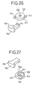
- FIGS. 26 through 31 A joint mechanism for joining structural members according to a further embodiment of the present invention is shown in FIGS. 26 through 31.
- the joint mechanism according to this embodiment is different from the joint mechanism according to the preceding embodiment in that a second engaging member 380 has a substantially T-shaped head 382 (see FIGS. 26 and 27), and the joint mechanism is used to join the structural members 20, 20a substantially perpendicularly to each other (see FIG. 28).
- the joint mechanism has a first engaging member 330 which is of a structure that is substantially identical to the first engaging member 330 according to the preceding embodiment.
- the head 382 of the second engaging member 380 is inserted from an end of the structural member 20a into one of the slots 22 therein.
- the head 382 may be turned about 90° so as to be mounted in the slot 22.
- the first engaging member 330 is inserted into the slot 22 such that the inner wall surface of the substantially circular hole 352 in the first engaging member 330 engages the curved surface of the hook 354 on an end of the second engaging member 380.
- the first engaging member 330 is retained in the substantially circular recess 334 in the slot 22, and the first engaging member 330 is inserted so as to align the fingers 344 with the slot 22, as indicated by the solid lines in FIG. 28. Since the circular hole 352 is off-center, the thickness of the wall extending around the circular hole 352 progressively varies from the smaller wall thickness to the greater wall thickness. When the first engaging member 330 is then angularly moved a predetermined angle, the fingers 344 of the first engaging member 330 are angularly displaced the predetermined angle as indicated by the broken lines in FIG. 28. As a result, as shown in FIG.
- joint mechanisms may be mounted respectively on upper and lower surfaces of the structural member 20 to firmly join the structural members 20, 20a with increased rigidity.
- FIGS. 32 through 35 show a joint mechanism for joining structural members according to a yet still further embodiment of the present invention.
- the joint mechanism according to this embodiment is used to join the structural members 20, 20a substantially perpendicularly to each other.
- the joint mechanism comprises first and second engaging members 384, 386, and a screw 388 having a tapered tip end 387 which is progressively smaller in diameter.
- the first engaging member 384 has a pair of fingers 392 disposed on an outer circumferential surface of a cylinder 390 and angularly spaced 180° from each other.
- the first engaging member 384 also has an internally threaded through hole 394 defined centrally therein.
- the second engaging member 386 has a substantially T-shaped head 396 and a flat plate 398 joined to the head 396 and having a tapered recess 400 remote from the head 396.
- the head 396 of the second engaging member 386 is inserted from an end of the structural member 20a into one of the slots 22 therein.
- the head 396 may be turned about 90° so as to be mounted in the slot 22.
- the other structural member 20 is placed substantially perpendicularly to the structural member 20a, and the flat plate 398 of the second engaging member 286 which projects from the structural member 20a is inserted into the slot 22 in the other structural member 20.
- the first engaging member 384 is inserted into the substantially circular recess 334 in the slot 22 in the structural member 20. Since the diameter of the substantially circular recess 334 is substantially the same as the diameter of the cylinder 390, the first engaging member 384 is retained in the recess 334. At this time, the first engaging member 384 is inserted so as to align the fingers 392 with the slot 22.
- the screw 388 is threaded into the internally threaded through hole 394 that is defined substantially centrally in the first engaging member 384.
- the first engaging member 384 is angularly moved in the direction indicated by the arrow in FIG. 33, bringing the fingers 392 into abutment against the wall surfaces of the enlarged portion 26 of the slot 26, whereupon the first engaging member 384 is retained in the slot 22, as indicated by the broken lines in FIG. 33.
- the tapered tip end 387 of the screw 388 engages in the tapered recess 400 in the flat plate 398 (see FIG. 34), pressing a slanting surface of the tapered recess 400.
- joint mechanisms may be mounted respectively on upper and lower surfaces of the structural member 20 to firmly join the structural members 20, 20a with increased rigidity.
- FIGS. 36 through 39 show a joint mechanism for joining structural members according to another embodiment of the present invention.
- the joint mechanism according to this embodiment is used to join the structural members 20, 20a substantially perpendicularly to each other.
- the joint mechanism has a pair of engaging members 408a, 408b each having a substantially T-shaped head 402 and a tapered member 406 including an internally threaded through hole 404 and a tapered surface 405 which is progressively smaller in diameter.
- the joint mechanism also has a substantially cylindrical sleeve 410 interposed between the engaging members 408a, 408b.
- the sleeve 410 has a pair of opposite tapered surfaces 412 each inclined at a slightly smaller angle than the tapered surface 405, and a through hole 114 defined therein between the opposite tapered surfaces 412.
- a bolt 416 extends through the through holes 404 in the engaging members 408a, 408b and the hole 414 in the sleeve 410.
- the hole 414 in the sleeve 410 has a diameter greater than the diameter of the bolt 416.
- the heads 402 of the engaging members 408a, 408b are inserted from an end of the structural member 20a into one of the slots 22 therein. Then, the other structural member 20 is placed substantially perpendicularly to the structural member 20a, and the tapered members 406 of the engaging members 408a, 408b are inserted respectively into the substantially circular recesses 334 in the slots 22 defined respectively in the upper and lower surfaces of the structural member 20.
- the sleeve 410 is fitted in a through hole that is defined transversely in the structural member 20 between the slots 22, the through hole having a diameter corresponding to the diameter of the sleeve 410.
- the bolt 416 is inserted into the tapered members 406 of the engaging members 408a, 408b and the sleeve 410 (see FIG. 38).
- the tapered surfaces 405 of the engaging members 408a, 408b are drawn into the sleeve 410 along the tapered surfaces 412 thereof.
- the heads 402 of the engaging members 408a, 408b exert forces tending to pull the structural member 20a in the direction indicated by the arrow X, joining and fixing the structural member 20a to the other structural member 20 (see FIG. 39).
- FIG. 40 shows the structural member 20 with a cover 23 of substantially channel-shaped cross section being mounted in one of the slots 22 which is used as a wiring passage for a lead 418.
- a pair of locking members 420a, 420b for locking the lead 418 is mounted in the slot 22 in the structural member 20, and a connector 422 with a plurality of terminals is connected to an end of the lead 418.
- the passage communication member is used simply to keep the passage in one of the structural members in communication with the passage in the other structural member.
- the first engaging member inserted in the recess in one of the structural members and the second engaging member retained in the slot in the other structural member are coupled to each other by the fastening member. Therefore, the structural members can easily be joined and fixed to each other. Consequently, the period of time that is required to join the structural members is greatly reduced, and the efficiency with which the structural members are joined is increased.
- the passage communication member and the first and second engaging members are simple in structure, they can be manufactured inexpensively on a mass-production basis.
- one of the joint mechanisms according to the present invention allows the structural members to be joined to each other for angular movement about the shaft. It is possible to join and fix the structural members to each other as they have been angularly moved a desired angle about the shaft.
- the first and second knuckles and the blocks can be attached to each other at a given angle established by the angle setting means. Therefore, the structural members can be joined and fixed to the each other as they have been twisted relatively to each other.
- the joint mechanism may be connected to angularly movable members such as door hinges, for example, and the angularly movable members may be angularly displaced about the shaft.
- the structural members can easily be joined to each other in line with or perpendicularly to each other by the first engaging member and the second engaging member which are of simple structure.
- the labor that is needed to join the structural members to each other can be reduced, the period of time that is required to joint the structural members to each other can be shortened, so that the efficiency of assembling the structural members can be increased.
- joint mechanisms for joining structural members according to the present invention may be used in a wide range of applications, e.g., to join structural members that are used in fluid pressure circuits and machines, components, apparatus, etc. which employ fluid pressure.
Applications Claiming Priority (10)
| Application Number | Priority Date | Filing Date | Title |
|---|---|---|---|
| JP168235/93 | 1993-07-07 | ||
| JP168233/93 | 1993-07-07 | ||
| JP16823293 | 1993-07-07 | ||
| JP16823393 | 1993-07-07 | ||
| JP16823293A JP3517433B2 (ja) | 1993-07-07 | 1993-07-07 | 構造部材用連結機構 |
| JP168232/93 | 1993-07-07 | ||
| JP16823593 | 1993-07-07 | ||
| JP16823593A JP3321253B2 (ja) | 1993-07-07 | 1993-07-07 | 構造部材用連結機構 |
| JP16823393A JP3517434B2 (ja) | 1993-07-07 | 1993-07-07 | 構造部材用連結機構 |
| PCT/JP1994/001098 WO1995002128A1 (fr) | 1993-07-07 | 1994-07-06 | Mecanisme de liaison pour elements de structure |
Publications (3)
| Publication Number | Publication Date |
|---|---|
| EP0802334A1 true EP0802334A1 (de) | 1997-10-22 |
| EP0802334A4 EP0802334A4 (de) | 1998-06-17 |
| EP0802334B1 EP0802334B1 (de) | 2002-05-02 |
Family
ID=27322975
Family Applications (1)
| Application Number | Title | Priority Date | Filing Date |
|---|---|---|---|
| EP94919857A Expired - Lifetime EP0802334B1 (de) | 1993-07-07 | 1994-07-06 | Verbindungsmechanismus für strukturelemente |
Country Status (7)
| Country | Link |
|---|---|
| US (3) | US5785359A (de) |
| EP (1) | EP0802334B1 (de) |
| KR (1) | KR100206510B1 (de) |
| AU (3) | AU679244B2 (de) |
| DE (1) | DE69430544T2 (de) |
| TW (1) | TW269661B (de) |
| WO (1) | WO1995002128A1 (de) |
Cited By (4)
| Publication number | Priority date | Publication date | Assignee | Title |
|---|---|---|---|---|
| EP0987450A1 (de) * | 1998-09-18 | 2000-03-22 | FMS Förder- und Montage-Systeme Schmalzhofer GmbH | Verbindungseinrichtung zum Verbinden von Profilstäben |
| FR2796875A1 (fr) * | 1999-07-29 | 2001-02-02 | A M G | Prehenseur modulaire |
| EP0919758A3 (de) * | 1997-11-26 | 2002-07-24 | Teseo S.R.L. | System von Elementen zur Herstellung einer zusammensetzbaren Rohrleitung aus extrudierten Rohrabschnitten |
| WO2009153273A1 (en) * | 2008-06-18 | 2009-12-23 | Kunstdünger Di Walzl Christian Snc | System consisting of sections and junction elements for forming load-bearing structures |
Families Citing this family (63)
| Publication number | Priority date | Publication date | Assignee | Title |
|---|---|---|---|---|
| US5785359A (en) | 1993-07-07 | 1998-07-28 | Smc Kabushiki Kaisha | Joint mechanism for structural members |
| US5806897A (en) * | 1995-10-03 | 1998-09-15 | Smc Corporation | Mechanism for attaching a fluid-related device to a device-attaching frame member |
| DE19604665A1 (de) * | 1996-02-09 | 1997-08-14 | Robert Soenser | Querverbinder für Profilstäbe |
| DE19641500C2 (de) * | 1996-10-09 | 2001-10-25 | Siegfried Aichner | Vorrichtung zum lösbaren Verbinden von Profilstäben |
| USD433120S (en) * | 1997-09-22 | 2000-10-31 | Smc Kabushiki Kaisha | Housing for a fluid pressure device |
| USD422075S (en) * | 1997-09-22 | 2000-03-28 | Smc Kabushiki Kaisha | Housing for a fluid pressure device |
| IT1303292B1 (it) * | 1998-10-30 | 2000-11-06 | Abb Ricerca Spa | Barra conduttrice per la distribuzione di energia elettrica. |
| JP2000154993A (ja) * | 1998-11-19 | 2000-06-06 | Denso Corp | 熱交換器 |
| DE29905687U1 (de) * | 1999-03-27 | 1999-07-08 | Sta Co Mettallerzeugnisse Gmbh | Trageinrichtung |
| EP1061272B1 (de) * | 1999-06-17 | 2003-03-19 | Zihlmann Engineering | Querverbindung von Profilstäben |
| DE19949926C1 (de) * | 1999-10-16 | 2001-05-10 | Christof Kaiser | Leitungssystem |
| GB0002644D0 (en) * | 2000-02-07 | 2000-03-29 | Fortress Interlocks Ltd | Interlock mechanisms |
| DE10016608B4 (de) * | 2000-04-04 | 2013-02-07 | Helmuth Kahl | Spannglied zum stirnseitigen Verbinden von Profilstäben |
| EP1205357A3 (de) * | 2000-10-24 | 2004-08-04 | Van den Born, Marcus Philippus Adrianus | Dachlastenträger bestehend aus Modulteilen |
| DE20107168U1 (de) * | 2001-04-26 | 2002-08-29 | Rixen Wolfgang | T-Verbindung zweier Profilstäbe |
| DE10135112B4 (de) * | 2001-07-19 | 2005-02-03 | Bark, Hannelore | Konstruktionssystem zur Herstellung von Baugruppen, wie Wand-,Boden-oder Deckenkonstruktionen |
| ITBO20010528A1 (it) * | 2001-09-03 | 2003-03-03 | Work Corp Inc S R L | Sistema di fissaggio per strutture modulari d'arredamento |
| EP1321592A1 (de) * | 2001-12-21 | 2003-06-25 | Paolo Manzi | Modulare Struktur für ein tragendes Rahmenwerk mit Profilkörpern und selbsttragenden Platten und Herstellungsverfahren dafür |
| DE20204618U1 (de) * | 2002-03-22 | 2003-07-31 | Lautenschlaeger Mepla Werke | Befestigungsanordnung von Möbelbeschlägen an Rahmenprofilen von platten- oder tafelförmigen Möbelteilen |
| ITTO20020421A1 (it) * | 2002-05-17 | 2003-11-17 | Comau Spa | Attrezzatura utilizzabile da un robot industriale per l'afferramento di pezzi o gruppi in lavorazione od assemblaggio,con struttura modulare |
| US6742311B2 (en) * | 2002-09-17 | 2004-06-01 | Expo Design International | Modular transportable floor decking system |
| US7444922B2 (en) * | 2003-01-28 | 2008-11-04 | Koganei Corporation | Fastening assembly, fastener, and fluid pressure cylinder unit |
| DE10318651A1 (de) * | 2003-04-24 | 2004-11-25 | Maytec Aluminium Systemtechnik Gmbh | Verbindungsvorrichtung zum Verbinden eines Profils mit einem weiteren Profil |
| US7195289B2 (en) * | 2004-03-26 | 2007-03-27 | Ingersoll-Rand Company | Fluid distribution system |
| DE502004004814D1 (de) * | 2004-07-09 | 2007-10-11 | Witte Horst Entwicklung | System zum Aufbau von Vorrichtungen zum Aufspannen von Werkstücken |
| US7775265B2 (en) * | 2004-09-15 | 2010-08-17 | Flex-A-Lite Consolidated, Inc. | Side tank design |
| CA2522005A1 (en) * | 2004-10-14 | 2006-04-14 | Hill-Rom Services, Inc. | Service head with accessory tracks |
| US20060236640A1 (en) * | 2005-03-15 | 2006-10-26 | Hung Si C | Structural framework having solid coupling |
| ITBO20050531A1 (it) * | 2005-08-10 | 2007-02-11 | Metal Work Srl | Sistema coordinato per il fissagio amovibile di elementi d'arredo alla struttura portante di una parete prefabbricata |
| CA2631060C (en) * | 2005-12-02 | 2014-01-21 | Keech Castings Australia Pty Limited | Fastening assembly |
| DE202007007888U1 (de) * | 2007-06-06 | 2008-10-09 | Horst Witte Entwicklungs- Und Vertriebs Kg | Element und System zum Aufbau von Vorrichtungen zum Aufspannen von Werkstücken |
| EP2113618A1 (de) * | 2008-04-30 | 2009-11-04 | Trenzametal, S.L. | Elemente zum Erstellen von Metallzaun und Geländer von herkömmlich vorgefertigten Profilstäben sowie deren Montage |
| US20090279941A1 (en) * | 2008-05-07 | 2009-11-12 | Michael Goldin | Adjustable joint for customizable furniture |
| US8354099B2 (en) | 2008-10-07 | 2013-01-15 | Ahava-Dead Sea Laboratories Ltd. | Skin-care compositions and uses thereof |
| US8100600B2 (en) * | 2008-10-23 | 2012-01-24 | Robert Bosch Gmbh | Pivoting connector assembly for connecting two members |
| DE102009039951B3 (de) * | 2009-08-27 | 2011-04-07 | Friedrich Lütze Gmbh & Co. Kg | Vorrichtung zum Befestigen und elektrischen Verdrahten einer Vielzahl von elektrischen Einheiten, insbesondere in einem Schaltschrank |
| US20110049311A1 (en) * | 2009-08-27 | 2011-03-03 | Friedrich Lutze Gmbh & Co. Kg | Device for fastening and electrically wiring a plurality of electrical units, particularly in a switching cabinet |
| DE102009040762B4 (de) * | 2009-09-09 | 2015-08-13 | Audi Ag | Modulares Tragsystem zur Fixierung von Bauteilen |
| AU2010219354A1 (en) * | 2009-10-20 | 2011-05-12 | Open Building Solutions Limited | Joinery connection assembly |
| JP4954314B2 (ja) * | 2010-05-14 | 2012-06-13 | 本田技研工業株式会社 | フランジの締結構造 |
| US20140197589A1 (en) * | 2011-01-05 | 2014-07-17 | Premysl-Uhrik LLC | Cross member systems and related methods |
| US8720707B2 (en) * | 2012-08-14 | 2014-05-13 | Institute Of Nuclear Energy Research, Atomic Energy Council | Frame using interior connectors for holding highly-concentrated solar cells |
| TW201411071A (zh) * | 2012-09-14 | 2014-03-16 | Atomic Energy Council | 大型太陽能電池模組結構 |
| US20140091510A1 (en) * | 2012-10-01 | 2014-04-03 | Lloyd, Gerstner & Partners | Fastening hardware holder with installation indicator |
| US8708169B1 (en) * | 2013-01-31 | 2014-04-29 | Shun-Teng Chen | Combination cabinet |
| ITRN20130012A1 (it) * | 2013-05-06 | 2014-11-07 | Sigma Di Evaristo Ambrogiani & C S Nc | Dispositivo per sollevamento, movimentazione e installazione di piastrelle sottili |
| FR3019751B1 (fr) * | 2014-04-11 | 2018-11-23 | Decathlon | Equipement de sport et kit comprenant un tel equipement de sport |
| USD773553S1 (en) | 2015-02-18 | 2016-12-06 | Stewart-Macdonald Manufacturing Company | Stringed instrument work station |
| AT516942B1 (de) * | 2015-04-28 | 2016-10-15 | Euler-Rolle Thomas Dipl Ing | Kühlerstation zum Anschluß eines Flüssigkeitskühlers |
| US20170030391A1 (en) * | 2015-07-31 | 2017-02-02 | Iconify Corp. | T-Slot Mechanism and Assembly for Use in Furniture Constructions |
| US10208892B1 (en) * | 2015-10-15 | 2019-02-19 | Jay G. Bianchini | Method and apparatus for creating a pre-fabricated kit for assembling and suspending a custom design frame for supporting a package in an elevated position |
| JP6758144B2 (ja) * | 2015-10-28 | 2020-09-23 | 株式会社荏原製作所 | 羽根車の製造方法 |
| KR101837375B1 (ko) | 2017-07-05 | 2018-04-19 | 김용래 | 프로파일 조립체 |
| KR101837378B1 (ko) | 2017-07-10 | 2018-04-19 | 김용래 | 프로파일 연결장치 |
| US10662650B2 (en) * | 2017-10-31 | 2020-05-26 | Vention Inc. | T-slot extrusion structure |
| EP3557084A1 (de) * | 2018-04-16 | 2019-10-23 | Schletter International B.V. | Verbindungselement zum verbinden von profilelementen |
| KR101986077B1 (ko) * | 2019-01-22 | 2019-06-26 | 주식회사 맥파이온 | 연결수단을 이용한 각재 연장장치 |
| DE102019115548A1 (de) * | 2019-05-07 | 2020-11-12 | Carl Zeiss Fixture Systems Gmbh | Profilstrang für die Errichtung von Trägervorrichtungen |
| WO2021022724A1 (zh) * | 2019-08-06 | 2021-02-11 | 京东方科技集团股份有限公司 | 一种框架及多屏互动显示设备 |
| KR102282496B1 (ko) * | 2019-12-09 | 2021-07-28 | 지상뉴매틱 주식회사 | 프로파일프레임 연결장치 |
| US11197542B2 (en) * | 2020-02-26 | 2021-12-14 | Huloit Storage Solutions Ltd. | Coupling system and construction including same |
| KR102416556B1 (ko) * | 2021-11-11 | 2022-07-05 | 참아름 주식회사 | 안정적인 수납구조를 포함하는 납골함 안치장치 |
| KR102416557B1 (ko) * | 2022-01-19 | 2022-07-05 | 참아름 주식회사 | 분해조립이 간편하고 구조적 안정성을 가지는 구조를 포함하는 납골함 안치장치 |
Citations (5)
| Publication number | Priority date | Publication date | Assignee | Title |
|---|---|---|---|---|
| NL6915210A (de) * | 1969-05-28 | 1970-12-01 | ||
| FR2260015A1 (en) * | 1974-02-05 | 1975-08-29 | Lahet Jean | Assembly piece for tubular structures - has slots on faces so it can be expanded within end of rectangular section tube |
| FR2653836A1 (fr) * | 1989-10-27 | 1991-05-03 | Lefur Jean Paul | Systeme d'assemblage de profiles creux et structure portante obtenue. |
| DE4211770A1 (de) * | 1991-05-02 | 1992-11-05 | Ratiotec Konstruktion Und Vert | Gestell aus profilstangen, die mittels verbindungselementen zusammengesetzt sind |
| CH683022A5 (de) * | 1991-03-21 | 1993-12-31 | Sury Wilhelm Von | Vorrichtung zum lösbaren Verbinden von mindestens teilweise plattenartigen Elementen zu einer Konstruktion. |
Family Cites Families (32)
| Publication number | Priority date | Publication date | Assignee | Title |
|---|---|---|---|---|
| US1602658A (en) * | 1922-06-07 | 1926-10-12 | Louis Germain Jr | Furniture joint |
| US2046942A (en) * | 1931-08-06 | 1936-07-07 | Robert A Goeller | Electrical connecter |
| US3560027A (en) * | 1967-02-20 | 1971-02-02 | Gra Tec Inc | Coupling assembly |
| US3538940A (en) * | 1967-09-15 | 1970-11-10 | Gra Tec Inc | Fitting assembly |
| JPS5114164Y2 (de) * | 1971-04-05 | 1976-04-15 | ||
| FR2257846B1 (de) * | 1973-07-03 | 1976-05-28 | Legris France Sa | |
| JPS50106903U (de) * | 1974-02-08 | 1975-09-02 | ||
| JPS5261323A (en) * | 1975-11-17 | 1977-05-20 | Akira Takase | Connection device of frame body |
| JPS5918501B2 (ja) * | 1976-04-06 | 1984-04-27 | 株式会社コマツパ−テイシヨン工業 | 無目材等の締めつけ金具 |
| JPS5348405U (de) * | 1976-09-29 | 1978-04-24 | ||
| US4458745A (en) * | 1979-02-02 | 1984-07-10 | Josef Gartner & Co. | Device for controlling the temperature of rooms in a building |
| JPS5824646B2 (ja) * | 1979-07-25 | 1983-05-23 | テクナル、アンテルナシヨナル、ソシエテ、アノニム | 型材組立用継手 |
| US4775259A (en) * | 1986-11-04 | 1988-10-04 | Benada Aluminum Of Florida, Inc. | Connector arrangement |
| DE8704548U1 (de) * | 1987-03-27 | 1988-07-21 | Robert Bosch Gmbh, 7000 Stuttgart, De | |
| US5090740A (en) * | 1989-03-01 | 1992-02-25 | Creager Richard F | Integral manifold |
| DE4016320C1 (de) * | 1990-05-21 | 1991-09-19 | Wolfgang Dipl.-Ing. Rixen | |
| GB9111659D0 (en) * | 1991-05-30 | 1991-07-24 | Kee Klamps Ltd | Tube joints |
| JP3135329B2 (ja) * | 1991-12-28 | 2001-02-13 | エスエムシー株式会社 | アクチュエータおよびその構造体 |
| JP3135330B2 (ja) * | 1991-12-28 | 2001-02-13 | エスエムシー株式会社 | アクチュエータおよびその構造体 |
| JP3301490B2 (ja) * | 1991-09-09 | 2002-07-15 | エスエムシー株式会社 | アクチュエータの構造体 |
| US5116299A (en) * | 1991-11-22 | 1992-05-26 | Kevin Kvols | Fastening system for members of a framework |
| US5190392A (en) * | 1991-11-26 | 1993-03-02 | The United States Of America As Represented By The Administrator Of The National Aeronautics And Space Administration | Robot-friendly connector |
| JP3135331B2 (ja) * | 1991-12-28 | 2001-02-13 | エスエムシー株式会社 | アクチュエータおよびその構造体 |
| DE9202301U1 (de) * | 1992-02-20 | 1993-06-17 | Geisen, Johannes, Dipl.-Ing., 2800 Bremen, De | |
| WO1994018104A1 (en) * | 1993-02-04 | 1994-08-18 | Beloit Technologies, Inc. | Reel for a papermaking machine |
| CA2089023A1 (en) * | 1993-02-08 | 1994-08-09 | Vittorio De Zen | Hollow members connector |
| US5785359A (en) | 1993-07-07 | 1998-07-28 | Smc Kabushiki Kaisha | Joint mechanism for structural members |
| US5433416A (en) * | 1994-01-10 | 1995-07-18 | Johnson; Ruben R. | Article support system |
| SE9402361L (sv) * | 1994-07-04 | 1995-06-26 | Foga System International Ab | Anordning vid koppling |
| SE9500344L (sv) * | 1995-01-31 | 1996-08-01 | Flexlink Systems Ab | Kopplingsanordning |
| JPH09296816A (ja) * | 1996-05-02 | 1997-11-18 | Smc Corp | 構造部材又は機械部品の相互結合装置又はその部品 |
| US6273635B1 (en) * | 1999-05-10 | 2001-08-14 | Swanson Systems, Inc. | Mounting fixture for a modular assembly machine |
-
1994
- 1994-07-06 US US08/964,314 patent/US5785359A/en not_active Expired - Fee Related
- 1994-07-06 EP EP94919857A patent/EP0802334B1/de not_active Expired - Lifetime
- 1994-07-06 WO PCT/JP1994/001098 patent/WO1995002128A1/ja active IP Right Grant
- 1994-07-06 KR KR1019960700039A patent/KR100206510B1/ko not_active IP Right Cessation
- 1994-07-06 DE DE69430544T patent/DE69430544T2/de not_active Expired - Fee Related
- 1994-07-06 AU AU70840/94A patent/AU679244B2/en not_active Ceased
- 1994-07-19 TW TW083106574A patent/TW269661B/zh active
-
1997
- 1997-09-18 AU AU38334/97A patent/AU693059B2/en not_active Ceased
- 1997-09-18 AU AU39198/97A patent/AU693060B2/en not_active Ceased
-
1998
- 1998-04-30 US US09/069,750 patent/US6059322A/en not_active Expired - Fee Related
-
2000
- 2000-03-29 US US09/537,312 patent/US6435755B1/en not_active Expired - Fee Related
Patent Citations (5)
| Publication number | Priority date | Publication date | Assignee | Title |
|---|---|---|---|---|
| NL6915210A (de) * | 1969-05-28 | 1970-12-01 | ||
| FR2260015A1 (en) * | 1974-02-05 | 1975-08-29 | Lahet Jean | Assembly piece for tubular structures - has slots on faces so it can be expanded within end of rectangular section tube |
| FR2653836A1 (fr) * | 1989-10-27 | 1991-05-03 | Lefur Jean Paul | Systeme d'assemblage de profiles creux et structure portante obtenue. |
| CH683022A5 (de) * | 1991-03-21 | 1993-12-31 | Sury Wilhelm Von | Vorrichtung zum lösbaren Verbinden von mindestens teilweise plattenartigen Elementen zu einer Konstruktion. |
| DE4211770A1 (de) * | 1991-05-02 | 1992-11-05 | Ratiotec Konstruktion Und Vert | Gestell aus profilstangen, die mittels verbindungselementen zusammengesetzt sind |
Non-Patent Citations (1)
| Title |
|---|
| See also references of WO9502128A1 * |
Cited By (6)
| Publication number | Priority date | Publication date | Assignee | Title |
|---|---|---|---|---|
| EP0919758A3 (de) * | 1997-11-26 | 2002-07-24 | Teseo S.R.L. | System von Elementen zur Herstellung einer zusammensetzbaren Rohrleitung aus extrudierten Rohrabschnitten |
| EP0987450A1 (de) * | 1998-09-18 | 2000-03-22 | FMS Förder- und Montage-Systeme Schmalzhofer GmbH | Verbindungseinrichtung zum Verbinden von Profilstäben |
| FR2796875A1 (fr) * | 1999-07-29 | 2001-02-02 | A M G | Prehenseur modulaire |
| WO2001008855A1 (fr) * | 1999-07-29 | 2001-02-08 | Amg | Prehenseur modulaire |
| WO2009153273A1 (en) * | 2008-06-18 | 2009-12-23 | Kunstdünger Di Walzl Christian Snc | System consisting of sections and junction elements for forming load-bearing structures |
| CN102076919B (zh) * | 2008-06-18 | 2013-07-10 | 孔思东设计有限公司 | 由型材和连接件组成的用于形成承载结构的系统 |
Also Published As
| Publication number | Publication date |
|---|---|
| AU3919897A (en) | 1997-12-18 |
| WO1995002128A1 (fr) | 1995-01-19 |
| DE69430544T2 (de) | 2002-12-05 |
| AU3833497A (en) | 1997-12-11 |
| US6435755B1 (en) | 2002-08-20 |
| AU7084094A (en) | 1995-02-06 |
| AU679244B2 (en) | 1997-06-26 |
| KR100206510B1 (ko) | 1999-07-01 |
| KR960704167A (ko) | 1996-08-31 |
| US6059322A (en) | 2000-05-09 |
| EP0802334B1 (de) | 2002-05-02 |
| AU693059B2 (en) | 1998-06-18 |
| US5785359A (en) | 1998-07-28 |
| TW269661B (de) | 1996-02-01 |
| DE69430544D1 (de) | 2002-06-06 |
| AU693060B2 (en) | 1998-06-18 |
| EP0802334A4 (de) | 1998-06-17 |
Similar Documents
| Publication | Publication Date | Title |
|---|---|---|
| EP0802334B1 (de) | Verbindungsmechanismus für strukturelemente | |
| US3881753A (en) | Fastener mechanism | |
| US4089613A (en) | Eccentric pin and bushing means for mounting misaligned components | |
| US7669806B2 (en) | Sway brace fitting | |
| JP3213367B2 (ja) | 構造部材の連結機構 | |
| US5864998A (en) | Modular structural members | |
| US5860315A (en) | Device for securing tools | |
| CA2175553A1 (en) | Integral joint and mounting assembly for suspended linear structures | |
| US5415383A (en) | Clamp arm with slip plane positioning | |
| US5769460A (en) | Connector for tubular guide rails | |
| US4753462A (en) | Adjustable tube clamping connector | |
| CN1108222C (zh) | 装有制动装置的液压缸的连接结构 | |
| US20040096290A1 (en) | Securing and holding assembly element | |
| EP0239781A1 (de) | Klemmverbindung zum Verbinden von sich schneidenden stabförmigen Körpern | |
| US20040258468A1 (en) | Fastening device and method for attaching an object to a support structure | |
| JPH06101787A (ja) | パイプ連結具 | |
| JP4308538B2 (ja) | 流体圧シリンダユニット | |
| EP0039615A1 (de) | Klemmverbindung | |
| JP2004232661A (ja) | 締結組立体および連結具 | |
| US20040169371A1 (en) | Speed lock pipe fitting | |
| JPH0515606Y2 (de) | ||
| JPH058053Y2 (de) | ||
| JPH03255281A (ja) | 流量調整弁相互の連結構造及び流量調整弁の固定部への取付構造 | |
| JPH0346079Y2 (de) | ||
| JPH0614083Y2 (ja) | 中空部材の結合構造 |
Legal Events
| Date | Code | Title | Description |
|---|---|---|---|
| PUAI | Public reference made under article 153(3) epc to a published international application that has entered the european phase |
Free format text: ORIGINAL CODE: 0009012 |
|
| 17P | Request for examination filed |
Effective date: 19960103 |
|
| AK | Designated contracting states |
Kind code of ref document: A1 Designated state(s): DE FR GB IT |
|
| A4 | Supplementary search report drawn up and despatched | ||
| AK | Designated contracting states |
Kind code of ref document: A4 Designated state(s): DE FR GB IT |
|
| 17Q | First examination report despatched |
Effective date: 19980904 |
|
| RA4 | Supplementary search report drawn up and despatched (corrected) |
Effective date: 19981123 |
|
| GRAG | Despatch of communication of intention to grant |
Free format text: ORIGINAL CODE: EPIDOS AGRA |
|
| GRAG | Despatch of communication of intention to grant |
Free format text: ORIGINAL CODE: EPIDOS AGRA |
|
| GRAH | Despatch of communication of intention to grant a patent |
Free format text: ORIGINAL CODE: EPIDOS IGRA |
|
| RAP1 | Party data changed (applicant data changed or rights of an application transferred) |
Owner name: SMC KABUSHIKI KAISHA |
|
| REG | Reference to a national code |
Ref country code: GB Ref legal event code: IF02 |
|
| GRAH | Despatch of communication of intention to grant a patent |
Free format text: ORIGINAL CODE: EPIDOS IGRA |
|
| GRAA | (expected) grant |
Free format text: ORIGINAL CODE: 0009210 |
|
| AK | Designated contracting states |
Kind code of ref document: B1 Designated state(s): DE FR GB IT |
|
| PG25 | Lapsed in a contracting state [announced via postgrant information from national office to epo] |
Ref country code: IT Free format text: LAPSE BECAUSE OF FAILURE TO SUBMIT A TRANSLATION OF THE DESCRIPTION OR TO PAY THE FEE WITHIN THE PRESCRIBED TIME-LIMIT;WARNING: LAPSES OF ITALIAN PATENTS WITH EFFECTIVE DATE BEFORE 2007 MAY HAVE OCCURRED AT ANY TIME BEFORE 2007. THE CORRECT EFFECTIVE DATE MAY BE DIFFERENT FROM THE ONE RECORDED. Effective date: 20020502 Ref country code: FR Free format text: LAPSE BECAUSE OF FAILURE TO SUBMIT A TRANSLATION OF THE DESCRIPTION OR TO PAY THE FEE WITHIN THE PRESCRIBED TIME-LIMIT Effective date: 20020502 |
|
| REG | Reference to a national code |
Ref country code: GB Ref legal event code: FG4D |
|
| REF | Corresponds to: |
Ref document number: 69430544 Country of ref document: DE Date of ref document: 20020606 |
|
| PG25 | Lapsed in a contracting state [announced via postgrant information from national office to epo] |
Ref country code: GB Free format text: LAPSE BECAUSE OF NON-PAYMENT OF DUE FEES Effective date: 20020802 |
|
| EN | Fr: translation not filed | ||
| PLBE | No opposition filed within time limit |
Free format text: ORIGINAL CODE: 0009261 |
|
| STAA | Information on the status of an ep patent application or granted ep patent |
Free format text: STATUS: NO OPPOSITION FILED WITHIN TIME LIMIT |
|
| GBPC | Gb: european patent ceased through non-payment of renewal fee |
Effective date: 20020802 |
|
| 26N | No opposition filed |
Effective date: 20030204 |
|
| PGFP | Annual fee paid to national office [announced via postgrant information from national office to epo] |
Ref country code: DE Payment date: 20060714 Year of fee payment: 13 |
|
| PG25 | Lapsed in a contracting state [announced via postgrant information from national office to epo] |
Ref country code: DE Free format text: LAPSE BECAUSE OF NON-PAYMENT OF DUE FEES Effective date: 20080201 |