EP0799643B1 - Vorrichtung zur Behandlung von Suspensionen - Google Patents
Vorrichtung zur Behandlung von Suspensionen Download PDFInfo
- Publication number
- EP0799643B1 EP0799643B1 EP97104850A EP97104850A EP0799643B1 EP 0799643 B1 EP0799643 B1 EP 0799643B1 EP 97104850 A EP97104850 A EP 97104850A EP 97104850 A EP97104850 A EP 97104850A EP 0799643 B1 EP0799643 B1 EP 0799643B1
- Authority
- EP
- European Patent Office
- Prior art keywords
- grinding
- reaction container
- basket
- designed
- agitating
- Prior art date
- Legal status (The legal status is an assumption and is not a legal conclusion. Google has not performed a legal analysis and makes no representation as to the accuracy of the status listed.)
- Expired - Lifetime
Links
- 239000000725 suspension Substances 0.000 title claims description 59
- 238000000227 grinding Methods 0.000 claims abstract description 157
- 238000006243 chemical reaction Methods 0.000 claims abstract description 107
- 238000012546 transfer Methods 0.000 claims description 9
- 239000007795 chemical reaction product Substances 0.000 claims description 8
- 238000011049 filling Methods 0.000 claims description 7
- 238000001816 cooling Methods 0.000 claims description 5
- 238000010438 heat treatment Methods 0.000 claims description 5
- 238000010992 reflux Methods 0.000 claims description 5
- 230000009969 flowable effect Effects 0.000 claims description 3
- 238000012216 screening Methods 0.000 claims 2
- 238000003756 stirring Methods 0.000 abstract description 17
- 230000000694 effects Effects 0.000 description 18
- 238000000034 method Methods 0.000 description 17
- 230000008569 process Effects 0.000 description 17
- 239000007787 solid Substances 0.000 description 14
- 238000013461 design Methods 0.000 description 6
- 239000000463 material Substances 0.000 description 5
- 239000000047 product Substances 0.000 description 5
- 230000015572 biosynthetic process Effects 0.000 description 4
- 239000006185 dispersion Substances 0.000 description 4
- 230000033001 locomotion Effects 0.000 description 4
- 230000008901 benefit Effects 0.000 description 3
- 239000007788 liquid Substances 0.000 description 3
- 238000009833 condensation Methods 0.000 description 2
- 230000005494 condensation Effects 0.000 description 2
- 238000010276 construction Methods 0.000 description 2
- 239000012263 liquid product Substances 0.000 description 2
- 238000012423 maintenance Methods 0.000 description 2
- 238000003801 milling Methods 0.000 description 2
- 210000000056 organ Anatomy 0.000 description 2
- 230000001737 promoting effect Effects 0.000 description 2
- 238000007789 sealing Methods 0.000 description 2
- 238000000926 separation method Methods 0.000 description 2
- 238000003860 storage Methods 0.000 description 2
- 206010010774 Constipation Diseases 0.000 description 1
- 229910000831 Steel Inorganic materials 0.000 description 1
- 238000009835 boiling Methods 0.000 description 1
- 239000003990 capacitor Substances 0.000 description 1
- 239000000919 ceramic Substances 0.000 description 1
- 230000008859 change Effects 0.000 description 1
- 239000011248 coating agent Substances 0.000 description 1
- 238000000576 coating method Methods 0.000 description 1
- 239000003086 colorant Substances 0.000 description 1
- LYKJEJVAXSGWAJ-UHFFFAOYSA-N compactone Natural products CC1(C)CCCC2(C)C1CC(=O)C3(O)CC(C)(CCC23)C=C LYKJEJVAXSGWAJ-UHFFFAOYSA-N 0.000 description 1
- 230000001419 dependent effect Effects 0.000 description 1
- 238000009826 distribution Methods 0.000 description 1
- 230000002349 favourable effect Effects 0.000 description 1
- 239000007789 gas Substances 0.000 description 1
- 239000011521 glass Substances 0.000 description 1
- 230000005484 gravity Effects 0.000 description 1
- 230000006872 improvement Effects 0.000 description 1
- 238000003780 insertion Methods 0.000 description 1
- 230000037431 insertion Effects 0.000 description 1
- 238000007689 inspection Methods 0.000 description 1
- 229910052751 metal Inorganic materials 0.000 description 1
- 239000002184 metal Substances 0.000 description 1
- 238000002156 mixing Methods 0.000 description 1
- TWNQGVIAIRXVLR-UHFFFAOYSA-N oxo(oxoalumanyloxy)alumane Chemical compound O=[Al]O[Al]=O TWNQGVIAIRXVLR-UHFFFAOYSA-N 0.000 description 1
- RVTZCBVAJQQJTK-UHFFFAOYSA-N oxygen(2-);zirconium(4+) Chemical compound [O-2].[O-2].[Zr+4] RVTZCBVAJQQJTK-UHFFFAOYSA-N 0.000 description 1
- 239000003973 paint Substances 0.000 description 1
- 239000002245 particle Substances 0.000 description 1
- 230000002093 peripheral effect Effects 0.000 description 1
- 239000000049 pigment Substances 0.000 description 1
- 239000013641 positive control Substances 0.000 description 1
- 238000002360 preparation method Methods 0.000 description 1
- 238000005086 pumping Methods 0.000 description 1
- 238000000518 rheometry Methods 0.000 description 1
- 238000005096 rolling process Methods 0.000 description 1
- 238000004062 sedimentation Methods 0.000 description 1
- 239000002904 solvent Substances 0.000 description 1
- 229910001220 stainless steel Inorganic materials 0.000 description 1
- 239000010935 stainless steel Substances 0.000 description 1
- 239000010959 steel Substances 0.000 description 1
- 239000000126 substance Substances 0.000 description 1
- 238000005496 tempering Methods 0.000 description 1
- 238000012549 training Methods 0.000 description 1
- 230000007704 transition Effects 0.000 description 1
- 238000011144 upstream manufacturing Methods 0.000 description 1
- 238000001238 wet grinding Methods 0.000 description 1
- 229910001928 zirconium oxide Inorganic materials 0.000 description 1
Images


Classifications
-
- B—PERFORMING OPERATIONS; TRANSPORTING
- B02—CRUSHING, PULVERISING, OR DISINTEGRATING; PREPARATORY TREATMENT OF GRAIN FOR MILLING
- B02C—CRUSHING, PULVERISING, OR DISINTEGRATING IN GENERAL; MILLING GRAIN
- B02C17/00—Disintegrating by tumbling mills, i.e. mills having a container charged with the material to be disintegrated with or without special disintegrating members such as pebbles or balls
- B02C17/16—Mills in which a fixed container houses stirring means tumbling the charge
- B02C17/168—Mills in which a fixed container houses stirring means tumbling the charge with a basket media milling device arranged in or on the container, involving therein a circulatory flow of the material to be milled
Definitions
- the invention relates to devices according to the Preambles of claims 1 and 2.
- the suspension to be treated is subject to circulation, in which, in addition to a dispersing device, a ball mill is involved. Via a feed pump, which at a suitable Place in the, the dispersing device with the ball mill connecting pipe is used, the suspension circulated within this cycle.
- a feed pump which at a suitable Place in the, the dispersing device with the ball mill connecting pipe is used, the suspension circulated within this cycle.
- grinding plants are used to process Paint colors and pigment pastes used.
- Comparable grinding plants are from US-A-5 497 948 and the EP-A-0 546 715 known.
- an agitator mill unit can be inserted through an opening on the top or This can be removed, the grinding system by a front and circumference perforated basket is formed.
- the basket is in known way filled with grinding media and there are itself above and below the basket conveying organs that are used to generate a suspension flow flowing axially through the basket globally are set up. As a result of the perforated peripheral walls the basket, however, is not a clear flow given for the suspension to be treated.
- reaction vessel It is outer jacket of the reaction vessel partially double-walled trained and to guide a cooling or heating medium set up - this only serves to remove the process heat unavoidable in comminution processes.
- the the lid closing the top of the reaction vessel can also omitted, so that these two known agitator units at least not designed for processes in which in addition, a gaseous or vaporous reaction product is obtained.
- a hydraulically lowerable agitator mill unit is the US-PS 3 892 364 removed, the reaction vessel is designed as an open system in which a to flow through using the suspension to be treated furnished cylindrical body containing grinding media is lowerable.
- the flow of the top down flowed through tubular body includes a simple top Overflow and is underside by a radial outflow characterized, whereby by means of attached to the tubular body, also radially extending impellers a a circuit given conveying member effecting within the container is.
- the rheological properties of the treating suspension can be known in this Device the quality of the flow within the container design differently.
- a wet grinding system in which within a rotationally symmetrical, double-walled Container an agitator mill unit and a Wet classifiers are provided.
- the container is because of it double-walled design either heated or coolable and designed for continuous operation, whereby a suspension is circulated within the same, from whose Solid content a fine grain fraction using the wet classifier separated and discharged as a finished product, whereas a remaining coarse grain fraction of a further grinding treatment is subjected.
- This publication discloses different configurations of the agitator mill unit, which are provided coaxially with the wet classifier can be, depending on the spatial arrangement the agitator mill unit relative to the wet classifier more or less pronounced guidance on the suspension is exercised.
- the agitator mill unit surrounds like a ring cylinder the wet classifier, so that a the grinding area of the mill unit radially to the outside continuous pressure gradient creating a flow field results.
- a dispersing device is known from DE 295 18 987 U1, which consists of one, inside a vertically arranged cylindrical container height-adjustable agitator ball mill exists below which - relative to that Containers in a fixed height position - one as a dissolver trained flow generating device is attached.
- the Agitator ball mill consists of a perforated sieve Housing in the shape of a toroidal, coaxial to the Axis of the container extending annular channel, the outer Periphery is kept at a distance from the inside of the housing and which encloses a central opening through which the drive shaft extending in the axial direction of the container of the dissolver is passed through.
- This drive shaft is on guided the upper end of the container in a hollow shaft, by means of which is inside the agitator ball mill, agitator formed by a system of annular discs is drivable.
- the agitator on the one hand and the dissolver on the other hand, are located outside of the container Drives can be driven - but it can also be a common one Drive for both devices can be provided.
- the Agitator ball mill is on bars inside the Container hung and there is another, the height adjustment serving drive device provided. While the dissolver predisperses the material to be dispersed causes, the agitator ball mill in a raised Position, i.e. is outside the dispersed material, is achieved by lowering the agitator ball mill in addition to a grinding effect fine dispersion also achieved.
- A is another embodiment Known grinding device, in which within a cylindrical reaction container is also cylindrical Insert body is located, which contains a grinding basket, the top and bottom end faces are perforated. Within the shaft penetrated by a stirring arm The grinding basket contains grinding media. About yourself within of the reaction vessel located below the grinding basket Conveyor becomes a circulatory flow within the reaction vessel In this way, it produces a suspension to be treated over the lower end face of the insert body in this and so that the grinding system is introduced and this on the top leaves again to then over the annulus between the Outside of the insert body and the inside of the vessel to flow towards the bottom and complete the cycle.
- the agitator inside the grinding basket on the one hand and that located below the grinding basket The funding body, on the other hand, each have their own drives.
- the insert body carrying the grinding system is circumferential and attached to the bottom of the reaction vessel.
- the Vessel also has a top inlet and one eccentrically arranged bottom outlet.
- Embodiment forms the reaction container with a a pump marked pipeline a circuit for the suspension to be treated.
- Find known milling device is due to the local Insert body from an improved positive guidance go out, which is exercised on the suspension to be treated becomes.
- the device shown is, however, exclusively based on the exercise of a crushing effect on the within a Suspended solid portion formed and especially not for the implementation of other, with a Crushing process, possibly related heterogeneous Reactions.
- the starting point of the invention is a reaction vessel, the one enclosed reaction space and the essential Components of the device, namely a grinding and a Mixing system included.
- the reaction vessel is pressure-resistant trained and thus equally for positive and negative pressure operation designed.
- the circulatory system, which is the one to be treated Suspension is subject to this is hermetically opposed reaction space sealed off from the outside, so this compact system is also performing heterogeneous reaction between solids, liquids and Gases within the reaction vessel allows without external reaction loops must be run.
- the grinding system comes with a fixed one, with the reaction vessel related grinding basket to use, the one Filling from grinding balls with a diameter of, for example 1 mm to 5 mm, which this for example with a degree of filling of about 80%.
- the choice of size and material of the grinding media or grinding balls depends on of the solids to be ground and the desired Grinding quality, especially the fineness of the suspension guided particles.
- the reaction container according to the invention is fundamental designed for discontinuous operation, the one multiple circulation of the suspension to be treated within one that provides the circuit containing the grinding system.
- the grinding basket is located in a tubular insert body according to the invention from the top of the reaction vessel in an opening arranged here is inserted sealingly. The quality of this seal depends on the process parameters the grinding process, especially taking into account of a pressure and vacuum operation as well as the properties of the selected suspension to be treated.
- the grinding system is located at one end of the insert body the same and it can be upstream and downstream with respect of the grinding basket, stirring or conveying elements are provided, thus expediently immediately adjacent to the grinding system.
- the fact that such conveyors within the tubular Insert body are arranged, there is a significantly improved conveying effect exerted on the suspension to be treated, exposed to intensive circulation in this way is.
- the task set out at the outset is alternative to a generic one Device also by the features of the claim 2 solved.
- the grinding basket is arranged in a bypass line, with stirring and / or on both sides of the grinding basket Funding bodies.
- the bypass line forms together with the reaction vessel a circuit for the treating suspension.
- the grinding basket is in a tube chamber be housed, whose cross-section compared to the rest Line sections of the bypass line is expanded so that a sufficient grinding volume is provided. This brings furthermore the advantage of a reduced within the grinding bed Flow rate, an increased dwell time and thus an improved grinding effect.
- To the pipe chamber close, for example, conical transition pipe sections and there is the mentioned stirring and / or conveying element outside of these pipe sections, so on a suitable one other place within the bypass line.
- the bypass line can consist of pipe elbows that are identical to one another the mentioned connection points of the reaction container are and with the interposition of flared Pipe sections the connection to the pipe or Create grinding chamber.
- the grinding and stirring system can correspond to the characteristics of the Claims 6 and 7 have common drive units - for however, both systems can also have separate drive units be provided.
- the latter has the advantage of a more extensive one Regulation of the essentials for the stirring and grinding process Parameters with themselves.
- stirrers for Use can according to the characteristics of claim 8 different types of stirrers for Use, e.g. Propeller, anchor or turbine stirrers.
- the choice of the specific type of stirrer used is made according to In accordance with its intended purpose, namely on the one hand a forced operation for the suspension to be treated and thus its circulation ensure and on the other hand within the Suspension to maintain a perfect dispersion state, so that solid deposits are prevented.
- There the usual operating speeds of relatively slow rotating Anchor, blade or grid stirrers are relatively different from those distinguish between fast rotating propeller and turbine stirrers, are dependent on the actually used Different drives required in individual cases or appropriate.
- the reaction vessel designed as a rotationally symmetrical vessel, within which the grinding and stirring system centered bez. coaxial or can also be arranged eccentrically.
- the grinding and stirring system is designed as a compact unit - these systems can also be separate from each other as part of the circulation within the reaction vessel be arranged.
- functional elements of the stirring system also in the immediate vicinity of the grinding system be arranged.
- Crucial for the distribution of these Functional elements along the circuit for the suspension are their rheological properties to which these elements are structurally adapted. So a flawless one Maintain the state of dispersion within the suspension and it must be ensured that this is within a forced control of the aforementioned circuit management experienced through the grinding bed of the grinding system.
- the axis runs of the grinding system parallel to the axis of the reaction container. This is a preferred orientation of this axis - but it is depending on the specific geometric design of the reaction vessel equally possible, the axis of the Grinding system in any angular arrangement to the axis of the reaction vessel to let go.
- the drive units are located according to the characteristics of claim 12 outside the reaction container, in particular outside of its reaction space. This requires the application suitable seals or the use of drives with Containment shell or magnetic drives in case of special requirements to the pressure resistance and the absence of leakage.
- the Drive units generally consist of motor-gear units, where adjusting gear for realizing a speed controllability can be used. Particularly advantageous are purely electrical speed controls, for example on the basis of a frequency control with input or Polyphase alternating current motors. Basically, however, come speed-controllable DC drives are also considered.
- the according to the features of claim 15 within the grinding basket Grinding disks are arranged with openings in the shape of slits, spirals, crosses, etc. and practice during the rotational movement has a driving effect on the grinding balls.
- claims 16 and 17 are based on the arrangement of the serving to guide the suspension through the grinding bed Openings of the grinding basket directed. These can be with a cylindrical formation of the same either in the end faces or in these end faces adjacent circumferential sections be arranged.
- the latter variant opened Favorable storage options for the drive shaft of the grinding or stirring system on the end faces designed as a circular plate as well as a larger screen area to reduce pressure losses.
- the insert body or the grinding basket with service openings for removing Grinding balls or equipped for the insertion of grinding balls.
- the reaction vessel is arranged, such Maintenance work involving the removal of grinding media as well related, relatively simple.
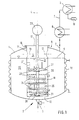
- Fig. 1 is a pressure-resistant, suitably stationary set up reaction vessel called. This is for determines a discontinuous operation and can over a not shown in the drawing, arranged in the upper area Inlet nozzle with the product to be treated, e.g. one Suspension are loaded. About one, at the lowest point of the Bottom 2 arranged organ 3 can flowable as a rule Product is discharged after treatment.
- The, regarding the axis 4 rotationally symmetrical reaction container 1 is loaded with the suspension up to a level 5, and it can the upper area 6 with an output line 7 for a gaseous reaction product, e.g. B. steam.
- a gaseous reaction product e.g. B. steam.
- the output line 7 first leads to a reflux condenser 8, in which a partial condensation takes place, one component of the steam condenses and into the reaction container 1 flowing back.
- the remaining vaporous product will finally condensed in a capacitor 9 and is due to the Position 10 as an optionally processable liquid product in front.
- Insert body 11 is a cylindrical, rotationally symmetrical to the axis 4, through the upper area 6 and into the reaction container 1 extending into and at a distance in front of Bottom 2 ending, having a front side 12 open on the underside Inscribed body.
- the mantle section of this Insert body 11 is in the vicinity of the upper region 6 a series of circular in cross-section, preferably in openings 13 arranged uniformly circumferential, what continuous connections between the interior 14 of the insert body 11 and between the outer sides and the facing inside of the reaction container 1 itself extend annular space 15.
- the insert body 11 is in the remaining sealing in one, in the upper region 6 of the reaction container 1 molded opening 16 is inserted and is on the top by a circular end plate 17 also sealed. This end plate 17 is for assembly and Inspection purposes preferably detachable on the insert body 11 attached.
- At 18 is a system of the outer surface of the reaction vessel 1 uniformly overlapping, guiding one Heat transfer medium serving half-pipe coils, which form a closed cable run, which in the drawing not shown with a suitable heat source or is also connected to a heat sink.
- This system 18 serves in accordance with what is happening within the reaction container 1 Process of heating or cooling the above Suspension.
- the reaction vessel can also be used with a double-walled jacket equipped for guiding a heat transfer medium his.
- the reaction vessel 1 including the above Systems 18 is otherwise - not shown in the drawing Way - with a heat-insulating coating provided so that the process temperature within the reaction vessel 1 largely independent of the ambient temperature is controllable.
- At 19 is a cylindrical, in the insert body 11, namely grinding basket arranged or inserted in its lower area referred to, which fills the cross section of the insert body 11 and its upper and lower end faces 20, 21 through Sieve plates are formed.
- the lower end face 21 extends at a short distance the underside end face 12 of the insert body 11.
- a drive shaft is designated, which with an outside of the reaction container 1 arranged drive unit 23 is operatively connected and thus through the end plate 17 extends through.
- the drive unit 23 any preferably speed-adjustable electric drive Find use, where a speed control via an adjusting gear or depending on the type of electric drive purely electrical, e.g. B. done via a frequency control can.
- the drive shaft 22 extending coaxially to the axis 4 extends by the way through both front sieve plates of the grinding basket 19 and is otherwise on this grinding basket and / or the insert body 11 in a suitable manner.
- Grinding balls for example, a diameter of 1 mm to Can have 5 mm and made of ceramic, z. B. on based on aluminum oxide or zirconium oxide, made of glass or made of metal, e.g. B. stainless steel or other steel can.
- These grinding balls 25 can, for example, approximately 80% of the Fill in the volume of the grinding basket 19.
- the holes made in the grinding disks 24 can pass through any geometric shapes, e.g. B. slots, spirals, crosses etc. are formed. Its purpose is the rotary motion the grinding disks 24, which are rotatably connected to the drive shaft 22 Are connected to transfer to these grinding balls 25, a Shredding effect on those moved by the grinding basket 19 Exercise solids and the flow resistance of the suspension by reducing the grinding bed.
- the reaction vessel 1 is designed to be pressure-resistant and can be used in the system 18 flowing heat transfer medium can be heated or cooled. It forms a hermetically sealed system within which Milling processes with simultaneous heterogeneous reactions feasible under vacuum or overpressure conditions are.
- the reaction vessel 1 forms a simple, compact one Reaction system that does not require external units and Can be used especially with rheologically difficult substance systems is.
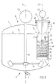
- one Grinding reactors are functional elements that correspond to those according to Fig. 1 also numbered accordingly, so that on a repeated description in this regard can be dispensed with can.
- the essential feature of the reaction container 1 shown in FIG. 2 is an insert body extending coaxially to the axis 4 28 ', within which, in turn, coaxial with axis 4 extending, a drive shaft 29 is mounted. With the drive shaft 29 are in a rotationally fixed connection, axially spaced grinding disks 24 in their nature and their intended use correspond to those according to FIG. 1.
- the insert body 28 ' has a conical underside Extension 30 on, and it is inside the insert body 28 ', namely its lower area a grinding basket 31, whose upper and lower end faces 32, 33 in turn according to Art are formed by sieve plates.
- a vessel which globally from the end faces 32 and 33 mentioned and corresponding ones
- the sides of the jacket or the strainer can structurally, however, only by the aforementioned End faces 32, 33 and otherwise through the walls of the insert body 28 'are formed.
- the one shown in Fig. 2 The embodiment forms the lower end face 33 at the same time the completion of the insert body 28 '. However, the latter is not mandatory.
- the space axially delimited by the end faces 32, 33 serves the purpose Picking up grinding balls 25. It is the one on the front of yours lower end at a distance above the lower end face 33, thus inside the grinding basket 31 ending drive shaft 29 hollow trained and serves as far as the coaxial inclusion of a another drive shaft 34, which extends through the entire length of the Drive shaft 29, thus also extends through the grinding basket 31 and on her, protruding from the lower end face 33 End carries a stirring element in the manner of an anchor stirrer 35.
- the impeller of this agitator engages around the lower end of the Insert body 28 at a distance and protrude into the, between the Outside of the insert body 28 'and the facing inside of the reaction vessel 1 existing annular space 36.
- 3 '' is another bar that acts as a baffle designated within the annulus 36, which are in immediate Extends near the impeller of the anchor stirrer 35.
- Anchor mixers are generally used at lower speeds operated as a propeller stirrer, so that in this embodiment 2 separate drives for these different stirrer types are provided.
- 1 and 2 is an essential feature of the exemplary embodiments, that the grinding basket is centered with respect to the reaction container 1 namely coaxially with respect to its axis 4.
- 3 is the one there Insert body 41 containing grinding basket 40 is cylindrical, however, eccentric with respect to the reaction container 1 arranged.
- the axis 42 of the insert body 41 extends however parallel to axis 4 of the reaction container 1. In the direction This axis 42 extends a drive shaft 43 which penetrates an upper end plate 44 of the insert body 41 and at its lower end inside the grinding basket 40 ends. She carries on her, which extends within the grinding basket Section in turn a series of grinding disks 24.
- the drive shaft 43 carries above the top Front 45 of the grinding basket 40 a propeller stirrer 46, the in coordination with the direction of rotation of the drive shaft 43 is designed such that it moves upwards in the direction of Arrows 28 creates directed suction within the suspension, which thus flows through the grinding bed.
- the drive shaft 43 stands outside the insert body 41 a drive unit 48, which is similar to the drive unit 23 (Fig. 1) can be formed.
- the insert body 41 is in an eccentrically arranged opening 49 of the upper region 6 of the reaction container 1 sealing used, which - as in the embodiment shown indicated - for example via an annular flange-like support one attached to the reaction container 1, coaxially the axis 42 extending pipe socket 50 can happen.
- At 52 is one, coaxial with the axis 4 of the reaction vessel 1 extending, at its lower, the floor 2 adjacent End a stirring element in the manner of a turbine stirrer 51 carrying Designated drive shaft.
- This is outside the reaction vessel 1 in connection with a drive unit 53, which can be designed similarly to the drive unit 48.
- a drive unit 53 which can be designed similarly to the drive unit 48.
- Corresponding the different stirrer types are also with this Design separate drives provided.
- the eccentric arrangement of the insert body 41 acts within of the reaction vessel 1 in fact like a baffle.
- the turbine stirrer 51 creates a flow field which the Suspension flow through the insert body 41 and thus that Grinding bed supports.
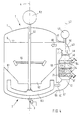
- the grinding basket there 54, the upper and lower end faces 45, 47 are in turn formed by sieve plates, in one cylindrical tube chamber 55 is arranged, which is outside of the reaction vessel 1 and the axis of which is, however extends parallel to its axis 4.
- the tube chamber 55 tapers themselves above and below, each following the End faces 45, 47 and is above pipe elbow 56, 57 and connecting piece 58, 59 with the interior of the reaction container 1 in a continuous connection.
- At 61 is a rotationally symmetrical to the axis 4, in the direction towards the bottom 2 tapered and funnel-like and in one central circular opening 62 ending insert.
- the drive shaft extends through the opening 62 52, below this opening 62 a like an anchor stirrer 63 and above this opening 62 in the manner of a turbine stirrer 64 trained funding body carries. Solids that deposit on the top of the insert 61, slide under Gravity on this surface down to over the opening 62 to reach the area of influence of the anchor stirrer 63. Because of the centrifugal force field generated by the latter In turn, solids accumulate in radially outer areas of the reaction vessel 1 and from here on the connecting piece 59 fed to the grinding bed.
- the anchor stirrer 63 thus supports the flow in the direction of arrows 60.
- An effect of the insert 61 is that it increases the suspension along the inner wall of the reaction container 1 in the area covered by the anchor stirrer 63 is, which is also the promotional effect in the direction arrows 60 improved.
- Essential feature of the embodiment shown in Fig. 5 is a grinding basket 65, the upper and lower end faces 66, 67 be formed by closed circular plates. However, there are the jacket sections adjoining the end faces 66, 67 68, 69 designed in the manner of a sieve, so that about these sections 68, 69 a suspension flow is possible.
- the Jacket sections 68, 69 each project in a rotationally symmetrical manner Arrangement in expanded cylindrical sections 70, 71 one Insert body into which one, in which Embodiment according to FIG. 1 corresponding way the drive shaft 22 extends with the - above and below of the grinding basket 65 - a propeller stirrer 27, 26 in a rotationally fixed Connection is established.
- the through the cylindrical sections 70, 71 and the grinding basket 65 formed insert body 11 'corresponds functionally, moreover, the insert body 11 according to FIG. 1.
Landscapes
- Engineering & Computer Science (AREA)
- Food Science & Technology (AREA)
- Crushing And Grinding (AREA)
- Disintegrating Or Milling (AREA)
- Chemical Treatment Of Metals (AREA)
- Vehicle Body Suspensions (AREA)
Description
Claims (23)
- Vorrichtung zur Behandlung von Suspensionen, mit einem Mahlsystem, welches ebenso wie ein Rührsystem in eine Kreislaufführung für die Suspensionen eingebunden ist, mit einem Reaktionsbehälter (1), innerhalb und/oder an welchemwobei der Boden (2) und die obere Abschlusswandung des Reaktionsbehälters (1) strukturell einander gleich, nämlich kugelflächen- oder kegelartig ausgebildet sind,eine bauliche Einheit mit diesem bildend - das Mahl- und das Rührsystem angeordnet sind, wobei der die Kreislaufführung zumindest teilweise aufnehmende Reaktionsbehälter (1) einschließlich des Mahl- und des Rührsystems als geschlossenes, für einen diskontinuierlichen Betrieb bestimmtes System ausgebildet sind, wobei im Boden (2) des Reaktionsbehälters (1) ein Austragsorgan für ein fließfähiges Reaktionsprodukt vorgesehen ist, wobei im oberen Bereich des Reaktionsbehälters (1) ein Zuführungsorgan für die zu behandelnde Suspension vorgesehen ist, wobei das Mahlsystem durch einen, von einer Antriebswelle (22,29,43) zentral durchdrungenen Mahlkorb (19,31,40,54,65) gebildet ist, wobei der Innenraum des Mahlkorbes nach Maßgabe eines wählbaren Füllungsgrades mit Mahlkörpern, z.B. Mahlkugeln (25) gefüllt ist, wobei der Mahlkorb mit eingangs- und ausgangsseitigen, einen Durchtritt der Mahlkörper unterbindenden, für einen Durchfluss der zu behandelnden Suspensionen bestimmten Öffnungen ausgerüstet ist und wobei der Reaktionsbehälter (1) als druckfestes Gefäß ausgebildet ist,
dadurch gekennzeichnetdass der Mahlkorb (19,31,40,65) in einem global rohrförmigen Einsatzkörper (11,28',41,11') angeordnet ist,dass innerhalb des Einsatzkörpers (11,28',41,11') ein Rühr- und/oder Förderorgan angeordnet ist,dass der Einsatzkörper (11,28',41,11') in eine oberseitige Öffnung (16,48) des Reaktionsbehälters (1) dichtend eingesetzt und oberseitig durch eine Abschlussplatte (17,44), welche der Führung der Antriebswelle (22,29,43) des Mahl- und/oder Rührsystems dient, dichtend abgeschlossen ist unddass die unterseitige Stirnseite des Einsatzkörpers (11,28',41,11') die Eintrittsöffnung und oberseitige, radial orientierte Öffnungen (13) des Einsatzkörpers die Austrittsöffnung für die zu behandelnde Suspension oder umgekehrt bilden. - Vorrichtung zur Behandlung von Suspensionen, mit einem Mahlsystem, welches ebenso wie ein Rührsystem in eine Kreislaufführung für die Suspensionen eingebunden ist, mit einem Reaktionsbehälter (1), innerhalb und/oder an welchem - eine bauliche Einheit mit diesem bildend - das Mahl- und das Rührsystem angeordnet sind, wobei der die Kreislaufführung zumindest teilweise aufnehmende Reaktionsbehälter (1) einschließlich des Mahl- und des Rührsystems als geschlossenes, für einen diskontinuierlichen Betrieb bestimmtes System ausgebildet sind, wobei im Boden (2) des Reaktionsbehälters (1) ein Austragsorgan für ein fließfähiges Reaktionsprodukt vorgesehen ist, wobei im oberen Bereich des Reaktionsbehälters (1) ein Zuführungsorgan für die zu behandelnde Suspension vorgesehen ist, wobei das Mahlsystem durch einen, von einer Antriebswelle (22,29,43) zentral durchdrungenen Mahlkorb (19,31,40,54,65) gebildet ist, wobei der Innenraum des Mahlkorbes nach Maßgabe eines wählbaren Füllungsgrades mit Mahlkörpern, z. B. Mahlkugeln (25) gefüllt ist, wobei der Mahlkorb mit eingangs- und ausgangsseitigen, einen Durchtritt der Mahlkörper unterbindenden, für einen Durchfluss der zu behandelnden Suspensionen bestimmten Öffnungen ausgerüstet ist und wobei der Reaktionsbehälter (1) als druckfestes Gefäß ausgebildet ist,
wobei der Mahlkorb (54) in einer Bypassleitung, diese querschnittsmäßig ausfüllend angeordnet ist,
wobei innerhalb der Bypassleitung ein Rühr- und/oder Förderorgan angeordnet ist,
wobei der Mahlkorb (54) in einer Rohrkammer (55) angeordnet ist, die sich koaxial zu der Achse des Mahlsystems erstreckt,
wobei die Bypassleitung einschließlich der Rohrkammer (55) ein Element der Kreislaufführung für die Suspensionen bildet,
dadurch gekennzeichnet,dass der Boden (2) und die obere Abschlusswandung des Reaktionsbehälters (1) strukturell einander gleich, nämlich kugelflächen- oder kegelartig ausgebildet sind,dass die Rohrkammer (55) eingangs- und ausgangsseitig über sich verjüngende Rohrabschnitte in sich anschließende Strukturelemente der Bypassleitung übergeht,dass der eine Anschlusspunkt der Bypassleitung an dem Reaktionsbehälter mit Abstand zum Bodenbereich des Reaktionsbehälters (1) angeordnet ist und dass der andere Anschlusspunkt der Bypassleitung an dem Reaktionsbehälter mit Abstand von der oberen Abschlusswandung des Reaktionsbehälters (1) angeordnet ist, wobei diese Anschlusspunkte durch Anschlußstutzen gebildet sind. - Vorrichtung nach Anspruch 1 oder 2,
dadurch gekennzeichnet,dass an dem Reaktionsbehälter (1) eine Austragsleitung (7) für ein dampfförmiges Reaktionsprodukt angeordnet ist unddass im Zuge der Austragsleitung (7) zumindest ein Rückflusskühler (8) angeordnet ist. - Vorrichtung nach Anspruch 3,
dadurch gekennzeichnet,dass im Zuge der Austragsleitung (7) ferner ein Kondensator (9) angeordnet ist. - Vorrichtung nach einem der vorangegangenen Ansprüche 1 bis 4,
dadurch gekennzeichnet,dass der Mahlkorb (19,31,40,54,65) rotationssymmetrisch bezüglich der Achse (4,42) des Mahlsystems ausgebildet ist. - Vorrichtung nach einem der Ansprüche 1 bis 5,
dadurch gekennzeichnet,dass für das Mahl- und das Rührsystem eine gemeinsame Antriebseinheit (23,38) vorgesehen ist. - Vorrichtung nach einem der vorangegangenen Ansprüche 1 bis 5,
dadurch gekennzeichnet,dass für das Mahl- und das Rührsystem voneinander getrennte Antriebseinheiten vorgesehen sind. - Vorrichtung nach einem der vorangegangenen Ansprüche 1 bis 7,
dadurch gekennzeichnet,dass als Rühr- und/oder Förderorgan Propellerrührer (26,27,37,46), Ankerrührer (35,63) oder Turbinenrührer (51,64) vorgesehen sind. - Vorrichtung nach einem der Ansprüche 1 oder 3 bis 8,
dadurch gekennzeichnet,dass der Reaktionsbehälter (1) als ein zu einer Achse (4) rotationssymmetrisches Gefäß ausgestaltet ist,dass das Mahl- und das Rührsystem als eine zu dieser Achse (4) rotationssymmetrische Baueinheit ausgebildet sind unddass diese Baueinheit unter Belassung eines diese außenseitig umgebenden Raumes (15,36) innerhalb des Reaktionsbehälters (1) angeordnet ist. - Vorrichtung nach einem der Ansprüche 1 oder 3 bis 8,
dadurch gekennzeichnet,dass der Reaktionsbehälter (1) als ein zu einer Achse (4) rotationssymmetrisches Gefäß ausgebildet ist,dass das Mahlsystem als eine zu dieser Achse (4) exzentrisch angeordnete Baueinheit ausgebildet ist unddass die das Rührsystem bildenden Bauelemente sowohl innerhalb als auch außerhalb der genannten Baueinheit angeordnet sind. - Vorrichtung nach Anspruch 10,
dadurch gekennzeichnet,dass die Achse (42) des Mahlsystems parallel zur Achse (4) des Reaktionsbehälters verläuft. - Vorrichtung nach einem der vorangegangenen Ansprüche 1 bis 11,
dadurch gekennzeichnet,dass die Antriebseinheiten (23,38,39,48,53) außerhalb des Reaktionsbehälters (1) angeordnet sind,dass die Antriebswellen (22,29,34,43,52) des Mahl- und/oder Rührsystems über druckfeste Wandungsdurchführungen des Reaktionsbehälters mit den Antriebseinheiten (23,38,39,48,53) in Verbindung stehen unddass die Antriebseinheiten (23,38,39,48,53) drehzahlregelbar ausgebildet sind. - Vorrichtung nach einem der vorangegangenen Ansprüche 1 bis 12,
dadurch gekennzeichnet,dass eine Kühl- oder Beheizungseinrichtung durch eine zur Führung eines Wärmeträgermediums bestimmte und ausgestaltete Doppelwandigkeit des Reaktionsbehälters (1) gebildet ist,wobei das Wärmeträgermedium in einem eine Wärmesenke und/oder eine Wärmequelle enthaltenden Kreislauf geführt ist. - Vorrichtung nach einem der vorangegangenen Ansprüche 1 bis 12,
dadurch gekennzeichnet,dass eine Kühl- oder Beheizungseinrichtung durch eine zur Führung eines Wärmeträgermediums bestimmte, außenseitig an dem Reaktionsbehälter (1) angebrachte Rohrschlangenanordnung gebildet ist,wobei das Wärmeträgermedium in einem eine Wärmesenke und/oder eine Wärmequelle enthaltenden Kreislauf geführt ist. - Vorrichtung nach einem der vorangegangenen Ansprüche 1 bis 14,
dadurch gekennzeichnet,dass mit der Antriebswelle (22,29,43) - axial voneinander beabstandet und innerhalb des Mahlkorbes (19,31,40,54,65) angeordnet - mehrere Mahlscheiben (24) in drehfester Verbindung stehen. - Vorrichtung nach Anspruch 1,
dadurch gekennzeichnet,dass die genannten Öffnungen des Mahlkorbes durch die als Siebplatten ausgebildeten Stirnseiten (20,21;32,33;45,47) des Mahlkorbes (19,31,40,54) gebildet werden. - Vorrichtung nach Anspruch 1,
dadurch gekennzeichnet,dass die genannten Öffnungen durch endseitige, als Siebabschnitte ausgebildete Umfangsabschnitte des Mahlkorbes (65) gebildet werden. - Vorrichtung nach einem der Ansprüche 1 oder 3 bis 17,
dadurch gekennzeichnet,dass der Mahlkorb (19,31,40,65) an dem der unterseitigen Stirnseite (12) benachbarten Ende des Einsatzkörpers (11,28',41,11') angeordnet ist und sich axial über eine Teillänge desselben erstreckt. - Vorrichtung nach Anspruch 2,
dadurch gekennzeichnet,dass die Antriebswelle (43) des Mahlsystems dichtend durch eine Wandungsöffnung der Bypassleitung hindurchgeführt ist. - Vorrichtung nach Anspruch 19,
dadurch gekennzeichnet,dass das Rühr- und/oder Förderorgan außerhalb der sich verjüngenden Rohrabschnitte angeordnet ist. - Vorrichtung nach einem der Ansprüche 1 oder 3 bis 18,
dadurch gekennzeichnet,dass die Stirnseite des Einsatzkörpers (11,28',41,11') mit Abstand zum Bodenbereich des Reaktionsbehälters (1) angeordnet ist unddass die Öffnungen (13) des Einsatzkörpers (11,28',41,11') mit Abstand von der oberen Abschlusswandung des Reaktionsbehälters angeordnet sind. - Vorrichtung nach einem der vorangegangenen Ansprüche 1 bis 21,
dadurch gekennzeichnet,dass innerhalb des Reaktionsbehälters (1) wenigstens ein eine trichterartige, eine zentrale Öffnung (62) aufweisender, den Innenraum des Reaktionsbehälters (1) in zwei über die genannte Öffnung (62) in einer, einen Suspensionsdurchtritt ermöglichenden Verbindung stehende Kammern unterteilender Einsatz (61) angeordnet ist,wobei die Antriebswelle (52) durch die Öffnung (62) hindurchgeführt ist undwobei in den Kammern unterschiedliche Rührorgane (63,64) mit der Antriebswelle (52) in drehfester Verbindung stehen. - Vorrichtung nach einem der vorangegangenen Ansprüche 1 bis 22,
dadurch gekennzeichnet,dass der Einsatzkörper (11,28',41,11') bzw. der Mahlkorb (19,31,40,65) mit Entnahme- und Befüllöffnungen für die Mahlkörper ausgerüstet ist.
Applications Claiming Priority (2)
| Application Number | Priority Date | Filing Date | Title |
|---|---|---|---|
| DE19613366 | 1996-04-03 | ||
| DE19613366A DE19613366A1 (de) | 1996-04-03 | 1996-04-03 | Vorrichtung zur Behandlung von Suspensionen |
Publications (2)
| Publication Number | Publication Date |
|---|---|
| EP0799643A1 EP0799643A1 (de) | 1997-10-08 |
| EP0799643B1 true EP0799643B1 (de) | 2002-01-16 |
Family
ID=7790394
Family Applications (1)
| Application Number | Title | Priority Date | Filing Date |
|---|---|---|---|
| EP97104850A Expired - Lifetime EP0799643B1 (de) | 1996-04-03 | 1997-03-21 | Vorrichtung zur Behandlung von Suspensionen |
Country Status (5)
| Country | Link |
|---|---|
| US (1) | US5934579A (de) |
| EP (1) | EP0799643B1 (de) |
| JP (1) | JP3527612B2 (de) |
| AT (1) | ATE211949T1 (de) |
| DE (2) | DE19613366A1 (de) |
Families Citing this family (37)
| Publication number | Priority date | Publication date | Assignee | Title |
|---|---|---|---|---|
| FR2777807B1 (fr) * | 1998-04-24 | 2000-06-16 | Gerard Rousselle | Turbine de mise en circulation d'une masse de matiere de viscocite determinee |
| US6814319B2 (en) * | 2000-12-06 | 2004-11-09 | Pharmacia & Upjohn Company | Laboratory scale milling process |
| CN1533304A (zh) * | 2001-05-23 | 2004-09-29 | 纳幕尔杜邦公司 | 高压介质磨 |
| EP1392441B1 (de) * | 2001-06-05 | 2008-07-23 | Elan Pharma International Limited | Mahlvorrichtung und verfahren zu deren betrieb |
| US20050258288A1 (en) * | 2003-11-26 | 2005-11-24 | E. I. Du Pont De Nemours And Company | High pressure media milling system and process of forming particles |
| DE102005020460B4 (de) * | 2005-04-29 | 2007-03-29 | Ika - Werke Gmbh & Co. Kg | Rühr- oder Dispergiervorrichtung |
| US9061477B2 (en) | 2007-12-13 | 2015-06-23 | Kitaru Innovations Inc. | Method and apparatus for making, shipping and erecting boxes |
| US20090319395A1 (en) * | 2007-12-13 | 2009-12-24 | Kitaru Innovations Inc. | Method of selling and shipping a product utilizing the internet |
| US8047459B2 (en) * | 2008-06-28 | 2011-11-01 | D Errico Edward | Co-axial basket mill and method of use |
| DE102008063718B4 (de) * | 2008-12-19 | 2010-09-16 | Kba-Metronic Aktiengesellschaft | Tintentank mit Mahlwerk |
| JP5599573B2 (ja) | 2009-04-10 | 2014-10-01 | 出光興産株式会社 | 固体電解質粒子からなるガラス及びリチウム電池 |
| DE102009034607A1 (de) * | 2009-07-24 | 2011-01-27 | Evonik Goldschmidt Gmbh | Neuartige Siliconpolyethercopolymere und Verfahren zu deren Herstellung |
| DE102010001350A1 (de) | 2010-01-29 | 2011-08-04 | Evonik Goldschmidt GmbH, 45127 | Neuartige lineare Polydimethylsiloxan-Polyether-Copolymere mit Amino- und/oder quaternären Ammoniumgruppen und deren Verwendung |
| DE102010053484A1 (de) * | 2010-12-04 | 2012-06-06 | Netzsch-Feinmahltechnik Gmbh | Dynamisches Element für die Trenneinrichtung einer Rührwerkskugelmühle |
| DE102011076019A1 (de) | 2011-05-18 | 2012-11-22 | Evonik Goldschmidt Gmbh | Alkoxylierungsprodukte und Verfahren zu ihrer Herstellung mittels DMC-Katalysatoren |
| KR101163481B1 (ko) | 2012-02-20 | 2012-07-18 | 이건의 | 필터 및 씰링이 필요없는 습식 분쇄장치 |
| CN102631969A (zh) * | 2012-03-30 | 2012-08-15 | 中国科学院东北地理与农业生态研究所 | 土壤或植物样品撞碎机 |
| US9304066B2 (en) | 2012-04-11 | 2016-04-05 | Stat-Diagnostica & Innovation S.L. | Fluidically integrated rotary bead beader |
| US8376252B1 (en) * | 2012-09-13 | 2013-02-19 | Hockmeyer Equipment Corp. | Producing nanometer-range particle dispersions |
| DE102013208328A1 (de) | 2013-05-07 | 2014-11-13 | Evonik Industries Ag | Polyoxyalkylene mit seitenständigen langkettigen Acyloxyresten und Verfahren zu ihrer Herstellung mittels DMC-Katalysatoren |
| DE102013111762A1 (de) | 2013-07-08 | 2015-01-08 | Netzsch-Feinmahltechnik Gmbh | Rührwerkskugelmühle mit Axialkanälen |
| CN103769276A (zh) * | 2014-01-22 | 2014-05-07 | 武汉科技大学 | 一种精细控温研磨装置 |
| DE102014209408A1 (de) | 2014-05-19 | 2015-11-19 | Evonik Degussa Gmbh | Ethoxylatherstellung unter Verwendung hoch aktiver Doppelmetallcyanid-Katalysatoren |
| CN105854688B (zh) * | 2015-01-20 | 2018-09-28 | 国泰涂料油墨股份有限公司 | 研磨混合机及研磨混合装置 |
| ES2676430T3 (es) | 2015-11-11 | 2018-07-19 | Evonik Degussa Gmbh | Polímeros curables |
| EP3321304B1 (de) | 2016-11-15 | 2019-06-19 | Evonik Degussa GmbH | Mischungen zyklischer-verzweigter siloxane vom d/t-typ und deren folgeprodukte |
| EP3415548B1 (de) | 2017-06-13 | 2020-03-25 | Evonik Operations GmbH | Verfahren zur herstellung sic-verknüpfter polyethersiloxane |
| EP3415547B1 (de) | 2017-06-13 | 2020-03-25 | Evonik Operations GmbH | Verfahren zur herstellung sic-verknüpfter polyethersiloxane |
| EP3438158B1 (de) | 2017-08-01 | 2020-11-25 | Evonik Operations GmbH | Herstellung von sioc-verknüpften polyethersiloxanen |
| EP3467006B1 (de) | 2017-10-09 | 2022-11-30 | Evonik Operations GmbH | Mischungen zyklischer-verzweigter siloxane vom d/t-typ und deren folgeprodukte |
| CN109939790A (zh) * | 2017-12-21 | 2019-06-28 | 深圳市微纳达智能设备有限公司 | 一种立式无筛网出料介质搅拌磨 |
| EP3611214A1 (de) | 2018-08-15 | 2020-02-19 | Evonik Operations GmbH | Sioc-verknüpfte, lineare polydimethylsiloxan-polyoxyalkylen-blockcopolymere |
| EP3611215A1 (de) | 2018-08-15 | 2020-02-19 | Evonik Operations GmbH | Verfahren zur herstellung acetoxygruppen-tragender siloxane |
| CN110773034B (zh) * | 2019-11-18 | 2021-12-07 | 华东交通大学 | 一种可实现均匀混料的颗粒/介质悬浮液循环搅拌供给装置 |
| CN111620707B (zh) * | 2020-06-09 | 2022-07-08 | 江苏脒诺甫纳米材料有限公司 | 一种复合锆英粉的制备方法 |
| GB202105249D0 (en) * | 2021-04-13 | 2021-05-26 | Sharon Tal | Device and method of grating payload substance combined with grinding and stirring function |
| RU206931U1 (ru) * | 2021-07-05 | 2021-10-01 | Федеральное государственное бюджетное научное учреждение «Федеральный научный центр пищевых систем им. В.М. Горбатова» РАН | Устройство для тонкого измельчения сыпучих материалов |
Family Cites Families (11)
| Publication number | Priority date | Publication date | Assignee | Title |
|---|---|---|---|---|
| GB489171A (en) * | 1937-01-19 | 1938-07-19 | William Langsdorf | Improvements in paint and like mixing and grinding machines |
| US3998938A (en) * | 1971-07-27 | 1976-12-21 | Union Process International, Inc. | Method and apparatus for grinding particulate solids |
| GB1456606A (en) * | 1973-05-15 | 1976-11-24 | Szegvari A | Method and apparatus for grinding particulate solids |
| US3892364A (en) * | 1974-05-09 | 1975-07-01 | Henry L Lomasney | Apparatus and method for dispersing and comminuting the solid in a solid-liquid mixture |
| WO1989011911A1 (fr) * | 1988-06-10 | 1989-12-14 | Kubota, Ltd. | Procede de broyage et de pulverisation |
| DE3838981A1 (de) * | 1988-11-18 | 1990-05-23 | Eirich Walter | Ruehrwerkskugelmuehle |
| US5184783A (en) * | 1991-12-03 | 1993-02-09 | Hockmeyer Equipment Corp. | Basket media mill and method |
| JP2575498Y2 (ja) * | 1993-01-08 | 1998-06-25 | 三井鉱山株式会社 | 粉砕機の構造 |
| DE4425906C2 (de) * | 1994-07-21 | 1997-02-06 | Netzsch Erich Holding | Naßmahlsystem |
| US5497948A (en) * | 1995-05-16 | 1996-03-12 | Hockmeyer Equipment Corp. | Basket media mill with extended impeller |
| DE29518987U1 (de) * | 1995-09-09 | 1996-02-15 | Getzmann, Hermann, 51580 Reichshof | Dispergiervorrichtung |
-
1996
- 1996-04-03 DE DE19613366A patent/DE19613366A1/de not_active Withdrawn
-
1997
- 1997-03-21 AT AT97104850T patent/ATE211949T1/de not_active IP Right Cessation
- 1997-03-21 DE DE59705981T patent/DE59705981D1/de not_active Expired - Lifetime
- 1997-03-21 EP EP97104850A patent/EP0799643B1/de not_active Expired - Lifetime
- 1997-04-03 JP JP08475697A patent/JP3527612B2/ja not_active Expired - Fee Related
- 1997-04-03 US US08/832,452 patent/US5934579A/en not_active Expired - Lifetime
Also Published As
| Publication number | Publication date |
|---|---|
| DE19613366A1 (de) | 1997-10-09 |
| JP3527612B2 (ja) | 2004-05-17 |
| US5934579A (en) | 1999-08-10 |
| DE59705981D1 (de) | 2002-02-21 |
| EP0799643A1 (de) | 1997-10-08 |
| JPH1028891A (ja) | 1998-02-03 |
| ATE211949T1 (de) | 2002-02-15 |
Similar Documents
| Publication | Publication Date | Title |
|---|---|---|
| EP0799643B1 (de) | Vorrichtung zur Behandlung von Suspensionen | |
| EP0058886B1 (de) | Rührwerksmühle | |
| EP0214145B1 (de) | Dispergierverfahren und rührwerksmühle zu seiner durchführung | |
| EP0700722A1 (de) | Rührwerksmühle | |
| DE69506094T2 (de) | Verfahren und Vorrichtung zum Rühren von Behandlungsflüssigkeit | |
| DE4128074A1 (de) | Ruehrwerkskugelmuehle | |
| DE2020649A1 (de) | Vorrichtung zum Deagglomerieren und zum Dispergieren von in agglomerierter Form in einem fluessigen Traeger vorliegenden Festkoerperteilchen | |
| DE1237415B (de) | Verfahren zum Entagglomerieren und Dispergieren von Feststoffteilchen in Fluessigkeiten | |
| EP0913200B1 (de) | Rührwerksmühle | |
| DE1652151A1 (de) | Verfahren und Vorrichtung zur Oberflaechenbehandlung von Werkstuecken | |
| WO1991006364A1 (de) | Vorrichtung zur bewegung von feststoffpartikeln | |
| DE2428359A1 (de) | Verfahren und vorrichtung zum dispergieren von suspensionen | |
| WO2000000313A9 (de) | Verfahren und vorrichtung zum drucklosen herstellen von weichlotpulver | |
| DE69932005T2 (de) | Vorrichtung und Verfahren zur Regeneration von Medien zur Flüssigkeitsbehandlung | |
| DE60014523T2 (de) | Dispersionsvorrichtung für Materialien | |
| DE3736504C1 (en) | Method and appliance for flocculating suspensions to be separated in solid-liquid separation machines and apparatuses | |
| DE10024991B4 (de) | Mischerprozessor | |
| DE3633499C1 (en) | Apparatus for mechanical treatment of mixtures of at least two substances | |
| DE2146611A1 (de) | Kuehlmischer | |
| EP1027161A1 (de) | Verfahren und vorrichtung zum nassmahlen und dispergieren von feststoffpartikeln in flüssigkeiten | |
| DE19834397B4 (de) | Rührwerksmühle | |
| DE4419919C1 (de) | Rührwerksmühle | |
| DE2300475A1 (de) | Verfahren und vorrichtung zum mischen von materialien | |
| EP0645179A1 (de) | Reibmühle und deren Verwendung | |
| EP4032615A1 (de) | Rührwerksmühle |
Legal Events
| Date | Code | Title | Description |
|---|---|---|---|
| PUAI | Public reference made under article 153(3) epc to a published international application that has entered the european phase |
Free format text: ORIGINAL CODE: 0009012 |
|
| 17P | Request for examination filed |
Effective date: 19970327 |
|
| AK | Designated contracting states |
Kind code of ref document: A1 Designated state(s): AT BE CH DE FR GB IT LI NL SE |
|
| 17Q | First examination report despatched |
Effective date: 20000214 |
|
| RAP1 | Party data changed (applicant data changed or rights of an application transferred) |
Owner name: GOLDSCHMIDT AG |
|
| GRAG | Despatch of communication of intention to grant |
Free format text: ORIGINAL CODE: EPIDOS AGRA |
|
| GRAG | Despatch of communication of intention to grant |
Free format text: ORIGINAL CODE: EPIDOS AGRA |
|
| GRAH | Despatch of communication of intention to grant a patent |
Free format text: ORIGINAL CODE: EPIDOS IGRA |
|
| GRAH | Despatch of communication of intention to grant a patent |
Free format text: ORIGINAL CODE: EPIDOS IGRA |
|
| GRAA | (expected) grant |
Free format text: ORIGINAL CODE: 0009210 |
|
| REG | Reference to a national code |
Ref country code: GB Ref legal event code: IF02 |
|
| AK | Designated contracting states |
Kind code of ref document: B1 Designated state(s): AT BE CH DE FR GB IT LI NL SE |
|
| REF | Corresponds to: |
Ref document number: 211949 Country of ref document: AT Date of ref document: 20020215 Kind code of ref document: T |
|
| REG | Reference to a national code |
Ref country code: CH Ref legal event code: EP |
|
| REF | Corresponds to: |
Ref document number: 59705981 Country of ref document: DE Date of ref document: 20020221 |
|
| GBT | Gb: translation of ep patent filed (gb section 77(6)(a)/1977) |
Effective date: 20020406 |
|
| ET | Fr: translation filed | ||
| PLBE | No opposition filed within time limit |
Free format text: ORIGINAL CODE: 0009261 |
|
| STAA | Information on the status of an ep patent application or granted ep patent |
Free format text: STATUS: NO OPPOSITION FILED WITHIN TIME LIMIT |
|
| 26N | No opposition filed | ||
| REG | Reference to a national code |
Ref country code: CH Ref legal event code: PFA Owner name: GOLDSCHMIDT GMBH Free format text: GOLDSCHMIDT AG#GOLDSCHMIDTSTRASSE 100#45127 ESSEN (DE) -TRANSFER TO- GOLDSCHMIDT GMBH#GOLDSCHMIDTSTRASSE 100#45127 ESSEN (DE) |
|
| REG | Reference to a national code |
Ref country code: FR Ref legal event code: CJ Ref country code: FR Ref legal event code: CD |
|
| REG | Reference to a national code |
Ref country code: CH Ref legal event code: PFA Owner name: EVONIK GOLDSCHMIDT GMBH Free format text: GOLDSCHMIDT GMBH#GOLDSCHMIDTSTRASSE 100#45127 ESSEN (DE) -TRANSFER TO- EVONIK GOLDSCHMIDT GMBH#GOLDSCHMIDTSTRASSE 100#45127 ESSEN (DE) |
|
| REG | Reference to a national code |
Ref country code: FR Ref legal event code: CD |
|
| REG | Reference to a national code |
Ref country code: NL Ref legal event code: TD Effective date: 20100223 Ref country code: NL Ref legal event code: SD Effective date: 20100223 |
|
| PGFP | Annual fee paid to national office [announced via postgrant information from national office to epo] |
Ref country code: CH Payment date: 20100325 Year of fee payment: 14 |
|
| PGFP | Annual fee paid to national office [announced via postgrant information from national office to epo] |
Ref country code: IT Payment date: 20100324 Year of fee payment: 14 Ref country code: FR Payment date: 20100402 Year of fee payment: 14 |
|
| PGFP | Annual fee paid to national office [announced via postgrant information from national office to epo] |
Ref country code: GB Payment date: 20100322 Year of fee payment: 14 Ref country code: AT Payment date: 20100311 Year of fee payment: 14 |
|
| PGFP | Annual fee paid to national office [announced via postgrant information from national office to epo] |
Ref country code: NL Payment date: 20100315 Year of fee payment: 14 Ref country code: DE Payment date: 20100324 Year of fee payment: 14 |
|
| PGFP | Annual fee paid to national office [announced via postgrant information from national office to epo] |
Ref country code: BE Payment date: 20100506 Year of fee payment: 14 |
|
| PGFP | Annual fee paid to national office [announced via postgrant information from national office to epo] |
Ref country code: SE Payment date: 20100312 Year of fee payment: 14 |
|
| BERE | Be: lapsed |
Owner name: *GOLDSCHMIDT G.M.B.H. Effective date: 20110331 |
|
| REG | Reference to a national code |
Ref country code: NL Ref legal event code: V1 Effective date: 20111001 |
|
| REG | Reference to a national code |
Ref country code: CH Ref legal event code: PL |
|
| REG | Reference to a national code |
Ref country code: SE Ref legal event code: EUG |
|
| GBPC | Gb: european patent ceased through non-payment of renewal fee |
Effective date: 20110321 |
|
| PG25 | Lapsed in a contracting state [announced via postgrant information from national office to epo] |
Ref country code: AT Free format text: LAPSE BECAUSE OF NON-PAYMENT OF DUE FEES Effective date: 20110321 |
|
| REG | Reference to a national code |
Ref country code: FR Ref legal event code: ST Effective date: 20111130 |
|
| PG25 | Lapsed in a contracting state [announced via postgrant information from national office to epo] |
Ref country code: BE Free format text: LAPSE BECAUSE OF NON-PAYMENT OF DUE FEES Effective date: 20110331 |
|
| PG25 | Lapsed in a contracting state [announced via postgrant information from national office to epo] |
Ref country code: DE Free format text: LAPSE BECAUSE OF NON-PAYMENT OF DUE FEES Effective date: 20111001 Ref country code: FR Free format text: LAPSE BECAUSE OF NON-PAYMENT OF DUE FEES Effective date: 20110331 Ref country code: CH Free format text: LAPSE BECAUSE OF NON-PAYMENT OF DUE FEES Effective date: 20110331 Ref country code: NL Free format text: LAPSE BECAUSE OF NON-PAYMENT OF DUE FEES Effective date: 20111001 Ref country code: LI Free format text: LAPSE BECAUSE OF NON-PAYMENT OF DUE FEES Effective date: 20110331 |
|
| REG | Reference to a national code |
Ref country code: DE Ref legal event code: R119 Ref document number: 59705981 Country of ref document: DE Effective date: 20111001 |
|
| PG25 | Lapsed in a contracting state [announced via postgrant information from national office to epo] |
Ref country code: GB Free format text: LAPSE BECAUSE OF NON-PAYMENT OF DUE FEES Effective date: 20110321 Ref country code: IT Free format text: LAPSE BECAUSE OF NON-PAYMENT OF DUE FEES Effective date: 20110321 |
|
| PG25 | Lapsed in a contracting state [announced via postgrant information from national office to epo] |
Ref country code: SE Free format text: LAPSE BECAUSE OF NON-PAYMENT OF DUE FEES Effective date: 20110322 |