EP0794095B1 - Appareil de controle du demarrage d'un vehicule - Google Patents
Appareil de controle du demarrage d'un vehicule Download PDFInfo
- Publication number
- EP0794095B1 EP0794095B1 EP95937198A EP95937198A EP0794095B1 EP 0794095 B1 EP0794095 B1 EP 0794095B1 EP 95937198 A EP95937198 A EP 95937198A EP 95937198 A EP95937198 A EP 95937198A EP 0794095 B1 EP0794095 B1 EP 0794095B1
- Authority
- EP
- European Patent Office
- Prior art keywords
- run
- inhibiting
- enabling
- lock
- card
- Prior art date
- Legal status (The legal status is an assumption and is not a legal conclusion. Google has not performed a legal analysis and makes no representation as to the accuracy of the status listed.)
- Expired - Lifetime
Links
Images


Classifications
-
- B—PERFORMING OPERATIONS; TRANSPORTING
- B60—VEHICLES IN GENERAL
- B60R—VEHICLES, VEHICLE FITTINGS, OR VEHICLE PARTS, NOT OTHERWISE PROVIDED FOR
- B60R25/00—Fittings or systems for preventing or indicating unauthorised use or theft of vehicles
- B60R25/01—Fittings or systems for preventing or indicating unauthorised use or theft of vehicles operating on vehicle systems or fittings, e.g. on doors, seats or windscreens
- B60R25/02—Fittings or systems for preventing or indicating unauthorised use or theft of vehicles operating on vehicle systems or fittings, e.g. on doors, seats or windscreens operating on the steering mechanism
- B60R25/021—Fittings or systems for preventing or indicating unauthorised use or theft of vehicles operating on vehicle systems or fittings, e.g. on doors, seats or windscreens operating on the steering mechanism restraining movement of the steering column or steering wheel hub, e.g. restraining means controlled by ignition switch
-
- B—PERFORMING OPERATIONS; TRANSPORTING
- B60—VEHICLES IN GENERAL
- B60R—VEHICLES, VEHICLE FITTINGS, OR VEHICLE PARTS, NOT OTHERWISE PROVIDED FOR
- B60R25/00—Fittings or systems for preventing or indicating unauthorised use or theft of vehicles
- B60R25/20—Means to switch the anti-theft system on or off
- B60R25/24—Means to switch the anti-theft system on or off using electronic identifiers containing a code not memorised by the user
- B60R25/248—Electronic key extraction prevention
Definitions
- the present invention relates to a device for controlling the starting of a vehicle by making use of a storing medium such as an IC memory card (which involves a concept of including an IC card memory without a CPU installed therein) or the like in which an ID code is stored, according to the preamble of claim 1.
- a storing medium such as an IC memory card (which involves a concept of including an IC card memory without a CPU installed therein) or the like in which an ID code is stored, according to the preamble of claim 1.
- an idea has been thought of in which an IC card, in which an identification code is stored, is used as a driver's license. Namely, personal data about the owner of the IC card and/or a history of traffic violations by the owner is stored beforehand in the IC card so that issue and/or renewal of the driver's license and traffic violations can be managed readily by reading data from the IC card as needed.
- the card is structured such that an ID code is stored beforehand in the IC card, and when the IC card is inserted into an IC card reader installed in a vehicle, the ID code which has been stored in the IC card is read by an IC card reader. Further, when the read ID code corresponds to a register code which has been preset, in response to an ON state of a switch, the starting of the engine of the vehicle is permitted.
- the ID code which has been stored in the IC card has excellent confidentiality, more reliable safety can be obtained as compared to an ordinary ignition key.
- JP-A Japanese Patent Application Laid-Open
- operation means a frame which transmits a "lock” or an "unlock” mechanism to steering lock means due to a rotational force thereof
- the orientation of the operation means is restricted to the position of the steering lock means or the steering shaft.
- US-A-4 327 353 discloses a vehicle starting control device having the features of the preamble of claim 1. With this device an operator can open the vehicle door with an electronic key and once the vehicle door is open he has to insert the electronic key into a connector being provided inside the vehicle in order to avoid an alarm. Starting the vehicle is performed in usual manner.
- This known device comprises just a security system but does not. at the same time enable cancellation of a steering lock.
- the present invention comprises a storing medium which stores a specific identification code; media accommodating means which is provided at a vehicle and can accommodate the storing medium thereinto; communication means which can communicate with the storing medium in a state in which the storing medium has been accommodated in the media accommodating means; operation means which is operable between a run-inhibiting position inhibiting the running of the vehicle and a run-enabling position including an engine starting position ; characterized in that the operating means (23) further includes a verification position which judges true or false for said storing medium (2) between said run-inhibiting position and said run-enabling position; and characterized by steering lock means which inhibits the rotation of a steering shaft in a state in which the operation means has been set to the run-inhibiting position; steering lock cancellation means which cancels an inhibiting state of the rotation of the steering shaft due to the steering lock means in a state in which the operation means has been set to the run-enabling position; operation-inhibiting means which inhibits the operation means from effecting a position changing operation between the run-inhibiting position
- the operation-inhibiting means inhibits the operation means from effecting the position changing operation between the run-inhibiting position and the run-enabling position. Accordingly, it is impossible to start the engine by setting the operation means from the run-inhibiting position to the run-enabling position. In order to start the engine, it is necessary to effect a predetermined operation in a state in which the stored medium has been accommodated in the media accommodating means.
- the identification-enabling means reads the identification code which has been stored in the storing medium via the communication means, and identifies whether or not the identification code read corresponds to a register code which has been registered previously. When they correspond to each other, the identification-enabling means enables the position changing operation between the run-inhibiting position and the run-enabling position.
- the engine can also be started by operating the operation means.
- the steering lock means inhibits the rotation of the steering shaft in a state in which the operation means has been set to the run-inhibiting position.
- the steering lock cancellation means cancels the state inhibiting the rotation of the steering shaft due to the steering lock means so that a steering operation can be effected.
- the present invention is structured such that the steering lock means inhibits the rotation of the steering shaft in a state in which the operation means has been set to the run-inhibiting position, and the steering lock cancellation means permits the rotation of the steering shaft in a state in which the operation means has been set to the run-enabling position, and, the operation means is made to be freely operable between the run-inhibiting position and the run-enabling position at the time when the identification code stored in the storing medium corresponds to the preset register code.
- the storing medium is used as an ignition key, enabling/inhibiting of steering shaft operation can be implemented.
- the identification-enabling means cancels the permission of the position changing operation at the time when the operation means has been set to the operation-inhibiting position in an enabling state of the position changing operation, the steering shaft is inhibited from being rotated. As a result, it is possible to obtain a higher vehicle safety.
- the present invention further comprises operation position detecting means for detecting which of the run-inhibiting position and the run-enabling position the operation means has been set to, it is possible to control the engine on the basis of the detected results.
- the operation means since the operation means includes a verification position which judges true or false for the storing medium between the run-inhibiting position and the run-enabling position, it is possible to judge whether the storing medium is true or false on the basis of the operation of the operation means.
- the present invention further comprises media removal-inhibiting means which inhibits the storing means from being removed from the media accommodating means in a state in which the operation means has been set to the run-enabling position, system failure caused by the removal of the storing medium from the storing media accommodating means can be prevented.
- the present invention is structured such that the communication means communicates with the storing medium via an electromagnetic coupler. Accordingly, a typical storing means with an antenna coil can be used.
- the present invention is structured such that the identification-enabling means encrypts an operation-enabling signal indicating the enabling of the position changing operation, and outputs the same, the operation due to the operation means is prevented from being permitted unexpectedly.
- the present invention is structured such that the identification-enabling means inhibits the permission of the position changing operation from being canceled while a vehicle is in a running state. Accordingly, at the time of the running of a vehicle, since the operation means is inhibited from being set from the run-enabling position to the run-inhibiting position, it is possible to prevent the operation means from being unexpectedly set to the run-inhibiting position.
- the present invention is structured such that the operating position detecting means encrypts an operating position signal indicating an operating position by the operation means, and outputs the same. Accordingly, the operation (for setting an operating position) due to the operation means can be kept confidential.
- the present invention is structured such that the identification-enabling means, the operation-inhibiting means, and the operating position detecting means are installed in a closed housing body, more reliable safety can be obtained as compared to a possible case in which these means are exposed outside.
- the present invention is structured such that the operation means and/or the operation-inhibiting means and the steering lock means and/or steering lock cancellation means are connected to each other by flexible connecting means with flexibility so as to be connectable to each other regardless their orientation. Accordingly, the degree of freedom in orientation of vehicle components increases so that errors in operation can be offset.
- the operation means when the operation means has been operated, the operation due to the operation means as a rotational force is transmitted to the steering lock means and/or the steering lock cancellation means by flexible connecting means, the operation due to the operation means as the rotational force is transmitted to the steering lock means and/ or the steering lock cancellation means.
- the operation means can be disposed arbitrarily.
- Fig. 1 is a schematic overall view of a first embodiment of the present invention.
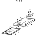
- Fig. 2 is a perspective view of an IC card holder into which an IC card is inserted.
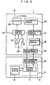
- Fig. 3 is a view illustrating the respective electrical structures of the IC card and the IC card holder.
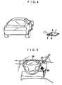
- Fig. 4 is a view of a keyless entry system using the IC card holder.
- Fig. 5 is a view illustrating an instrument panel.
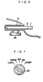
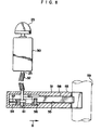
- Fig. 6 is a longitudinal cross-sectional view of a card setting portion.
- Fig. 7 is a front view of an ignition knob.
- Fig. 8 is a view of a connective structure of an ignition switch portion and a steering lock portion.
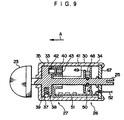
- Fig. 9 is a longitudinal cross-sectional view of the ignition switch portion.
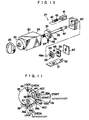
- Fig. 10 is an exploded perspective view of the ignition switch portion.
- Fig. 11 is a view of a detent relationship of a lock plate and a body.
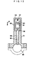
- Fig. 12 is a transverse cross-sectional view of the ignition switch portion.
- Fig. 13 is a view corresponding to Fig. 12 in a rotational state of a cam.
- Fig. 14 is a timing chart illustrating an operational state of the present embodiment.
- Fig. 15 is a view corresponding to Fig. 1 and illustrating a second embodiment of the present invention.
- Fig. 16 is a view corresponding to Fig. 14.
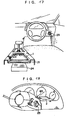
- Fig. 17 is a view corresponding to Fig. 5 and illustrating another embodiment of the present invention.
- Fig. 18 is a view corresponding to Fig. 5 and illustrating another embodiment of the present invention.
- FIG. 1 A description of a first embodiment in which the present invention is applied to an engine starting system for a vehicle will be given with reference to Figs. 1 through 14. Further, in the present embodiment, it is structured such that the engine starting system includes a keyless entry system.
- FIG. 2 shows the appearance of an IC card holder 1 as a media accommodating means, and an IC card 2 as a storing medium which is inserted into the IC card holder 1.
- the IC card 2 is also structured to serve as a driver's license.
- An IC chip 3 including a CPU and EEPROM is embedded in the IC card 2.
- a portrait of the owner of the IC card and characters or the like necessary to be included in the IC card (not shown) are provided on the surface of the IC card 2 through printing and an embossing processing.
- an antenna coil 4 is embedded in the IC card 2 so as to generate an electromagnetic action, and power is supplied to the IC chip 3 due to the electromagnetic action.
- the aforementioned IC card 2 can be inserted into the IC card holder 1.
- the IC card holder 1 holds the IC card 2 in a state in which the IC card 2 is accommodated in the IC card holder 1.
- the IC card holder 1 has a slit 5 at the end surface thereof, into which the IC card 2 is inserted, and is formed in a thin rectangular container shape.
- a lock switch 6, an unlock switch 7 and a trunk opener switch 8 are provided on the upper surface of the IC card holder 1.
- a button-shaped battery 9 is also inserted into the IC card holder 1 via a cartridge 10.
- the IC card 2 is constituted by a control portion 11 mainly consisted of a CPU, a storing portion 12 consisted by EEPROM, and a signal transmitting/receiving portion 13.
- the signal transmitting/receiving portion 13 is consisted of an antenna coil 4.
- a specific ID code for the owner of the IC card 2 is stored in the storing portion 12 in a state in which the ID code is not rewritable.
- optional data can be written to an area other than the area storing the ID code.
- a control portion 14 a signal transmitting/receiving portion 15, an encrypting portion 16, an amplification portion 17, and a transmitting portion 18 are provided in the IC card holder 1.
- the signal transmitting/receiving portion 15 is consisted of a coil opposing the antenna coil 4 in the IC card 2.
- the control portion 14 of the IC card holder 1 is mainly made of a microcomputer. When any one of the lock switch 6, the unlock switch 7, and the trunk opener switch 8 is energized, the control portion 14 outputs a query signal to the signal transmitting/receiving portion 15. The query signal is transmitted to the control portion 11 via the signal transmitting/ receiving portion 13.
- the control portion 14 of the IC card holder 1 controls to transmit a lock operation signal to the amplification portion 17.
- the amplification portion 17 amplifies the signal which is formed by combining the above lock operation signal with an encryption signal having an ID code, and outputs to the transmitting portion 18 the amplified signal as described above. Accordingly, when the lock switch 6 is energized, a lock signal including the encrypted ID code is transmitted from the IC card holder 1 by waves.
- the control portion 14 of the IC card holder 1 outputs signals to the amplification portion 17 an unlock operation signal or a trunk opener operation signal.
- An unlock signal having the encrypted ID code, or an trunk opener signal is output from the IC card holder 1 by waves.
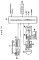
- a system ECU 19 is mounted in a vehicle and serves as an identification-enabling means which receives a signal transmitted from the aforementioned IC card holder 1 (see Fig 1).
- the system ECU 19 decodes an ID code which has been written to the received signal from the IC card holder 1.
- the system ECU 19 is to send instructions to a door trunk control means 20.
- the system ECU 19 instructs the door trunk control means 20 to execute a lock operation.
- the system ECU 19 instructs the door trunk control means 20 to execute an unlock operation.
- the system ECU 19 instructs the door trunk control means 20 to implement a trunk opening operation.
- the door trunk control means 20 When the door trunk control means 20 has received a lock instruction or an unlock instruction from the system ECU 19, the door trunk control means 20 operates to lock or unlock a door lock mechanism (not shown), while, when the door trunk control means 20 has received a trunk opening instruction, the door trunk control means 20 operates to unlock a trunk lid mechanism (not shown).
- Fig. 5 shows a front of a driver's seat of the vehicle.
- a card setting portion 21 which is formed in a throttle shape is provided at a dashboard which is continuous with an instrument panel at the side of the driver's seat.
- the IC card holder 1 into which the IC card 2 has been inserted is set into the card setting portion 21.
- an ignition knob 23 serving as an operation means is provided at a portion of the instrument panel at the side of the steering wheel 22.
- the ignition knob 23 is structured such that the rotational operation thereof is enabled only in a state in which the IC card holder 1 including an ordinary IC card 2 has been set into the card setting portion 21.
- Fig. 6 shows a cross section of the card setting portion 21.
- communication means 24 having a coil therein is disposed at a lower position of the card setting portion 21.
- the IC card 2 which has been inserted into the IC card holder 1 is disposed so as to oppose the coil of the communication means 24 in a state in which the IC card holder 1 has been set into the card setting portion 21.
- a LOCK position, CHECK position, ACC position, ON position, and START position are provided at the ignition knob 23.
- the LOCK position and CHECK position are set to a run-inhibiting position, respectively.
- the ACC position, ON position and START position are set to a run-enabling position, respectively. It should be noted that, when the ignition knob 23 has been set to the LOCK position, only the rotational operation thereof to the CHECK position is permitted.
- Fig. 1 shows a schematic overall structure of the engine starting system and the keyless entry system which have been described above.
- the aforementioned ignition knob 23 is connected to a switch 26 serving as an operating position detecting portion via a shaft 25.
- a knob rotation-inhibiting means 27 and a steering lock cancellation means 28 serving as an operation-inhibiting means are provided at the shaft 25.
- the knob rotation inhibiting means 27 inhibits the rotation of the shaft 25 or the ignition knob 23, while in a state in which a permission code serving as the operation-enabling signal has been input from the system ECU 19, the knob rotation inhibiting means 27 cancels the inhibiting state of the rotation of the shaft 25. More specifically, when the ignition knob 23 has been set to the LOCK position, further rotational operation to any one of the ACC, ON, and START positions due to the ignition knob 23 is inhibited, while in a state in which a permission code has been output from the system ECU 19, the further rotational operation to any one of the ACC, ON, and START positions due to the ignition knob 23 is enabled.
- the steering lock cancellation means 28 cancels the inhibiting state of the rotation of the steering wheel 22 due to a steering lock means 29.
- Fig. 8 shows an ignition switch portion 30 having a switch 26 and a knob rotation inhibiting means 27, and a steering lock portion 31 having a steering lock cancellation means 28 and a steering lock means 29.
- a flexible shaft 32 serving as a flexible connecting means is fixed to the shaft 25 of the ignition switch portion 30. Via the flexible shaft 32, the rotational force due to the ignition knob 23 which is mounted to the ignition switch portion 30 is transmitted to the steering lock portion 31.
- the flexible shaft 32 is a connecting member having a flexibility which enables the rotational force from the shaft 25 to be transmitted to a shaft 60 in spite of its orientation.
- the ignition switch portion 30 is assembled in a body 34 as a housing which has a substantially rectangular cylindrical shape whose end portion is open, and has a cylinder-shaped portion 33 at the tip thereof.
- the open end portion of the body 34 is closed by a cap 67.
- the shaft 25 passes through the tip of the body 34 and the cap 67 so as to be rotatably supported.
- the ignition knob 23 is installed at the tip of the shaft 25 projecting from the front of the ignition switch portion 30.
- a disc-shaped lock plate 35 is provided to be integral with the shaft 25, and is disposed within the cylinder-shaped portion 33 of the ignition switch portion 30.
- An engaging groove portion 36 (only shown in Fig. 10) is formed at the outer peripheral surface portion of the lock plate 35 so as to make a predetermined angle with respect to a radius of the shaft 25 which has a common center with the lock plate 35.
- An engaging pawl portion (not shown), which is provided at the inner surface portion of the cylinder-shaped portion 33, engages with the engaging groove portion 36, and allows the ignition knob 23 to only rotate from the LOCK position to the START position.
- an urging force is applied to the ignition knob 23 by an unillustrated urging means so that the ignition knob 23 is allowed to return to the ON position constantly between the ON position and the START position.
- a detent ball 37 is provided at the outer peripheral surface portion of the lock plate 35 so as to project therefrom due to an urging force generated by a compression coil spring 38.
- the detent ball 37 engages with a zigzag-shaped detent portion 39 formed at the inner surface portion of the cylinder-shaped portion 33 so that detent is applied to the ignition knob 23 at each of the operational positions of the CHECK position, ACC position, and ON position.
- a stopper 40 is fitted into the body 34, which allows the lock stopper 35 to be positioned.
- An electromagnetic solenoid 41 is fixed to the stopper 40.
- a lock pin 42 serving as a plunger projects in a direction of the arrow indicated by A which is shown in Fig. 9.
- the lock pin 42 engages with the lock plate 35, through which engagement the rotation of the lock plate 35 can be controlled. More specifically, as shown in Fig. 11, a first groove portion 44 and a second groove portion 45 are provided at the back surface portion of the lock plate 35 concentric to the lock plate 35 so as to form a predetermined angle therebetween.
- the lock pin 42 is inserted into the first groove portion 44 or the second groove portion 45.
- the first groove portion 44 corresponds to the angle between the LOCK position and the CHECK position. Accordingly, as shown in Fig.
- the knob rotation inhibiting means 27 is constituted by the aforementioned lock plate 35 and lock pin 42.
- a LOCK position detent valley 39a a LOCK position detent valley 39a, a CHECK position detent slope 39b, an ACC position detent valley 39c, an ON position detent valley 39d, and a START position detent slope 39e are formed at the detent portion 39.
- the detent ball 37 is positioned at one of the LOCK position detent valley 39a, ACC position detent valley 39c, and ON position.
- detent valley 39d the detent ball 37 is fitted into one of the aforementioned detent valleys 39a, 39c, and 39d, and detent is applied to the ignition knob 23 at each of the detent positions.
- the ignition knob 23 is formed into a momentary configuration so as to return from the CHECK position to the LOCK position, or the ignition knob 23 is formed into a momentary configuration so as to return from the ON position to the START position.
- an engaging projection 47 is formed at the shaft 25 and a contact holder 49 having a contact 48 is fixed thereto.
- a through-hole 49a having a plurality of slits is formed at the contact holder 49, and the engaging projection 47 engages with the through-hole 49a so that the contact holder 49 and the shaft 25 are integrated with each other.
- an insulator 50 is secured to the body 34 so as to face the contact holder 49.
- a fixing contact is provided on the surface of the insulator 50.
- a switch 26 comprises the fixing contact and the contact 48. In a state in which the ignition knob 23 has been set to each operational position, the switch 26 corresponding to the selected operational position is turned on.
- a printed wiring board 51 is disposed in the body 34 and a control circuit is installed on the printed wiring board 51.
- the control circuit operates the electromagnetic solenoid 41. Meanwhile, when the permission code is no longer input from the ECU, the control circuit terminates the operation for the electromagnetic solenoid 41. Further, the control circuit inputs an ON signal from the switch 26, and outputs a code signal indicating the position of the ignition knob 23 via the lead 52 on the basis of the input ON signal. More specifically, when the switch 26 corresponding to LOCK position is turned on, the control circuit outputs "001" as a code signal. When the switch 26 corresponding to the CHECK position is turned on, the control circuit outputs "010" as a code signal.
- the control circuit When the switch 26 corresponding to the ACC position is turned on, the control circuit outputs "011" as a code signal. When the switch 26 corresponding to the ON position is turned on, the control circuit outputs "100” as a code signal. When the switch 26 corresponding to the START position is turned on, the control circuit outputs "101" as a code signal.
- Fig. 12 shows the steering lock portion 31 which is connected to the ignition knob 23 via the ignition switch portion 30 and the flexible shaft 32 which have been described above.
- a sliding space portion 54 having a predetermined configuration and a through-hole 55 communicating with the sliding space portion 54 are disposed along the longitudinal direction of an elongated body 53.
- a lock stopper 56 having a rectangular framed configuration is disposed at the sliding space portion 54 so as to be slidable therewith.
- a compression coil spring 57 is provided between the lock stopper 56 and the inner peripheral wall of the slide space portion 54. Due to the urging force from the compression coil spring 57, the lock stopper 56 is pressed in the direction of the arrow indicated by B.
- an elongated lock bar 58 is inserted into the through-hole 55.
- the tip end portion of the lock bar 58 projects from the body 53 in a state in which the proximal end portion of the lock bar 58 engages with the lock stopper 56.
- the lock bar 58 projecting from the body 53 engages with a concave portion (not shown) formed at a steering shaft 59. In this engaging state, the rotation of the steering shaft 59 is inhibited.
- the steering lock cancellation means 29 is constituted by the lock stopper 56, the compression coil spring 57, and the lock bar 58.
- a shaft 60 is supported by the sliding space portion 54 of the body 34 so as to be rotatable.
- a cam 61 is mounted to the shaft 61, and is disposed in the lock stopper 56 so that the inner peripheral surface of the lock stopper 56 abuts the outer peripheral surface of the cam 61 due to the urging force from the compression coil spring 57.
- the flexible shaft 32 which is connected to the shaft 25 of the ignition switch portion 30, is connected to the shaft 60 of the steering lock portion 31.
- the rotation of the ignition knob 23 is transmitted to the cam 61 via the flexible shaft 32.
- the cam 61 is formed into a configuration such that, when the ignition knob 23 has been set between the ACC position and the START position, the lock stopper 56 is caused to move in a direction opposite to that of the arrow B so as to resist the urging force from the compression coil spring 57. Accordingly, the entire portion of the lock bar 58 is incorporated into the body 53 due to the movement of the lock stopper 56 by the cam 61 (see Fig. 13).
- the system ECU 19 comprises the keyless entry system and the engine starting system.
- the system ECU 19 as the keyless entry system outputs an instruction to the door trunk control means 20 in response to the received signal from the IC card holder 1.
- the system ECU 19 as the engine starting system reads the IC code stored in the IC card 2 via the communication means 24, outputs a permission code to an engine ECU 62 in response to the input code from the switch 26 of the ignition switch portion 30 at the time when the IC code read corresponds to the preset register code, and outputs one of the ACC signal, ON signal, and START signal as needed.
- the engine ECU 62 receives the input of an ON signal or a START signal only in a state in which a permission code has been input from the system ECU 19, and starts a vehicle engine in response to the input of the START signal.
- the driver When a driver gets in a vehicle, the driver operates the unlock switch 7 in a state in which the IC card 2 which doubles as the driver's license is inserted into the IC card holder 1.
- The, the unlock signal storing an ID code therein is transmitted from the IC card holder 1 by waves.
- the system ECU 19 which has been installed at the vehicle, determines whether or not the ID code from the received unlock signal and the preset register code correspond to each other. When they correspond to each other, the system ECU 19 instructs the door trunk control means to unlock the door lock mechanism in response to the unlock signal.
- the door trunk control means 20 unlocks the door lock mechanism, and a passenger can open a vehicle door and get in the vehicle.
- the driver When a driver starts the vehicle engine, he or she sets the IC card holder 1 in the card setting portion 21 provided at a dashboard box. Thereafter, the driver rotationally operates the ignition knob 23 in a clockwise direction from the LOCK position. At this time, since the lock pin 42 is inserted into the first groove portion 44 formed at the back surface portion of the lock plate 35, in this inserted state, the ignition knob 23 is only enabled to rotate from the LOCK position to the CHECK position. Therefore, even when the ignition knob 23 is rotationally operated in a clockwise direction, the ignition knob 23 can only rotate to the CHECK position.
- a code indicating that the ignition knob 23 has been set to the CHECK position is output to the system ECU 19 from the control circuit on the printed wiring board 51 of the ignition switch portion 30.
- the system ECU 19 is thereby set in an activating state (see Fig. 14(a)) so as to read the ID code stored in the storing portion 12 of the IC card 2 by communicating with the IC card 2 in a state of supplying power to the IC card 2 via the communication means 24, and determines whether or not the read ID code corresponds to the preset register code (see Fig 14(b)).
- the system ECU 19 When the ID code read corresponds to the preset register code, the system ECU 19 outputs a permission code to the engine ECU 62. Therefore, the engine ECU 62 is transferred to a state in which the vehicle engine is enabled being started (see Fig 14(c)).
- the control circuit which has received the permission code, causes the electromagnetic solenoid 41 to operate.
- the lock pin 42 is attracted by the electromagnetic solenoid 41, and the lock pin 42, which has been inserted into the first groove portion 44 of the lock plate 35, escapes from the first groove portion 44 so that the rotation of the lock plate 35 is enabled.
- the rotational operation of the ignition knob 23 from the CHECK position to the ACC position and its further positions is permitted (see Fig 14(d)).
- the length of time from the time during which the ignition knob 23 is set to the CHECK position to the time during which the rotational operation of the ignition knob 23 is permitted due to the operation of the electromagnetic solenoid 41 is extremely short. Accordingly, when an ordinary IC card is used, the ignition knob 23 can easily be set to the ACC position and its further positions by way of the LOCK position and the CHECK position.
- a code indicating that the ignition knob 23 has been set to the START position is output from the switch 26 of the ignition switch portion 30 (see Figs. 14(g), (h)). Accordingly, the engine ECU 62 inputs the ON signal in a state in which the engine ECU 62 has received a permission code, and thereafter, inputs a START signal so as to start the engine.
- the rotational operation due to the ignition knob 23 from the ON position to the START position is structured as a momentary method, when the ignition knob 23 has been rotationally operated to the START position, and thereafter, the rotational operation thereof has been canceled, the ignition knob 23 automatically returns to the ON position. As a result, the ignition knob 23 can operate in the same manner as a conventional ignition key.
- a vehicle speed signal is input to the system ECU 19 from a vehicle speed sensor (not shown) (see Fig. 14 (i)). Accordingly, the system ECU 19 stops outputting of a permission code with respect to the ignition switch portion 30. Then, since the control circuit of the ignition switch portion 30 stops the operation for the electromagnetic solenoid 41 in cooperation with the above stopping operation, the lock pin 42 projects toward the lock plate 35 due to the urging force from the compression coil spring 43. At this time, since the ignition knob 23 has been set to the ON position, the projected lock pin 42 is caused to be inserted into the second groove portion 45 which is provided at the back surface portion of the lock plate 35.
- the ignition knob 23 can rotate between the ACC position and the START position, and the rotational operations to the CHECK position and the LOCK position are thereby inhibited (see Fig. 14(d)).
- the vehicle speed signal which has been output to the system ECU 19 is interrupted so that the system ECU 19 again outputs a permission code to the ignition switch portion 30. Accordingly, the electromagnetic solenoid 41 is operated, and the lock pin 42, which has been inserted into the second groove portion 45 of the ignition knob 23, escapes from the second groove portion 45 so that the rotation of the ignition knob 23 is permitted (see Fig. 14(d)).
- the ignition knob 23 is rotationally operated to the LOCK position. Then, the system ECU determines that the activation of the system has been finished, and thereby terminates outputs from various types of signals such as the output of a permission code to the engine ECU 62, the output of a permission code to the ignition switch portion 30, outputs from the ACC and ON and START signals, and the like. Therefore, in accordance with the termination of the system due to the system ECU 19, the lock pin 42 is inserted again into the first groove portion 44 of the ignition knob 23 so that the rotation of the ignition knob 23 is controlled once again.
- the IC card 2 which has been inserted into the IC card holder 1 is used to assemble the engine starting system, as far as the IC card is an ordinary one, the rotational operation with respect to the ignition knob 23 is permitted, while the rotational operation with respect to the steering wheel 22 is inhibited or enabled on the basis of the aforementioned rotational operation. Accordingly, using the IC card 2 provides the same function as an ordinary or conventional ignition key.
- the vehicle starting system When the ID code which has been stored in the IC card 2 corresponds to a predetermined identification code, the system is activated and, only with the system in the activated state, the starting of the engine is enabled in accordance with the rotational position of the ignition knob 23. Therefore, by the vehicle starting system according to the present first embodiment, a higher safety can be provided as compared to a conventional ignition key.
- the IC card 2 is used so as to integrally assemble a keyless entry system in the engine starting system of the present invention as well, the added value of the system can be increased and the commercial value thereof can be improved accordingly.
- the knob rotation inhibiting means 27, the switch 26, and the like are housed in the body 34 in a closed state. Signals output from the switch 26 are encoded, and the safety of the ignition knob 23 is thereby improved.
- the relationship between the orientation of the ignition switch portion 30 and the steering lock 31 used to have a specified constraint since the shaft 25 and the shaft 60 are connected to each other by a flexible shaft 32 having flexibility, an arbitrary relationship between the orientation of the ignition switch portion 30 and the steering rod portion 31 can be secured. Therefore, the degree of freedom in designing a vehicle increases, and errors caused by operational irregularities at the time of production and assembly are reduced.
- Figs. 15 and 16 a second embodiment of the present invention is shown. Portions identical to those shown in the second embodiment are denoted by the same reference numbers and a description thereof will be omitted.
- the above-described second embodiment is structured such that the removal of the IC card 2 is inhibited in a state that the IC card 2 has been inserted into the card setting portion 63.
- a third embodiment of the present invention is characterized in that the shutter 65 for inhibiting the removal of the IC card 2 is detached so as to optionally remove the IC card 2 from the card setting portion 63. Accordingly, when the ignition knob 23 has been set to the LOCK position in a state in which the IC card 2 has been removed from the card setting portion 63, the system ECU 19 immediately inhibits permission to start the engine ECU 62, permission to rotate the ignition knob 23, and permission to rotate the steering shaft 59.
- the card setting portion 21 into which the IC card holder 1 is inserted, or the card setting portion 63 into which the IC card holder 2 is inserted 21 may be installed at a center console as shown in Fig. 17, or may be installed at a steering column cover as shown in Fig. 18.
- the ignition knob 23 may effect a sliding operation instead of a rotational operation.
- a memory card may be used instead of an IC card.
- An IC card having a contact may be used so as to effect a communication in an electrically conductive state via the contact.
- a vehicle starting control device can effect inhibition and enabling of the rotation of a steering shaft as far as a storing medium is used as an ignition key. As a result, it is effective in the automobile industry to assemble a keyless entry system in the vehicle starting control device and to improve the safety of the system.
Claims (10)
- Dispositif de commande de démarrage pour véhicule, comprenant :caractérisé en ce que les moyens (23) de commande comprennent en outre une vérification de position qui juge en vrai ou faux pour ledit support (2) de stockage entre ladite position d'interdiction de démarrage et ladite position d'autorisation de démarrage ;un support (2) de stockage qui stocke un code spécifique d'identification ;des moyens (1) de réception de support qui sont prévus dans un véhicule et peuvent recevoir en eux ledit support (2) de stockage ;des moyens (24) de communication qui peuvent communiquer avec ledit support (2) de stockage dans un état où ledit support (2) de stockage a été reçu dans lesdits moyens (1) de réception de support ;des moyens (23) de commande qui peuvent fonctionner entre une position d'interdiction de démarrage qui empêche le fonctionnement du véhicule et une position d'autorisation de démarrage comprenant une position de démarrage du moteur,
et caractérisé pardes moyens (29) de blocage de direction qui empêchent la rotation d'un arbre de direction dans un état où lesdits moyens (23) de commande ont été mis sur la position d'interdiction de démarrage ;des moyens (28) d'annulation de blocage de direction qui annulent un état d'inhibition de la rotation de l'arbre de direction dû auxdits moyens (29) de blocage de direction dans un état où lesdits moyens (23) de commande ont été mis sur ladite position d'autorisation de démarrage ;des moyens (27, 28) d'inhibition de fonctionnement qui empêchent lesdits moyens (23) de commande de changer de position entre ladite position d'interdiction de démarrage et ladite position d'autorisation de démarrage ; etdes moyens (19) d'activation d'identification qui, quand lesdits moyens (23) de commande ont été mis sur la position de vérification, lisent un code d'identification stocké dans ledit support (2) de stockage par l'intermédiaire desdits moyens (24) de communication, vérifient si le code d'identification lu et un code de registre qui a été enregistré préalablement correspondent ou non l'un à l'autre, et, quand ledit code d'identification lu et le code de registre correspondent l'un à l'autre, autorisent d'effectuer une opération de changement de position entre ladite position d'interdiction de démarrage et ladite position d'autorisation de démarrage. - Dispositif de commande de démarrage pour véhicule selon la revendication 1, dans lequel, quand lesdits moyens (23) de commande ont été mis sur la position d'interdiction de démarrage dans un état où une opération de changement de position a été autorisée, lesdits moyens d'activation d'identification annulent l'autorisation de l'opération de changement de position.
- Dispositif de commande de démarrage pour véhicule selon la revendication 1, comprenant en outre des moyens (26) de détection de position de fonctionnement pour détecter dans laquelle de la position d'interdiction de démarrage et de la position d'autorisation de démarrage lesdits moyens (23) de commande ont été mis.
- Dispositif de commande de démarrage pour véhicule selon la revendication 1, dans lequel lesdits moyens (24) de communication communiquent avec ledit support (2) de stockage par l'intermédiaire d'un coupleur électromagnétique (41).
- Dispositif de commande de démarrage pour véhicule selon la revendication 1, dans lequel lesdits moyens (19) d'activation d'identification cryptent un signal d'autorisation de fonctionnement indiquant la permission de fonctionnement donnée par lesdits moyens (23) de commande, et émettent ce signal.
- Dispositif de commande de démarrage pour véhicule selon la revendication 2, dans lequel lesdits moyens (19) d'activation d'identification empêchent l'autorisation de ladite opération de changement de position d'être annulée pendant que le véhicule est dans un état de fonctionnement.
- Dispositif de commande de démarrage pour véhicule selon la revendication 3, dans lequel lesdits moyens (26) de détection de position de fonctionnement cryptent un signal de position de fonctionnement indiquant une position de fonctionnement donnée par lesdits moyens (23) de commande, et émettent ce signal.
- Dispositif de commande de démarrage pour véhicule selon la revendication 3, dans lequel lesdits moyens d'activation d'identification, lesdits moyens (27, 28) d'inhibition de fonctionnement et lesdits moyens (26) de détection de position de fonctionnement sont installés dans un boítier fermé formant coffret.
- Dispositif de commande de démarrage pour véhicule selon la revendication 1, dans lequel lesdits moyens (23) de commande et/ou lesdits moyens (27, 28) d'inhibition de fonctionnement et lesdits moyens (29) de blocage de direction et/ou lesdits moyens (28) d'annulation de blocage de direction sont reliés les uns aux autres par des moyens flexibles (32) de liaison ayant une souplesse de manière à pouvoir être reliés les uns aux autres quelle que soit leur orientation.
- Dispositif de commande de démarrage pour véhicule selon la revendication 9, dans lequel, quand lesdits moyens (23) de commande ont été manoeuvrés, la manoeuvre est transmise sous la forme d'une force de rotation auxdits moyens (29) de blocage de direction et/ou auxdits moyens (28) d'annulation de blocage de direction par l'intermédiaire desdits moyens flexibles (32) de liaison.
Applications Claiming Priority (4)
| Application Number | Priority Date | Filing Date | Title |
|---|---|---|---|
| JP29632994 | 1994-11-30 | ||
| JP296329/94 | 1994-11-30 | ||
| JP29632994 | 1994-11-30 | ||
| PCT/JP1995/002417 WO1996016844A1 (fr) | 1994-11-30 | 1995-11-28 | Appareil de controle du demarrage d'un vehicule |
Publications (3)
| Publication Number | Publication Date |
|---|---|
| EP0794095A1 EP0794095A1 (fr) | 1997-09-10 |
| EP0794095A4 EP0794095A4 (fr) | 2002-06-19 |
| EP0794095B1 true EP0794095B1 (fr) | 2004-03-03 |
Family
ID=17832134
Family Applications (1)
| Application Number | Title | Priority Date | Filing Date |
|---|---|---|---|
| EP95937198A Expired - Lifetime EP0794095B1 (fr) | 1994-11-30 | 1995-11-28 | Appareil de controle du demarrage d'un vehicule |
Country Status (4)
| Country | Link |
|---|---|
| US (1) | US5801614A (fr) |
| EP (1) | EP0794095B1 (fr) |
| DE (1) | DE69532643T2 (fr) |
| WO (1) | WO1996016844A1 (fr) |
Families Citing this family (59)
| Publication number | Priority date | Publication date | Assignee | Title |
|---|---|---|---|---|
| FR2753156B1 (fr) * | 1996-09-11 | 1998-10-16 | Valeo Securite Habitacle | Antivol pour vehicule automobile |
| JPH10171942A (ja) * | 1996-12-11 | 1998-06-26 | Tokai Rika Co Ltd | データキャリアシステム |
| JPH10315914A (ja) * | 1997-05-19 | 1998-12-02 | Tokai Rika Co Ltd | 車両用始動装置 |
| AU7628398A (en) | 1997-09-12 | 1999-03-25 | Robert Bosch Gmbh | An ignition lock system |
| DE19747732B4 (de) * | 1997-10-29 | 2004-01-29 | Robert Bosch Gmbh | Fahrberechtigungssystem, insbesondere für Kraftfahrzeuge |
| US6388558B1 (en) * | 1997-12-03 | 2002-05-14 | Adc Technology Inc. | Key system |
| DE19813068A1 (de) * | 1998-03-25 | 1999-10-07 | Bosch Gmbh Robert | Start-/Fahrberechtigungssystem für ein Fahrzeug |
| DE19839349C1 (de) * | 1998-08-28 | 2000-04-13 | Daimler Chrysler Ag | Wegfahrsperreinrichtung für ein Kraftfahrzeug |
| DE19847391A1 (de) * | 1998-10-14 | 2000-07-20 | Bosch Gmbh Robert | Steuervorrichtung für Zündung und Lenkungsverriegelung eines Kraftfahrzeugs |
| SE9804469L (sv) | 1998-12-21 | 2000-06-22 | Volvo Ab | Anordning vid ett motorfordon |
| DE19860350C5 (de) * | 1998-12-24 | 2011-01-13 | Leopold Kostal Gmbh & Co. Kg | Schlüssellose Motorstartberechtigungskontrolleinrichung |
| DE19907374B4 (de) * | 1999-02-20 | 2016-08-18 | Volkswagen Ag | Elektronisches Zündstartschloßsystem für ein Kraftfahrzeug |
| DE19908704B4 (de) * | 1999-02-26 | 2008-06-19 | Leopold Kostal Gmbh & Co. Kg | Manuell betätigbarer Zündanlaßschalter |
| US20030169150A1 (en) * | 1999-03-23 | 2003-09-11 | Brendzel Henry Tzvi | Arrangement for prevention of motor vehicle thefts |
| US6531955B1 (en) * | 1999-03-23 | 2003-03-11 | Henry Tzvi Brendzel | Arrangement for prevention of motor vehicle thefts |
| FR2791936B1 (fr) | 1999-04-09 | 2001-06-01 | Valeo Securite Habitacle | Antivol de vehicule automobile |
| FR2791937B1 (fr) * | 1999-04-09 | 2001-06-01 | Valeo Securite Habitacle | Antivol perfectionne de vehicule automobile |
| DE19916966C5 (de) * | 1999-04-15 | 2006-09-21 | Daimlerchrysler Ag | Elektronische Zündstartschalter- und Lenkradverriegelungsvorrichtung |
| FR2792753B1 (fr) † | 1999-04-20 | 2001-11-02 | Valeo Securite Habitacle | Systeme d'autorisation de demarrage pour un vehicule automobile |
| US6396388B1 (en) * | 1999-05-26 | 2002-05-28 | Dawei Dong | Remote starting device for cars |
| US7064651B2 (en) | 2000-04-12 | 2006-06-20 | Goetz Joseph R | Automatic vehicle theft prevention system |
| JP4481438B2 (ja) * | 2000-05-31 | 2010-06-16 | 株式会社東海理化電機製作所 | シフト装置 |
| JP4481437B2 (ja) | 2000-05-31 | 2010-06-16 | 株式会社東海理化電機製作所 | シフト装置 |
| DE10055361C2 (de) * | 2000-11-08 | 2003-02-27 | Huf Huelsbeck & Fuerst Gmbh | Vorrichtung mit einer Lenkungsverriegelung sowie mit einem Zündanlassschalter, die bei Anwesenheit eines Identifikationsgebers von einer Handhabe steuerbar sind |
| US6708086B2 (en) * | 2000-12-11 | 2004-03-16 | Sue M. Richard | Vehicle computer |
| JP4226227B2 (ja) * | 2001-03-07 | 2009-02-18 | 三菱電機株式会社 | カードモジュール用シャッタ機構 |
| DE10123700A1 (de) * | 2001-05-15 | 2003-01-02 | Kostal Leopold Gmbh & Co Kg | Schlüssellose Motorstartberechtigungskontrolleinrichtung für Kraftfahrzeuge |
| US6616054B1 (en) | 2001-07-02 | 2003-09-09 | Bellsouth Intellectual Property Corporation | External power supply system, apparatus and method for smart card |
| US6604685B1 (en) * | 2001-07-02 | 2003-08-12 | Bellsouth Intellectual Property Corporation | Optical smart card system, apparatus and method |
| US6705531B1 (en) | 2001-07-02 | 2004-03-16 | Bellsouth Intellectual Property Corp. | Smart card system, apparatus and method with alternate placement of contact module |
| US6572015B1 (en) * | 2001-07-02 | 2003-06-03 | Bellsouth Intellectual Property Corporation | Smart card authorization system, apparatus and method |
| DE10233061A1 (de) * | 2001-07-25 | 2003-02-13 | Marquardt Gmbh | Zündschloßsystem für ein Kraftfahrzeug |
| JP3847140B2 (ja) | 2001-10-30 | 2006-11-15 | 株式会社モリック | 乗り物における盗難防止装置 |
| JP3546041B2 (ja) * | 2002-02-15 | 2004-07-21 | 日産自動車株式会社 | 車載機器通信制御装置 |
| JP2003269019A (ja) * | 2002-03-14 | 2003-09-25 | Calsonic Kansei Corp | 車両用無線装置 |
| JP3571705B2 (ja) * | 2002-04-01 | 2004-09-29 | 株式会社東海理化電機製作所 | エンジン始動制御装置 |
| JP3715938B2 (ja) * | 2002-04-01 | 2005-11-16 | 株式会社東海理化電機製作所 | エンジン始動・停止制御システム |
| EP1363249A1 (fr) * | 2002-05-15 | 2003-11-19 | Teleco Automation S.R.L. | Clé de véhicule comprenant une télécommande à utilisateurs multiples |
| DE10238710A1 (de) * | 2002-08-23 | 2004-03-04 | Metabowerke Gmbh | Elektrohandwerkzeuggerät |
| JP4276421B2 (ja) * | 2002-11-08 | 2009-06-10 | 株式会社東海理化電機製作所 | スロット機構 |
| DE10253936A1 (de) * | 2002-11-19 | 2004-06-03 | Bayerische Motoren Werke Ag | Verfahren zur Sicherung eines KFZ gegen Wegrollen nach Abstellen des Motors sowie Sicherheitseinrichtung |
| JP4593465B2 (ja) * | 2003-02-14 | 2010-12-08 | 本田技研工業株式会社 | Icタグ搭載のスクータ型自動二輪車 |
| JP3997948B2 (ja) * | 2003-05-22 | 2007-10-24 | トヨタ自動車株式会社 | 車両識別コード記憶装置 |
| JP4195842B2 (ja) * | 2003-07-28 | 2008-12-17 | 株式会社東海理化電機製作所 | エンジン始動・停止制御システム |
| DE102004019919B3 (de) * | 2004-04-21 | 2006-02-02 | Huf Hülsbeck & Fürst Gmbh & Co. Kg | Vorrichtung zum Starten eines Fahrzeugmotors mittels eines elektronischen Schlüssels und ein dazu zu verwendener Schlüssel |
| EP1698531A1 (fr) * | 2005-03-03 | 2006-09-06 | Huf Hülsbeck & Fürst GmbH & Co. KG | Blocage de volant de direction sur une automobile |
| DE102005038437A1 (de) * | 2005-08-12 | 2007-02-15 | Huf Hülsbeck & Fürst GmbH & Co KG | Zündvorrichtung für einen Motor, insbesondere in einem Kraftfahrzeug |
| US7990254B2 (en) * | 2007-07-17 | 2011-08-02 | GM Global Technology Operations LLC | Method and system for controlling an ignition switch and an operational state of a vehicle |
| US20110208413A1 (en) * | 2007-07-30 | 2011-08-25 | Jae Woo Yang | Apparatus and method for starting automobile using start-button |
| JP2009116650A (ja) * | 2007-11-07 | 2009-05-28 | Nec Access Technica Ltd | 車載器制御システム、車載器制御方法、および車載器制御プログラム |
| US7589434B1 (en) | 2008-02-22 | 2009-09-15 | Brian Bronson | Auto anti-theft device |
| JP5021522B2 (ja) * | 2008-02-26 | 2012-09-12 | 株式会社東海理化電機製作所 | カード型電子キー |
| DE102009027051A1 (de) * | 2009-06-19 | 2011-01-05 | Huf Hülsbeck & Fürst Gmbh & Co. Kg | Schlüssel für ein Schlosssystem eines Kraftfahrzeugs |
| JP5394981B2 (ja) * | 2010-05-13 | 2014-01-22 | 株式会社東海理化電機製作所 | イグニッションスイッチの操作規制装置 |
| US8930087B2 (en) | 2011-08-09 | 2015-01-06 | GM Global Technology Operations LLC | Systems and methods for interference reduction during keyless ignition authentication |
| WO2015053537A1 (fr) * | 2013-10-07 | 2015-04-16 | 주식회사 대동 | Carte-clé intelligente de type mince pour véhicule et procédé de commande associé |
| CN104590205B (zh) * | 2013-10-31 | 2017-02-08 | 北汽福田汽车股份有限公司 | 用于控制车辆旋钮式被动启动系统点火锁的电磁阀的方法 |
| US11440301B2 (en) | 2020-03-27 | 2022-09-13 | Faurecia Interior Systems, Inc. | Light permeable vehicle interior panel |
| CN112959926B (zh) * | 2021-03-05 | 2022-11-29 | 广西双英集团股份有限公司 | 一种面向动态多任务汽车座舱平台的时分控制方法 |
Family Cites Families (25)
| Publication number | Priority date | Publication date | Assignee | Title |
|---|---|---|---|---|
| US3755777A (en) * | 1968-03-07 | 1973-08-28 | J Lee | Ignition code override device |
| US4327353A (en) * | 1978-03-06 | 1982-04-27 | George W. Beard | Security system |
| JPS6018026U (ja) * | 1983-07-15 | 1985-02-07 | 金内 靖雄 | 自動車用免許証の強制携帯装置 |
| JPS60148757A (ja) * | 1984-01-13 | 1985-08-06 | Kokusan Kinzoku Kogyo Co Ltd | ステアリングロック装置 |
| JPS60183246A (ja) * | 1984-03-01 | 1985-09-18 | Nissan Motor Co Ltd | 車両用施解錠制御装置 |
| JPS61196080A (ja) * | 1985-02-21 | 1986-08-30 | 日産自動車株式会社 | 無線式利用者識別装置 |
| JPS6237479A (ja) * | 1985-08-12 | 1987-02-18 | 日産自動車株式会社 | 無線式施解錠制御装置 |
| US4777377A (en) * | 1985-09-06 | 1988-10-11 | Jeter Herman C | Vehicle anti-theft system |
| JPS6278379A (ja) * | 1985-09-30 | 1987-04-10 | 日産自動車株式会社 | 車両用施解錠制御装置 |
| GB2194580B (en) * | 1986-04-10 | 1990-08-01 | Kokusan Kinzoku Kogyo Kk | Vehicle lock system |
| JPS6452549A (en) * | 1987-08-20 | 1989-02-28 | Niles Parts Co Ltd | Automobile control device by card system |
| JP2642360B2 (ja) * | 1987-09-10 | 1997-08-20 | 日産自動車株式会社 | ステアリングロック装置 |
| JPH01128449A (ja) * | 1987-11-12 | 1989-05-22 | Ricoh Co Ltd | 平担化された層間絶縁膜の形成方法 |
| JPH0714098Y2 (ja) * | 1988-02-26 | 1995-04-05 | オムロン株式会社 | 車載用リモートコントロール装置 |
| JPH0361146A (ja) * | 1989-07-31 | 1991-03-15 | Nissan Motor Co Ltd | ステアリングロック装置 |
| JP2566012B2 (ja) * | 1989-08-15 | 1996-12-25 | 日産自動車株式会社 | ステアリングロック装置 |
| JP2757535B2 (ja) * | 1990-05-31 | 1998-05-25 | 日産自動車株式会社 | 車両用制御装置 |
| EP0426114B1 (fr) * | 1989-11-02 | 1997-02-26 | Nissan Motor Co., Ltd. | Système de serrure sans clé pour véhicule |
| JPH03148352A (ja) * | 1989-11-02 | 1991-06-25 | Nissan Motor Co Ltd | 車両用キーレス制御装置 |
| JPH03148353A (ja) * | 1989-11-02 | 1991-06-25 | Nissan Motor Co Ltd | 車両用キーレス制御装置 |
| US5434395A (en) * | 1990-03-05 | 1995-07-18 | Jean-Rene Storck | Method and device for effecting a transaction between a first and at least one second data carrier and carrier used for this purpose |
| US5412378A (en) * | 1990-06-13 | 1995-05-02 | Clemens; Jon K. | Antitheft protection of devices |
| JP2998907B2 (ja) * | 1991-02-28 | 2000-01-17 | 株式会社アルファ | ステアリングロック装置 |
| US5433096A (en) * | 1993-08-26 | 1995-07-18 | Strattec Security Corporation | Key assembly for vehicle ignition locks |
| DE69623527T2 (de) * | 1995-04-11 | 2003-05-22 | Tokai Rika Co | Startsteuerung für Fahrzeuge |
-
1995
- 1995-11-28 EP EP95937198A patent/EP0794095B1/fr not_active Expired - Lifetime
- 1995-11-28 US US08/849,088 patent/US5801614A/en not_active Expired - Lifetime
- 1995-11-28 WO PCT/JP1995/002417 patent/WO1996016844A1/fr active IP Right Grant
- 1995-11-28 DE DE69532643T patent/DE69532643T2/de not_active Expired - Lifetime
Also Published As
| Publication number | Publication date |
|---|---|
| EP0794095A4 (fr) | 2002-06-19 |
| EP0794095A1 (fr) | 1997-09-10 |
| US5801614A (en) | 1998-09-01 |
| DE69532643T2 (de) | 2004-08-05 |
| DE69532643D1 (de) | 2004-04-08 |
| WO1996016844A1 (fr) | 1996-06-06 |
Similar Documents
| Publication | Publication Date | Title |
|---|---|---|
| EP0794095B1 (fr) | Appareil de controle du demarrage d'un vehicule | |
| JP3142508B2 (ja) | 車両電子キー装置 | |
| US5541571A (en) | Hand-held transmitter for the remote control of various vehicle systems | |
| US8511121B2 (en) | Key holding device for in-vehicle auxiliary key | |
| US7290416B2 (en) | Engine switch device | |
| EP0767286A2 (fr) | Système télécommandé d'entrée sans clé et d'immobilisation pour véhicules automobiles | |
| US20050012593A1 (en) | Ignition apparatus and method | |
| EP1712438A2 (fr) | Système antivol pour véhicule | |
| JP2006306136A (ja) | 車両用盗難防止システム | |
| KR19980033057A (ko) | 차량 도난 방지 시스템 | |
| JPH09188224A (ja) | 車両用通信システム | |
| ES2560639T3 (es) | Bloqueo eléctrico de dirección, especialmente para un automóvil | |
| ES2401592T3 (es) | Unidad de tacógrafo electrónico para vehículo automóvil | |
| EP1101670A2 (fr) | Porte-clé intelligent | |
| JP3519495B2 (ja) | 車両用始動制御装置 | |
| JPH1136675A (ja) | 車両用電子キーシステム | |
| GB2261254A (en) | Electronically reprogrammable key and lock | |
| JP2007257453A (ja) | 自動料金支払装置 | |
| JP4381091B2 (ja) | 可搬型icカードアダプタ | |
| EP0842834A1 (fr) | Dispositif servant a commander le demarrage d'un moteur | |
| JP3481366B2 (ja) | 車両用カードシステム | |
| JP3519494B2 (ja) | 車両用始動制御装置 | |
| KR100232457B1 (ko) | 자동차의 메모리카드 제어장치 | |
| KR100194839B1 (ko) | 기억매체를 이용한 자동차 도어 해정장치 및 그 방법 | |
| JP3519493B2 (ja) | 車両用始動制御装置 |
Legal Events
| Date | Code | Title | Description |
|---|---|---|---|
| PUAI | Public reference made under article 153(3) epc to a published international application that has entered the european phase |
Free format text: ORIGINAL CODE: 0009012 |
|
| 17P | Request for examination filed |
Effective date: 19970612 |
|
| AK | Designated contracting states |
Kind code of ref document: A1 Designated state(s): DE FR GB |
|
| A4 | Supplementary search report drawn up and despatched |
Effective date: 20020507 |
|
| AK | Designated contracting states |
Kind code of ref document: A4 Designated state(s): DE FR GB |
|
| RIC1 | Information provided on ipc code assigned before grant |
Free format text: 7B 60R 25/02 A, 7B 60R 25/04 B, 7B 60R 25/10 B |
|
| 17Q | First examination report despatched |
Effective date: 20021106 |
|
| GRAP | Despatch of communication of intention to grant a patent |
Free format text: ORIGINAL CODE: EPIDOSNIGR1 |
|
| GRAS | Grant fee paid |
Free format text: ORIGINAL CODE: EPIDOSNIGR3 |
|
| GRAA | (expected) grant |
Free format text: ORIGINAL CODE: 0009210 |
|
| AK | Designated contracting states |
Kind code of ref document: B1 Designated state(s): DE FR GB |
|
| REG | Reference to a national code |
Ref country code: GB Ref legal event code: FG4D |
|
| REF | Corresponds to: |
Ref document number: 69532643 Country of ref document: DE Date of ref document: 20040408 Kind code of ref document: P |
|
| ET | Fr: translation filed | ||
| PLBE | No opposition filed within time limit |
Free format text: ORIGINAL CODE: 0009261 |
|
| STAA | Information on the status of an ep patent application or granted ep patent |
Free format text: STATUS: NO OPPOSITION FILED WITHIN TIME LIMIT |
|
| 26N | No opposition filed |
Effective date: 20041206 |
|
| PGFP | Annual fee paid to national office [announced via postgrant information from national office to epo] |
Ref country code: FR Payment date: 20101123 Year of fee payment: 16 |
|
| PGFP | Annual fee paid to national office [announced via postgrant information from national office to epo] |
Ref country code: DE Payment date: 20101124 Year of fee payment: 16 |
|
| PGFP | Annual fee paid to national office [announced via postgrant information from national office to epo] |
Ref country code: GB Payment date: 20101124 Year of fee payment: 16 |
|
| GBPC | Gb: european patent ceased through non-payment of renewal fee |
Effective date: 20111128 |
|
| REG | Reference to a national code |
Ref country code: FR Ref legal event code: ST Effective date: 20120731 |
|
| REG | Reference to a national code |
Ref country code: DE Ref legal event code: R119 Ref document number: 69532643 Country of ref document: DE Effective date: 20120601 |
|
| PG25 | Lapsed in a contracting state [announced via postgrant information from national office to epo] |
Ref country code: GB Free format text: LAPSE BECAUSE OF NON-PAYMENT OF DUE FEES Effective date: 20111128 |
|
| PG25 | Lapsed in a contracting state [announced via postgrant information from national office to epo] |
Ref country code: FR Free format text: LAPSE BECAUSE OF NON-PAYMENT OF DUE FEES Effective date: 20111130 |
|
| PG25 | Lapsed in a contracting state [announced via postgrant information from national office to epo] |
Ref country code: DE Free format text: LAPSE BECAUSE OF NON-PAYMENT OF DUE FEES Effective date: 20120601 |