EP0785405B1 - Gasdruckwaffe - Google Patents
Gasdruckwaffe Download PDFInfo
- Publication number
- EP0785405B1 EP0785405B1 EP97100497A EP97100497A EP0785405B1 EP 0785405 B1 EP0785405 B1 EP 0785405B1 EP 97100497 A EP97100497 A EP 97100497A EP 97100497 A EP97100497 A EP 97100497A EP 0785405 B1 EP0785405 B1 EP 0785405B1
- Authority
- EP
- European Patent Office
- Prior art keywords
- compensation
- weapon
- bullet
- compensation member
- weapon according
- Prior art date
- Legal status (The legal status is an assumption and is not a legal conclusion. Google has not performed a legal analysis and makes no representation as to the accuracy of the status listed.)
- Expired - Lifetime
Links
- 238000010304 firing Methods 0.000 claims abstract description 11
- 230000006835 compression Effects 0.000 claims description 14
- 238000007906 compression Methods 0.000 claims description 14
- CURLTUGMZLYLDI-UHFFFAOYSA-N Carbon dioxide Chemical compound O=C=O CURLTUGMZLYLDI-UHFFFAOYSA-N 0.000 claims description 6
- 229910002092 carbon dioxide Inorganic materials 0.000 claims description 3
- 239000001569 carbon dioxide Substances 0.000 claims description 3
- 238000007789 sealing Methods 0.000 claims description 3
- 238000000926 separation method Methods 0.000 claims 1
- 230000000694 effects Effects 0.000 description 9
- 230000035939 shock Effects 0.000 description 5
- 238000010276 construction Methods 0.000 description 4
- 229910000831 Steel Inorganic materials 0.000 description 2
- 230000008859 change Effects 0.000 description 2
- 230000008878 coupling Effects 0.000 description 2
- 238000010168 coupling process Methods 0.000 description 2
- 238000005859 coupling reaction Methods 0.000 description 2
- 238000011161 development Methods 0.000 description 2
- 238000006073 displacement reaction Methods 0.000 description 2
- 238000000034 method Methods 0.000 description 2
- 230000008569 process Effects 0.000 description 2
- 230000009467 reduction Effects 0.000 description 2
- 239000010959 steel Substances 0.000 description 2
- 238000013459 approach Methods 0.000 description 1
- 230000009286 beneficial effect Effects 0.000 description 1
- 230000006735 deficit Effects 0.000 description 1
- 230000008030 elimination Effects 0.000 description 1
- 238000003379 elimination reaction Methods 0.000 description 1
- 230000006870 function Effects 0.000 description 1
- 238000004519 manufacturing process Methods 0.000 description 1
- 239000002184 metal Substances 0.000 description 1
- 230000035807 sensation Effects 0.000 description 1
- 238000012549 training Methods 0.000 description 1
- 230000001960 triggered effect Effects 0.000 description 1
Images
Classifications
-
- F—MECHANICAL ENGINEERING; LIGHTING; HEATING; WEAPONS; BLASTING
- F41—WEAPONS
- F41B—WEAPONS FOR PROJECTING MISSILES WITHOUT USE OF EXPLOSIVE OR COMBUSTIBLE PROPELLANT CHARGE; WEAPONS NOT OTHERWISE PROVIDED FOR
- F41B11/00—Compressed-gas guns, e.g. air guns; Steam guns
- F41B11/60—Compressed-gas guns, e.g. air guns; Steam guns characterised by the supply of compressed gas
- F41B11/64—Compressed-gas guns, e.g. air guns; Steam guns characterised by the supply of compressed gas having a piston effecting a compressor stroke during the firing of each shot
- F41B11/642—Compressed-gas guns, e.g. air guns; Steam guns characterised by the supply of compressed gas having a piston effecting a compressor stroke during the firing of each shot the piston being spring operated
- F41B11/644—Compressed-gas guns, e.g. air guns; Steam guns characterised by the supply of compressed gas having a piston effecting a compressor stroke during the firing of each shot the piston being spring operated having an additional slidable mass moving in the opposite direction to the piston, e.g. for recoil reduction
Definitions
- the invention relates to a gas pressure weapon, when dispensing a shot through a bullet under high pressure standing gas is driven out of a barrel of the weapon, with a storage container for carbon dioxide or compressed air or weapon with pre-compression, with a handle for holding the weapon with at least one hand.
- a gas pressure weapon when dispensing a shot through a bullet under high pressure standing gas is driven out of a barrel of the weapon, with a storage container for carbon dioxide or compressed air or weapon with pre-compression, with a handle for holding the weapon with at least one hand.
- Such well-known weapons simplifying also called air pressure weapons, are at Competitions where high accuracy is important, used with bullets in diabolo form.
- DE-B 1 246 471 is an air rifle with a shot known piston moved by a spring.
- a counter-rotating mass is provided behind the piston Piston slidably arranged in a casing of the weapon is.
- the pistons and counter-rotating mass moved apart by the spring.
- the well-known Weapon thus has a compensation part that follows the trigger of the weapon against the direction of the Bullet moved, but only moved by the spring and is used to compensate for the piston.
- the invention has for its object a weapon to create the type described above, in which the Impulse on the hand (hands) or the shoulder the shooter acts, reduces or even completely prevents is.
- the weapon has a compensation device with at least has a compensation part through which the floor driving gas pressure relative to the handle in a substantially direction opposite to the projectile movement direction is drivable such that the result of the handle the momentum of the projectile in the barrel is reduced and that the at least one compensation part is movable relative to the barrel.
- the compensation part is movable relative to the handle is arranged only when the projectile pulse is not fully compensated, another impulse the handle and thus transferred to the shooter's hand.
- Air pressure weapons are known, in which the entire shooting system including that of the high tension air manufacturing spring-driven compression piston relatively is easily movable to the handle, as is known Guns from Feintechnikbau Westinger & Altenburger GmbH & Co KG is provided with a mounted system.
- the present invention does not use a lacquered one System.
- At least one Compensation part a movably arranged further compensation part assigned that in the way of the associated compensation part is arranged at the beginning of the movement of the associated compensation part has a distance from this and can be driven by it, preferably by means of an elastic element, such as a spring, preferably Helical compression spring, and / or by mechanical (elastic or inelastic shock.
- the spring could also be a Be an air cushion.
- the compensation parts also meet by jibs protruding from one of the two parts and something similar could be effected.
- the first mentioned compensation part moves and this then hits the further compensation part, compared to a weapon-proof part, for example that Run, could be run completely smoothly, or else with friction.
- the type of impact should initially be assumed that it is a completely inelastic shock. In this case, they then move towards each other assigned compensation parts in contact with each other backwards (relative to the direction of movement of the projectile, where their common speed is less than that of the first-mentioned compensation part before the meeting).
- the first mentioned occurs Compensation part on the further compensation part with a elastic impact (the colliding surfaces exist for example made of high-quality steel or highly elastic Plastic). After the shock therefore moves when the Mass of the further compensation part is greater than that Mass of the first part of the compensation, the first mentioned Compensation part in the direction of the shot Storey. Around this part of the path of the first-mentioned compensation part for the delay of the further compensation part To make it usable is the first mentioned compensation part with the further compensation part by a brake coupled so that eventually part of the kinetic energy of the first-mentioned compensation part and the further compensation part is converted into thermal energy.
- the above-mentioned spring can advantageously be dimensioned in this way be that the further compensation part is already in motion offset before the first mentioned compensation part there strikes, or it completely prevents a striking what can be useful for noise reduction. Furthermore the spring can easily ensure that the compensation parts a desired minimum distance before firing a shot from each other. The spring can, even if it is a compression spring with the parts coupled through it (namely the compensation parts) to be connected tensile to limit the maximum distance of these parts.
- the compensation part or the compensation parts must somehow be movably guided or stored.
- the part that performing this function is generally called the housing of the Denotes compensation device; it doesn't have to be necessarily be an additional component, but it appears possible, e.g. Bores for sliding storage of the compensation parts into an existing one Weapon part to bring.
- a reset device expediently ensures that the Compensation device is functional before firing a shot.
- the reset device can be advantageous with the movement a breech of the weapon be coupled so that at the latest when closing the closure part, the compensation device becomes functional.
- the shooter can also after loading a floor simply by opening it and immediately Closing the closure of the compensation device return to their starting position, even if before the shooter e.g. by hitting the weapon hard correct starting position of the compensation device changed Has.
- the housing of the compensation device on the closure part is firmly arranged so that it deals with this moved, the displacement of the compensation parts in their Starting position in a particularly simple manner by a Fixed stop on the weapon is done by the compensation device is moved towards the stop, the stop comes to rest on the compensation part and when moving the housing of the compensation device the compensation part inside the housing shifts relative to this.
- the compensation part due to friction forces its position not relative to the case.
- the drawing is merely a schematic representation that is not to scale to watch.
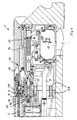
- a rifle 1 and 2 a rifle 1, namely a match air rifle with pre-compression, a handle 2, a barrel 3 with storey 4 at its rear end, and a movable one Closure part 5 on the closed from the shown Position yourself backwards (right in Fig. 1) in an open Position can shift.
- This is done automatically when a clamping lever 6 is pivoted to air with high To provide pressure by moving a compression piston 8.
- This causes a coupling with the tensioning lever 6
- Linkage 9 that there is a loading flap 10 around a Bolt 11 is pivotable, opening clockwise, which a tension spring 12 moves the closure piece 5 to the rear.
- the shooter can open the tailgate by hand if necessary. He closes them with his hand after loading this also closes the closure piece 5.
- the barrel 3 and a housing part 20, in which the bolt 11 and other weapon parts are arranged are not movable backwards relative to the handle 2. It is a weapon without a gun mount System.
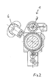
- Fig. 3 shows a view from above.
- the barrel 3 (Fig. 1) of the Gun closes with its storey 4, in the The diabolo bullet is to be inserted by hand at an air outlet 21 in the closure part 5, in which at Firing a shot of high pressure air through the Channel 19 is supplied, exits.
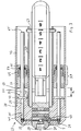
- Symmetrical to both Sides of the closure part 5 are two completely identical designs Pulse compensators arranged with respect an axis 29 of the barrel 3 diametrically opposite one another are arranged.
- Pulse compensators arranged with respect an axis 29 of the barrel 3 diametrically opposite one another are arranged.
- Pulse compensation device 27 another air duct 31, which is there in a channel 32 in extension of the further Air duct 31 continues.
- the channel 32 opens into a parallel to the axis 29 extending bore forming a gas cylinder 35, in which a compensation part 37 with a piston serving rod-like end part 39 slidably inserted is; the end part 39 carries at its front end region a piston seal 41 designed as an O-ring forms the seal against the wall of the bore 35.
- the two compensation parts 37 are in their front end position shown by the stop of a stop disc 43 on a stop surface 45 of the bore 35 containing part 28 is limited.
- a circular cylindrical tube 47 on its the closure part 5 facing side has a hole 49 attached.
- the Compensation part 37 has an axis with the end part 39 trained rod-shaped extension 51, which in the example makes up the main part of the mass of the compensation part 37.
- the extension 51 goes through essentially one hollow cylindrical, made of two parts 53, 55 and further compensation part formed between the O-ring 57 59 through.
- the parts 53 and 55 are by means of a thread 61 can be approached and removed relative to one another, and in a cavity formed between them, the reduced by mutually rotating the parts 53 and 55 or can be enlarged, the O-ring 57 is used and lies depending on the setting of parts 53 and 55 relative to each other with different forces on the outer wall the outer circular cylindrical extension 51 and thus forms an adjustable friction brake compared to this.
- the further compensation part 59 is in the tube 47 Slidable with little friction.
- the compensation devices 27 When the weapon is cocked by means of the cocking lever, the compensation devices 27 have been brought into the starting position shown in FIG. 3, in which the stop disc 43 bears against the part 28 and the further compensation part 59 is at a distance a from the surface of the stop disc 43 facing it.
- the compensation parts have been brought into this position in that when the tensioning lever is actuated, the closure piece moves backwards (because the loading flap 10 springs open) and the compensation devices are also moved backwards as a result.
- a transverse pin 63 which is immovable with respect to the handle 2 and which extends somewhat into the interior of the tubes 47 shifts the compensation parts into their starting position.
- the further compensation part 59 has a smaller distance from the stop disk 43 than from the free end 65 of the compensation part 37; the end 65 is located approximately where the cross bolt 63 is in the rest position of the tensioning lever.
- the compensation element 37 has been brought into its starting position, in which the stop disk 43 bears against the part 28.
- the cross pin 63 forms a limitation of the path that the further compensation part 59 when it moves backwards (to the right in Fig. 3).
- the arrangement is so made that the further compensation part 59 at the Firing either the cross bolt 63 not reached, but comes to a standstill beforehand due to frictional forces but still a long way to go with work with a relatively low friction relative to the tube 47 to be able to and thereby the effect on the hand of the shooter, which is transmitted via this frictional force. Or else the additional compensation part 59 comes along its backward movement on the cross pin 63 to the stop.
- Fig. 3 The operation of the arrangement shown in Fig. 3 is like follows. Starting from the position shown in Fig. 3, in who, as I said, the weapon is cocked and is ready to fire, with one bullet in the barrel, the shooter releases when the weapon is held horizontally, as in such weapons in general, the shot from.
- the high pressure air comes through the Air duct 19 and flows on the one hand in the barrel to there Drive the floor, on the other hand through the other air channels 31 and 32 in the end region of the holes 35, where they on the front end of the compensation part, which acts as a piston surface 37 hits. Because of its mass, which is considerably larger than that of the floor, with one thrown backward at a lower speed than that Bullet speed corresponds.
- the stop disc 43 hits the front surface 69 of part 53 of the further compensation part 59, in the example with an elastic push.
- the further compensation part 59 is provided with a larger mass than that in the example first-mentioned compensation part 37. Therefore, the former bounces Compensation part 37 back after there is a part its kinetic energy to the further compensation part 59 transferred. This moves it backwards.
- the just initiated movement of the first-mentioned compensation part 37 forward due to the friction of the O-ring 57 braked on the extension 59 this acts simultaneously Braking the movement of the further compensation part 59 opposite. It becomes part of the kinetic energy of the Compensation part and the further compensation part in Heat converted.
- the stop washer 43 at her after hitting the rest Compensation part 59 subsequent forward movement the part 28 no longer reached, but that all previously Parts have come to a standstill.
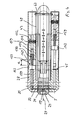
- the further exemplary embodiment shown in FIG. 4 differs 3 only with regard to the compensation parts, whose reference numerals in comparison to FIG. 3 100 are higher.
- a compensation part 137 engages with a rod 139 with a gas-tight fit without a separate sealing element and is displaceable in the bore 35 of the part 28.
- the rod-like extension 151 is shorter than in FIG. 3 and serves as a holder for a spring 170 designed as a helical compression spring, which is connected to the compensation part 137 and the further compensation part 159 in a tensile manner.
- the rod 151 goes without friction into a correspondingly large central recess in the further compensation part.
- the desired friction between the further compensation part 159 and the inner surface of the tube 47 is brought about by two friction pieces 171 made of plastic, which are arranged in a transverse bore 172 of the further compensation part 159 and are acted upon by a compression spring 173.
- the dimension a can be chosen in a suitable manner.
- the parts Before the shot is fired, the parts in the upper part of the Fig. 4 position shown. When the shot is fired, it moves first only the compensation part 137 to the rear, thereby tensioning the spring 170, so that thereby the further compensation part 159 is accelerated backwards before the former Compensation part hits. The spring 170 prevents such an encounter. After all the parts came to rest they have the position shown in the lower part of FIG. 4, in which the cross pin 63 acts as a stop. The pole 139 has not completely emerged from the bore 35. The parts are reset in a similar way as in Fig. 5a to 5c. The spring 170 brings the compensation part 137 in its initial position shown in FIG. 4 above.
- 5a to 5c show an arrangement with a compensation device which is only present on one side.
- 5a shows the arrangement with the weapon under tension before delivery of a shot, a floor 200 is shown for illustration.
- the compensation part is located on the front Attack.
- Fig. 5b shows the arrangement after the shot.
- the compensation part has moved backwards and is on the cross bolt 63 'came to the plant.
Landscapes
- Engineering & Computer Science (AREA)
- General Engineering & Computer Science (AREA)
- Toys (AREA)
- Glass Compositions (AREA)
- Magnetic Bearings And Hydrostatic Bearings (AREA)
Description
- Fig. 1
- einen Längsschnitt, teilweise abgebrochen, eines Luftgewehrs mit Vorkompression, das eine Kompensationsvorrichtung enthält,
- Fig. 2
- einen Querschnitt durch das Gewehr der Fig. 1, der den Spannhebel zeigt,
- Fig. 3
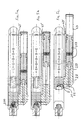
- in einem Längsschnitt eine erste Anordnung zum Kompensieren des Geschoßimpulses,
- Fig. 4
- in einem Längsschnitt eine zweite Anordnung zum Kompensieren des Geschoßimpulses, in zwei unterschiedlichen Stellungen.
- Fig. 5a bis 5c
- den prinzipiellen Ablauf der Kompensation.
Claims (16)
- Gasdruckwaffe, bei der beim Abgeben eines Schusses ein Geschoß (200) durch unter hohem Druck stehendes Gas aus einem Lauf (3) der Waffe getrieben wird, mit einem Vorratsbehälter für Kohlendioxid oder für Preßluft oder Waffe mit Vorkompression, mit einem Griff (2) zum Halten der Waffe mit mindestens einer Hand,
dadurch gekennzeichnet, daß die Waffe eine Kompensationsvorrichtung mit mindestens einem Kompensationsteil (37) aufweist, das durch den das Geschoß (200) antreibenden Gasdruck relativ zum Griff (2) in einer im wesentlichen zur Geschoßbewegungsrichtung entgegengesetzten Richtung antreibbar ist, derart, daß der auf den Griff (2) infolge der Bewegung des Geschosses (200) im Lauf einwirkende Impuls verringert ist, und daß das mindestens eine Kompensationsteil (37) relativ zum Lauf (3) beweglich ist. - Waffe nach Anspruch 1, dadurch gekennzeichnet, daß von einem Gaskanal, der den Gasdruck in den Bereich hinter dem Geschoßlager (in dem sich in schußbereiter Position ein Geschoß befindet) leitet, ein Kanal zu der Kompensationsvorrichtung führt.
- Waffe nach einem der vorhergehenden Ansprüche, dadurch gekennzeichnet, daß zwei Kompensationsteile (37) an einander gegenüberliegenden Seiten der Längsachse (29) des Laufs angeordnet sind.
- Waffe nach einem der vorhergehenden Ansprüche, dadurch gekennzeichnet, daß das Kompensationsteil (37) zumindest am Anfang seiner Bewegung weitgehend ungebremst ist.
- Waffe nach einem der vorhergehenden Ansprüche, dadurch gekennzeichnet, daß mindestens einem Kompensationsteil (37) ein beweglich angeordnetes weiteres Kompensationsteil (59) zugeordnet ist, das im Weg des zugehörigen Kompensationsteils (37) angeordnet ist, am Anfang der Bewegung des zugehörigen Kompensationsteils (37) von diesem einen Abstand aufweist und von diesem antreibbar ist, vorzugsweise mittels eines elastischen Elements, insbesondere einer Feder.
- Waffe nach Anspruch 5, dadurch gekennzeichnet, daß das weitere Kompensationsteil (59) durch mechanischen (elastischen oder unelastischen) Stoß antreibbar ist, wahlweise ohne Feder.
- Waffe nach einem der vorhergehenden Ansprüche, dadurch gekennzeichnet, daß eine Bremsvorrichtung (57) für das Kompensationsteil und/oder das weitere Kompensationsteil (59) vorgesehen ist.
- Waffe nach Anspruch 7, dadurch gekennzeichnet, daß die Bremsvorrichtung gegenüber einem waffenfesten Teil wirkt.
- Waffe nach Anspruch 7 oder 8, dadurch gekennzeichnet, daß die Bremsvorrichtung (57) gegenüber dem Kompensationsteil (37) wirkt.
- Waffe nach einem der Ansprüche 5 bis 9, dadurch gekennzeichnet, daß das weitere Kompensationsteil (59) eine größere Masse als das zugeordnete Kompensationsteil (37) hat.
- Waffe nach einem der vorhergehenden Ansprüche, dadurch gekennzeichnet, daß die Masse des Kompensationsteils (37) bzw. die Gesamtmasse aller Kompensationsteile (37) erheblich größer als die Masse des Geschosses ist.
- Waffe nach einem der vorhergehenden Ansprüche, dadurch gekennzeichnet, daß das Kompensationsteil (37) einen Kolben (Stange 39) aufweist, der abgedichtet in einer Bohrung (35) gleitet, deren eines Ende mit einem Gaskanal (23) in Verbindung steht, der das unter hohem Druck stehende Gas dem Inneren des Laufs zuführt.
- Waffe nach einem der vorhergehenden Ansprüche, dadurch gekennzeichnet, daß die Kompensationsvorrichtung ein Gehäuse aufweist, in dem das Kompensationsteil verschiebbar geführt ist.
- Waffe nach einem der vorhergehenden Ansprüche, dadurch gekennzeichnet, daß eine Rückstellvorrichtung vorgesehen ist, die die Kompensationsvorrichtung in einen vor Schußabgabe erforderlichen Ausgangszustand bringt.
- Waffe nach Anspruch 14, dadurch gekennzeichnet, daß ein zwischen einer offenen und einer geschlossenen Stellung bewegliches Verschlußteil vorgesehen ist, und daß die Rückstellvorrichtung mit dem Verschlußteil gekoppelt ist.
- Waffe nach einem der vorhergehenden Ansprüche, dadurch gekennzeichnet, daß ein zwischen einer offenen und einer geschlossenen Stellung bewegliches Verschlußteil vorgesehen ist, in dem ein Gaskanal vorhanden ist, durch den das Druckgas bei geschlossenem Verschlußteil zum Geschoßlager gelangt, und daß das Gehäuse der Kompensationsvorrichtung an dem Verschlußteil angeordnet und mit diesem beweglich ist.
Priority Applications (1)
| Application Number | Priority Date | Filing Date | Title |
|---|---|---|---|
| DE29721712U DE29721712U1 (de) | 1996-01-19 | 1997-01-15 | Gasdruckwaffe |
Applications Claiming Priority (2)
| Application Number | Priority Date | Filing Date | Title |
|---|---|---|---|
| DE19601864 | 1996-01-19 | ||
| DE19601864A DE19601864A1 (de) | 1996-01-19 | 1996-01-19 | Gasdruckwaffe |
Publications (3)
| Publication Number | Publication Date |
|---|---|
| EP0785405A2 EP0785405A2 (de) | 1997-07-23 |
| EP0785405A3 EP0785405A3 (de) | 1997-10-15 |
| EP0785405B1 true EP0785405B1 (de) | 1998-12-30 |
Family
ID=7783187
Family Applications (1)
| Application Number | Title | Priority Date | Filing Date |
|---|---|---|---|
| EP97100497A Expired - Lifetime EP0785405B1 (de) | 1996-01-19 | 1997-01-15 | Gasdruckwaffe |
Country Status (3)
| Country | Link |
|---|---|
| EP (1) | EP0785405B1 (de) |
| AT (1) | ATE175268T1 (de) |
| DE (2) | DE19601864A1 (de) |
Cited By (1)
| Publication number | Priority date | Publication date | Assignee | Title |
|---|---|---|---|---|
| DE102016203548B3 (de) * | 2016-03-03 | 2017-04-20 | Feinwerkbau GmbH | Druckluftwaffe mit Impulskompensation |
Families Citing this family (2)
| Publication number | Priority date | Publication date | Assignee | Title |
|---|---|---|---|---|
| DE102009011718B4 (de) * | 2009-03-04 | 2011-06-09 | Carl Walther Gmbh | Gasdruckbetriebene Schusswaffen-Vorrichtung |
| ITLU20120004A1 (it) * | 2012-02-27 | 2013-08-28 | Pardini Armi Srl | Arma a gas compresso con dispositivo di compensazione dell'impulso di sparo |
Family Cites Families (8)
| Publication number | Priority date | Publication date | Assignee | Title |
|---|---|---|---|---|
| DE952874C (de) * | 1953-12-17 | 1956-11-22 | Dianawerk Mayer & Grammelspach | Feder-Druckluftwaffe mit gegenlaeufigen Luftkolben |
| DE1246471B (de) * | 1960-04-30 | 1967-08-03 | J G Anschuetz G M B H | Luftgewehr |
| DE1857879U (de) * | 1962-02-26 | 1962-08-30 | J G Anschuetz G M B H | Luftgewehr. |
| DE2205973A1 (de) * | 1972-02-09 | 1973-08-16 | Walter Braig | Luftgewehr mit federdruck und massenausgleich durch zwei gegenlaeufige kolben |
| DE2329425C3 (de) * | 1973-06-08 | 1979-10-11 | J.G. Anschuetz Gmbh, 7900 Ulm | Druckluftschußwaffe, insbesondere Luftgewehr |
| DE2936883A1 (de) * | 1979-09-12 | 1981-04-02 | J.G. Anschütz GmbH, 7900 Ulm | Wettkampfschusswaffe, insbesondere rueckstossfreie druckluftschusswaffe oder handfeuerwaffe |
| EP0283104A1 (de) * | 1987-01-09 | 1988-09-21 | Utec B.V. | Abzugsmechanismus für Feuerwaffen |
| DE4122835A1 (de) * | 1991-07-10 | 1993-01-21 | Mayer Grammelspach Dianawerk | Rueckstossarme schusswaffe |
-
1996
- 1996-01-19 DE DE19601864A patent/DE19601864A1/de not_active Withdrawn
-
1997
- 1997-01-15 AT AT97100497T patent/ATE175268T1/de active
- 1997-01-15 EP EP97100497A patent/EP0785405B1/de not_active Expired - Lifetime
- 1997-01-15 DE DE59700060T patent/DE59700060D1/de not_active Expired - Lifetime
Cited By (1)
| Publication number | Priority date | Publication date | Assignee | Title |
|---|---|---|---|---|
| DE102016203548B3 (de) * | 2016-03-03 | 2017-04-20 | Feinwerkbau GmbH | Druckluftwaffe mit Impulskompensation |
Also Published As
| Publication number | Publication date |
|---|---|
| EP0785405A2 (de) | 1997-07-23 |
| DE59700060D1 (de) | 1999-02-11 |
| DE19601864A1 (de) | 1997-07-24 |
| EP0785405A3 (de) | 1997-10-15 |
| ATE175268T1 (de) | 1999-01-15 |
Similar Documents
| Publication | Publication Date | Title |
|---|---|---|
| EP0656518B1 (de) | Schusswaffe mit Rückstossabpufferung, insbesondere Faustfeuerwaffe | |
| DE4109777C2 (de) | ||
| EP1262728B1 (de) | Laserpistole und Verfahren zum Umrüsten einer Scharfschusspistole zur Laserpistole | |
| EP0071795B1 (de) | Automatische Handfeuerwaffe | |
| DE3505443C2 (de) | ||
| DE623261C (de) | Selbsttaetige Feuerwaffe, insbesondere Maschinengewehr, nach dem Gasdruckladeprinziparbeitend | |
| EP0785405B1 (de) | Gasdruckwaffe | |
| DE4406401C2 (de) | Selbstladewaffe | |
| DE19951536C1 (de) | Schußwaffe | |
| CH651381A5 (de) | Waffenvorlaufdaempfer fuer eine maschinenkanone mit keilverschluss. | |
| DE29721712U1 (de) | Gasdruckwaffe | |
| AT5727U1 (de) | Druckgasbetriebene schusswaffe mit rückstossbremse | |
| DE19839986B4 (de) | Druckgaswaffe mit Rückstoßausgleich | |
| AT405974B (de) | Druckgaswaffe mit rückstossdämpfer | |
| CH676881A5 (de) | ||
| DE3714464A1 (de) | Grosskaliber-pistole (faustfeuerwaffe) fuer das sportliche und "praktische" pistolenschiessen | |
| DE2313631A1 (de) | Verdichtungsmechanismus fuer druckluftwaffen | |
| DE2439571B2 (de) | Handfeuerwaffe | |
| DE102016203548B3 (de) | Druckluftwaffe mit Impulskompensation | |
| DE19815467A1 (de) | Einrichtung zur Reduktion von Mündungsknall und/oder zur zumindest teilweisen Umlenkung ausströmender Pulvergase | |
| DE10141120C1 (de) | Gebogener Lauf mit Versatz für Faust-, Hand- und Maschinenwaffen | |
| DE1146408B (de) | Automatische Handfeuerwaffe | |
| DE19747586A1 (de) | Gasdruckwaffe | |
| DE733069C (de) | Vorrichtung zum UEbungsschiessen mit Druckluft aus Steilfeuergeschuetzen aller Art, Minenwerfern, Granatschleudern o. dgl. | |
| DE3702228A1 (de) | Abzugsvorrichtung fuer eine tragbare schusswaffe |
Legal Events
| Date | Code | Title | Description |
|---|---|---|---|
| PUAI | Public reference made under article 153(3) epc to a published international application that has entered the european phase |
Free format text: ORIGINAL CODE: 0009012 |
|
| AK | Designated contracting states |
Kind code of ref document: A2 Designated state(s): AT CH DE FR GB IT LI |
|
| PUAL | Search report despatched |
Free format text: ORIGINAL CODE: 0009013 |
|
| AK | Designated contracting states |
Kind code of ref document: A3 Designated state(s): AT CH DE FR GB IT LI |
|
| 17P | Request for examination filed |
Effective date: 19971022 |
|
| 17Q | First examination report despatched |
Effective date: 19980415 |
|
| GRAG | Despatch of communication of intention to grant |
Free format text: ORIGINAL CODE: EPIDOS AGRA |
|
| GRAG | Despatch of communication of intention to grant |
Free format text: ORIGINAL CODE: EPIDOS AGRA |
|
| GRAH | Despatch of communication of intention to grant a patent |
Free format text: ORIGINAL CODE: EPIDOS IGRA |
|
| GRAH | Despatch of communication of intention to grant a patent |
Free format text: ORIGINAL CODE: EPIDOS IGRA |
|
| GRAA | (expected) grant |
Free format text: ORIGINAL CODE: 0009210 |
|
| AK | Designated contracting states |
Kind code of ref document: B1 Designated state(s): AT CH DE FR GB IT LI |
|
| REF | Corresponds to: |
Ref document number: 175268 Country of ref document: AT Date of ref document: 19990115 Kind code of ref document: T |
|
| REG | Reference to a national code |
Ref country code: CH Ref legal event code: EP |
|
| ITF | It: translation for a ep patent filed | ||
| GBT | Gb: translation of ep patent filed (gb section 77(6)(a)/1977) |
Effective date: 19990111 |
|
| REF | Corresponds to: |
Ref document number: 59700060 Country of ref document: DE Date of ref document: 19990211 |
|
| REG | Reference to a national code |
Ref country code: CH Ref legal event code: NV Representative=s name: PATENTANWAELTE SCHAAD, BALASS, MENZL & PARTNER AG |
|
| ET | Fr: translation filed | ||
| PLBE | No opposition filed within time limit |
Free format text: ORIGINAL CODE: 0009261 |
|
| STAA | Information on the status of an ep patent application or granted ep patent |
Free format text: STATUS: NO OPPOSITION FILED WITHIN TIME LIMIT |
|
| 26N | No opposition filed | ||
| REG | Reference to a national code |
Ref country code: FR Ref legal event code: ST |
|
| REG | Reference to a national code |
Ref country code: FR Ref legal event code: RN Ref country code: FR Ref legal event code: FC |
|
| REG | Reference to a national code |
Ref country code: GB Ref legal event code: IF02 |
|
| REG | Reference to a national code |
Ref country code: GB Ref legal event code: 732E |
|
| REG | Reference to a national code |
Ref country code: CH Ref legal event code: PUE Owner name: FEINWERKBAU WESTINGER & ALTENBURGER GMBH Free format text: GERAETEBAU GMBH#NECKARSTRASSE 43#78727 OBERNDORF (DE) -TRANSFER TO- FEINWERKBAU WESTINGER & ALTENBURGER GMBH#NECKARSTRASSE 43#78727 OBERNDORF (DE) |
|
| REG | Reference to a national code |
Ref country code: FR Ref legal event code: TP |
|
| REG | Reference to a national code |
Ref country code: FR Ref legal event code: PLFP Year of fee payment: 19 |
|
| PGFP | Annual fee paid to national office [announced via postgrant information from national office to epo] |
Ref country code: CH Payment date: 20150123 Year of fee payment: 19 |
|
| PGFP | Annual fee paid to national office [announced via postgrant information from national office to epo] |
Ref country code: AT Payment date: 20150114 Year of fee payment: 19 Ref country code: FR Payment date: 20150115 Year of fee payment: 19 Ref country code: GB Payment date: 20150123 Year of fee payment: 19 |
|
| REG | Reference to a national code |
Ref country code: DE Ref legal event code: R082 Ref document number: 59700060 Country of ref document: DE Representative=s name: KOHLER SCHMID MOEBUS PATENTANWAELTE PARTNERSCH, DE Ref country code: DE Ref legal event code: R081 Ref document number: 59700060 Country of ref document: DE Owner name: FEINWERKBAU GMBH, DE Free format text: FORMER OWNER: FEINWERKBAU WESTINGER & ALTENBURGER GMBH, 78727 OBERNDORF, DE |
|
| PGFP | Annual fee paid to national office [announced via postgrant information from national office to epo] |
Ref country code: DE Payment date: 20160129 Year of fee payment: 20 Ref country code: IT Payment date: 20160126 Year of fee payment: 20 |
|
| REG | Reference to a national code |
Ref country code: CH Ref legal event code: PL |
|
| REG | Reference to a national code |
Ref country code: AT Ref legal event code: MM01 Ref document number: 175268 Country of ref document: AT Kind code of ref document: T Effective date: 20160115 |
|
| GBPC | Gb: european patent ceased through non-payment of renewal fee |
Effective date: 20160115 |
|
| REG | Reference to a national code |
Ref country code: FR Ref legal event code: ST Effective date: 20160930 |
|
| PG25 | Lapsed in a contracting state [announced via postgrant information from national office to epo] |
Ref country code: GB Free format text: LAPSE BECAUSE OF NON-PAYMENT OF DUE FEES Effective date: 20160115 Ref country code: LI Free format text: LAPSE BECAUSE OF NON-PAYMENT OF DUE FEES Effective date: 20160131 Ref country code: CH Free format text: LAPSE BECAUSE OF NON-PAYMENT OF DUE FEES Effective date: 20160131 |
|
| PG25 | Lapsed in a contracting state [announced via postgrant information from national office to epo] |
Ref country code: FR Free format text: LAPSE BECAUSE OF NON-PAYMENT OF DUE FEES Effective date: 20160201 Ref country code: AT Free format text: LAPSE BECAUSE OF NON-PAYMENT OF DUE FEES Effective date: 20160115 |
|
| REG | Reference to a national code |
Ref country code: DE Ref legal event code: R071 Ref document number: 59700060 Country of ref document: DE |