EP0780225B1 - Verfahren zur Herstellung einer Kunststoffmaske für den Pastendruck und Kunststoffmaske für den Pastendruck - Google Patents
Verfahren zur Herstellung einer Kunststoffmaske für den Pastendruck und Kunststoffmaske für den Pastendruck Download PDFInfo
- Publication number
- EP0780225B1 EP0780225B1 EP96120634A EP96120634A EP0780225B1 EP 0780225 B1 EP0780225 B1 EP 0780225B1 EP 96120634 A EP96120634 A EP 96120634A EP 96120634 A EP96120634 A EP 96120634A EP 0780225 B1 EP0780225 B1 EP 0780225B1
- Authority
- EP
- European Patent Office
- Prior art keywords
- mask
- plastic
- mask plate
- adhesive
- frame
- Prior art date
- Legal status (The legal status is an assumption and is not a legal conclusion. Google has not performed a legal analysis and makes no representation as to the accuracy of the status listed.)
- Expired - Lifetime
Links
- 239000004033 plastic Substances 0.000 title claims abstract description 165
- 238000007639 printing Methods 0.000 title claims abstract description 90
- 238000004519 manufacturing process Methods 0.000 title claims abstract description 31
- 239000000853 adhesive Substances 0.000 claims description 78
- 230000001070 adhesive effect Effects 0.000 claims description 77
- 239000010409 thin film Substances 0.000 claims description 35
- 238000000034 method Methods 0.000 claims description 29
- 239000002985 plastic film Substances 0.000 claims description 13
- 239000011248 coating agent Substances 0.000 claims description 12
- 239000012790 adhesive layer Substances 0.000 claims description 8
- 238000000576 coating method Methods 0.000 claims description 7
- 239000010410 layer Substances 0.000 claims description 6
- 239000000463 material Substances 0.000 description 30
- 238000004026 adhesive bonding Methods 0.000 description 10
- 229920000728 polyester Polymers 0.000 description 10
- 229910052751 metal Inorganic materials 0.000 description 8
- 239000002184 metal Substances 0.000 description 8
- 230000001681 protective effect Effects 0.000 description 8
- 230000013011 mating Effects 0.000 description 7
- ZWEHNKRNPOVVGH-UHFFFAOYSA-N 2-Butanone Chemical compound CCC(C)=O ZWEHNKRNPOVVGH-UHFFFAOYSA-N 0.000 description 6
- 239000004593 Epoxy Substances 0.000 description 6
- 229910052782 aluminium Inorganic materials 0.000 description 6
- XAGFODPZIPBFFR-UHFFFAOYSA-N aluminium Chemical compound [Al] XAGFODPZIPBFFR-UHFFFAOYSA-N 0.000 description 6
- 238000006073 displacement reaction Methods 0.000 description 5
- 238000005520 cutting process Methods 0.000 description 4
- 230000000873 masking effect Effects 0.000 description 4
- 238000005299 abrasion Methods 0.000 description 3
- 238000005452 bending Methods 0.000 description 2
- 230000006866 deterioration Effects 0.000 description 2
- 239000003085 diluting agent Substances 0.000 description 2
- 238000005530 etching Methods 0.000 description 2
- 239000011521 glass Substances 0.000 description 2
- 238000009434 installation Methods 0.000 description 2
- 229920005989 resin Polymers 0.000 description 2
- 239000011347 resin Substances 0.000 description 2
- 238000007650 screen-printing Methods 0.000 description 2
- 229910000679 solder Inorganic materials 0.000 description 2
- 239000004677 Nylon Substances 0.000 description 1
- 239000000654 additive Substances 0.000 description 1
- 230000000996 additive effect Effects 0.000 description 1
- 230000008021 deposition Effects 0.000 description 1
- 238000005553 drilling Methods 0.000 description 1
- 230000000694 effects Effects 0.000 description 1
- 230000008030 elimination Effects 0.000 description 1
- 238000003379 elimination reaction Methods 0.000 description 1
- 229920006332 epoxy adhesive Polymers 0.000 description 1
- 239000010408 film Substances 0.000 description 1
- 238000012986 modification Methods 0.000 description 1
- 230000004048 modification Effects 0.000 description 1
- 229920001778 nylon Polymers 0.000 description 1
- 238000003825 pressing Methods 0.000 description 1
- 238000005406 washing Methods 0.000 description 1
Images


Classifications
-
- G—PHYSICS
- G03—PHOTOGRAPHY; CINEMATOGRAPHY; ANALOGOUS TECHNIQUES USING WAVES OTHER THAN OPTICAL WAVES; ELECTROGRAPHY; HOLOGRAPHY
- G03F—PHOTOMECHANICAL PRODUCTION OF TEXTURED OR PATTERNED SURFACES, e.g. FOR PRINTING, FOR PROCESSING OF SEMICONDUCTOR DEVICES; MATERIALS THEREFOR; ORIGINALS THEREFOR; APPARATUS SPECIALLY ADAPTED THEREFOR
- G03F1/00—Originals for photomechanical production of textured or patterned surfaces, e.g., masks, photo-masks, reticles; Mask blanks or pellicles therefor; Containers specially adapted therefor; Preparation thereof
- G03F1/62—Pellicles, e.g. pellicle assemblies, e.g. having membrane on support frame; Preparation thereof
- G03F1/64—Pellicles, e.g. pellicle assemblies, e.g. having membrane on support frame; Preparation thereof characterised by the frames, e.g. structure or material, including bonding means therefor
-
- H—ELECTRICITY
- H05—ELECTRIC TECHNIQUES NOT OTHERWISE PROVIDED FOR
- H05K—PRINTED CIRCUITS; CASINGS OR CONSTRUCTIONAL DETAILS OF ELECTRIC APPARATUS; MANUFACTURE OF ASSEMBLAGES OF ELECTRICAL COMPONENTS
- H05K3/00—Apparatus or processes for manufacturing printed circuits
- H05K3/10—Apparatus or processes for manufacturing printed circuits in which conductive material is applied to the insulating support in such a manner as to form the desired conductive pattern
- H05K3/12—Apparatus or processes for manufacturing printed circuits in which conductive material is applied to the insulating support in such a manner as to form the desired conductive pattern using thick film techniques, e.g. printing techniques to apply the conductive material or similar techniques for applying conductive paste or ink patterns
- H05K3/1216—Apparatus or processes for manufacturing printed circuits in which conductive material is applied to the insulating support in such a manner as to form the desired conductive pattern using thick film techniques, e.g. printing techniques to apply the conductive material or similar techniques for applying conductive paste or ink patterns by screen printing or stencil printing
- H05K3/1225—Screens or stencils; Holders therefor
-
- B—PERFORMING OPERATIONS; TRANSPORTING
- B41—PRINTING; LINING MACHINES; TYPEWRITERS; STAMPS
- B41C—PROCESSES FOR THE MANUFACTURE OR REPRODUCTION OF PRINTING SURFACES
- B41C1/00—Forme preparation
- B41C1/14—Forme preparation for stencil-printing or silk-screen printing
-
- B—PERFORMING OPERATIONS; TRANSPORTING
- B41—PRINTING; LINING MACHINES; TYPEWRITERS; STAMPS
- B41F—PRINTING MACHINES OR PRESSES
- B41F15/00—Screen printers
- B41F15/14—Details
- B41F15/34—Screens, Frames; Holders therefor
- B41F15/36—Screens, Frames; Holders therefor flat
-
- G—PHYSICS
- G03—PHOTOGRAPHY; CINEMATOGRAPHY; ANALOGOUS TECHNIQUES USING WAVES OTHER THAN OPTICAL WAVES; ELECTROGRAPHY; HOLOGRAPHY
- G03F—PHOTOMECHANICAL PRODUCTION OF TEXTURED OR PATTERNED SURFACES, e.g. FOR PRINTING, FOR PROCESSING OF SEMICONDUCTOR DEVICES; MATERIALS THEREFOR; ORIGINALS THEREFOR; APPARATUS SPECIALLY ADAPTED THEREFOR
- G03F1/00—Originals for photomechanical production of textured or patterned surfaces, e.g., masks, photo-masks, reticles; Mask blanks or pellicles therefor; Containers specially adapted therefor; Preparation thereof
- G03F1/38—Masks having auxiliary features, e.g. special coatings or marks for alignment or testing; Preparation thereof
Definitions
- This invention relates to a mask unit for paste printing for forming patterns by use of an ink, an adhesive, solder paste, or a paste-like resin on a printing material, and more particularly to a plastic mask unit which has a long life and is capable of performing paste printing of a superior quality.
- This invention also relates to a method of fabricating the above-mentioned plastic mask unit.
- an example of conventional printing masks for the paste printing is a mask known as a punch press mask which can be prepared by forming round through-holes in a metal sheet with a punch.
- a YAG laser mask which can be prepared by forming through-holes in a metal sheet with a YAG laser.
- an etching mask which can be prepared by forming through-holes in a metal sheet using a metal etching process.
- an additive mask which can be prepared by forming through-holes in a metal plate formed by being plated around a pattern of through-holes.
- a mask made of a plastic sheet has been recently introduced which is disclosed in JP-A-7-81027.
- This plastic mask can be prepared by forming slit-shaped through-holes in a plastic sheet by excimer laser abrasion.
- the plastic mask becomes free from various known shortcomings, such as, for example, burr in the edges of the through-holes, deposition of dross in the through-holes, and so forth, that occur in the conventional metal masks.
- such a plastic mask meets increasing demands for highly precise paste printing of a micro pattern with high quality, which arise from the recent trend whereby electronic appliances and parts are made smaller and smaller in size.
- JP-A-1-255536 discloses a screen printing plate which is produced by cutting a glass epoxy material in the size of a screen printing plate, drilling through-holes in a pattern figure in the screen material, thus manufacturing a screen plate, and fastening the screen plate to a screen frame.
- the glass epoxy material employed as a screen material is however disadvantageous as it lacks elastic properties.
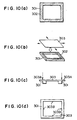
- reference numeral 301 denotes a mask frame to which a rectangular croos section aluminum pipe is commonly adopted.
- Such an aluminum mask frame is coated with a coating agent suitable for gluing aluminum so that a first thin film 302 suitable for gluing aluminum is formed in a square frame on the edge of the mask frame 301 as shown in Figure 10(a).
- a rubber adhesive diluted with a diluent is commonly applied to this coating material.
- a rough finish may be provided to the edge of the mask frame 301 before the first thin film 302 is formed thereon.
- a mesh screen 303 is coated with a coating material suitable for gluing polyester, for example, so that a second thin film suitable for gluing polyester is formed in a square frame on the mesh screen 303.
- a polyester mesh screen of about 180 to 225 mesh or a nylon mesh screen of about 180 to 225 mesh can be applied.
- an adhesive is an epoxy type adhesive which is suitable for gluing both the first thin film formed on the mask frame 301 and the second thin film formed on the polyester mesh screen 303.
- an epoxy adhesive is coated on either one or both of the first thin film formed on the mask frame 301 and the second thin film formed on the polyester mesh screen 303.
- the mesh screen 303 is secured to the mask frame 301 as shown in Figure 10(c). Since, in addition to extension caused by the predetermined tension, the mesh screen 303 is prepared in a predetermined size larger than the mask frame 301, there are overhanging edges 303a of the mesh screen relative to the periphery of the mask frame 301 as shown in Figure 10(c). Accordingly, these overhanging edges 303a of the mesh screen 303 are cut off so that the mesh screen 303 becomes equal in size to the mask frame 301 in the horizontal plain in the drawing.
- FIG. 10(d) a step of drawing register marks for accurately registering the mesh screen relative to the mask plate is shown in Figure 10(d).
- a register mark 303b is drawn at the centers of all four sides of the mesh screen 303 secured to the mask frame 301.
- the register marks 303b are drawn softly and visibly using a sharp-pointed pencil on the mesh screen 303 so that the mask plate 304 can be accurately registered relative to the mesh screen 303 in the following step.
- the mask plate 304 is then coated with a coating agent as shown in Figure 10(e).
- This mask plate 304 includes a number of slit-shaped through-holes for serving as a print pattern for paste printing.
- the edge of the mask plate 104 is coated with a coating agent suitable for gluing the mask plate 304.
- a thin film 304b suitable for gluing the mask plate 304 is formed.
- the mask plate 304 is secured to the mesh screen 303.
- a rubber type adhesive diluted with a diluent is usually applied to the coating agent.
- edge frame of the mesh screen 303 may be coated with another coating agent suitable for gluing polyester, for example, so that a polyester thin film suitable for gluing polyester can be formed on the edge frame of the mesh screen 303.
- a rough finish or a number of fine holes may be provided at the edge of the mask plate 304 before the thin film 304b is formed thereon.
- the step of securing the mask plate 304 to the mesh screen 303 on the mask frame 301 is shown in Figure 10(f).
- the position of the mask plate 304 on the mesh screen 303 is manually adjusted so that center holes 304c on each side of the mask plate 304 and the register marks 303b of the mesh screen 303 can be finely registered.
- the mask plate 304 is temporarily taped to the mask frame 301 and the mesh screen 303 to form an integrated unit.
- this one unit of the mask frame 301, the mesh screen 303, and the mask plate 304 is turned upside down and masking tape is placed over a relatively large area of the mesh screen 303, leaving an area in the form of a square frame to be coated with adhesive, while the taped area is not coated with the adhesive.
- This masking tape must be in place before an epoxy type adhesive, for example, is coated onto the square frame of the mesh screen 303. The masking tape is removed after the adhesive is cured on the mesh screen 303.
- the step of making an opening 303c is explained in Figure 10(g).
- the opening 303c is formed by cutting out the mesh screen 303.
- the area cut must not be secured by the mask plate 304 so that a portion 305 in which the adhesive is cured on the mesh screen 303 can be left.
- each glued portion is provided with guard tapes to prevent peeling-off so that the mask frame 301 and the mesh screen 303, the mask plate 304 and the mesh screen 303 are mutually secured.
- the conventional mask unit for paste printing is fabricated. Consequently, the thus fabricated printing mask unit has a three-layer structure wherein the mask frame 301 and the mask plate 304 are secured with the mesh screen 303 inserted in between, as shown in Figures 10(g) and 10(h).
- an object of the present invention is to provide a novel plastic mask unit for paste printing which is superior in accurate registration of a print pattern thereof relative to a printing material and capable of performing paste printing with superior printing quality.
- Another object of the present invention is to provide a novel plastic mask unit for paste printing which has a relatively long life and is therefore capable of performing paste printing for a relatively large number of times.
- Another object of the present invention is to provide a novel plastic mask unit for paste printing which is fabricated in a relatively small number of fabrication steps.
- Another object of the present invention is to provide a novel plastic mask unit for paste printing which is installed in a relatively small number of installation steps on a paste printing machine.
- Another object of the present invention is to provide a method of fabricating the above-mentioned novel plastic mask unit for paste printing.
- a mask unit for paste printing according to the present invention is a plastic mask unit which includes a mask frame and a mask plate including a plastic sheet formed with a plurality of slit-shaped through-holes therein for serving as a print pattern for paste printing, and wherein the mask plate is secured directly to the mask frame.
- the mask plate is secured directly to the mask frame with at least one adhesive.
- the above-mentioned adhesive includes three adhesive layers, a first adhesive layer which is suitable for adhering to the mask frame and placed on the mask frame side, a second adhesive layer which is suitable for adhering to the mask plate and placed on the mask plate side, and a third adhesive layer which is suitable for adhering to the first and second layers and placed between the first and second layers.
- the above-mentioned mask frame is secured to a first adhesive thin film suitable for adhering the mask frame
- the mask plate is secured to a second adhesive thin film suitable for adhering to the mask plate
- the mask frame and the mask plate are secured together by an adhesive suitable for adhering to the first and second adhesive thin films.
- the above-mentioned mask plate includes a plastic sheet which is formed with a plurality of slit-shaped through-holes for serving as a print pattern for paste printing by using an excimer laser.
- a method of fabricating a plastic mask unit, which includes a mask frame and a mask plate including a plastic sheet, for paste printing, according to the present invention includes steps of securing the mask plate directly to the mask frame and then forming the mask plate with a plurality of slit-shaped through-holes for serving as a print pattern for paste printing.
- the step of securing the mask plate directly to the mask frame including steps of coating a first adhesive, suitable for adhering to the mask frame, on the surface of the mask frame, coating a second adhesive, suitable for adhering to the mask plate, on the surface of the mask plate, and then securing the mask plate directly to the mask frame by a third adhesive suitable for adhering to the first and second adhesives.
- the above-mentioned step of securing the mask plate directly to the mask frame including steps of securing the mask frame to a first adhesive thin film suitable for adhering to the mask frame, securing the mask plate to a second adhesive thin film suitable for adhering to the mask plate, and then securing the mask plate directly to the mask frame with an adhesive suitable for adhering to the first and second adhesive thin films.
- the step of forming the mask is carried out by using an excimer laser.
- the plastic mask unit for paste printing can be made superior in accurate registration of slit-shaped through-holes thereof relative to a printing material and therefore capable of performing the paste printing with superior printing quality.
- a plastic mask plate including a plurality of slit-shaped through-holes therein is secured directly to a mask frame.
- Such an arrangement subsequently provides an effect whereby the plastic mask plate can be kept in a plane shape by its own elasticity even with less tension provided from the outside, in comparison with the case of using a mesh screen. Accordingly, such tension provided from the outside to the plastic mask plate can be reduced and, subsequently, the amount of extension of the plastic mask plate can be reduced.
- the plastic mask unit can improve the printing quality in the manner mentioned above.
- the plastic mask plate can be set in relatively close contact relative to the printing material, with the tension provided from the outside being reduced. Thereby, the plastic mask unit can perform fine paste printing in which less blurs occur.
- the plastic mask unit for paste printing according to the present invention is free from displacement of the slit-shaped through-holes relative to the printing material. Accordingly, the plastic mask unit for paste printing according to the present invention provides superior accuracy in the registration of slit-shaped through-holes relative to the printing material and, subsequently, becomes capable of performing paste printing with superior printing quality.
- the mating faces of the plastic mask plate and the mask frame can be made in a relatively large size, approximately 40 mm in width, for example, while those of the conventional mask unit can be made approximately 10 mm to 15 mm in width, for example.
- the capability of making such large-sized mating faces also supports the above-mentioned explanation that damage to the plastic mask unit due to peeling of the mating faces is rarely caused. Accordingly, the plastic mask unit according to the present invention becomes capable of performing paste printing with superior printing quality.
- the plastic mask unit according to the present invention can be used for a relatively large number of times over a relatively long life span without damage from peeling of the mating faces.
- a method of fabricating the plastic mask unit for paste printing can reduce the number of fabrication steps in comparison with the number of fabrication steps for the conventional mask unit. This is due to an arrangement whereby a mask plate is secured directly to a mask frame and a mesh screen is eliminated from the structural elements of the conventional mask unit. Accordingly, various fabrication steps, such as, for example, the step of securing the mesh screen to the mask frame, the step of securing the mask plate to the mesh screen, the step of cutting out a middle portion of the mesh screen, the step of securing a protective tape on mating portions of the mesh screen and the mask plate, and so forth, are eliminated. Moreover, the above-mentioned method of fabricating the plastic mask unit for paste printing can reduce the fabrication cost in view of not only fabrication hours but also elimination of parts.
- the plastic mask plate formed with a plurality of slit-shaped through-holes therein for serving as a print pattern for paste printing, directly to the mask frame.
- an adhesive which is suitable for adhering to both of the materials of the plastic mask plate and the mask frame.
- the mask frame and the plastic mask plate can be tightly secured by providing a rough finish on the surfaces of either or both of the mask frame and the plastic mask plate, or by forming a relatively large number of fine holes in the surface of the plastic mask plate.
- the method of fabricating the plastic mask unit for paste printing can eliminate displacement of a print pattern including a plurality of slit-shaped through-holes relative to the printing material. Accordingly, this method of fabricating the plastic mask unit can provide a plastic mask unit which is capable of performing paste printing with superior quality. This is due to an arrangement whereby a plastic mask unit is subjected to a fabrication step of forming a plastic mask plate with a plurality of slit-shaped through-holes for serving as a print pattern for paste printing after the plastic mask unit has been fabricated in a semifinished form by securing the plastic mask plate directly to the mask frame without the forming process.
- the plastic mask unit fabricated by the above-mentioned method can perform fine paste printing with superior quality. Moreover, in such plastic mask unit fabricated by the above-mentioned method, steps of adjusting the position of the plastic mask unit in the paste printing machine can be eliminated.
- plastic mask unit fabricating method there are preferable methods for securing the plastic mask plate, formed with no print pattern, directly to the mask frame.
- an adhesive which is suitable for adhering to both the materials of the plastic mask plate and the mask frame.
- the mask frame and the plastic mask plate can be tightly secured by providing a rough finish on the surfaces of either or both of the mask frame and the plastic mask plate, or by forming a relatively large number of fine holes in the surface of the plastic mask plate.
- the plastic mask plate with a plurality of slit-shaped through-holes therein for serving as a print pattern for paste printing by excimer laser abrasion.
- FIG. 1 there is illustrated a sectional view of an example of a novel plastic mask unit 100' for paste printing including a mask frame 1 and a mask plate 4', made of a plastic sheet including a plurality of slit-shaped through-holes therein for serving as a print pattern for paste printing, for performing as a print mask, and wherein such a plastic mask plate 4' is secured directly to the mask frame 1.
- a thin film of an adhesive 2 is formed between the mask frame 1 and the plastic mask plate 4', by which the plastic mask plate 4' is secured directly to the mask frame 1 as shown in Figure 1.
- Such an adhesive 2 has a three-layer structure including a first adhesive 21 adhering to a mask frame 1 side, a second adhesive 22 adhering to a plastic mask plate 4' side, and a third adhesive 23 securing the first adhesive 21 to the second adhesive 22. Accordingly, the mask frame 1 is secured to an upper surface 4A' of the plastic mask plate 4'.
- reference numeral 4B' in Figure 1 denotes the bottom surface of the plastic mask plate 4'.
- the plastic mask unit 100 represents a semifinished form of the plastic mask unit 100', since the plastic mask plate 4 is in a form expected to be formed with a plurality of through-holes therein for serving as a print pattern for paste printing. Accordingly, the plastic mask unit 100 becomes the plastic mask 100' when the plastic mask plate 4 is formed with a plurality of through-holes therein for serving as a print pattern for paste printing.
- a rubber type adhesive is diluted with methylethylketone and coated onto a portion of the aluminum square pipe mask frame 1, on which the plastic mask plate 4 is placed, so as to form a thin film of the first adhesive 21 after the adhesive has dried.
- a rubber type adhesive is diluted with methylethylketone and coated onto a portion of the plastic mask plate 4, on which the mask frame 1 is placed, so- as to form a thin film of the second adhesive 22 after the adhesive has dried.
- an epoxy type adhesive as the third adhesive is coated onto the surface of the thin film made of the first adhesive 21 secured to the mask frame 1 and the surface of the thin film made of the second adhesive 22 secured to the plastic mask plate 4.
- the rubber type adhesive is used as an adhesive suitable for adhering to the aluminum square pipe mask frame 1 and the plastic mask plate 4 and the epoxy type adhesive is used as an adhesive suitable for adhering to the thin films made of the rubber type adhesive
- other types of adhesives suitable for adhering the mask frame, the plastic mask plate, and thin films made of these adhesives, respectively, may be used.
- each of the four sides of the plastic mask plate 4 is equally subjected to a predetermined tension along the whole length of each side by tension members 5 in the directions indicated by the arrows in Figure 3 and in the forward and reverse directions along an axis perpendicular to the drawing.
- This application of the predetermined tension to the sides of the plastic mask plate 4 is carried out while the plastic mask plate 4 is being placed and secured to the mask frame 1.
- the adhesive 2 is subsequently formed into a film between these two elements. Only after the adhesive 2 is cured, the tension members 5 are removed from the plastic mask plate 4.
- the plastic mask 4 Since, in addition to an extension made by the tension members 5, the plastic mask 4 is prepared in a predetermined size larger than that of the mask frame 1, there are overhanging edges 4C of the plastic mask plate 4 relative to the periphery of the mask frame 1. Accordingly, these excess edge sides 4C of the plastic mask plate 4 are cut off so that the plastic mask plate 4 becomes equal to the mask frame 1 in size in the horizontal plane on the drawing.
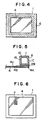
- FIGs 4 and 5 an area in which the plastic mask plate 4 is secured to the mask frame 1 may be protected from peeling by being taped with a protective tape 6.
- Figure 4 shows a top plan view of the plastic mask unit 100 with the protective tape 6 in place
- Figure 5 shows a sectional view of this.
- the placement of the protective tape 6 in Figures 4 and 5 may be made in the order of the bottom surface 4B for a length longer than the pipe width of the mask frame 1, an edge 4D of the plastic mask plate 4, an edge 2A of the adhesive 2, a side surface 1A of the mask frame 1, an upper surface 1B of the mask frame 1, an inner surface 1C of the mask frame 1, and the upper surface 4A of the plastic mask plate 4.
- the placement of the protective tape 6 may be made in the reverse order.
- the adhesion strength of the adhesive 2 is relatively insufficient, it is preferable to provide a rough finish to the surfaces of the mask frame 1 and the mask plate 4 to which adhesion is made, during the process of applying adhesives. It is also preferable to provide a large number of fine holes in the surface of the mask plate 4.
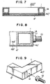
- the plastic mask unit After completing the placement of the protective tape in the above-mentioned manner, the plastic mask unit is subjected to irradiation by an excimer laser beam so that the plastic mask plate 4 thereof is formed with a plurality of slit-shaped through-holes 7 therein for serving as a print pattern for paste printing. Consequently, the fabrication procedure is ended and, as a result, there is fabricated one plastic mask unit 100' according to the present invention as shown in Figure 6, which is equivalent to the one shown in Figure 1.
- a plastic mask unit 200' shown in Figure 7 is fabricated in a manner similar to the plastic mask unit 100' shown in Figure 1, except for a process in which an edge 4C' of a plastic mask plate 4' of the plastic mask unit 200' is bent so as to be secured to an outer side 1A of a mask frame 1, in order to protect the plastic mask plate 4' and the mask frame 1 from peeling. More specifically, the edge 4C' of the plastic mask plate 4' is bent along the outer side 1A of the mask frame 1, while being outwardly subjected to a predetermined tension by the tension members 5 described hereinbefore, so that the mask frame 1 and the plastic mask plate 4' are firmly secured. In the above-mentioned bending process, the bending may be made at two opposite edges 4C' of the plastic mask plate 4', although it is preferable to bend all four edges 4C' of the plastic mask plate 4'.
- a plastic mask unit is supported by clamps in a paste printing machine during an operation.
- a clamp 10 shown in Figure 8 must be attached in a way so as not to damage any part of the edges 4C' of the plastic mask plate 4'. This is because registration of the plastic mask unit 200' with respect to a printing material becomes inaccurate due to abrasion of the edges 4C' of the plastic mask plate 4' if a holding part 11 of each clamp 10 holds the plastic mask unit 200' by pressing the edges 4C' of the plastic mask plate 4' as shown in Figure 8.
- the edges 4C' of the plastic mask plate 4' may be provided with a cut-out 12 as shown in Figure 9. In this way, the edges 4C' of the plastic mask plate 4' are not abraded by contact with the clamps 10 and, therefore, registration of the plastic mask unit 200' with respect to the printing material is not made inaccurate because of the clamps 10.
Landscapes
- Engineering & Computer Science (AREA)
- Manufacturing & Machinery (AREA)
- Microelectronics & Electronic Packaging (AREA)
- Mechanical Engineering (AREA)
- Physics & Mathematics (AREA)
- General Physics & Mathematics (AREA)
- Printing Plates And Materials Therefor (AREA)
- Manufacture Or Reproduction Of Printing Formes (AREA)
- Screen Printers (AREA)
- Manufacturing Of Printed Wiring (AREA)
- Inks, Pencil-Leads, Or Crayons (AREA)
Claims (7)
- Kunststoffmaskeneinheit für den Pastendruck umfassend:einen Maskenrahmen undeine Maskenplatte umfassend eine Kunststoffplatte mit elastischen Eigenschaften, die mit einer Mehrzahl von schlitzförmigen Durchgangslöchern, die als Druckmuster für den Pastendruck dienen, gebildet und direkt an dem Maskenrahmen mit einem Klebstoff befestigt ist, der drei Klebschichten umfasst, eine erste Klebschicht, die sich zum Anhaften an dem Maskenrahmen eignet und auf der Maskenrahmen-Seite angeordnet ist, eine zweite Klebschicht, die sich zum Anhaften an der Maskenplatte eignet und auf der Maskenplatten-Seite angeordnet ist, und eine dritte Klebschicht, die sich zum Anhaften an der ersten und zweiten Schicht eignet und zwischen der ersten und zweiten Schicht angeordnet ist.
- Kunststoffmaskeneinheit für den Pastendruck umfassend:einen Maskenrahmen undeine Maskenplatte umfassend eine Kunststoffplatte mit. elastischen Eigenschaften, die mit einer Mehrzahl von schlitzförmigen Durchgangslöchern, die als Druckmuster für den Pastendruck dienen, gebildet und direkt an dem Maskenrahmen befestigt ist, wobei der Maskenrahmen an einem ersten dünnen Klebstofffilm befestigt ist, der sich zum Anhaften an dem Maskenrahmen eignet, die Maskenplatte an einem zweiten dünnen Klebstofffilm befestigt ist, der sich zum Anhaften an der Maskenplatte eignet, und der Maskenrahmen und die Maskenplatte durch einen Klebstoff aneinander befestigt sind, der sich zum Anhaften an dem ersten und zweiten dünnen Klebstofffilm eignet.
- Kunststoffmaskeneinheit nach irgendeinem der Ansprüche 1 oder 2, worin die Maskenplatte eine Kunststoffplatte umfasst, die mit einer Mehrzahl von schlitzförmigen Durchgangslöchern, die als Druckmuster für den Pastendruck dienen, unter Verwendung eines Excimer-Lasers versehen worden ist.
- Verfahren zur Herstellung einer Kunststoffmaske für den Pastendruck nach Anspruch 1 oder 2, welches umfasst die Schritte:zuerst Befestigen der Maskenplatte umfassend eine Kunststoffplatte mit elastischen Eigenschaften direkt an dem Maskenrahmenund dann Versehen der Maskenplatte mit einer Mehrzahl von schlitzförmigen Durchgangslöchern, die als Druckmuster für den Pastendruck dienen.
- Verfahren nach Anspruch 4, worin der Schritt der direkten Befestigung der Maskenplatte an dem Maskenrahmen folgende Schritte umfasst:Auftragen eines ersten Klebstoffs, der sich zum Anhaften an dem Maskenrahmen eignet, auf eine Oberfläche des Maskenrahmens,Auftragen eines zweiten Klebstoffs, der sich zum Anhaften an der Maskenplatte eignet, auf eine Oberfläche der Maskenplatte undBefestigen der Maskenplatte direkt an dem Maskenrahmen durch einen dritten Klebstoff, der sich zum Anhaften an dem ersten und zweiten Klebstoff eignet.
- Verfahren nach Anspruch 4, worin der Schritt der direkten Befestigung der Maskenplatte an dem Maskenrahmen folgende Schritte umfasst:Befestigen des Maskenrahmens an einem ersten dünnen Klebstofffilm, der sich zum Anhaften an dem Maskenrahmen eignet,Befestigen der Maskenplatte an einem zweiten dünnen Klebstofffilm, der sich zum Anhaften an der Maskenplatte eignet, undBefestigen der Maskenplatte direkt an dem Maskenrahmen mit einem Klebstoff, der sich zum Anhaften an dem ersten und den zweiten dünnen Klebstofffilm eignet.
- Verfahren nach irgendeinem der Ansprüche 4 bis 6, worin der Schritt der Bildung der Maske mit einem Excimer-Laser durchgeführt wird.
Applications Claiming Priority (3)
| Application Number | Priority Date | Filing Date | Title |
|---|---|---|---|
| JP333185/95 | 1995-12-21 | ||
| JP33318595 | 1995-12-21 | ||
| JP33318595 | 1995-12-21 |
Publications (2)
| Publication Number | Publication Date |
|---|---|
| EP0780225A1 EP0780225A1 (de) | 1997-06-25 |
| EP0780225B1 true EP0780225B1 (de) | 2003-05-02 |
Family
ID=18263259
Family Applications (1)
| Application Number | Title | Priority Date | Filing Date |
|---|---|---|---|
| EP96120634A Expired - Lifetime EP0780225B1 (de) | 1995-12-21 | 1996-12-20 | Verfahren zur Herstellung einer Kunststoffmaske für den Pastendruck und Kunststoffmaske für den Pastendruck |
Country Status (6)
| Country | Link |
|---|---|
| US (1) | US6286424B1 (de) |
| EP (1) | EP0780225B1 (de) |
| KR (1) | KR100227917B1 (de) |
| AT (1) | ATE238908T1 (de) |
| DE (1) | DE69627794D1 (de) |
| TW (1) | TW342365B (de) |
Families Citing this family (5)
| Publication number | Priority date | Publication date | Assignee | Title |
|---|---|---|---|---|
| US7866261B2 (en) * | 2007-05-23 | 2011-01-11 | Rapid Screen Products Corporation | Metal stencil foil attachment to screen mesh |
| CN101318401B (zh) * | 2007-06-08 | 2010-12-29 | 富葵精密组件(深圳)有限公司 | 印刷网版及其制作方法 |
| CN104451538B (zh) * | 2014-12-30 | 2017-06-06 | 合肥鑫晟光电科技有限公司 | 掩膜板及其制作方法 |
| CN114055916B (zh) * | 2021-11-12 | 2022-05-03 | 广东方舟智造科技有限公司 | 键盘电路薄膜的遮光层印刷成型设备与方法 |
| DE102022203815A1 (de) | 2022-04-19 | 2023-10-19 | Robert Bosch Gesellschaft mit beschränkter Haftung | Verfahren zum Beschichten einer Verteilerplatte für eine elektrochemische Zelle |
Family Cites Families (35)
| Publication number | Priority date | Publication date | Assignee | Title |
|---|---|---|---|---|
| US3435758A (en) * | 1966-03-02 | 1969-04-01 | Dymo Industries Inc | Stencil and method of making the same |
| US3934503A (en) * | 1967-06-26 | 1976-01-27 | Iit Research Institute | Stencil screens |
| US3668028A (en) * | 1970-06-10 | 1972-06-06 | Du Pont | Method of making printing masks with high energy beams |
| CA1049312A (en) * | 1974-01-17 | 1979-02-27 | John O.H. Peterson | Presensitized printing plate with in-situ, laser imageable mask |
| DE3216466A1 (de) * | 1982-05-03 | 1983-11-03 | Kissel + Wolf GmbH, 6908 Wiesloch | Schablonenklebmittel |
| US4702783A (en) * | 1982-10-25 | 1987-10-27 | Uncommon Conglomerates, Inc. | Adhesive technology |
| GB2162015A (en) * | 1984-05-23 | 1986-01-22 | Brinmiln Ltd | Method of screen printing |
| JPS61229595A (ja) * | 1985-04-04 | 1986-10-13 | Ricoh Co Ltd | スクリ−ン印刷用ダイレクト製版材料 |
| US4802945A (en) * | 1986-10-09 | 1989-02-07 | Hughes Aircraft Company | Via filling of green ceramic tape |
| US4791006A (en) * | 1987-06-04 | 1988-12-13 | Avx Corporation | High accuracy variable thickness laydown method for electronic components |
| JPH0792512B2 (ja) * | 1987-11-02 | 1995-10-09 | 株式会社日立製作所 | 燃料集合体及び原子炉の炉心 |
| JPH01255536A (ja) * | 1988-04-06 | 1989-10-12 | Oki Electric Ind Co Ltd | スクリーン印刷版の製造方法 |
| US5054391A (en) * | 1989-05-12 | 1991-10-08 | Riso Kagaku Corporation | Thermal stencil sheet assembly with stencil sheet temporarily detachable from frame |
| US5003870A (en) * | 1989-08-21 | 1991-04-02 | Hughes Aircraft Company | Antistretch screen printing arrangement |
| US5058499A (en) * | 1990-05-31 | 1991-10-22 | Xpres Corporation | Imparting an image on a substrate |
| JPH05503258A (ja) * | 1990-11-19 | 1993-06-03 | ペーエルエスエス―マシーネン アーゲー | 接合―または伝導ペーストプレス用の装置 |
| ATE176416T1 (de) * | 1990-11-21 | 1999-02-15 | Canon Kk | Laserbearbeitungsgerät |
| US5314709A (en) * | 1991-03-20 | 1994-05-24 | International Business Machines Corporation | Unzippable polymer mask for screening operations |
| JP3086066B2 (ja) * | 1991-10-29 | 2000-09-11 | 富士通株式会社 | クリーム状はんだの印刷方法及び電子部品のソルダリング方法 |
| JP2582728Y2 (ja) * | 1992-01-20 | 1998-10-08 | ブラザー工業株式会社 | 感熱性孔版原紙 |
| US5359928A (en) * | 1992-03-12 | 1994-11-01 | Amtx, Inc. | Method for preparing and using a screen printing stencil having raised edges |
| US5703631A (en) * | 1992-05-05 | 1997-12-30 | Compaq Computer Corporation | Method of forming an orifice array for a high density ink jet printhead |
| JP3216920B2 (ja) * | 1992-10-16 | 2001-10-09 | 理想科学工業株式会社 | レーザを用いた孔版印刷法及び孔版印刷装置 |
| US5294567A (en) * | 1993-01-08 | 1994-03-15 | E. I. Du Pont De Nemours And Company | Method for forming via holes in multilayer circuits |
| US5460921A (en) * | 1993-09-08 | 1995-10-24 | International Business Machines Corporation | High density pattern template: materials and processes for the application of conductive pastes |
| JP3279761B2 (ja) * | 1993-09-16 | 2002-04-30 | リコーマイクロエレクトロニクス株式会社 | クリーム半田印刷用マスク及びそれを用いた印刷方法 |
| CN1044762C (zh) * | 1993-09-22 | 1999-08-18 | 松下电器产业株式会社 | 印刷电路板及其制造方法 |
| US5373627A (en) * | 1993-11-23 | 1994-12-20 | Grebe; Kurt R. | Method of forming multi-chip module with high density interconnections |
| FR2722138B1 (fr) * | 1994-07-07 | 1996-09-20 | Bourrieres Francis | Pochoir de serigraphie et procede pour le realiser |
| JP3587884B2 (ja) * | 1994-07-21 | 2004-11-10 | 富士通株式会社 | 多層回路基板の製造方法 |
| TW289901B (de) * | 1994-12-28 | 1996-11-01 | Ricoh Microelectronics Kk | |
| US5728244A (en) * | 1995-05-26 | 1998-03-17 | Ngk Insulators, Ltd. | Process for production of ceramic member having fine throughholes |
| US5669970A (en) * | 1995-06-02 | 1997-09-23 | Mpm Corporation | Stencil apparatus for applying solder paste |
| US5588359A (en) * | 1995-06-09 | 1996-12-31 | Micron Display Technology, Inc. | Method for forming a screen for screen printing a pattern of small closely spaced features onto a substrate |
| JPH09283904A (ja) * | 1996-04-18 | 1997-10-31 | Matsushita Electric Ind Co Ltd | 樹脂スクリーンマスクの認識マーク作成方法 |
-
1996
- 1996-12-16 TW TW085115521A patent/TW342365B/zh not_active IP Right Cessation
- 1996-12-20 AT AT96120634T patent/ATE238908T1/de not_active IP Right Cessation
- 1996-12-20 EP EP96120634A patent/EP0780225B1/de not_active Expired - Lifetime
- 1996-12-20 US US08/770,256 patent/US6286424B1/en not_active Expired - Fee Related
- 1996-12-20 DE DE69627794T patent/DE69627794D1/de not_active Expired - Lifetime
- 1996-12-21 KR KR1019960069489A patent/KR100227917B1/ko not_active Expired - Fee Related
Also Published As
| Publication number | Publication date |
|---|---|
| DE69627794D1 (de) | 2003-06-05 |
| KR100227917B1 (ko) | 1999-11-01 |
| US6286424B1 (en) | 2001-09-11 |
| TW342365B (en) | 1998-10-11 |
| EP0780225A1 (de) | 1997-06-25 |
| ATE238908T1 (de) | 2003-05-15 |
| KR970048990A (ko) | 1997-07-29 |
Similar Documents
| Publication | Publication Date | Title |
|---|---|---|
| US5403684A (en) | PCB tooling apparatus and method for forming patterns in registration on both sides of a substrate | |
| US20020028331A1 (en) | Method of using a transfer tape | |
| US20040123799A1 (en) | Flexible frame for mounting a deposition mask | |
| EP2998792B1 (de) | Membranrahmen und membran | |
| EP0780225B1 (de) | Verfahren zur Herstellung einer Kunststoffmaske für den Pastendruck und Kunststoffmaske für den Pastendruck | |
| WO2001001739A1 (en) | Solder paste stenciling apparatus and method of use for rework | |
| GB2030779A (en) | Improvements in or relating to the manufacture of flexible printed circuits | |
| US6982478B2 (en) | Semiconductor device and method of fabricating the same | |
| US4525061A (en) | Combination of a plate for exposure and frame plates | |
| WO2025004220A1 (ja) | 接着用シート、保護部材および表示パネル | |
| US6007729A (en) | Carrier tape and manufacturing method of said carrier tape | |
| JP3003123B2 (ja) | スクリーン | |
| KR100321469B1 (ko) | 스크린 인쇄용판 및 그 제조방법 | |
| KR0133994B1 (ko) | 전착화상의 형성 방법 | |
| JPH04342196A (ja) | 電子部品実装用パレット | |
| JPH09232720A (ja) | 印刷用マスク及びその製造方法 | |
| JPH0745241B2 (ja) | コンビネーションマスクの製造方法及びコンビネーションマスク | |
| US6146698A (en) | Process for simultaneously wetting a plurality of electrical contact areas with a liquid | |
| JP3953342B2 (ja) | 印刷版及びその製造方法 | |
| JPH115289A (ja) | 印刷用スクリーンの作製装置とこれを用いるスクリーンの製造方法 | |
| JP3491489B2 (ja) | タブテープ及びその製造方法 | |
| KR100259558B1 (ko) | 반도체 실장 부품 및 그 제조 방법 | |
| JPH0264543A (ja) | 曲面へのパターン形成方法 | |
| JP3108865U (ja) | 露光用フォトマスク | |
| JPH038390A (ja) | 電子部品搭載用基板の製造方法 |
Legal Events
| Date | Code | Title | Description |
|---|---|---|---|
| PUAI | Public reference made under article 153(3) epc to a published international application that has entered the european phase |
Free format text: ORIGINAL CODE: 0009012 |
|
| 17P | Request for examination filed |
Effective date: 19961220 |
|
| AK | Designated contracting states |
Kind code of ref document: A1 Designated state(s): AT BE CH DE DK ES FI FR GB GR IE IT LI LU MC NL PT SE |
|
| 17Q | First examination report despatched |
Effective date: 19980709 |
|
| GRAG | Despatch of communication of intention to grant |
Free format text: ORIGINAL CODE: EPIDOS AGRA |
|
| GRAG | Despatch of communication of intention to grant |
Free format text: ORIGINAL CODE: EPIDOS AGRA |
|
| GRAH | Despatch of communication of intention to grant a patent |
Free format text: ORIGINAL CODE: EPIDOS IGRA |
|
| GRAH | Despatch of communication of intention to grant a patent |
Free format text: ORIGINAL CODE: EPIDOS IGRA |
|
| GRAA | (expected) grant |
Free format text: ORIGINAL CODE: 0009210 |
|
| AK | Designated contracting states |
Designated state(s): AT BE CH DE DK ES FI FR GB GR IE IT LI LU MC NL PT SE |
|
| PG25 | Lapsed in a contracting state [announced via postgrant information from national office to epo] |
Ref country code: NL Free format text: LAPSE BECAUSE OF FAILURE TO SUBMIT A TRANSLATION OF THE DESCRIPTION OR TO PAY THE FEE WITHIN THE PRESCRIBED TIME-LIMIT Effective date: 20030502 Ref country code: LI Free format text: LAPSE BECAUSE OF FAILURE TO SUBMIT A TRANSLATION OF THE DESCRIPTION OR TO PAY THE FEE WITHIN THE PRESCRIBED TIME-LIMIT Effective date: 20030502 Ref country code: IT Free format text: LAPSE BECAUSE OF FAILURE TO SUBMIT A TRANSLATION OF THE DESCRIPTION OR TO PAY THE FEE WITHIN THE PRESCRIBED TIME-LIMIT;WARNING: LAPSES OF ITALIAN PATENTS WITH EFFECTIVE DATE BEFORE 2007 MAY HAVE OCCURRED AT ANY TIME BEFORE 2007. THE CORRECT EFFECTIVE DATE MAY BE DIFFERENT FROM THE ONE RECORDED. Effective date: 20030502 Ref country code: FR Free format text: LAPSE BECAUSE OF FAILURE TO SUBMIT A TRANSLATION OF THE DESCRIPTION OR TO PAY THE FEE WITHIN THE PRESCRIBED TIME-LIMIT Effective date: 20030502 Ref country code: FI Free format text: LAPSE BECAUSE OF FAILURE TO SUBMIT A TRANSLATION OF THE DESCRIPTION OR TO PAY THE FEE WITHIN THE PRESCRIBED TIME-LIMIT Effective date: 20030502 Ref country code: CH Free format text: LAPSE BECAUSE OF FAILURE TO SUBMIT A TRANSLATION OF THE DESCRIPTION OR TO PAY THE FEE WITHIN THE PRESCRIBED TIME-LIMIT Effective date: 20030502 Ref country code: BE Free format text: LAPSE BECAUSE OF FAILURE TO SUBMIT A TRANSLATION OF THE DESCRIPTION OR TO PAY THE FEE WITHIN THE PRESCRIBED TIME-LIMIT Effective date: 20030502 Ref country code: AT Free format text: LAPSE BECAUSE OF FAILURE TO SUBMIT A TRANSLATION OF THE DESCRIPTION OR TO PAY THE FEE WITHIN THE PRESCRIBED TIME-LIMIT Effective date: 20030502 |
|
| REG | Reference to a national code |
Ref country code: GB Ref legal event code: FG4D |
|
| REG | Reference to a national code |
Ref country code: CH Ref legal event code: EP |
|
| REF | Corresponds to: |
Ref document number: 69627794 Country of ref document: DE Date of ref document: 20030605 Kind code of ref document: P |
|
| REG | Reference to a national code |
Ref country code: IE Ref legal event code: FG4D |
|
| PG25 | Lapsed in a contracting state [announced via postgrant information from national office to epo] |
Ref country code: SE Free format text: LAPSE BECAUSE OF FAILURE TO SUBMIT A TRANSLATION OF THE DESCRIPTION OR TO PAY THE FEE WITHIN THE PRESCRIBED TIME-LIMIT Effective date: 20030802 Ref country code: GR Free format text: LAPSE BECAUSE OF FAILURE TO SUBMIT A TRANSLATION OF THE DESCRIPTION OR TO PAY THE FEE WITHIN THE PRESCRIBED TIME-LIMIT Effective date: 20030802 Ref country code: DK Free format text: LAPSE BECAUSE OF FAILURE TO SUBMIT A TRANSLATION OF THE DESCRIPTION OR TO PAY THE FEE WITHIN THE PRESCRIBED TIME-LIMIT Effective date: 20030802 |
|
| PG25 | Lapsed in a contracting state [announced via postgrant information from national office to epo] |
Ref country code: PT Free format text: LAPSE BECAUSE OF FAILURE TO SUBMIT A TRANSLATION OF THE DESCRIPTION OR TO PAY THE FEE WITHIN THE PRESCRIBED TIME-LIMIT Effective date: 20030804 |
|
| PG25 | Lapsed in a contracting state [announced via postgrant information from national office to epo] |
Ref country code: DE Free format text: LAPSE BECAUSE OF FAILURE TO SUBMIT A TRANSLATION OF THE DESCRIPTION OR TO PAY THE FEE WITHIN THE PRESCRIBED TIME-LIMIT Effective date: 20030805 |
|
| PG25 | Lapsed in a contracting state [announced via postgrant information from national office to epo] |
Ref country code: ES Free format text: LAPSE BECAUSE OF FAILURE TO SUBMIT A TRANSLATION OF THE DESCRIPTION OR TO PAY THE FEE WITHIN THE PRESCRIBED TIME-LIMIT Effective date: 20030813 |
|
| NLV1 | Nl: lapsed or annulled due to failure to fulfill the requirements of art. 29p and 29m of the patents act | ||
| REG | Reference to a national code |
Ref country code: CH Ref legal event code: PL |
|
| PG25 | Lapsed in a contracting state [announced via postgrant information from national office to epo] |
Ref country code: LU Free format text: LAPSE BECAUSE OF NON-PAYMENT OF DUE FEES Effective date: 20031220 Ref country code: GB Free format text: LAPSE BECAUSE OF NON-PAYMENT OF DUE FEES Effective date: 20031220 |
|
| PG25 | Lapsed in a contracting state [announced via postgrant information from national office to epo] |
Ref country code: IE Free format text: LAPSE BECAUSE OF NON-PAYMENT OF DUE FEES Effective date: 20031222 |
|
| PG25 | Lapsed in a contracting state [announced via postgrant information from national office to epo] |
Ref country code: MC Free format text: LAPSE BECAUSE OF NON-PAYMENT OF DUE FEES Effective date: 20031231 |
|
| PLBE | No opposition filed within time limit |
Free format text: ORIGINAL CODE: 0009261 |
|
| STAA | Information on the status of an ep patent application or granted ep patent |
Free format text: STATUS: NO OPPOSITION FILED WITHIN TIME LIMIT |
|
| 26N | No opposition filed |
Effective date: 20040203 |
|
| EN | Fr: translation not filed | ||
| GBPC | Gb: european patent ceased through non-payment of renewal fee |
Effective date: 20031220 |
|
| REG | Reference to a national code |
Ref country code: IE Ref legal event code: MM4A |