EP0780225B1 - Plastic mask unit for paste printing and method of fabricating such plastic mask unit - Google Patents
Plastic mask unit for paste printing and method of fabricating such plastic mask unit Download PDFInfo
- Publication number
- EP0780225B1 EP0780225B1 EP96120634A EP96120634A EP0780225B1 EP 0780225 B1 EP0780225 B1 EP 0780225B1 EP 96120634 A EP96120634 A EP 96120634A EP 96120634 A EP96120634 A EP 96120634A EP 0780225 B1 EP0780225 B1 EP 0780225B1
- Authority
- EP
- European Patent Office
- Prior art keywords
- mask
- plastic
- mask plate
- adhesive
- frame
- Prior art date
- Legal status (The legal status is an assumption and is not a legal conclusion. Google has not performed a legal analysis and makes no representation as to the accuracy of the status listed.)
- Expired - Lifetime
Links
Images


Classifications
-
- G—PHYSICS
- G03—PHOTOGRAPHY; CINEMATOGRAPHY; ANALOGOUS TECHNIQUES USING WAVES OTHER THAN OPTICAL WAVES; ELECTROGRAPHY; HOLOGRAPHY
- G03F—PHOTOMECHANICAL PRODUCTION OF TEXTURED OR PATTERNED SURFACES, e.g. FOR PRINTING, FOR PROCESSING OF SEMICONDUCTOR DEVICES; MATERIALS THEREFOR; ORIGINALS THEREFOR; APPARATUS SPECIALLY ADAPTED THEREFOR
- G03F1/00—Originals for photomechanical production of textured or patterned surfaces, e.g., masks, photo-masks, reticles; Mask blanks or pellicles therefor; Containers specially adapted therefor; Preparation thereof
- G03F1/62—Pellicles, e.g. pellicle assemblies, e.g. having membrane on support frame; Preparation thereof
- G03F1/64—Pellicles, e.g. pellicle assemblies, e.g. having membrane on support frame; Preparation thereof characterised by the frames, e.g. structure or material, including bonding means therefor
-
- H—ELECTRICITY
- H05—ELECTRIC TECHNIQUES NOT OTHERWISE PROVIDED FOR
- H05K—PRINTED CIRCUITS; CASINGS OR CONSTRUCTIONAL DETAILS OF ELECTRIC APPARATUS; MANUFACTURE OF ASSEMBLAGES OF ELECTRICAL COMPONENTS
- H05K3/00—Apparatus or processes for manufacturing printed circuits
- H05K3/10—Apparatus or processes for manufacturing printed circuits in which conductive material is applied to the insulating support in such a manner as to form the desired conductive pattern
- H05K3/12—Apparatus or processes for manufacturing printed circuits in which conductive material is applied to the insulating support in such a manner as to form the desired conductive pattern using thick film techniques, e.g. printing techniques to apply the conductive material or similar techniques for applying conductive paste or ink patterns
- H05K3/1216—Apparatus or processes for manufacturing printed circuits in which conductive material is applied to the insulating support in such a manner as to form the desired conductive pattern using thick film techniques, e.g. printing techniques to apply the conductive material or similar techniques for applying conductive paste or ink patterns by screen printing or stencil printing
- H05K3/1225—Screens or stencils; Holders therefor
-
- B—PERFORMING OPERATIONS; TRANSPORTING
- B41—PRINTING; LINING MACHINES; TYPEWRITERS; STAMPS
- B41C—PROCESSES FOR THE MANUFACTURE OR REPRODUCTION OF PRINTING SURFACES
- B41C1/00—Forme preparation
- B41C1/14—Forme preparation for stencil-printing or silk-screen printing
-
- B—PERFORMING OPERATIONS; TRANSPORTING
- B41—PRINTING; LINING MACHINES; TYPEWRITERS; STAMPS
- B41F—PRINTING MACHINES OR PRESSES
- B41F15/00—Screen printers
- B41F15/14—Details
- B41F15/34—Screens, Frames; Holders therefor
- B41F15/36—Screens, Frames; Holders therefor flat
-
- G—PHYSICS
- G03—PHOTOGRAPHY; CINEMATOGRAPHY; ANALOGOUS TECHNIQUES USING WAVES OTHER THAN OPTICAL WAVES; ELECTROGRAPHY; HOLOGRAPHY
- G03F—PHOTOMECHANICAL PRODUCTION OF TEXTURED OR PATTERNED SURFACES, e.g. FOR PRINTING, FOR PROCESSING OF SEMICONDUCTOR DEVICES; MATERIALS THEREFOR; ORIGINALS THEREFOR; APPARATUS SPECIALLY ADAPTED THEREFOR
- G03F1/00—Originals for photomechanical production of textured or patterned surfaces, e.g., masks, photo-masks, reticles; Mask blanks or pellicles therefor; Containers specially adapted therefor; Preparation thereof
- G03F1/38—Masks having auxiliary features, e.g. special coatings or marks for alignment or testing; Preparation thereof
Definitions
- This invention relates to a mask unit for paste printing for forming patterns by use of an ink, an adhesive, solder paste, or a paste-like resin on a printing material, and more particularly to a plastic mask unit which has a long life and is capable of performing paste printing of a superior quality.
- This invention also relates to a method of fabricating the above-mentioned plastic mask unit.
- an example of conventional printing masks for the paste printing is a mask known as a punch press mask which can be prepared by forming round through-holes in a metal sheet with a punch.
- a YAG laser mask which can be prepared by forming through-holes in a metal sheet with a YAG laser.
- an etching mask which can be prepared by forming through-holes in a metal sheet using a metal etching process.
- an additive mask which can be prepared by forming through-holes in a metal plate formed by being plated around a pattern of through-holes.
- a mask made of a plastic sheet has been recently introduced which is disclosed in JP-A-7-81027.
- This plastic mask can be prepared by forming slit-shaped through-holes in a plastic sheet by excimer laser abrasion.
- the plastic mask becomes free from various known shortcomings, such as, for example, burr in the edges of the through-holes, deposition of dross in the through-holes, and so forth, that occur in the conventional metal masks.
- such a plastic mask meets increasing demands for highly precise paste printing of a micro pattern with high quality, which arise from the recent trend whereby electronic appliances and parts are made smaller and smaller in size.
- JP-A-1-255536 discloses a screen printing plate which is produced by cutting a glass epoxy material in the size of a screen printing plate, drilling through-holes in a pattern figure in the screen material, thus manufacturing a screen plate, and fastening the screen plate to a screen frame.
- the glass epoxy material employed as a screen material is however disadvantageous as it lacks elastic properties.
- reference numeral 301 denotes a mask frame to which a rectangular croos section aluminum pipe is commonly adopted.
- Such an aluminum mask frame is coated with a coating agent suitable for gluing aluminum so that a first thin film 302 suitable for gluing aluminum is formed in a square frame on the edge of the mask frame 301 as shown in Figure 10(a).
- a rubber adhesive diluted with a diluent is commonly applied to this coating material.
- a rough finish may be provided to the edge of the mask frame 301 before the first thin film 302 is formed thereon.
- a mesh screen 303 is coated with a coating material suitable for gluing polyester, for example, so that a second thin film suitable for gluing polyester is formed in a square frame on the mesh screen 303.
- a polyester mesh screen of about 180 to 225 mesh or a nylon mesh screen of about 180 to 225 mesh can be applied.
- an adhesive is an epoxy type adhesive which is suitable for gluing both the first thin film formed on the mask frame 301 and the second thin film formed on the polyester mesh screen 303.
- an epoxy adhesive is coated on either one or both of the first thin film formed on the mask frame 301 and the second thin film formed on the polyester mesh screen 303.
- the mesh screen 303 is secured to the mask frame 301 as shown in Figure 10(c). Since, in addition to extension caused by the predetermined tension, the mesh screen 303 is prepared in a predetermined size larger than the mask frame 301, there are overhanging edges 303a of the mesh screen relative to the periphery of the mask frame 301 as shown in Figure 10(c). Accordingly, these overhanging edges 303a of the mesh screen 303 are cut off so that the mesh screen 303 becomes equal in size to the mask frame 301 in the horizontal plain in the drawing.
- FIG. 10(d) a step of drawing register marks for accurately registering the mesh screen relative to the mask plate is shown in Figure 10(d).
- a register mark 303b is drawn at the centers of all four sides of the mesh screen 303 secured to the mask frame 301.
- the register marks 303b are drawn softly and visibly using a sharp-pointed pencil on the mesh screen 303 so that the mask plate 304 can be accurately registered relative to the mesh screen 303 in the following step.
- the mask plate 304 is then coated with a coating agent as shown in Figure 10(e).
- This mask plate 304 includes a number of slit-shaped through-holes for serving as a print pattern for paste printing.
- the edge of the mask plate 104 is coated with a coating agent suitable for gluing the mask plate 304.
- a thin film 304b suitable for gluing the mask plate 304 is formed.
- the mask plate 304 is secured to the mesh screen 303.
- a rubber type adhesive diluted with a diluent is usually applied to the coating agent.
- edge frame of the mesh screen 303 may be coated with another coating agent suitable for gluing polyester, for example, so that a polyester thin film suitable for gluing polyester can be formed on the edge frame of the mesh screen 303.
- a rough finish or a number of fine holes may be provided at the edge of the mask plate 304 before the thin film 304b is formed thereon.
- the step of securing the mask plate 304 to the mesh screen 303 on the mask frame 301 is shown in Figure 10(f).
- the position of the mask plate 304 on the mesh screen 303 is manually adjusted so that center holes 304c on each side of the mask plate 304 and the register marks 303b of the mesh screen 303 can be finely registered.
- the mask plate 304 is temporarily taped to the mask frame 301 and the mesh screen 303 to form an integrated unit.
- this one unit of the mask frame 301, the mesh screen 303, and the mask plate 304 is turned upside down and masking tape is placed over a relatively large area of the mesh screen 303, leaving an area in the form of a square frame to be coated with adhesive, while the taped area is not coated with the adhesive.
- This masking tape must be in place before an epoxy type adhesive, for example, is coated onto the square frame of the mesh screen 303. The masking tape is removed after the adhesive is cured on the mesh screen 303.
- the step of making an opening 303c is explained in Figure 10(g).
- the opening 303c is formed by cutting out the mesh screen 303.
- the area cut must not be secured by the mask plate 304 so that a portion 305 in which the adhesive is cured on the mesh screen 303 can be left.
- each glued portion is provided with guard tapes to prevent peeling-off so that the mask frame 301 and the mesh screen 303, the mask plate 304 and the mesh screen 303 are mutually secured.
- the conventional mask unit for paste printing is fabricated. Consequently, the thus fabricated printing mask unit has a three-layer structure wherein the mask frame 301 and the mask plate 304 are secured with the mesh screen 303 inserted in between, as shown in Figures 10(g) and 10(h).
- an object of the present invention is to provide a novel plastic mask unit for paste printing which is superior in accurate registration of a print pattern thereof relative to a printing material and capable of performing paste printing with superior printing quality.
- Another object of the present invention is to provide a novel plastic mask unit for paste printing which has a relatively long life and is therefore capable of performing paste printing for a relatively large number of times.
- Another object of the present invention is to provide a novel plastic mask unit for paste printing which is fabricated in a relatively small number of fabrication steps.
- Another object of the present invention is to provide a novel plastic mask unit for paste printing which is installed in a relatively small number of installation steps on a paste printing machine.
- Another object of the present invention is to provide a method of fabricating the above-mentioned novel plastic mask unit for paste printing.
- a mask unit for paste printing according to the present invention is a plastic mask unit which includes a mask frame and a mask plate including a plastic sheet formed with a plurality of slit-shaped through-holes therein for serving as a print pattern for paste printing, and wherein the mask plate is secured directly to the mask frame.
- the mask plate is secured directly to the mask frame with at least one adhesive.
- the above-mentioned adhesive includes three adhesive layers, a first adhesive layer which is suitable for adhering to the mask frame and placed on the mask frame side, a second adhesive layer which is suitable for adhering to the mask plate and placed on the mask plate side, and a third adhesive layer which is suitable for adhering to the first and second layers and placed between the first and second layers.
- the above-mentioned mask frame is secured to a first adhesive thin film suitable for adhering the mask frame
- the mask plate is secured to a second adhesive thin film suitable for adhering to the mask plate
- the mask frame and the mask plate are secured together by an adhesive suitable for adhering to the first and second adhesive thin films.
- the above-mentioned mask plate includes a plastic sheet which is formed with a plurality of slit-shaped through-holes for serving as a print pattern for paste printing by using an excimer laser.
- a method of fabricating a plastic mask unit, which includes a mask frame and a mask plate including a plastic sheet, for paste printing, according to the present invention includes steps of securing the mask plate directly to the mask frame and then forming the mask plate with a plurality of slit-shaped through-holes for serving as a print pattern for paste printing.
- the step of securing the mask plate directly to the mask frame including steps of coating a first adhesive, suitable for adhering to the mask frame, on the surface of the mask frame, coating a second adhesive, suitable for adhering to the mask plate, on the surface of the mask plate, and then securing the mask plate directly to the mask frame by a third adhesive suitable for adhering to the first and second adhesives.
- the above-mentioned step of securing the mask plate directly to the mask frame including steps of securing the mask frame to a first adhesive thin film suitable for adhering to the mask frame, securing the mask plate to a second adhesive thin film suitable for adhering to the mask plate, and then securing the mask plate directly to the mask frame with an adhesive suitable for adhering to the first and second adhesive thin films.
- the step of forming the mask is carried out by using an excimer laser.
- the plastic mask unit for paste printing can be made superior in accurate registration of slit-shaped through-holes thereof relative to a printing material and therefore capable of performing the paste printing with superior printing quality.
- a plastic mask plate including a plurality of slit-shaped through-holes therein is secured directly to a mask frame.
- Such an arrangement subsequently provides an effect whereby the plastic mask plate can be kept in a plane shape by its own elasticity even with less tension provided from the outside, in comparison with the case of using a mesh screen. Accordingly, such tension provided from the outside to the plastic mask plate can be reduced and, subsequently, the amount of extension of the plastic mask plate can be reduced.
- the plastic mask unit can improve the printing quality in the manner mentioned above.
- the plastic mask plate can be set in relatively close contact relative to the printing material, with the tension provided from the outside being reduced. Thereby, the plastic mask unit can perform fine paste printing in which less blurs occur.
- the plastic mask unit for paste printing according to the present invention is free from displacement of the slit-shaped through-holes relative to the printing material. Accordingly, the plastic mask unit for paste printing according to the present invention provides superior accuracy in the registration of slit-shaped through-holes relative to the printing material and, subsequently, becomes capable of performing paste printing with superior printing quality.
- the mating faces of the plastic mask plate and the mask frame can be made in a relatively large size, approximately 40 mm in width, for example, while those of the conventional mask unit can be made approximately 10 mm to 15 mm in width, for example.
- the capability of making such large-sized mating faces also supports the above-mentioned explanation that damage to the plastic mask unit due to peeling of the mating faces is rarely caused. Accordingly, the plastic mask unit according to the present invention becomes capable of performing paste printing with superior printing quality.
- the plastic mask unit according to the present invention can be used for a relatively large number of times over a relatively long life span without damage from peeling of the mating faces.
- a method of fabricating the plastic mask unit for paste printing can reduce the number of fabrication steps in comparison with the number of fabrication steps for the conventional mask unit. This is due to an arrangement whereby a mask plate is secured directly to a mask frame and a mesh screen is eliminated from the structural elements of the conventional mask unit. Accordingly, various fabrication steps, such as, for example, the step of securing the mesh screen to the mask frame, the step of securing the mask plate to the mesh screen, the step of cutting out a middle portion of the mesh screen, the step of securing a protective tape on mating portions of the mesh screen and the mask plate, and so forth, are eliminated. Moreover, the above-mentioned method of fabricating the plastic mask unit for paste printing can reduce the fabrication cost in view of not only fabrication hours but also elimination of parts.
- the plastic mask plate formed with a plurality of slit-shaped through-holes therein for serving as a print pattern for paste printing, directly to the mask frame.
- an adhesive which is suitable for adhering to both of the materials of the plastic mask plate and the mask frame.
- the mask frame and the plastic mask plate can be tightly secured by providing a rough finish on the surfaces of either or both of the mask frame and the plastic mask plate, or by forming a relatively large number of fine holes in the surface of the plastic mask plate.
- the method of fabricating the plastic mask unit for paste printing can eliminate displacement of a print pattern including a plurality of slit-shaped through-holes relative to the printing material. Accordingly, this method of fabricating the plastic mask unit can provide a plastic mask unit which is capable of performing paste printing with superior quality. This is due to an arrangement whereby a plastic mask unit is subjected to a fabrication step of forming a plastic mask plate with a plurality of slit-shaped through-holes for serving as a print pattern for paste printing after the plastic mask unit has been fabricated in a semifinished form by securing the plastic mask plate directly to the mask frame without the forming process.
- the plastic mask unit fabricated by the above-mentioned method can perform fine paste printing with superior quality. Moreover, in such plastic mask unit fabricated by the above-mentioned method, steps of adjusting the position of the plastic mask unit in the paste printing machine can be eliminated.
- plastic mask unit fabricating method there are preferable methods for securing the plastic mask plate, formed with no print pattern, directly to the mask frame.
- an adhesive which is suitable for adhering to both the materials of the plastic mask plate and the mask frame.
- the mask frame and the plastic mask plate can be tightly secured by providing a rough finish on the surfaces of either or both of the mask frame and the plastic mask plate, or by forming a relatively large number of fine holes in the surface of the plastic mask plate.
- the plastic mask plate with a plurality of slit-shaped through-holes therein for serving as a print pattern for paste printing by excimer laser abrasion.
- FIG. 1 there is illustrated a sectional view of an example of a novel plastic mask unit 100' for paste printing including a mask frame 1 and a mask plate 4', made of a plastic sheet including a plurality of slit-shaped through-holes therein for serving as a print pattern for paste printing, for performing as a print mask, and wherein such a plastic mask plate 4' is secured directly to the mask frame 1.
- a thin film of an adhesive 2 is formed between the mask frame 1 and the plastic mask plate 4', by which the plastic mask plate 4' is secured directly to the mask frame 1 as shown in Figure 1.
- Such an adhesive 2 has a three-layer structure including a first adhesive 21 adhering to a mask frame 1 side, a second adhesive 22 adhering to a plastic mask plate 4' side, and a third adhesive 23 securing the first adhesive 21 to the second adhesive 22. Accordingly, the mask frame 1 is secured to an upper surface 4A' of the plastic mask plate 4'.
- reference numeral 4B' in Figure 1 denotes the bottom surface of the plastic mask plate 4'.
- the plastic mask unit 100 represents a semifinished form of the plastic mask unit 100', since the plastic mask plate 4 is in a form expected to be formed with a plurality of through-holes therein for serving as a print pattern for paste printing. Accordingly, the plastic mask unit 100 becomes the plastic mask 100' when the plastic mask plate 4 is formed with a plurality of through-holes therein for serving as a print pattern for paste printing.
- a rubber type adhesive is diluted with methylethylketone and coated onto a portion of the aluminum square pipe mask frame 1, on which the plastic mask plate 4 is placed, so as to form a thin film of the first adhesive 21 after the adhesive has dried.
- a rubber type adhesive is diluted with methylethylketone and coated onto a portion of the plastic mask plate 4, on which the mask frame 1 is placed, so- as to form a thin film of the second adhesive 22 after the adhesive has dried.
- an epoxy type adhesive as the third adhesive is coated onto the surface of the thin film made of the first adhesive 21 secured to the mask frame 1 and the surface of the thin film made of the second adhesive 22 secured to the plastic mask plate 4.
- the rubber type adhesive is used as an adhesive suitable for adhering to the aluminum square pipe mask frame 1 and the plastic mask plate 4 and the epoxy type adhesive is used as an adhesive suitable for adhering to the thin films made of the rubber type adhesive
- other types of adhesives suitable for adhering the mask frame, the plastic mask plate, and thin films made of these adhesives, respectively, may be used.
- each of the four sides of the plastic mask plate 4 is equally subjected to a predetermined tension along the whole length of each side by tension members 5 in the directions indicated by the arrows in Figure 3 and in the forward and reverse directions along an axis perpendicular to the drawing.
- This application of the predetermined tension to the sides of the plastic mask plate 4 is carried out while the plastic mask plate 4 is being placed and secured to the mask frame 1.
- the adhesive 2 is subsequently formed into a film between these two elements. Only after the adhesive 2 is cured, the tension members 5 are removed from the plastic mask plate 4.
- the plastic mask 4 Since, in addition to an extension made by the tension members 5, the plastic mask 4 is prepared in a predetermined size larger than that of the mask frame 1, there are overhanging edges 4C of the plastic mask plate 4 relative to the periphery of the mask frame 1. Accordingly, these excess edge sides 4C of the plastic mask plate 4 are cut off so that the plastic mask plate 4 becomes equal to the mask frame 1 in size in the horizontal plane on the drawing.
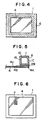
- FIGs 4 and 5 an area in which the plastic mask plate 4 is secured to the mask frame 1 may be protected from peeling by being taped with a protective tape 6.
- Figure 4 shows a top plan view of the plastic mask unit 100 with the protective tape 6 in place
- Figure 5 shows a sectional view of this.
- the placement of the protective tape 6 in Figures 4 and 5 may be made in the order of the bottom surface 4B for a length longer than the pipe width of the mask frame 1, an edge 4D of the plastic mask plate 4, an edge 2A of the adhesive 2, a side surface 1A of the mask frame 1, an upper surface 1B of the mask frame 1, an inner surface 1C of the mask frame 1, and the upper surface 4A of the plastic mask plate 4.
- the placement of the protective tape 6 may be made in the reverse order.
- the adhesion strength of the adhesive 2 is relatively insufficient, it is preferable to provide a rough finish to the surfaces of the mask frame 1 and the mask plate 4 to which adhesion is made, during the process of applying adhesives. It is also preferable to provide a large number of fine holes in the surface of the mask plate 4.
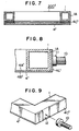
- the plastic mask unit After completing the placement of the protective tape in the above-mentioned manner, the plastic mask unit is subjected to irradiation by an excimer laser beam so that the plastic mask plate 4 thereof is formed with a plurality of slit-shaped through-holes 7 therein for serving as a print pattern for paste printing. Consequently, the fabrication procedure is ended and, as a result, there is fabricated one plastic mask unit 100' according to the present invention as shown in Figure 6, which is equivalent to the one shown in Figure 1.
- a plastic mask unit 200' shown in Figure 7 is fabricated in a manner similar to the plastic mask unit 100' shown in Figure 1, except for a process in which an edge 4C' of a plastic mask plate 4' of the plastic mask unit 200' is bent so as to be secured to an outer side 1A of a mask frame 1, in order to protect the plastic mask plate 4' and the mask frame 1 from peeling. More specifically, the edge 4C' of the plastic mask plate 4' is bent along the outer side 1A of the mask frame 1, while being outwardly subjected to a predetermined tension by the tension members 5 described hereinbefore, so that the mask frame 1 and the plastic mask plate 4' are firmly secured. In the above-mentioned bending process, the bending may be made at two opposite edges 4C' of the plastic mask plate 4', although it is preferable to bend all four edges 4C' of the plastic mask plate 4'.
- a plastic mask unit is supported by clamps in a paste printing machine during an operation.
- a clamp 10 shown in Figure 8 must be attached in a way so as not to damage any part of the edges 4C' of the plastic mask plate 4'. This is because registration of the plastic mask unit 200' with respect to a printing material becomes inaccurate due to abrasion of the edges 4C' of the plastic mask plate 4' if a holding part 11 of each clamp 10 holds the plastic mask unit 200' by pressing the edges 4C' of the plastic mask plate 4' as shown in Figure 8.
- the edges 4C' of the plastic mask plate 4' may be provided with a cut-out 12 as shown in Figure 9. In this way, the edges 4C' of the plastic mask plate 4' are not abraded by contact with the clamps 10 and, therefore, registration of the plastic mask unit 200' with respect to the printing material is not made inaccurate because of the clamps 10.
Landscapes
- Engineering & Computer Science (AREA)
- Manufacturing & Machinery (AREA)
- Microelectronics & Electronic Packaging (AREA)
- Physics & Mathematics (AREA)
- General Physics & Mathematics (AREA)
- Mechanical Engineering (AREA)
- Printing Plates And Materials Therefor (AREA)
- Manufacture Or Reproduction Of Printing Formes (AREA)
- Screen Printers (AREA)
- Manufacturing Of Printed Wiring (AREA)
- Inks, Pencil-Leads, Or Crayons (AREA)
Abstract
Description
- This invention relates to a mask unit for paste printing for forming patterns by use of an ink, an adhesive, solder paste, or a paste-like resin on a printing material, and more particularly to a plastic mask unit which has a long life and is capable of performing paste printing of a superior quality.
- This invention also relates to a method of fabricating the above-mentioned plastic mask unit.
- In the field of paste printing, several different types of conventional masks have been put in practice for forming printed patterns on a printing material by use of various pastes, such as, solder paste, an ink, an adhesive agent, and a paste resin (hereinafter referred to as the paste). An example of conventional printing masks for the paste printing is a mask known as a punch press mask which can be prepared by forming round through-holes in a metal sheet with a punch. Another example is a YAG laser mask which can be prepared by forming through-holes in a metal sheet with a YAG laser. Another example is an etching mask which can be prepared by forming through-holes in a metal sheet using a metal etching process. Still another example is an additive mask which can be prepared by forming through-holes in a metal plate formed by being plated around a pattern of through-holes.
- In addition to the above-mentioned metal masks, a mask made of a plastic sheet has been recently introduced which is disclosed in JP-A-7-81027. This plastic mask can be prepared by forming slit-shaped through-holes in a plastic sheet by excimer laser abrasion. As a result, the plastic mask becomes free from various known shortcomings, such as, for example, burr in the edges of the through-holes, deposition of dross in the through-holes, and so forth, that occur in the conventional metal masks. Also, such a plastic mask meets increasing demands for highly precise paste printing of a micro pattern with high quality, which arise from the recent trend whereby electronic appliances and parts are made smaller and smaller in size.
- JP-A-1-255536 discloses a screen printing plate which is produced by cutting a glass epoxy material in the size of a screen printing plate, drilling through-holes in a pattern figure in the screen material, thus manufacturing a screen plate, and fastening the screen plate to a screen frame. The glass epoxy material employed as a screen material is however disadvantageous as it lacks elastic properties.
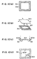
- In conventional masks, a metal sheet or a plastic sheet is secured to a mask frame with a mesh screen inserted in between. A fabrication procedure for these conventional masks is now explained with reference to Figures 10(a) - 10(h).
- In Figure 10(a),
reference numeral 301 denotes a mask frame to which a rectangular croos section aluminum pipe is commonly adopted. Such an aluminum mask frame is coated with a coating agent suitable for gluing aluminum so that a firstthin film 302 suitable for gluing aluminum is formed in a square frame on the edge of themask frame 301 as shown in Figure 10(a). A rubber adhesive diluted with a diluent is commonly applied to this coating material. A rough finish may be provided to the edge of themask frame 301 before the firstthin film 302 is formed thereon. - In a similar manner, a
mesh screen 303 is coated with a coating material suitable for gluing polyester, for example, so that a second thin film suitable for gluing polyester is formed in a square frame on themesh screen 303. For themesh screen 303, either a polyester mesh screen of about 180 to 225 mesh or a nylon mesh screen of about 180 to 225 mesh can be applied. - Next, a step of gluing the
polyester mesh screen 303 to themask frame 301 is illustrated in Figure 10(b). An example of an adhesive is an epoxy type adhesive which is suitable for gluing both the first thin film formed on themask frame 301 and the second thin film formed on thepolyester mesh screen 303. Such an epoxy adhesive is coated on either one or both of the first thin film formed on themask frame 301 and the second thin film formed on thepolyester mesh screen 303. After that, thepolyester mesh screen 303 is affixed to themask frame 301 with the application of a predetermined tension thereto in the directions as indicated by arrows in Figure 10(b). - As a result, the
mesh screen 303 is secured to themask frame 301 as shown in Figure 10(c). Since, in addition to extension caused by the predetermined tension, themesh screen 303 is prepared in a predetermined size larger than themask frame 301, there are overhanging edges 303a of the mesh screen relative to the periphery of themask frame 301 as shown in Figure 10(c). Accordingly, these overhanging edges 303a of themesh screen 303 are cut off so that themesh screen 303 becomes equal in size to themask frame 301 in the horizontal plain in the drawing. - Next, a step of drawing register marks for accurately registering the mesh screen relative to the mask plate is shown in Figure 10(d). A register mark 303b is drawn at the centers of all four sides of the
mesh screen 303 secured to themask frame 301. The register marks 303b are drawn softly and visibly using a sharp-pointed pencil on themesh screen 303 so that themask plate 304 can be accurately registered relative to themesh screen 303 in the following step. - The
mask plate 304 is then coated with a coating agent as shown in Figure 10(e). Thismask plate 304 includes a number of slit-shaped through-holes for serving as a print pattern for paste printing. The edge of the mask plate 104 is coated with a coating agent suitable for gluing themask plate 304. As a result, a thin film 304b suitable for gluing themask plate 304 is formed. Then, themask plate 304 is secured to themesh screen 303. In this event, a rubber type adhesive diluted with a diluent is usually applied to the coating agent. In addition, the edge frame of themesh screen 303 may be coated with another coating agent suitable for gluing polyester, for example, so that a polyester thin film suitable for gluing polyester can be formed on the edge frame of themesh screen 303. Moreover, a rough finish or a number of fine holes may be provided at the edge of themask plate 304 before the thin film 304b is formed thereon. - Next, the step of securing the
mask plate 304 to themesh screen 303 on themask frame 301 is shown in Figure 10(f). In this step, the position of themask plate 304 on themesh screen 303 is manually adjusted so that center holes 304c on each side of themask plate 304 and the register marks 303b of themesh screen 303 can be finely registered. Then, themask plate 304 is temporarily taped to themask frame 301 and themesh screen 303 to form an integrated unit. After that, this one unit of themask frame 301, themesh screen 303, and themask plate 304 is turned upside down and masking tape is placed over a relatively large area of themesh screen 303, leaving an area in the form of a square frame to be coated with adhesive, while the taped area is not coated with the adhesive. This masking tape must be in place before an epoxy type adhesive, for example, is coated onto the square frame of themesh screen 303. The masking tape is removed after the adhesive is cured on themesh screen 303. - The step of making an opening 303c is explained in Figure 10(g). The opening 303c is formed by cutting out the
mesh screen 303. The area cut must not be secured by themask plate 304 so that aportion 305 in which the adhesive is cured on themesh screen 303 can be left. After that, each glued portion is provided with guard tapes to prevent peeling-off so that themask frame 301 and themesh screen 303, themask plate 304 and themesh screen 303 are mutually secured. - In this way, the conventional mask unit for paste printing is fabricated. Consequently, the thus fabricated printing mask unit has a three-layer structure wherein the
mask frame 301 and themask plate 304 are secured with themesh screen 303 inserted in between, as shown in Figures 10(g) and 10(h). - However, there has been a problem in which registration of through-holes relative to the printing material becomes inaccurate in the case where a plastic sheet is applied to the mask plate during the above-mentioned fabrication procedure of the mask unit for paste printing. This is because of the tension, which is applied to the mesh screen secured to the mask frame, for holding the mask plate at a relatively high degree of flatness when the mask plate is secured to the mask frame. Accordingly, when a plastic sheet is used as the mask plate, this plastic mask plate may be overstretched by the above-mentioned tension and thereby registration of through-holes relative to the printing material may deteriorate.
- There has been another problem in the above-mentioned conventional mask unit for paste printing in which the life of the mask unit becomes relatively short. This is because two secured portions of the conventional mask unit, one between the mask frame and the mesh screen and the other between the mask plate and the mesh screen, are breakable and apt to be peeled off when the mask unit is subjected to washing for a number of times to protect the through-holes from being filled with paste material. In this case, if the secured portions are peeled off, the mask plate loses tension so that the position of the through-holes relative to the printing material is displaced, resulting in deterioration of print quality.
- Further, there has been another problem in the conventional mask unit for paste printing and its fabrication procedure. This is an increase in fabrication steps, such as, for example, the step of placing a masking tape on the mesh screen, the step of cutting off the mesh screen, and so forth.
- Further, there has been another problem in the conventional mask unit for paste printing and its fabrication procedure. This is the problem of displacement of the mask plate relative to the mask frame. This is because the steps for securing the elements are separated into one step for the mask frame and the mesh screen and another step for the mask plate and the mesh screen. The resultant displacement causes inaccurate registration of the through-holes of the mask plate relative to the printing material, leading to a deterioration of print quality. Moreover, owing to this problem, there has been another problem in which fine adjustment of the position of the mask plate is required during installation of the mask unit on a paste printing machine.
- Accordingly, an object of the present invention is to provide a novel plastic mask unit for paste printing which is superior in accurate registration of a print pattern thereof relative to a printing material and capable of performing paste printing with superior printing quality.
- Another object of the present invention is to provide a novel plastic mask unit for paste printing which has a relatively long life and is therefore capable of performing paste printing for a relatively large number of times.
- Another object of the present invention is to provide a novel plastic mask unit for paste printing which is fabricated in a relatively small number of fabrication steps.
- Another object of the present invention is to provide a novel plastic mask unit for paste printing which is installed in a relatively small number of installation steps on a paste printing machine.
- Another object of the present invention is to provide a method of fabricating the above-mentioned novel plastic mask unit for paste printing.
- The above objects of the present invention can be achieved by the plastic mask unit for paste printing according to
Claim 1 or 2 and the fabrication method according toClaim 4. - A mask unit for paste printing according to the present invention is a plastic mask unit which includes a mask frame and a mask plate including a plastic sheet formed with a plurality of slit-shaped through-holes therein for serving as a print pattern for paste printing, and wherein the mask plate is secured directly to the mask frame.
- In the above-mentioned plastic mask unit, the mask plate is secured directly to the mask frame with at least one adhesive.
- The above-mentioned adhesive includes three adhesive layers, a first adhesive layer which is suitable for adhering to the mask frame and placed on the mask frame side, a second adhesive layer which is suitable for adhering to the mask plate and placed on the mask plate side, and a third adhesive layer which is suitable for adhering to the first and second layers and placed between the first and second layers.
- Further, the above-mentioned mask frame is secured to a first adhesive thin film suitable for adhering the mask frame, the mask plate is secured to a second adhesive thin film suitable for adhering to the mask plate, and the mask frame and the mask plate are secured together by an adhesive suitable for adhering to the first and second adhesive thin films.
- Furthermore, the above-mentioned mask plate includes a plastic sheet which is formed with a plurality of slit-shaped through-holes for serving as a print pattern for paste printing by using an excimer laser.
- A method of fabricating a plastic mask unit, which includes a mask frame and a mask plate including a plastic sheet, for paste printing, according to the present invention, includes steps of securing the mask plate directly to the mask frame and then forming the mask plate with a plurality of slit-shaped through-holes for serving as a print pattern for paste printing.
- In the above-mentioned plastic mask unit fabrication method, the step of securing the mask plate directly to the mask frame including steps of coating a first adhesive, suitable for adhering to the mask frame, on the surface of the mask frame, coating a second adhesive, suitable for adhering to the mask plate, on the surface of the mask plate, and then securing the mask plate directly to the mask frame by a third adhesive suitable for adhering to the first and second adhesives.
- Further, the above-mentioned step of securing the mask plate directly to the mask frame including steps of securing the mask frame to a first adhesive thin film suitable for adhering to the mask frame, securing the mask plate to a second adhesive thin film suitable for adhering to the mask plate, and then securing the mask plate directly to the mask frame with an adhesive suitable for adhering to the first and second adhesive thin films.
- Furthermore, in the above-mentioned plastic mask unit fabrication method, the step of forming the mask is carried out by using an excimer laser.
- As a feature of a plastic mask unit for paste printing according to the present invention, the plastic mask unit for paste printing can be made superior in accurate registration of slit-shaped through-holes thereof relative to a printing material and therefore capable of performing the paste printing with superior printing quality. This is due to an arrangement in which a plastic mask plate including a plurality of slit-shaped through-holes therein is secured directly to a mask frame. Such an arrangement subsequently provides an effect whereby the plastic mask plate can be kept in a plane shape by its own elasticity even with less tension provided from the outside, in comparison with the case of using a mesh screen. Accordingly, such tension provided from the outside to the plastic mask plate can be reduced and, subsequently, the amount of extension of the plastic mask plate can be reduced. Thereby the plastic mask unit can improve the printing quality in the manner mentioned above.
- Moreover, the plastic mask plate can be set in relatively close contact relative to the printing material, with the tension provided from the outside being reduced. Thereby, the plastic mask unit can perform fine paste printing in which less blurs occur.
- As another feature of the above-mentioned plastic mask unit for paste printing according to the present invention, the plastic mask unit is free from displacement of the slit-shaped through-holes relative to the printing material. Accordingly, the plastic mask unit for paste printing according to the present invention provides superior accuracy in the registration of slit-shaped through-holes relative to the printing material and, subsequently, becomes capable of performing paste printing with superior printing quality.
- This is due to an arrangement in which the number of mating faces of structural elements of the plastic mask unit is reduced so that the conventional mesh screen is eliminated and only a plastic mask plate and a mask frame are required. Accordingly, damage to the plastic mask unit due to peeling of the mating faces is rarely caused even when the plastic mask unit is subjected to a relatively large number of washes for protecting the through-holes from being filled with paste material or the like.
- More specifically, in the plastic mask unit according to the present invention, the mating faces of the plastic mask plate and the mask frame can be made in a relatively large size, approximately 40 mm in width, for example, while those of the conventional mask unit can be made approximately 10 mm to 15 mm in width, for example. The capability of making such large-sized mating faces also supports the above-mentioned explanation that damage to the plastic mask unit due to peeling of the mating faces is rarely caused. Accordingly, the plastic mask unit according to the present invention becomes capable of performing paste printing with superior printing quality. Moreover, the plastic mask unit according to the present invention can be used for a relatively large number of times over a relatively long life span without damage from peeling of the mating faces.
- As a feature of a method of fabricating the plastic mask unit for paste printing according to the present invention, a method of fabricating the plastic mask unit for paste printing can reduce the number of fabrication steps in comparison with the number of fabrication steps for the conventional mask unit. This is due to an arrangement whereby a mask plate is secured directly to a mask frame and a mesh screen is eliminated from the structural elements of the conventional mask unit. Accordingly, various fabrication steps, such as, for example, the step of securing the mesh screen to the mask frame, the step of securing the mask plate to the mesh screen, the step of cutting out a middle portion of the mesh screen, the step of securing a protective tape on mating portions of the mesh screen and the mask plate, and so forth, are eliminated. Moreover, the above-mentioned method of fabricating the plastic mask unit for paste printing can reduce the fabrication cost in view of not only fabrication hours but also elimination of parts.
- Specifically, in the above-mentioned plastic mask unit fabricating method, there are preferable methods for securing the plastic mask plate, formed with a plurality of slit-shaped through-holes therein for serving as a print pattern for paste printing, directly to the mask frame. As an example, it is preferable to use an adhesive which is suitable for adhering to both of the materials of the plastic mask plate and the mask frame. As another example, it is also preferable to coat an adhesive suitable for adhering to materials of the mask frame on the mask frame side, to coat an adhesive suitable for adhering to materials of the plastic mask frame on the plastic mask plate side, and, then, to secure the mask frame and the plastic mask plate by an adhesive suitable for adhering to both of the materials of the plastic mask plate and the mask frame. As another example, it is also preferable to form a thin film suitable for adhering to the mask frame on a face to which the plastic mask plate is secured, to form a thin film suitable for adhering to the plastic mask plate on a face to which the mask frame is secured, and, then, to secure the mask frame and the plastic mask plate by an adhesive suitable for adhering to both of the thin films.
- Moreover, in the above-mentioned preferable methods for securing the plastic mask plate directly to the mask frame, the mask frame and the plastic mask plate can be tightly secured by providing a rough finish on the surfaces of either or both of the mask frame and the plastic mask plate, or by forming a relatively large number of fine holes in the surface of the plastic mask plate.
- As another feature of the method of fabricating the plastic mask unit for paste printing according to the present invention, the method of fabricating the plastic mask unit for paste printing can eliminate displacement of a print pattern including a plurality of slit-shaped through-holes relative to the printing material. Accordingly, this method of fabricating the plastic mask unit can provide a plastic mask unit which is capable of performing paste printing with superior quality. This is due to an arrangement whereby a plastic mask unit is subjected to a fabrication step of forming a plastic mask plate with a plurality of slit-shaped through-holes for serving as a print pattern for paste printing after the plastic mask unit has been fabricated in a semifinished form by securing the plastic mask plate directly to the mask frame without the forming process. Since the print pattern for paste printing is formed directly on the plastic mask unit, displacement is minimized in comparison with the case of the conventional mask unit for which the print pattern is formed on the mask plate before the mask plate is secured to the mask frame. Accordingly, the plastic mask unit fabricated by the above-mentioned method can perform fine paste printing with superior quality. Moreover, in such plastic mask unit fabricated by the above-mentioned method, steps of adjusting the position of the plastic mask unit in the paste printing machine can be eliminated.
- Specifically, in the above-mentioned plastic mask unit fabricating method, there are preferable methods for securing the plastic mask plate, formed with no print pattern, directly to the mask frame. As an example, it is preferable to use an adhesive which is suitable for adhering to both the materials of the plastic mask plate and the mask frame. As another example, it is also preferable to coat an adhesive suitable for adhering to materials of the mask frame onto the mask frame side, to coat an adhesive suitable for adhering to materials of the plastic mask frame onto the plastic mask plate side, and, then, to secure the mask frame and the plastic mask plate by an adhesive suitable for adhering to both the materials of the plastic mask plate and the mask frame. As another example, it is also preferable to form a thin film suitable for adhering to the mask frame on a face to which the plastic mask plate is secured, to form a thin film suitable for adhering to the plastic mask plate on a face to which the mask frame is secured, and, then, to secure the mask frame and the plastic mask plate by an adhesive suitable for adhering to both the thin films.
- Moreover, in the above-mentioned preferable methods for securing the plastic mask plate directly to the mask frame, the mask frame and the plastic mask plate can be tightly secured by providing a rough finish on the surfaces of either or both of the mask frame and the plastic mask plate, or by forming a relatively large number of fine holes in the surface of the plastic mask plate.
- Furthermore, in the above-mentioned plastic mask unit fabricating method, it is preferable to form the plastic mask plate with a plurality of slit-shaped through-holes therein for serving as a print pattern for paste printing by excimer laser abrasion.
- Other objects, features, and advantages of the present invention will become apparent from the following detailed description when read in conjunction with the accompanying drawings.
- A more complete appreciation of the present invention and many of the attendant advantages thereof will be readily obtained as the same becomes better understood by reference to the following detailed description when considered in connection with the accompanying drawings, wherein:
- Figure 1 is a sectional view of an example of a plastic mask unit for paste printing according to the present invention;
- Figure 2 is an exploded sectional view of the plastic mask unit shown in Figure 1;
- Figure 3 is a sectional view of the plastic mask unit shown in Figure 1 for showing how a mask plate is secured to a mask frame;
- Figure 4 is a top plan view of the plastic mask unit shown in Figure 1 for showing the plastic mask unit taped with a protective tape for protecting peeling at an area where the mask plate is secured to a mask frame;
- Figure 5 is a sectional view of a part of the plastic mask unit shown in Figure 1 for showing a method for placing the protective tape;
- Figure 6 is a top plan view of the plastic mask unit shown in Figure 1 including through-holes therein for serving as a print pattern for paste printing;
- Figure 7 is a sectional view of another example of a plastic mask unit for paste printing according to the present invention;
- Figure 8 is a sectional view of a part of the plastic mask unit shown in Figure 7 for showing how the plastic mask unit is supported by clamps;
- Figure 9 is a perspective view of a part of another example of a plastic mask unit, including a clamped, for paste printing according to the present invention;
- Figures 10(a)-19(h) are illustrations for showing a conventional fabrication procedure for a conventional mask unit for paste printing.
-
- In describing preferred embodiments of the present invention illustrated in the drawings, specific terminology is employed for the sake of clarity. However, the present invention is not intended to be limited to the specific terminology so selected and it is to be understood that each specific element includes all technical equivalents which operate in a similar manner.
- Referring now to the drawings, wherein like reference numerals designate identical or corresponding parts throughout the several views, and more particularly to Figure 1 thereof, there is illustrated a sectional view of an example of a novel plastic mask unit 100' for paste printing including a mask frame 1 and a mask plate 4', made of a plastic sheet including a plurality of slit-shaped through-holes therein for serving as a print pattern for paste printing, for performing as a print mask, and wherein such a plastic mask plate 4' is secured directly to the mask frame 1. In this plastic mask unit 100', a thin film of an adhesive 2 is formed between the mask frame 1 and the plastic mask plate 4', by which the plastic mask plate 4' is secured directly to the mask frame 1 as shown in Figure 1. Such an adhesive 2 has a three-layer structure including a first adhesive 21 adhering to a mask frame 1 side, a second adhesive 22 adhering to a plastic mask plate 4' side, and a third adhesive 23 securing the first adhesive 21 to the
second adhesive 22. Accordingly, the mask frame 1 is secured to anupper surface 4A' of the plastic mask plate 4'. In addition,reference numeral 4B' in Figure 1 denotes the bottom surface of the plastic mask plate 4'. - Next, processes for coating adhesives onto the mask frame 1 and a
plastic mask plate 4 during fabrication of theplastic mask unit 100, which is expected to become the above-mentioned plastic mask unit 100', are explained with reference to Figure 2. In this case, theplastic mask unit 100 represents a semifinished form of the plastic mask unit 100', since theplastic mask plate 4 is in a form expected to be formed with a plurality of through-holes therein for serving as a print pattern for paste printing. Accordingly, theplastic mask unit 100 becomes the plastic mask 100' when theplastic mask plate 4 is formed with a plurality of through-holes therein for serving as a print pattern for paste printing. - In the embodiment shown in Figure 2, a rubber type adhesive is diluted with methylethylketone and coated onto a portion of the aluminum square pipe mask frame 1, on which the
plastic mask plate 4 is placed, so as to form a thin film of the first adhesive 21 after the adhesive has dried. Also, a rubber type adhesive is diluted with methylethylketone and coated onto a portion of theplastic mask plate 4, on which the mask frame 1 is placed, so- as to form a thin film of the second adhesive 22 after the adhesive has dried. Further, an epoxy type adhesive as the third adhesive is coated onto the surface of the thin film made of the first adhesive 21 secured to the mask frame 1 and the surface of the thin film made of the second adhesive 22 secured to theplastic mask plate 4. - Although, in the above-mentioned embodiment, the rubber type adhesive is used as an adhesive suitable for adhering to the aluminum square pipe mask frame 1 and the
plastic mask plate 4 and the epoxy type adhesive is used as an adhesive suitable for adhering to the thin films made of the rubber type adhesive, other types of adhesives suitable for adhering the mask frame, the plastic mask plate, and thin films made of these adhesives, respectively, may be used. - Next, a process of securing the
plastic mask plate 4 to the mask frame 1 is explained with reference to Figure 3. As shown in Figure 3, each of the four sides of theplastic mask plate 4 is equally subjected to a predetermined tension along the whole length of each side bytension members 5 in the directions indicated by the arrows in Figure 3 and in the forward and reverse directions along an axis perpendicular to the drawing. This application of the predetermined tension to the sides of theplastic mask plate 4 is carried out while theplastic mask plate 4 is being placed and secured to the mask frame 1. After theplastic mask plate 4 is secured to the mask frame 1, the adhesive 2 is subsequently formed into a film between these two elements. Only after the adhesive 2 is cured, thetension members 5 are removed from theplastic mask plate 4. Since, in addition to an extension made by thetension members 5, theplastic mask 4 is prepared in a predetermined size larger than that of the mask frame 1, there are overhangingedges 4C of theplastic mask plate 4 relative to the periphery of the mask frame 1. Accordingly, these excess edge sides 4C of theplastic mask plate 4 are cut off so that theplastic mask plate 4 becomes equal to the mask frame 1 in size in the horizontal plane on the drawing. - As shown in Figures 4 and 5, an area in which the
plastic mask plate 4 is secured to the mask frame 1 may be protected from peeling by being taped with aprotective tape 6. Figure 4 shows a top plan view of theplastic mask unit 100 with theprotective tape 6 in place, and Figure 5 shows a sectional view of this. The placement of theprotective tape 6 in Figures 4 and 5 may be made in the order of thebottom surface 4B for a length longer than the pipe width of the mask frame 1, an edge 4D of theplastic mask plate 4, an edge 2A of the adhesive 2, a side surface 1A of the mask frame 1, an upper surface 1B of the mask frame 1, an inner surface 1C of the mask frame 1, and theupper surface 4A of theplastic mask plate 4. Of course, the placement of theprotective tape 6 may be made in the reverse order. - In the case where the adhesion strength of the adhesive 2 is relatively insufficient, it is preferable to provide a rough finish to the surfaces of the mask frame 1 and the
mask plate 4 to which adhesion is made, during the process of applying adhesives. It is also preferable to provide a large number of fine holes in the surface of themask plate 4. - After completing the placement of the protective tape in the above-mentioned manner, the plastic mask unit is subjected to irradiation by an excimer laser beam so that the
plastic mask plate 4 thereof is formed with a plurality of slit-shaped through-holes 7 therein for serving as a print pattern for paste printing. Consequently, the fabrication procedure is ended and, as a result, there is fabricated one plastic mask unit 100' according to the present invention as shown in Figure 6, which is equivalent to the one shown in Figure 1. - Next, another example of a plastic mask unit according to the present invention is explained with reference to Figures 7-9. A plastic mask unit 200' shown in Figure 7 is fabricated in a manner similar to the plastic mask unit 100' shown in Figure 1, except for a process in which an
edge 4C' of a plastic mask plate 4' of the plastic mask unit 200' is bent so as to be secured to an outer side 1A of a mask frame 1, in order to protect the plastic mask plate 4' and the mask frame 1 from peeling. More specifically, theedge 4C' of the plastic mask plate 4' is bent along the outer side 1A of the mask frame 1, while being outwardly subjected to a predetermined tension by thetension members 5 described hereinbefore, so that the mask frame 1 and the plastic mask plate 4' are firmly secured. In the above-mentioned bending process, the bending may be made at twoopposite edges 4C' of the plastic mask plate 4', although it is preferable to bend all fouredges 4C' of the plastic mask plate 4'. - In general, a plastic mask unit is supported by clamps in a paste printing machine during an operation. When the above-mentioned plastic mask unit 200' is used in the paste printing machine, a
clamp 10 shown in Figure 8 must be attached in a way so as not to damage any part of theedges 4C' of the plastic mask plate 4'. This is because registration of the plastic mask unit 200' with respect to a printing material becomes inaccurate due to abrasion of theedges 4C' of the plastic mask plate 4' if a holding part 11 of eachclamp 10 holds the plastic mask unit 200' by pressing theedges 4C' of the plastic mask plate 4' as shown in Figure 8. In order to avoid this problem, theedges 4C' of the plastic mask plate 4' may be provided with a cut-out 12 as shown in Figure 9. In this way, theedges 4C' of the plastic mask plate 4' are not abraded by contact with theclamps 10 and, therefore, registration of the plastic mask unit 200' with respect to the printing material is not made inaccurate because of theclamps 10. - Obviously, numerous additional modifications and variations of the present invention are possible in light of the above teachings. It is therefore to be understood that within the scope of the appended claims, the present invention may be practiced otherwise than as specifically described herein.
Claims (7)
- A plastic mask unit for paste printing, comprising:a mask frame; anda mask plate comprising a plastic sheet having elastic properties formed with a plurality of slit-shaped through-holes therein for serving as a print pattern for paste printing, and secured directly to said mask frame with an adhesive comprising three adhesive layers, a first adhesive layer which is suitable for adhering to said mask frame and placed on a mask frame side, a second adhesive layer which is suitable for adhering to said mask plate and placed on a mask plate side, and a third adhesive layer which is suitable for adhering to said first and second layers and placed between said first and second layers.
- A plastic mask unit for paste printing, comprising:a mask frame; anda mask plate comprising a plastic sheet having elastic properties formed with a plurality of slit-shaped through-holes therein for serving as a print pattern for paste printing, and secured directly to said mask frame, wherein said mask frame is secured to a first adhesive thin film suitable for adhering to said mask frame, said mask plate is secured to a second adhesive thin film suitable for adhering to said mask plate, and said mask frame and said mask plate are secured together by an adhesive suitable for adhering to said first and second adhesive thin films.
- The plastic mask unit according to any one of claims 1 or 2, wherein said mask plate comprises a plastic sheet which is formed with a plurality of slit-shaped through-holes for serving as a print pattern for paste printing using an excimer laser.
- A method of fabricating a plastic mask for paste printing according to claim 1 or 2 which comprises the steps of:first securing said mask plate comprising a plastic sheet having elastic properties directly to said mask frame;and then forming said mask plate with a plurality of slit-shaped through-holes for serving as a print pattern for paste printing.
- The method of claim 4 wherein said step of securing said mask plate directly to said mask frame comprises the steps of:coating a first adhesive, suitable for adhering to said mask frame, onto a surface of said mask frame;coating a second adhesive, suitable for adhering to said mask plate, onto a surface of said mask plate; andsecuring said mask plate directly to said mask frame by a third adhesive suitable for adhering to said first and second adhesives.
- The method of claim 4 wherein said step of securing said mask plate directly to said mask frame comprises the steps of:securing said mask frame to a first adhesive thin film suitable for adhering to said mask frame;securing said mask plate to a second adhesive thin film suitable for adhering to said mask plate; andsecuring said mask plate directly to said mask frame with an adhesive suitable for adhering to said first and second adhesive thin films.
- The method of any one of claims 4-6, wherein said step of forming said mask is carried out by using an excimer laser.
Applications Claiming Priority (3)
| Application Number | Priority Date | Filing Date | Title |
|---|---|---|---|
| JP333185/95 | 1995-12-21 | ||
| JP33318595 | 1995-12-21 | ||
| JP33318595 | 1995-12-21 |
Publications (2)
| Publication Number | Publication Date |
|---|---|
| EP0780225A1 EP0780225A1 (en) | 1997-06-25 |
| EP0780225B1 true EP0780225B1 (en) | 2003-05-02 |
Family
ID=18263259
Family Applications (1)
| Application Number | Title | Priority Date | Filing Date |
|---|---|---|---|
| EP96120634A Expired - Lifetime EP0780225B1 (en) | 1995-12-21 | 1996-12-20 | Plastic mask unit for paste printing and method of fabricating such plastic mask unit |
Country Status (6)
| Country | Link |
|---|---|
| US (1) | US6286424B1 (en) |
| EP (1) | EP0780225B1 (en) |
| KR (1) | KR100227917B1 (en) |
| AT (1) | ATE238908T1 (en) |
| DE (1) | DE69627794D1 (en) |
| TW (1) | TW342365B (en) |
Families Citing this family (5)
| Publication number | Priority date | Publication date | Assignee | Title |
|---|---|---|---|---|
| US7866261B2 (en) * | 2007-05-23 | 2011-01-11 | Rapid Screen Products Corporation | Metal stencil foil attachment to screen mesh |
| CN101318401B (en) * | 2007-06-08 | 2010-12-29 | 富葵精密组件(深圳)有限公司 | Screen printing plate and manufacturing method thereof |
| CN104451538B (en) * | 2014-12-30 | 2017-06-06 | 合肥鑫晟光电科技有限公司 | Mask plate and preparation method thereof |
| CN114055916B (en) * | 2021-11-12 | 2022-05-03 | 广东方舟智造科技有限公司 | Shading layer printing forming equipment and method for keyboard circuit film |
| DE102022203815A1 (en) | 2022-04-19 | 2023-10-19 | Robert Bosch Gesellschaft mit beschränkter Haftung | Method for coating a distribution plate for an electrochemical cell |
Family Cites Families (35)
| Publication number | Priority date | Publication date | Assignee | Title |
|---|---|---|---|---|
| US3435758A (en) * | 1966-03-02 | 1969-04-01 | Dymo Industries Inc | Stencil and method of making the same |
| US3934503A (en) * | 1967-06-26 | 1976-01-27 | Iit Research Institute | Stencil screens |
| US3668028A (en) * | 1970-06-10 | 1972-06-06 | Du Pont | Method of making printing masks with high energy beams |
| CA1049312A (en) * | 1974-01-17 | 1979-02-27 | John O.H. Peterson | Presensitized printing plate with in-situ, laser imageable mask |
| DE3216466A1 (en) * | 1982-05-03 | 1983-11-03 | Kissel + Wolf GmbH, 6908 Wiesloch | Screen adhesive |
| US4702783A (en) * | 1982-10-25 | 1987-10-27 | Uncommon Conglomerates, Inc. | Adhesive technology |
| GB2162015A (en) * | 1984-05-23 | 1986-01-22 | Brinmiln Ltd | Method of screen printing |
| JPS61229595A (en) * | 1985-04-04 | 1986-10-13 | Ricoh Co Ltd | Direct plate making material for screen printing |
| US4802945A (en) * | 1986-10-09 | 1989-02-07 | Hughes Aircraft Company | Via filling of green ceramic tape |
| US4791006A (en) * | 1987-06-04 | 1988-12-13 | Avx Corporation | High accuracy variable thickness laydown method for electronic components |
| JPH0792512B2 (en) * | 1987-11-02 | 1995-10-09 | 株式会社日立製作所 | Fuel assembly and reactor core |
| JPH01255536A (en) * | 1988-04-06 | 1989-10-12 | Oki Electric Ind Co Ltd | Manufacture of screen printing plate |
| US5054391A (en) * | 1989-05-12 | 1991-10-08 | Riso Kagaku Corporation | Thermal stencil sheet assembly with stencil sheet temporarily detachable from frame |
| US5003870A (en) * | 1989-08-21 | 1991-04-02 | Hughes Aircraft Company | Antistretch screen printing arrangement |
| US5058499A (en) * | 1990-05-31 | 1991-10-22 | Xpres Corporation | Imparting an image on a substrate |
| WO1992008616A1 (en) * | 1990-11-19 | 1992-05-29 | Prss-Maschinen Ag | Solder or conductive paste printing device |
| ATE176416T1 (en) * | 1990-11-21 | 1999-02-15 | Canon Kk | LASER PROCESSING DEVICE |
| US5314709A (en) * | 1991-03-20 | 1994-05-24 | International Business Machines Corporation | Unzippable polymer mask for screening operations |
| JP3086066B2 (en) * | 1991-10-29 | 2000-09-11 | 富士通株式会社 | Cream solder printing method and electronic component soldering method |
| JP2582728Y2 (en) * | 1992-01-20 | 1998-10-08 | ブラザー工業株式会社 | Heat-sensitive stencil paper |
| US5359928A (en) * | 1992-03-12 | 1994-11-01 | Amtx, Inc. | Method for preparing and using a screen printing stencil having raised edges |
| US5703631A (en) * | 1992-05-05 | 1997-12-30 | Compaq Computer Corporation | Method of forming an orifice array for a high density ink jet printhead |
| JP3216920B2 (en) * | 1992-10-16 | 2001-10-09 | 理想科学工業株式会社 | Stencil printing method and stencil printing apparatus using laser |
| US5294567A (en) * | 1993-01-08 | 1994-03-15 | E. I. Du Pont De Nemours And Company | Method for forming via holes in multilayer circuits |
| US5460921A (en) * | 1993-09-08 | 1995-10-24 | International Business Machines Corporation | High density pattern template: materials and processes for the application of conductive pastes |
| JP3279761B2 (en) * | 1993-09-16 | 2002-04-30 | リコーマイクロエレクトロニクス株式会社 | Cream solder printing mask and printing method using the same |
| CN1044762C (en) * | 1993-09-22 | 1999-08-18 | 松下电器产业株式会社 | Printed circuit board and method of manufacturing the same |
| US5373627A (en) * | 1993-11-23 | 1994-12-20 | Grebe; Kurt R. | Method of forming multi-chip module with high density interconnections |
| FR2722138B1 (en) * | 1994-07-07 | 1996-09-20 | Bourrieres Francis | SCREEN PRINTING STENCIL AND METHOD FOR PRODUCING THE SAME |
| JP3587884B2 (en) * | 1994-07-21 | 2004-11-10 | 富士通株式会社 | Method for manufacturing multilayer circuit board |
| TW289901B (en) * | 1994-12-28 | 1996-11-01 | Ricoh Microelectronics Kk | |
| US5728244A (en) * | 1995-05-26 | 1998-03-17 | Ngk Insulators, Ltd. | Process for production of ceramic member having fine throughholes |
| US5669970A (en) * | 1995-06-02 | 1997-09-23 | Mpm Corporation | Stencil apparatus for applying solder paste |
| US5588359A (en) * | 1995-06-09 | 1996-12-31 | Micron Display Technology, Inc. | Method for forming a screen for screen printing a pattern of small closely spaced features onto a substrate |
| JPH09283904A (en) * | 1996-04-18 | 1997-10-31 | Matsushita Electric Ind Co Ltd | Creation method for recognition mark in resin screen mask |
-
1996
- 1996-12-16 TW TW085115521A patent/TW342365B/en not_active IP Right Cessation
- 1996-12-20 US US08/770,256 patent/US6286424B1/en not_active Expired - Fee Related
- 1996-12-20 DE DE69627794T patent/DE69627794D1/en not_active Expired - Lifetime
- 1996-12-20 EP EP96120634A patent/EP0780225B1/en not_active Expired - Lifetime
- 1996-12-20 AT AT96120634T patent/ATE238908T1/en not_active IP Right Cessation
- 1996-12-21 KR KR1019960069489A patent/KR100227917B1/en not_active IP Right Cessation
Also Published As
| Publication number | Publication date |
|---|---|
| TW342365B (en) | 1998-10-11 |
| US6286424B1 (en) | 2001-09-11 |
| KR100227917B1 (en) | 1999-11-01 |
| KR970048990A (en) | 1997-07-29 |
| DE69627794D1 (en) | 2003-06-05 |
| EP0780225A1 (en) | 1997-06-25 |
| ATE238908T1 (en) | 2003-05-15 |
Similar Documents
| Publication | Publication Date | Title |
|---|---|---|
| US5403684A (en) | PCB tooling apparatus and method for forming patterns in registration on both sides of a substrate | |
| US6544371B2 (en) | Method of using a transfer tape | |
| EP1579024B1 (en) | Flexible frame for mounting a deposition mask | |
| EP2998792B1 (en) | A pellicle frame and a pellicle | |
| EP0780225B1 (en) | Plastic mask unit for paste printing and method of fabricating such plastic mask unit | |
| US4462873A (en) | Method of fixedly arranging an array of electroformed letters or the like on an article | |
| US6982478B2 (en) | Semiconductor device and method of fabricating the same | |
| JP3003123B2 (en) | screen | |
| US6636334B2 (en) | Semiconductor device having high-density packaging thereof | |
| JPH04342196A (en) | Electronic component mounting palette | |
| KR0133994B1 (en) | Process for production of electroformed patterns | |
| JPH09232720A (en) | Printing mask and manufacture thereof | |
| JPH0745241B2 (en) | Combination mask manufacturing method and combination mask | |
| US6146698A (en) | Process for simultaneously wetting a plurality of electrical contact areas with a liquid | |
| US20020182370A1 (en) | Semiconductor packaging part and method producing the same | |
| JP3491489B2 (en) | Tab tape and manufacturing method thereof | |
| EP1024022A1 (en) | Plate for screen printing and method for manufacturing the same | |
| JP3141665B2 (en) | Printing plate manufacturing method | |
| JP3108865U (en) | Photomask for exposure | |
| JP2659335B2 (en) | Manufacturing method of electrodeposited image | |
| JPH038390A (en) | Manufacture of substrate for mounting electronic component | |
| JPH07302955A (en) | Double-sided flexible printed board | |
| KR910001141Y1 (en) | Printed circuit board for magnetic head | |
| JP3738499B2 (en) | Application method of conductive adhesive | |
| JPS61107789A (en) | Flexible printed circuit board and manufacture thereof |
Legal Events
| Date | Code | Title | Description |
|---|---|---|---|
| PUAI | Public reference made under article 153(3) epc to a published international application that has entered the european phase |
Free format text: ORIGINAL CODE: 0009012 |
|
| 17P | Request for examination filed |
Effective date: 19961220 |
|
| AK | Designated contracting states |
Kind code of ref document: A1 Designated state(s): AT BE CH DE DK ES FI FR GB GR IE IT LI LU MC NL PT SE |
|
| 17Q | First examination report despatched |
Effective date: 19980709 |
|
| GRAG | Despatch of communication of intention to grant |
Free format text: ORIGINAL CODE: EPIDOS AGRA |
|
| GRAG | Despatch of communication of intention to grant |
Free format text: ORIGINAL CODE: EPIDOS AGRA |
|
| GRAH | Despatch of communication of intention to grant a patent |
Free format text: ORIGINAL CODE: EPIDOS IGRA |
|
| GRAH | Despatch of communication of intention to grant a patent |
Free format text: ORIGINAL CODE: EPIDOS IGRA |
|
| GRAA | (expected) grant |
Free format text: ORIGINAL CODE: 0009210 |
|
| AK | Designated contracting states |
Designated state(s): AT BE CH DE DK ES FI FR GB GR IE IT LI LU MC NL PT SE |
|
| PG25 | Lapsed in a contracting state [announced via postgrant information from national office to epo] |
Ref country code: NL Free format text: LAPSE BECAUSE OF FAILURE TO SUBMIT A TRANSLATION OF THE DESCRIPTION OR TO PAY THE FEE WITHIN THE PRESCRIBED TIME-LIMIT Effective date: 20030502 Ref country code: LI Free format text: LAPSE BECAUSE OF FAILURE TO SUBMIT A TRANSLATION OF THE DESCRIPTION OR TO PAY THE FEE WITHIN THE PRESCRIBED TIME-LIMIT Effective date: 20030502 Ref country code: IT Free format text: LAPSE BECAUSE OF FAILURE TO SUBMIT A TRANSLATION OF THE DESCRIPTION OR TO PAY THE FEE WITHIN THE PRESCRIBED TIME-LIMIT;WARNING: LAPSES OF ITALIAN PATENTS WITH EFFECTIVE DATE BEFORE 2007 MAY HAVE OCCURRED AT ANY TIME BEFORE 2007. THE CORRECT EFFECTIVE DATE MAY BE DIFFERENT FROM THE ONE RECORDED. Effective date: 20030502 Ref country code: FR Free format text: LAPSE BECAUSE OF FAILURE TO SUBMIT A TRANSLATION OF THE DESCRIPTION OR TO PAY THE FEE WITHIN THE PRESCRIBED TIME-LIMIT Effective date: 20030502 Ref country code: FI Free format text: LAPSE BECAUSE OF FAILURE TO SUBMIT A TRANSLATION OF THE DESCRIPTION OR TO PAY THE FEE WITHIN THE PRESCRIBED TIME-LIMIT Effective date: 20030502 Ref country code: CH Free format text: LAPSE BECAUSE OF FAILURE TO SUBMIT A TRANSLATION OF THE DESCRIPTION OR TO PAY THE FEE WITHIN THE PRESCRIBED TIME-LIMIT Effective date: 20030502 Ref country code: BE Free format text: LAPSE BECAUSE OF FAILURE TO SUBMIT A TRANSLATION OF THE DESCRIPTION OR TO PAY THE FEE WITHIN THE PRESCRIBED TIME-LIMIT Effective date: 20030502 Ref country code: AT Free format text: LAPSE BECAUSE OF FAILURE TO SUBMIT A TRANSLATION OF THE DESCRIPTION OR TO PAY THE FEE WITHIN THE PRESCRIBED TIME-LIMIT Effective date: 20030502 |
|
| REG | Reference to a national code |
Ref country code: GB Ref legal event code: FG4D |
|
| REG | Reference to a national code |
Ref country code: CH Ref legal event code: EP |
|
| REF | Corresponds to: |
Ref document number: 69627794 Country of ref document: DE Date of ref document: 20030605 Kind code of ref document: P |
|
| REG | Reference to a national code |
Ref country code: IE Ref legal event code: FG4D |
|
| PG25 | Lapsed in a contracting state [announced via postgrant information from national office to epo] |
Ref country code: SE Free format text: LAPSE BECAUSE OF FAILURE TO SUBMIT A TRANSLATION OF THE DESCRIPTION OR TO PAY THE FEE WITHIN THE PRESCRIBED TIME-LIMIT Effective date: 20030802 Ref country code: GR Free format text: LAPSE BECAUSE OF FAILURE TO SUBMIT A TRANSLATION OF THE DESCRIPTION OR TO PAY THE FEE WITHIN THE PRESCRIBED TIME-LIMIT Effective date: 20030802 Ref country code: DK Free format text: LAPSE BECAUSE OF FAILURE TO SUBMIT A TRANSLATION OF THE DESCRIPTION OR TO PAY THE FEE WITHIN THE PRESCRIBED TIME-LIMIT Effective date: 20030802 |
|
| PG25 | Lapsed in a contracting state [announced via postgrant information from national office to epo] |
Ref country code: PT Free format text: LAPSE BECAUSE OF FAILURE TO SUBMIT A TRANSLATION OF THE DESCRIPTION OR TO PAY THE FEE WITHIN THE PRESCRIBED TIME-LIMIT Effective date: 20030804 |
|
| PG25 | Lapsed in a contracting state [announced via postgrant information from national office to epo] |
Ref country code: DE Free format text: LAPSE BECAUSE OF FAILURE TO SUBMIT A TRANSLATION OF THE DESCRIPTION OR TO PAY THE FEE WITHIN THE PRESCRIBED TIME-LIMIT Effective date: 20030805 |
|
| PG25 | Lapsed in a contracting state [announced via postgrant information from national office to epo] |
Ref country code: ES Free format text: LAPSE BECAUSE OF FAILURE TO SUBMIT A TRANSLATION OF THE DESCRIPTION OR TO PAY THE FEE WITHIN THE PRESCRIBED TIME-LIMIT Effective date: 20030813 |
|
| NLV1 | Nl: lapsed or annulled due to failure to fulfill the requirements of art. 29p and 29m of the patents act | ||
| REG | Reference to a national code |
Ref country code: CH Ref legal event code: PL |
|
| PG25 | Lapsed in a contracting state [announced via postgrant information from national office to epo] |
Ref country code: LU Free format text: LAPSE BECAUSE OF NON-PAYMENT OF DUE FEES Effective date: 20031220 Ref country code: GB Free format text: LAPSE BECAUSE OF NON-PAYMENT OF DUE FEES Effective date: 20031220 |
|
| PG25 | Lapsed in a contracting state [announced via postgrant information from national office to epo] |
Ref country code: IE Free format text: LAPSE BECAUSE OF NON-PAYMENT OF DUE FEES Effective date: 20031222 |
|
| PG25 | Lapsed in a contracting state [announced via postgrant information from national office to epo] |
Ref country code: MC Free format text: LAPSE BECAUSE OF NON-PAYMENT OF DUE FEES Effective date: 20031231 |
|
| PLBE | No opposition filed within time limit |
Free format text: ORIGINAL CODE: 0009261 |
|
| STAA | Information on the status of an ep patent application or granted ep patent |
Free format text: STATUS: NO OPPOSITION FILED WITHIN TIME LIMIT |
|
| 26N | No opposition filed |
Effective date: 20040203 |
|
| EN | Fr: translation not filed | ||
| GBPC | Gb: european patent ceased through non-payment of renewal fee |
Effective date: 20031220 |
|
| REG | Reference to a national code |
Ref country code: IE Ref legal event code: MM4A |