EP0775434B1 - Schallwandler mit verbessertem niedrigem frequenzgang - Google Patents
Schallwandler mit verbessertem niedrigem frequenzgang Download PDFInfo
- Publication number
- EP0775434B1 EP0775434B1 EP95923850A EP95923850A EP0775434B1 EP 0775434 B1 EP0775434 B1 EP 0775434B1 EP 95923850 A EP95923850 A EP 95923850A EP 95923850 A EP95923850 A EP 95923850A EP 0775434 B1 EP0775434 B1 EP 0775434B1
- Authority
- EP
- European Patent Office
- Prior art keywords
- diaphragm
- slot
- acoustic transducer
- perforated member
- transducer according
- Prior art date
- Legal status (The legal status is an assumption and is not a legal conclusion. Google has not performed a legal analysis and makes no representation as to the accuracy of the status listed.)
- Expired - Lifetime
Links
Images

Classifications
-
- H—ELECTRICITY
- H04—ELECTRIC COMMUNICATION TECHNIQUE
- H04R—LOUDSPEAKERS, MICROPHONES, GRAMOPHONE PICK-UPS OR LIKE ACOUSTIC ELECTROMECHANICAL TRANSDUCERS; ELECTRIC HEARING AIDS; PUBLIC ADDRESS SYSTEMS
- H04R19/00—Electrostatic transducers
- H04R19/005—Electrostatic transducers using semiconductor materials
-
- H—ELECTRICITY
- H04—ELECTRIC COMMUNICATION TECHNIQUE
- H04R—LOUDSPEAKERS, MICROPHONES, GRAMOPHONE PICK-UPS OR LIKE ACOUSTIC ELECTROMECHANICAL TRANSDUCERS; ELECTRIC HEARING AIDS; PUBLIC ADDRESS SYSTEMS
- H04R19/00—Electrostatic transducers
- H04R19/04—Microphones
Definitions
- This invention relates to an improved acoustic transducer, and more particularly to such a transducer which is small, integrated circuit compatible, and operates at low voltage with good low frequency response and sensitivity.
- Cavity compliance is defined as the cavity volume divided by the bulk modulus of the fluid in the cavity: it is an indication of the ability of the cavity to absorb extra fluid when subject to an increase in pressure. The decrease in cavity compliance causes the 3 dB roll-off point or low frequency corner to shift upwardly in frequency, thereby dramatically reducing the low-frequency response of the transducer.
- the invention results from the realization that a truly simple and reliable acoustic transducer with good low frequency response and suitably flexible diaphragm made of relatively stiff material could be achieved by using a slot to substantially separate the diaphragm from its support structure except for some spring support and to simultaneously serve as the equalization passage between fluid on opposing sides of the diaphragm by employing a slot which is as long as approximately the perimeter of the diaphragm but only 0.1 to 10 ⁇ in width.
- This invention features an acoustic transducer including a perforated member and a movable diaphragm spaced from the perforated member. There are spring means interconnecting the diaphragm and the perforated member for movably supporting the diaphragm relative to the perforated member.
- a pressure equalization slot controls the flow of fluid through the diaphragm. The slot equalizes the pressure on opposite sides of the diaphragm and has a width of between 0.1 and 10 microns for defining the low frequency response.
- a substantial portion of the slot may be covered by the perforated member and the slot and the perforations are unaligned to deflect and lengthen the path of the fluid flow through the slots and the perforations.
- the slot may be disposed generally at the perimeter of the diaphragm and it may be approximately the length of the perimeter of the diaphragm.
- the slot may include a plurality of sections.
- the slot may be formed at least partially between the conductive diaphragm and an insulator layer.
- the slot may be formed at least partially between portions of the conductive diaphragm.
- the diaphragm slot and spring means may be made from a silicon wafer using micromachining photolithographic techniques.
- the diaphragm and perforated member may be made from material from the group consisting of gold, nickel, copper, iron, silicon, polycrystalline silicon, silicon dioxide, silicon nitride, silicon carbide, titanium, chromium, platinum, palladium, aluminum, and their alloys.
- the slot has a width of between 0.1 and 10 microns.
- the slot may be disposed generally at the perimeter of the diaphragm and the slot may be approximately the length of the perimeter of the diaphragm.
- the slot may include a plurality of sections.
- the diaphragm may be formed integrally with an insulator layer and the slot may be formed at least partially between the conductive diaphragm and the insulator layer.
- the slot may be formed at least partially between portions of the conductive diaphragm.
- the diaphragm slot and spring means may be made from a silicon wafer using micromachining photolithographic techniques.
- the diaphragm and perforated member may be made from material from the group consisting of gold, nickel, copper, silicon, polycrystalline silicon, silicon dioxide, silicon nitride, iron, silicon carbide, titanium, chromium, platinum, palladium, aluminum, and their alloys.
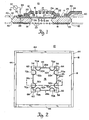
- acoustic transducer 10 which includes a perforated plate or member, electrode 12, having perforations 13 and being mounted to insulating layer 14.
- Movable plate or diaphragm 16 is mounted to substrate 18.
- Insulating layer 14 may be made of silicon oxide or silicon nitride.
- Substrate 18 may be silicon.
- the layer 20 on the bottom of substrate 18 is an etch stop layer, typically a P+ diffusion layer or silicon oxide or nitride.
- Perforated member 12 is a conductive electrode mounted on insulating layer 14 by means of footings 22. External connections are made through beam leads 24 attached to insulator layer 14 by means of anchors 25.
- Diaphragm 16 includes a pressure equalization slot 26 and is connected via conductor 28 to contact 30. Fluid entering slot 26 must follow a tortuous path 27 which bends or deflects and is lengthened in order to enter a perforation 13a. This is done intentionally to further increase the resistance seen by fluid flowing through slot 26 in order to enhance the low frequency performance of the transducer.
- An electric field is applied across perforated bridge electrode member 12 and diaphragm 16 by an a.c. or d.c. voltage source 32 which is connected through a series resistor 33 to contact 30.
- Perforated bridge electrode 12 is connected to readout circuitry (shown in Fig. 3 but not in Fig. 1).
- a dust filter 21 may be used to keep contaminant particles from reaching the transducer. Filter 21 may contain diamond shaped holes 23, Fig. 1A, whose overlap allows etching during fabrication to proceed essentially unimpeded.
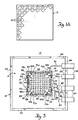
- the substrate 18 and diaphragm 16 and springs 54, 56, 58 and 60, Fig. 2, are all made of silicon.
- the dielectric fluid alternatively to being air, may be freon, oil, or any other insulating fluid.
- the transducer is constructed by micromachining photolithographic processes. The silicon areas to be protected during etching are doped with boron. An etchant such as EDP is used. Pressure equalizing passage, slot 26, permits any changes in pressure in the medium in which the transducer is immersed, e.g., air or water, to equalize on both sides of the diaphragm 16.
- V grooves 40, 42 are etched in substrate 18 during the fabrication process in order to allow easy separation of individual segments when that is desirable. These V grooves expose chamfered edges 44 which can be seen more clearly in Fig. 2, where the full course of slot 26 can be seen as including four sections 26a, b, c, d. Each section 26a-d of slot 26 takes on a curved portion 50a, 52a, 50b, 52b, 50c, 52c, and 50d, 52d, which define four springs 54, 56, 58 and 60. springs 54-60 are attached to substrate 18 by corner anchors 62, 64, 66 and 68, respectively. The remainder of diaphragm 16 is made independent from substrate 18 by virtue of slots 26a-d.
- slot 26 functions as a pressure equalization passage and as a means to separate the diaphragm 16 from substrate 18 and create springs 54-60.
- diaphragm 16 may be made of stiff material such as gold, nickel, copper, silicon, polycrystalline silicon, silicon dioxide, silicon nitride, silicon carbide, titanium, iron, chromium, platinum, palladium or aluminum, and alloys thereof, the needed flexibility can still be obtained and closely controlled by the separation of diaphragm 16 from substrate 18 and the shaping and sizing of springs 54-60 through the arrangement of slot 26.
- Bridge electrode member 12 may be made of the same materials.
- the corner anchors 62-68 and the diaphragm 16 may be P+ boron doped areas, while the surrounding portion of substrate 18 is an N- type region.
- the areas 70a, 72a, 70b, 72b, 70c, 72c, 70d, and 72d associated with each of the curved portions 50a, 52a -50d, 52d are also P+ boron doped regions. The PN junction thus created isolates the two regions electrically.
- Bridge electrode 12 is fastened to insulating layer 14 by bridge electrode footings 22. Electrical connection to diaphragm 16 is made through resistor 33 via corner anchor 64 and the anchor 25 of one of the beam leads 24. The connection to bridge electrode 12 is made through the anchors 25 of the other three beam electrodes 24 which actually interconnect through a source follower circuit 80 which includes FET transistor 82 and biasing resistors 84 and 86.
- the cavity compliance C CAV is three or more times greater than the spring compliance C sp so that the cavity volume will have a small effect on the sensitivity and resonant frequency.
- Equation (3) the minimum package volume V CAV which may be calculated from the air bulk modulus ( ⁇ c 2 ), the area of diaphragm 16, S(m 2 ) and the linear spring constant k sp (N/m) can be expressed as: V CAV ⁇ 3 ⁇ ⁇ ⁇ c 2 ⁇ S 2 k sp From equation (3) it can be seen that the necessary cavity volume rises vary rapidly with diaphragm diameter (d 4 ), assuming a constant spring constant. Thus if system volume is a constraint then Equation (3) may cause a constraint on the size of the diaphragm.
- Table I shows four design cases A-D for various cavity volumes, resonant frequencies, and diaphragm diameters. Table 1. Microphone design cases used for slot-width simulation. Case Cavity Volume (mm 3 ) Resonant Frequency (Hz) Diaphragm Diameter (mm) A 27 8 kHz 1 B 8 8 kHz 1 C 27 8 kHz 1.8 D 27 22 kHz 1.8
- Fig. 5 The results are graphically illustrated in Fig. 5, where the low frequency corner frequency or 3 dB roll-off point is the ordinate dimension and the width of the pressure equalization slot is the abscissa dimension. There it can be seen that the low frequency roll-off point decreases dramatically with decrease in slot width.
- a slot width of 0.1 to 10 microns provides good low end frequency response.
- a range of slot width from approximately 0.5 microns to 5.0 microns is preferred.
- Transducer 10 may be employed in a detection circuit 100, Fig. 6, in which the a.c. signal generator 32 operates as a local oscillator at, for example, 100 kilocycles or more. Then variations in the capacitance in transducer 10 causes modulation of the 100 KHz carrier wave. Amplifier 102 with feedback impedance 104 amplifies the modulator carrier signal in the 100 KHz band. After further amplification in amplifier 106 the signal is synchronously demodulated in demodulator 108 using a reference signal derived from a.c. signal generator 32 to extract the modulating signal representing the capacitance fluctuation of transducer 10. The detected signal representative of the variation in capacitance and thus the strength of the incident acoustic wave energy may be further treated in bandpass filter 110 to remove any d.c., carrier and carrier harmonic components, and ultimately provide the output signal V OUT .
- bandpass filter 110 to remove any d.c., carrier and carrier harmonic components
- d.c. source 32a provides a d.c. bias, V bias , through bias resistor 120 to transducer 10a.
- Gate resistor 122 sets the voltage at the gate 124 of FET 126.
- a bias voltage, V dd which can be the same as V bias is applied to the drain electrode 128 and the output 130 is taken from the source electrode 132 which is connected to ground 134 through source resistor 136.
Landscapes
- Physics & Mathematics (AREA)
- Engineering & Computer Science (AREA)
- Acoustics & Sound (AREA)
- Signal Processing (AREA)
- Electrostatic, Electromagnetic, Magneto- Strictive, And Variable-Resistance Transducers (AREA)
- Piezo-Electric Transducers For Audible Bands (AREA)
- Measuring Fluid Pressure (AREA)
Claims (11)
- Schallwandler mit: einem perforierten Element (12); einer beweglichen Membran (16), die vom perforierten Element beabstandet ist; Federmitteln (54-60), die das perforierte Element und die Membran zum beweglichen Abstützen der Membran relativ zum perforierten Element verbinden; einem Druckausgleichsschlitz (26) zum Steuern der Strömung von Fluid durch die Membran, wobei der Schlitz die Fluiddrücke auf entgegengesetzten Seiten der Membran ausgleicht; und Mitteln (30, 32) zum Anlegen eines elektrischen Feldes an das perforierte Element und die Membran zum Erzeugen eines Ausgangssignals, das die Änderung der Kapazität darstellt, die durch die Änderung des Zwischenraums zwischen dem perforierten Element und der Membran in Reaktion auf ein einfallendes Schallsignal induziert wird; dadurch gekennzeichnet, dass die Breite des Schlitzes (26) zwischen 0,1 und 10 Mikrometern zum Definieren des Niederfrequenzgangs des Wandlers liegt; und der Schlitz (26) in der Membran und die Perforationen (13) im perforierten Element unausgerichtet sind, um den Strömungsweg des Fluids vom Schlitz durch die Perforationen zu verändern und zu verlängern.
- Schallwandler nach Anspruch 1, wobei die Breite des Schlitzes (26) zwischen 0,5 und 5 Mikrometern liegt.
- Schallwandler nach Anspruch 1 oder 2, wobei ein beträchtlicher Teil des Schlitzes (26) mit dem perforierten Element (12) bedeckt ist.
- Schallwandler nach einem vorangehenden Anspruch, wobei der Schlitz (26) im Allgemeinen als Umfang der Membran (16) angeordnet ist.
- Schallwandler nach Anspruch 4, wobei der Schlitz (26) ungefähr der Länge des Umfangs der Membran (16) entspricht.
- Schallwandler nach einem vorangehenden Anspruch, wobei der Schlitz (26) eine Vielzahl von Abschnitten umfasst.
- Schallwandler nach einem vorangehenden Anspruch, wobei die Membran (16) einteilig mit einer Isolierschicht (14) ausgebildet ist und der Schlitz (16) zumindest teilweise zwischen der Membran und der Isolatorschicht ausgebildet ist.
- Schallwandler nach einem vorangehenden Anspruch, wobei der Schlitz (26) zumindest teilweise zwischen Teilen der Membran (16) ausgebildet ist.
- Schallwandler nach einem vorangehenden Anspruch, wobei die Membran (16), der Schlitz (26) und die Federmittel (54-60) auf einem Siliziumwafer (18) unter Verwendung von photolithographischen Mikrobearbeitungsverfahren hergestellt werden.
- Schallwandler nach einem vorangehenden Anspruch, wobei die Membran (16) und das perforierte Element (12) aus einem oder mehreren von Gold, Nickel, Eisen, Kupfer, Silizium, polykristallinem Silizium, Siliziumdioxid, Siliziumnitrid, Siliziumcarbid, Titan, Chrom, Platin, Palladium, Aluminium und Legierungen von diesen hergestellt sind.
- Schallwandler nach einem vorangehenden Anspruch und ferner mit einem von der Membran (16) beabstandeten Filter (21) zum Schützen der Membran vor Verunreinigungen in dem Fluid.
Applications Claiming Priority (3)
| Application Number | Priority Date | Filing Date | Title |
|---|---|---|---|
| US08/289,689 US5452268A (en) | 1994-08-12 | 1994-08-12 | Acoustic transducer with improved low frequency response |
| US289689 | 1994-08-12 | ||
| PCT/US1995/007520 WO1996005711A1 (en) | 1994-08-12 | 1995-06-12 | Acoustic transducer with improved low frequency response |
Publications (3)
| Publication Number | Publication Date |
|---|---|
| EP0775434A1 EP0775434A1 (de) | 1997-05-28 |
| EP0775434A4 EP0775434A4 (de) | 2002-11-27 |
| EP0775434B1 true EP0775434B1 (de) | 2007-08-08 |
Family
ID=23112653
Family Applications (1)
| Application Number | Title | Priority Date | Filing Date |
|---|---|---|---|
| EP95923850A Expired - Lifetime EP0775434B1 (de) | 1994-08-12 | 1995-06-12 | Schallwandler mit verbessertem niedrigem frequenzgang |
Country Status (9)
| Country | Link |
|---|---|
| US (1) | US5452268A (de) |
| EP (1) | EP0775434B1 (de) |
| JP (1) | JPH09508777A (de) |
| KR (1) | KR100232420B1 (de) |
| AT (1) | ATE369719T1 (de) |
| AU (1) | AU2827195A (de) |
| CA (1) | CA2197197C (de) |
| DE (1) | DE69535555D1 (de) |
| WO (1) | WO1996005711A1 (de) |
Families Citing this family (203)
| Publication number | Priority date | Publication date | Assignee | Title |
|---|---|---|---|---|
| US5446413A (en) * | 1994-05-20 | 1995-08-29 | Knowles Electronics, Inc. | Impedance circuit for a miniature hearing aid |
| US5889872A (en) * | 1996-07-02 | 1999-03-30 | Motorola, Inc. | Capacitive microphone and method therefor |
| US5859916A (en) * | 1996-07-12 | 1999-01-12 | Symphonix Devices, Inc. | Two stage implantable microphone |
| GB9617426D0 (en) | 1996-08-20 | 1996-10-02 | Domain Dynamics Ltd | Signal processing arrangements |
| US5854846A (en) | 1996-09-06 | 1998-12-29 | Northrop Grumman Corporation | Wafer fabricated electroacoustic transducer |
| US6520778B1 (en) | 1997-02-18 | 2003-02-18 | Formfactor, Inc. | Microelectronic contact structures, and methods of making same |
| US5870482A (en) * | 1997-02-25 | 1999-02-09 | Knowles Electronics, Inc. | Miniature silicon condenser microphone |
| SG86994A1 (en) * | 1997-07-11 | 2002-03-19 | Inst Of Microelectronics Nat U | Method of fabricating a silicon microphone |
| US6093144A (en) * | 1997-12-16 | 2000-07-25 | Symphonix Devices, Inc. | Implantable microphone having improved sensitivity and frequency response |
| US6249586B1 (en) * | 1998-01-21 | 2001-06-19 | Fachhochschule Furtwangen | Slot microphone |
| US6807734B2 (en) | 1998-02-13 | 2004-10-26 | Formfactor, Inc. | Microelectronic contact structures, and methods of making same |
| FI105880B (fi) * | 1998-06-18 | 2000-10-13 | Nokia Mobile Phones Ltd | Mikromekaanisen mikrofonin kiinnitys |
| JP2000022172A (ja) * | 1998-06-30 | 2000-01-21 | Matsushita Electric Ind Co Ltd | 変換装置及びその製造方法 |
| NL1009544C2 (nl) * | 1998-07-02 | 2000-01-10 | Microtronic Nederland Bv | Stelsel bestaande uit een microfoon en een voorversterker. |
| US6088463A (en) * | 1998-10-30 | 2000-07-11 | Microtronic A/S | Solid state silicon-based condenser microphone |
| CN1276259C (zh) * | 1998-12-02 | 2006-09-20 | 佛姆法克特股份有限公司 | 光刻接触元件 |
| US6255126B1 (en) * | 1998-12-02 | 2001-07-03 | Formfactor, Inc. | Lithographic contact elements |
| US6672875B1 (en) | 1998-12-02 | 2004-01-06 | Formfactor, Inc. | Spring interconnect structures |
| US6268015B1 (en) | 1998-12-02 | 2001-07-31 | Formfactor | Method of making and using lithographic contact springs |
| US6491968B1 (en) | 1998-12-02 | 2002-12-10 | Formfactor, Inc. | Methods for making spring interconnect structures |
| US6732588B1 (en) * | 1999-09-07 | 2004-05-11 | Sonionmems A/S | Pressure transducer |
| US6522762B1 (en) * | 1999-09-07 | 2003-02-18 | Microtronic A/S | Silicon-based sensor system |
| CA2291544A1 (en) | 1999-12-03 | 2001-06-03 | Dew Engineering And Development Limited | Prodder with force feedback |
| JP3611779B2 (ja) * | 1999-12-09 | 2005-01-19 | シャープ株式会社 | 電気信号−音響信号変換器及びその製造方法並びに電気信号−音響変換装置 |
| US6318497B1 (en) * | 2000-02-29 | 2001-11-20 | Benthos, Inc. | Pressure-sensitive switch, its method of calibration and use in a hydrophone array |
| EP1310136B1 (de) * | 2000-08-11 | 2006-03-22 | Knowles Electronics, LLC | Breitbandiger miniaturwandler |
| US6535460B2 (en) | 2000-08-11 | 2003-03-18 | Knowles Electronics, Llc | Miniature broadband acoustic transducer |
| US6987859B2 (en) | 2001-07-20 | 2006-01-17 | Knowles Electronics, Llc. | Raised microstructure of silicon based device |
| KR200218653Y1 (ko) * | 2000-11-01 | 2001-04-02 | 주식회사비에스이 | 일렉트렛 콘덴서 마이크로폰 |
| US7439616B2 (en) * | 2000-11-28 | 2008-10-21 | Knowles Electronics, Llc | Miniature silicon condenser microphone |
| US8617934B1 (en) | 2000-11-28 | 2013-12-31 | Knowles Electronics, Llc | Methods of manufacture of top port multi-part surface mount silicon condenser microphone packages |
| US7166910B2 (en) * | 2000-11-28 | 2007-01-23 | Knowles Electronics Llc | Miniature silicon condenser microphone |
| US7434305B2 (en) | 2000-11-28 | 2008-10-14 | Knowles Electronics, Llc. | Method of manufacturing a microphone |
| GB2386031B (en) | 2000-12-22 | 2004-08-18 | Bruel & Kjaer Sound & Vibratio | A highly stable micromachined capacitive transducer |
| WO2002052894A1 (en) * | 2000-12-22 | 2002-07-04 | Brüel & Kjær Sound & Vibration Measurement A/S | A micromachined capacitive transducer |
| US6847090B2 (en) * | 2001-01-24 | 2005-01-25 | Knowles Electronics, Llc | Silicon capacitive microphone |
| US7103196B2 (en) | 2001-03-12 | 2006-09-05 | Knowles Electronics, Llc. | Method for reducing distortion in a receiver |
| DK1241919T3 (da) * | 2001-03-12 | 2012-02-06 | Knowles Electronics Llc | Fremgangsmåde til reducering af forvrængning i en modtager |
| GB0107404D0 (en) * | 2001-03-23 | 2001-05-16 | Koninkl Philips Electronics Nv | Display substrate and display device |
| US7065224B2 (en) | 2001-09-28 | 2006-06-20 | Sonionmicrotronic Nederland B.V. | Microphone for a hearing aid or listening device with improved internal damping and foreign material protection |
| US7023066B2 (en) * | 2001-11-20 | 2006-04-04 | Knowles Electronics, Llc. | Silicon microphone |
| AU2002365352A1 (en) * | 2001-11-27 | 2003-06-10 | Corporation For National Research Initiatives | A miniature condenser microphone and fabrication method therefor |
| DE10205585A1 (de) * | 2002-02-11 | 2003-08-28 | Infineon Technologies Ag | Mikromechanisches Bauelement und Verfahren zu dessen Herstellung |
| FI118505B (fi) * | 2002-06-04 | 2007-11-30 | Aspocomp Oy | Monikerrospiirilevyrakenteeseen muodostettu akustisesti aktiivinen elementti, menetelmä akustisesti aktiivisen elementin muodostamiseksi monikerrospiirilevyrakenteeseen sekä monikerrospiirilevyrakenne |
| US6781231B2 (en) * | 2002-09-10 | 2004-08-24 | Knowles Electronics Llc | Microelectromechanical system package with environmental and interference shield |
| US6667189B1 (en) | 2002-09-13 | 2003-12-23 | Institute Of Microelectronics | High performance silicon condenser microphone with perforated single crystal silicon backplate |
| US7142682B2 (en) * | 2002-12-20 | 2006-11-28 | Sonion Mems A/S | Silicon-based transducer for use in hearing instruments and listening devices |
| US7049051B2 (en) * | 2003-01-23 | 2006-05-23 | Akustica, Inc. | Process for forming and acoustically connecting structures on a substrate |
| US7280435B2 (en) * | 2003-03-06 | 2007-10-09 | General Electric Company | Switching circuitry for reconfigurable arrays of sensor elements |
| US7257051B2 (en) * | 2003-03-06 | 2007-08-14 | General Electric Company | Integrated interface electronics for reconfigurable sensor array |
| US6865140B2 (en) * | 2003-03-06 | 2005-03-08 | General Electric Company | Mosaic arrays using micromachined ultrasound transducers |
| US7353056B2 (en) * | 2003-03-06 | 2008-04-01 | General Electric Company | Optimized switching configurations for reconfigurable arrays of sensor elements |
| US7313053B2 (en) * | 2003-03-06 | 2007-12-25 | General Electric Company | Method and apparatus for controlling scanning of mosaic sensor array |
| US7443765B2 (en) * | 2003-03-06 | 2008-10-28 | General Electric Company | Reconfigurable linear sensor arrays for reduced channel count |
| JP2004356707A (ja) * | 2003-05-27 | 2004-12-16 | Hosiden Corp | 音響検出機構 |
| CN1883020B (zh) * | 2003-11-20 | 2011-02-02 | 松下电器产业株式会社 | 驻极体和驻极体电容器 |
| US7030536B2 (en) * | 2003-12-29 | 2006-04-18 | General Electric Company | Micromachined ultrasonic transducer cells having compliant support structure |
| JP4201723B2 (ja) * | 2004-02-13 | 2008-12-24 | 東京エレクトロン株式会社 | 容量検知型センサ素子 |
| US7706554B2 (en) * | 2004-03-03 | 2010-04-27 | Panasonic Corporation | Electret condenser |
| EP1722595A4 (de) * | 2004-03-05 | 2010-07-28 | Panasonic Corp | Elektret-kondenser |
| DE102004011149B3 (de) * | 2004-03-08 | 2005-11-10 | Infineon Technologies Ag | Mikrophon und Verfahren zur Herstellung eines Mikrophons |
| WO2005086535A1 (ja) * | 2004-03-09 | 2005-09-15 | Matsushita Electric Industrial Co., Ltd. | エレクトレットコンデンサーマイクロホン |
| TWI260938B (en) * | 2004-10-01 | 2006-08-21 | Ind Tech Res Inst | Dynamic pressure sensing structure |
| US7415121B2 (en) * | 2004-10-29 | 2008-08-19 | Sonion Nederland B.V. | Microphone with internal damping |
| US7329933B2 (en) * | 2004-10-29 | 2008-02-12 | Silicon Matrix Pte. Ltd. | Silicon microphone with softly constrained diaphragm |
| US7346178B2 (en) * | 2004-10-29 | 2008-03-18 | Silicon Matrix Pte. Ltd. | Backplateless silicon microphone |
| JP4539450B2 (ja) | 2004-11-04 | 2010-09-08 | オムロン株式会社 | 容量型振動センサ及びその製造方法 |
| US7795695B2 (en) | 2005-01-27 | 2010-09-14 | Analog Devices, Inc. | Integrated microphone |
| DE102005008512B4 (de) | 2005-02-24 | 2016-06-23 | Epcos Ag | Elektrisches Modul mit einem MEMS-Mikrofon |
| DE102005008511B4 (de) | 2005-02-24 | 2019-09-12 | Tdk Corporation | MEMS-Mikrofon |
| US7152481B2 (en) * | 2005-04-13 | 2006-12-26 | Yunlong Wang | Capacitive micromachined acoustic transducer |
| US20070071268A1 (en) * | 2005-08-16 | 2007-03-29 | Analog Devices, Inc. | Packaged microphone with electrically coupled lid |
| US7825484B2 (en) * | 2005-04-25 | 2010-11-02 | Analog Devices, Inc. | Micromachined microphone and multisensor and method for producing same |
| US7885423B2 (en) * | 2005-04-25 | 2011-02-08 | Analog Devices, Inc. | Support apparatus for microphone diaphragm |
| US7449356B2 (en) * | 2005-04-25 | 2008-11-11 | Analog Devices, Inc. | Process of forming a microphone using support member |
| CN100455142C (zh) * | 2005-06-03 | 2009-01-21 | 瑞声声学科技(深圳)有限公司 | 电容式微机电结构声音传感器 |
| US20060280319A1 (en) * | 2005-06-08 | 2006-12-14 | General Mems Corporation | Micromachined Capacitive Microphone |
| US20070040231A1 (en) * | 2005-08-16 | 2007-02-22 | Harney Kieran P | Partially etched leadframe packages having different top and bottom topologies |
| US7961897B2 (en) * | 2005-08-23 | 2011-06-14 | Analog Devices, Inc. | Microphone with irregular diaphragm |
| US8477983B2 (en) * | 2005-08-23 | 2013-07-02 | Analog Devices, Inc. | Multi-microphone system |
| US8351632B2 (en) * | 2005-08-23 | 2013-01-08 | Analog Devices, Inc. | Noise mitigating microphone system and method |
| US8130979B2 (en) * | 2005-08-23 | 2012-03-06 | Analog Devices, Inc. | Noise mitigating microphone system and method |
| JP2007081614A (ja) * | 2005-09-13 | 2007-03-29 | Star Micronics Co Ltd | コンデンサマイクロホン |
| JP2007116650A (ja) * | 2005-09-26 | 2007-05-10 | Yamaha Corp | ダイヤフラム及びダイヤフラムの製造方法並びにコンデンサマイクロホン |
| US20070121972A1 (en) * | 2005-09-26 | 2007-05-31 | Yamaha Corporation | Capacitor microphone and diaphragm therefor |
| US20070090732A1 (en) * | 2005-10-25 | 2007-04-26 | The Charles Stark Draper Laboratory, Inc. | Systems, methods and devices relating to actuatably moveable machines |
| US7566582B2 (en) * | 2005-10-25 | 2009-07-28 | The Charles Stark Draper Laboratory, Inc. | Systems, methods and devices relating to actuatably moveable machines |
| DE102005053765B4 (de) | 2005-11-10 | 2016-04-14 | Epcos Ag | MEMS-Package und Verfahren zur Herstellung |
| DE102005053767B4 (de) | 2005-11-10 | 2014-10-30 | Epcos Ag | MEMS-Mikrofon, Verfahren zur Herstellung und Verfahren zum Einbau |
| DE102005056759A1 (de) * | 2005-11-29 | 2007-05-31 | Robert Bosch Gmbh | Mikromechanische Struktur zum Empfang und/oder zur Erzeugung von akustischen Signalen, Verfahren zur Herstellung einer mikromechanischen Struktur und Verwendung einer mikromechanischen Struktur |
| WO2007085017A1 (en) * | 2006-01-20 | 2007-07-26 | Analog Devices, Inc. | Support apparatus for condenser microphone diaphragm |
| JP4811035B2 (ja) * | 2006-01-31 | 2011-11-09 | パナソニック電工株式会社 | 音響センサ |
| TW200738028A (en) * | 2006-02-24 | 2007-10-01 | Yamaha Corp | Condenser microphone |
| TW200746868A (en) * | 2006-02-24 | 2007-12-16 | Yamaha Corp | Condenser microphone |
| JP2007228345A (ja) * | 2006-02-24 | 2007-09-06 | Yamaha Corp | コンデンサマイクロホン |
| JP4605470B2 (ja) * | 2006-03-31 | 2011-01-05 | ヤマハ株式会社 | コンデンサマイクロホン |
| JP4737720B2 (ja) * | 2006-03-06 | 2011-08-03 | ヤマハ株式会社 | ダイヤフラム及びその製造方法並びにそのダイヤフラムを有するコンデンサマイクロホン及びその製造方法 |
| GB2443756B (en) * | 2006-02-24 | 2010-03-17 | Wolfson Microelectronics Plc | MEMS device |
| GB0605576D0 (en) * | 2006-03-20 | 2006-04-26 | Oligon Ltd | MEMS device |
| TW200746869A (en) | 2006-03-29 | 2007-12-16 | Yamaha Corp | Condenser microphone |
| JP4605544B2 (ja) * | 2006-03-29 | 2011-01-05 | ヤマハ株式会社 | コンデンサマイクロホン |
| ATE471635T1 (de) * | 2006-03-30 | 2010-07-15 | Sonion Mems As | Akustischer einchip-mems-wandler und herstellungsverfahren |
| JP4742972B2 (ja) * | 2006-04-27 | 2011-08-10 | オムロン株式会社 | マイクロフォンの製造方法 |
| JP4480728B2 (ja) * | 2006-06-09 | 2010-06-16 | パナソニック株式会社 | Memsマイクの製造方法 |
| US8081783B2 (en) * | 2006-06-20 | 2011-12-20 | Industrial Technology Research Institute | Miniature acoustic transducer |
| US8344487B2 (en) * | 2006-06-29 | 2013-01-01 | Analog Devices, Inc. | Stress mitigation in packaged microchips |
| KR20080005854A (ko) | 2006-07-10 | 2008-01-15 | 야마하 가부시키가이샤 | 압력 센서 및 그의 제조 방법 |
| US20080019543A1 (en) * | 2006-07-19 | 2008-01-24 | Yamaha Corporation | Silicon microphone and manufacturing method therefor |
| WO2008014324A2 (en) * | 2006-07-25 | 2008-01-31 | Analog Devices, Inc. | Multiple microphone system |
| US20080042223A1 (en) * | 2006-08-17 | 2008-02-21 | Lu-Lee Liao | Microelectromechanical system package and method for making the same |
| US20080075308A1 (en) * | 2006-08-30 | 2008-03-27 | Wen-Chieh Wei | Silicon condenser microphone |
| US20080083957A1 (en) * | 2006-10-05 | 2008-04-10 | Wen-Chieh Wei | Micro-electromechanical system package |
| JP4144640B2 (ja) | 2006-10-13 | 2008-09-03 | オムロン株式会社 | 振動センサの製造方法 |
| US7894622B2 (en) | 2006-10-13 | 2011-02-22 | Merry Electronics Co., Ltd. | Microphone |
| GB2443458B (en) * | 2006-10-31 | 2009-09-16 | Motorola Inc | Wind filter for use with a microphone |
| DE102006055147B4 (de) | 2006-11-03 | 2011-01-27 | Infineon Technologies Ag | Schallwandlerstruktur und Verfahren zur Herstellung einer Schallwandlerstruktur |
| US8165323B2 (en) | 2006-11-28 | 2012-04-24 | Zhou Tiansheng | Monolithic capacitive transducer |
| TW200847827A (en) * | 2006-11-30 | 2008-12-01 | Analog Devices Inc | Microphone system with silicon microphone secured to package lid |
| EP1931173B1 (de) | 2006-12-06 | 2011-07-20 | Electronics and Telecommunications Research Institute | Kondensatormikrofon mit Membran mit Biegescharnier und Herstellungsverfahren dafür |
| US20080144863A1 (en) * | 2006-12-15 | 2008-06-19 | Fazzio R Shane | Microcap packaging of micromachined acoustic devices |
| US8121315B2 (en) * | 2007-03-21 | 2012-02-21 | Goer Tek Inc. | Condenser microphone chip |
| WO2008134530A2 (en) | 2007-04-25 | 2008-11-06 | University Of Florida Research Foundation, Inc. | A capacitive microphone with integrated cavity |
| US7694610B2 (en) * | 2007-06-27 | 2010-04-13 | Siemens Medical Solutions Usa, Inc. | Photo-multiplier tube removal tool |
| JP2009081624A (ja) * | 2007-09-26 | 2009-04-16 | Rohm Co Ltd | 半導体センサ装置 |
| EP2043385A2 (de) | 2007-09-28 | 2009-04-01 | Yamaha Corporation | Schwingungswandler und entsprechendes Herstellungsverfahren |
| US8045733B2 (en) * | 2007-10-05 | 2011-10-25 | Shandong Gettop Acoustic Co., Ltd. | Silicon microphone with enhanced impact proof structure using bonding wires |
| US7888754B2 (en) | 2007-12-28 | 2011-02-15 | Yamaha Corporation | MEMS transducer |
| US8144906B2 (en) * | 2008-05-21 | 2012-03-27 | Akustica, Inc. | Wind immune microphone |
| WO2010002887A2 (en) * | 2008-06-30 | 2010-01-07 | The Regents Of The University Of Michigan | Piezoelectric memes microphone |
| US10170685B2 (en) | 2008-06-30 | 2019-01-01 | The Regents Of The University Of Michigan | Piezoelectric MEMS microphone |
| JP5332373B2 (ja) * | 2008-07-25 | 2013-11-06 | オムロン株式会社 | 静電容量型振動センサ |
| JP2010081192A (ja) * | 2008-09-25 | 2010-04-08 | Rohm Co Ltd | Memsセンサ |
| US8134215B2 (en) * | 2008-10-09 | 2012-03-13 | United Microelectronics Corp. | MEMS diaphragm |
| IT1392742B1 (it) * | 2008-12-23 | 2012-03-16 | St Microelectronics Rousset | Trasduttore acustico integrato in tecnologia mems e relativo processo di fabbricazione |
| EP2207190B9 (de) * | 2009-01-08 | 2014-09-24 | Epcos AG | Gefederte Vorrichtung |
| US8325951B2 (en) | 2009-01-20 | 2012-12-04 | General Mems Corporation | Miniature MEMS condenser microphone packages and fabrication method thereof |
| US8472648B2 (en) * | 2009-01-20 | 2013-06-25 | General Mems Corporation | Miniature MEMS condenser microphone package and fabrication method thereof |
| JP5286153B2 (ja) * | 2009-04-28 | 2013-09-11 | アズビル株式会社 | 圧力センサの製造方法 |
| JP5377066B2 (ja) * | 2009-05-08 | 2013-12-25 | キヤノン株式会社 | 静電容量型機械電気変換素子及びその製法 |
| CN201467442U (zh) * | 2009-05-15 | 2010-05-12 | 瑞声声学科技(常州)有限公司 | 电容麦克风 |
| CN102428711A (zh) * | 2009-05-18 | 2012-04-25 | 美商楼氏电子有限公司 | 具有降低的振动灵敏度的麦克风 |
| WO2010139050A1 (en) | 2009-06-01 | 2010-12-09 | Tiansheng Zhou | Mems micromirror and micromirror array |
| DE102009028177A1 (de) * | 2009-07-31 | 2011-02-10 | Robert Bosch Gmbh | Bauelement mit einer mikromechanischen Mikrofonstruktur und Verfahren zur Herstellung eines solchen Bauelements |
| EP2309241B1 (de) * | 2009-10-07 | 2016-11-30 | ams international AG | MEMS-Drucksensor |
| US8304846B2 (en) | 2009-12-31 | 2012-11-06 | Texas Instruments Incorporated | Silicon microphone with integrated back side cavity |
| US9123323B2 (en) * | 2010-06-04 | 2015-09-01 | John P. Keady | Method and structure for inducing acoustic signals and attenuating acoustic signals |
| EP2420470B1 (de) * | 2010-08-18 | 2015-10-14 | Nxp B.V. | MEMS-Mikrofon |
| US9036231B2 (en) | 2010-10-20 | 2015-05-19 | Tiansheng ZHOU | Micro-electro-mechanical systems micromirrors and micromirror arrays |
| US10551613B2 (en) | 2010-10-20 | 2020-02-04 | Tiansheng ZHOU | Micro-electro-mechanical systems micromirrors and micromirror arrays |
| DE102011002457A1 (de) * | 2011-01-05 | 2012-07-05 | Robert Bosch Gmbh | Mikromechanische Mikrofoneinrichtung und Verfahren zum Herstellen einer mikromechanischen Mikrofoneinrichtung |
| JP5872163B2 (ja) | 2011-01-07 | 2016-03-01 | オムロン株式会社 | 音響トランスデューサ、および該音響トランスデューサを利用したマイクロフォン |
| US9380380B2 (en) | 2011-01-07 | 2016-06-28 | Stmicroelectronics S.R.L. | Acoustic transducer and interface circuit |
| WO2012122696A1 (en) * | 2011-03-11 | 2012-09-20 | Goertek Inc. | Cmos compatible silicon differential condenser microphone and method for manufacturing the same |
| WO2013066343A1 (en) | 2011-11-04 | 2013-05-10 | Knowles Electronics, Llc | Embedded dielectric as a barrier in an acoustic device and method of manufacture |
| DE102011086765A1 (de) * | 2011-11-22 | 2013-05-23 | Robert Bosch Gmbh | Chip mit mikro-elektromechanischer Struktur und Verfahren zum Herstellen eines Chips mit mikro-elektromechanischer Struktur |
| US9385634B2 (en) | 2012-01-26 | 2016-07-05 | Tiansheng ZHOU | Rotational type of MEMS electrostatic actuator |
| JP5177309B1 (ja) * | 2012-01-31 | 2013-04-03 | オムロン株式会社 | 静電容量型センサ |
| US8983097B2 (en) * | 2012-02-29 | 2015-03-17 | Infineon Technologies Ag | Adjustable ventilation openings in MEMS structures |
| JP5861497B2 (ja) * | 2012-02-29 | 2016-02-16 | オムロン株式会社 | センサ装置 |
| US9002037B2 (en) | 2012-02-29 | 2015-04-07 | Infineon Technologies Ag | MEMS structure with adjustable ventilation openings |
| US8983101B2 (en) * | 2012-05-22 | 2015-03-17 | Shure Acquisition Holdings, Inc. | Earphone assembly |
| US9078063B2 (en) | 2012-08-10 | 2015-07-07 | Knowles Electronics, Llc | Microphone assembly with barrier to prevent contaminant infiltration |
| DE102012107457B4 (de) * | 2012-08-14 | 2017-05-24 | Tdk Corporation | MEMS-Bauelement mit Membran und Verfahren zur Herstellung |
| JP5987572B2 (ja) * | 2012-09-11 | 2016-09-07 | オムロン株式会社 | 音響トランスデューサ |
| US9676614B2 (en) | 2013-02-01 | 2017-06-13 | Analog Devices, Inc. | MEMS device with stress relief structures |
| US9338559B2 (en) | 2013-04-16 | 2016-05-10 | Invensense, Inc. | Microphone system with a stop member |
| US9681234B2 (en) * | 2013-05-09 | 2017-06-13 | Shanghai Ic R&D Center Co., Ltd | MEMS microphone structure and method of manufacturing the same |
| DE102013106353B4 (de) * | 2013-06-18 | 2018-06-28 | Tdk Corporation | Verfahren zum Aufbringen einer strukturierten Beschichtung auf ein Bauelement |
| US9024396B2 (en) | 2013-07-12 | 2015-05-05 | Infineon Technologies Ag | Device with MEMS structure and ventilation path in support structure |
| US9494477B2 (en) * | 2014-03-31 | 2016-11-15 | Infineon Technologies Ag | Dynamic pressure sensor |
| US9888325B2 (en) * | 2014-04-01 | 2018-02-06 | Robert Bosch Gmbh | Doped substrate regions in MEMS microphones |
| KR101462375B1 (ko) * | 2014-06-30 | 2014-11-17 | 한국기계연구원 | Mems 마이크로폰 |
| CN104113810A (zh) * | 2014-07-18 | 2014-10-22 | 瑞声声学科技(深圳)有限公司 | Mems麦克风及其制备方法与电子设备 |
| CN204046818U (zh) | 2014-07-28 | 2014-12-24 | 瑞声声学科技(深圳)有限公司 | 电容mems麦克风 |
| EP3186979A4 (de) * | 2014-08-27 | 2018-02-28 | Goertek. Inc | Mems-vorrichtung mit ventilmechanismus |
| JP6467837B2 (ja) | 2014-09-25 | 2019-02-13 | オムロン株式会社 | 音響トランスデューサ及びマイクロフォン |
| US10006824B2 (en) * | 2014-09-29 | 2018-06-26 | Invensense, Inc. | Microelectromechanical systems (MEMS) pressure sensor having a leakage path to a cavity |
| US10167189B2 (en) | 2014-09-30 | 2019-01-01 | Analog Devices, Inc. | Stress isolation platform for MEMS devices |
| US10277968B2 (en) * | 2015-01-05 | 2019-04-30 | Goertek.Inc | Microphone with dustproof through holes |
| US9794661B2 (en) | 2015-08-07 | 2017-10-17 | Knowles Electronics, Llc | Ingress protection for reducing particle infiltration into acoustic chamber of a MEMS microphone package |
| US10131538B2 (en) | 2015-09-14 | 2018-11-20 | Analog Devices, Inc. | Mechanically isolated MEMS device |
| US9888307B2 (en) | 2015-12-04 | 2018-02-06 | Apple Inc. | Microphone assembly having an acoustic leak path |
| US9516421B1 (en) | 2015-12-18 | 2016-12-06 | Knowles Electronics, Llc | Acoustic sensing apparatus and method of manufacturing the same |
| US10770646B2 (en) * | 2016-03-01 | 2020-09-08 | Qualcomm Incorporated | Manufacturing method for flexible PMUT array |
| JP6809008B2 (ja) | 2016-07-08 | 2021-01-06 | オムロン株式会社 | Mems構造及び、mems構造を有する静電容量型センサ、圧電型センサ、音響センサ |
| US10616690B2 (en) * | 2016-08-22 | 2020-04-07 | Goertek Inc. | Capacitive MEMS microphone and electronic apparatus |
| US10075783B2 (en) | 2016-09-23 | 2018-09-11 | Apple Inc. | Acoustically summed reference microphone for active noise control |
| KR102371228B1 (ko) * | 2016-11-24 | 2022-03-04 | 현대자동차 주식회사 | 마이크로폰 및 이의 제조방법 |
| US10948688B2 (en) | 2017-01-23 | 2021-03-16 | Google Llc | Optical circuit switch mirror array crack protection |
| KR102212575B1 (ko) * | 2017-02-02 | 2021-02-04 | 현대자동차 주식회사 | 마이크로폰 및 그 제조 방법 |
| CN108810773A (zh) * | 2017-04-26 | 2018-11-13 | 中芯国际集成电路制造(上海)有限公司 | 麦克风及其制造方法 |
| GB201708348D0 (en) * | 2017-04-28 | 2017-07-12 | Cirrus Logic Int Semiconductor Ltd | MEMS devices and processes |
| CN107071672B (zh) * | 2017-05-22 | 2020-08-21 | 潍坊歌尔微电子有限公司 | 一种压电式麦克风 |
| DE102017213520A1 (de) * | 2017-08-03 | 2019-02-07 | Infineon Technologies Ag | Referenzkammer für einen Fluidsensor, Fluidsensor, Vorrichtung mit einem Fluidsensor und Verfahren zum Bereitstellen einer Referenzkammer sowie zum Bestimmen einer Atmosphäreneigenschaft in einer Referenzkammer |
| CN207820227U (zh) * | 2018-01-08 | 2018-09-04 | 瑞声声学科技(深圳)有限公司 | Mems麦克风 |
| CN112334867B (zh) | 2018-05-24 | 2025-11-11 | 纽约州立大学研究基金会 | 电容传感器 |
| US11467025B2 (en) | 2018-08-17 | 2022-10-11 | Invensense, Inc. | Techniques for alternate pressure equalization of a sensor |
| US11197104B2 (en) | 2019-01-25 | 2021-12-07 | Knowles Electronics, Llc | MEMS transducer including free plate diaphragm with spring members |
| US11417611B2 (en) | 2020-02-25 | 2022-08-16 | Analog Devices International Unlimited Company | Devices and methods for reducing stress on circuit components |
| US11981560B2 (en) | 2020-06-09 | 2024-05-14 | Analog Devices, Inc. | Stress-isolated MEMS device comprising substrate having cavity and method of manufacture |
| US11490190B1 (en) | 2021-05-07 | 2022-11-01 | Apple Inc. | Speaker with multiple resonators |
| US11451902B1 (en) | 2021-05-07 | 2022-09-20 | Apple Inc. | Speaker with vented resonator |
| US12072252B2 (en) * | 2021-09-24 | 2024-08-27 | Apple Inc. | Gap-increasing capacitive pressure sensor for increased range |
Family Cites Families (5)
| Publication number | Priority date | Publication date | Assignee | Title |
|---|---|---|---|---|
| JPH0726887B2 (ja) * | 1986-05-31 | 1995-03-29 | 株式会社堀場製作所 | コンデンサマイクロフオン型検出器用ダイアフラム |
| DE3807251A1 (de) * | 1988-03-05 | 1989-09-14 | Sennheiser Electronic | Kapazitiver schallwandler |
| US5146435A (en) * | 1989-12-04 | 1992-09-08 | The Charles Stark Draper Laboratory, Inc. | Acoustic transducer |
| NL9101563A (nl) * | 1991-09-17 | 1993-04-16 | Microtel Bv | Elektroacoustische transducent van het elektreet type. |
| US5303210A (en) * | 1992-10-29 | 1994-04-12 | The Charles Stark Draper Laboratory, Inc. | Integrated resonant cavity acoustic transducer |
-
1994
- 1994-08-12 US US08/289,689 patent/US5452268A/en not_active Expired - Lifetime
-
1995
- 1995-06-12 KR KR1019970700926A patent/KR100232420B1/ko not_active Expired - Fee Related
- 1995-06-12 AT AT95923850T patent/ATE369719T1/de not_active IP Right Cessation
- 1995-06-12 AU AU28271/95A patent/AU2827195A/en not_active Abandoned
- 1995-06-12 CA CA002197197A patent/CA2197197C/en not_active Expired - Fee Related
- 1995-06-12 JP JP8507292A patent/JPH09508777A/ja active Pending
- 1995-06-12 EP EP95923850A patent/EP0775434B1/de not_active Expired - Lifetime
- 1995-06-12 WO PCT/US1995/007520 patent/WO1996005711A1/en not_active Ceased
- 1995-06-12 DE DE69535555T patent/DE69535555D1/de not_active Expired - Lifetime
Also Published As
| Publication number | Publication date |
|---|---|
| ATE369719T1 (de) | 2007-08-15 |
| EP0775434A1 (de) | 1997-05-28 |
| KR100232420B1 (ko) | 1999-12-01 |
| EP0775434A4 (de) | 2002-11-27 |
| DE69535555D1 (de) | 2007-09-20 |
| CA2197197C (en) | 1999-02-23 |
| AU2827195A (en) | 1996-03-07 |
| US5452268A (en) | 1995-09-19 |
| WO1996005711A1 (en) | 1996-02-22 |
| CA2197197A1 (en) | 1996-02-22 |
| KR970705325A (ko) | 1997-09-06 |
| JPH09508777A (ja) | 1997-09-02 |
Similar Documents
| Publication | Publication Date | Title |
|---|---|---|
| EP0775434B1 (de) | Schallwandler mit verbessertem niedrigem frequenzgang | |
| US5596222A (en) | Wafer of transducer chips | |
| US5146435A (en) | Acoustic transducer | |
| US4558184A (en) | Integrated capacitive transducer | |
| CN104284290B (zh) | 具有mems结构和在支撑结构中的通风路径的装置 | |
| CN103517169B (zh) | 具有可调节通风开口的mems结构及mems装置 | |
| US3748571A (en) | Pressure sensitive transducers employing capacitive and resistive variations | |
| US6535460B2 (en) | Miniature broadband acoustic transducer | |
| Kronast et al. | Single-chip condenser microphone using porous silicon as sacrificial layer for the air gap | |
| US8276254B2 (en) | Surface micromachined differential microphone | |
| US7400737B2 (en) | Miniature condenser microphone and fabrication method therefor | |
| KR101385627B1 (ko) | 미니어처 비-방향성 마이크로폰 | |
| US20120328132A1 (en) | Perforated Miniature Silicon Microphone | |
| US20030034536A1 (en) | Micromachined capacitive electrical component | |
| US12497283B2 (en) | MEMS die and MEMS-based sensor | |
| EP3247134A1 (de) | Akustischer mems-wandler mit kammfingerelektroden und zugehöriges herstellungsverfahren | |
| GB2212274A (en) | Capacitive accelerometer and its fabrication method | |
| EP3322201B1 (de) | Kapazitiver wandler und akustischer sensor | |
| US4567382A (en) | Electret transducer and a method for manufacturing an assembly of backplate, electret foil and diaphragm plate | |
| JP4737535B2 (ja) | コンデンサマイクロホン | |
| JP2019204987A (ja) | トランスデューサ装置 |
Legal Events
| Date | Code | Title | Description |
|---|---|---|---|
| PUAI | Public reference made under article 153(3) epc to a published international application that has entered the european phase |
Free format text: ORIGINAL CODE: 0009012 |
|
| 17P | Request for examination filed |
Effective date: 19970227 |
|
| AK | Designated contracting states |
Kind code of ref document: A1 Designated state(s): AT BE DE FR GB IT |
|
| A4 | Supplementary search report drawn up and despatched |
Effective date: 20021015 |
|
| AK | Designated contracting states |
Kind code of ref document: A4 Designated state(s): AT BE DE FR GB IT |
|
| 17Q | First examination report despatched |
Effective date: 20050627 |
|
| GRAP | Despatch of communication of intention to grant a patent |
Free format text: ORIGINAL CODE: EPIDOSNIGR1 |
|
| GRAS | Grant fee paid |
Free format text: ORIGINAL CODE: EPIDOSNIGR3 |
|
| GRAA | (expected) grant |
Free format text: ORIGINAL CODE: 0009210 |
|
| AK | Designated contracting states |
Kind code of ref document: B1 Designated state(s): AT BE DE FR GB IT |
|
| REG | Reference to a national code |
Ref country code: GB Ref legal event code: FG4D |
|
| REF | Corresponds to: |
Ref document number: 69535555 Country of ref document: DE Date of ref document: 20070920 Kind code of ref document: P |
|
| PG25 | Lapsed in a contracting state [announced via postgrant information from national office to epo] |
Ref country code: AT Free format text: LAPSE BECAUSE OF FAILURE TO SUBMIT A TRANSLATION OF THE DESCRIPTION OR TO PAY THE FEE WITHIN THE PRESCRIBED TIME-LIMIT Effective date: 20070808 |
|
| PG25 | Lapsed in a contracting state [announced via postgrant information from national office to epo] |
Ref country code: BE Free format text: LAPSE BECAUSE OF FAILURE TO SUBMIT A TRANSLATION OF THE DESCRIPTION OR TO PAY THE FEE WITHIN THE PRESCRIBED TIME-LIMIT Effective date: 20070808 |
|
| EN | Fr: translation not filed | ||
| PLBE | No opposition filed within time limit |
Free format text: ORIGINAL CODE: 0009261 |
|
| STAA | Information on the status of an ep patent application or granted ep patent |
Free format text: STATUS: NO OPPOSITION FILED WITHIN TIME LIMIT |
|
| 26N | No opposition filed |
Effective date: 20080509 |
|
| PG25 | Lapsed in a contracting state [announced via postgrant information from national office to epo] |
Ref country code: DE Free format text: LAPSE BECAUSE OF FAILURE TO SUBMIT A TRANSLATION OF THE DESCRIPTION OR TO PAY THE FEE WITHIN THE PRESCRIBED TIME-LIMIT Effective date: 20071109 |
|
| GBPC | Gb: european patent ceased through non-payment of renewal fee |
Effective date: 20080612 |
|
| PG25 | Lapsed in a contracting state [announced via postgrant information from national office to epo] |
Ref country code: GB Free format text: LAPSE BECAUSE OF NON-PAYMENT OF DUE FEES Effective date: 20080612 |
|
| PG25 | Lapsed in a contracting state [announced via postgrant information from national office to epo] |
Ref country code: IT Free format text: LAPSE BECAUSE OF NON-PAYMENT OF DUE FEES Effective date: 20080630 |
|
| PG25 | Lapsed in a contracting state [announced via postgrant information from national office to epo] |
Ref country code: FR Free format text: LAPSE BECAUSE OF FAILURE TO SUBMIT A TRANSLATION OF THE DESCRIPTION OR TO PAY THE FEE WITHIN THE PRESCRIBED TIME-LIMIT Effective date: 20080404 |