EP0773389A1 - Linearantrieb mit Spindelabstützungen - Google Patents
Linearantrieb mit Spindelabstützungen Download PDFInfo
- Publication number
- EP0773389A1 EP0773389A1 EP95308066A EP95308066A EP0773389A1 EP 0773389 A1 EP0773389 A1 EP 0773389A1 EP 95308066 A EP95308066 A EP 95308066A EP 95308066 A EP95308066 A EP 95308066A EP 0773389 A1 EP0773389 A1 EP 0773389A1
- Authority
- EP
- European Patent Office
- Prior art keywords
- support
- slider
- feed screw
- support member
- pair
- Prior art date
- Legal status (The legal status is an assumption and is not a legal conclusion. Google has not performed a legal analysis and makes no representation as to the accuracy of the status listed.)
- Granted
Links
Images


Classifications
-
- B—PERFORMING OPERATIONS; TRANSPORTING
- B23—MACHINE TOOLS; METAL-WORKING NOT OTHERWISE PROVIDED FOR
- B23Q—DETAILS, COMPONENTS, OR ACCESSORIES FOR MACHINE TOOLS, e.g. ARRANGEMENTS FOR COPYING OR CONTROLLING; MACHINE TOOLS IN GENERAL CHARACTERISED BY THE CONSTRUCTION OF PARTICULAR DETAILS OR COMPONENTS; COMBINATIONS OR ASSOCIATIONS OF METAL-WORKING MACHINES, NOT DIRECTED TO A PARTICULAR RESULT
- B23Q5/00—Driving or feeding mechanisms; Control arrangements therefor
- B23Q5/22—Feeding members carrying tools or work
- B23Q5/34—Feeding other members supporting tools or work, e.g. saddles, tool-slides, through mechanical transmission
- B23Q5/38—Feeding other members supporting tools or work, e.g. saddles, tool-slides, through mechanical transmission feeding continuously
- B23Q5/40—Feeding other members supporting tools or work, e.g. saddles, tool-slides, through mechanical transmission feeding continuously by feed shaft, e.g. lead screw
- B23Q5/404—Screw bearings therefor
-
- F—MECHANICAL ENGINEERING; LIGHTING; HEATING; WEAPONS; BLASTING
- F16—ENGINEERING ELEMENTS AND UNITS; GENERAL MEASURES FOR PRODUCING AND MAINTAINING EFFECTIVE FUNCTIONING OF MACHINES OR INSTALLATIONS; THERMAL INSULATION IN GENERAL
- F16H—GEARING
- F16H25/00—Gearings comprising primarily only cams, cam-followers and screw-and-nut mechanisms
- F16H25/18—Gearings comprising primarily only cams, cam-followers and screw-and-nut mechanisms for conveying or interconverting oscillating or reciprocating motions
- F16H25/20—Screw mechanisms
- F16H25/24—Elements essential to such mechanisms, e.g. screws, nuts
- F16H2025/2436—Intermediate screw supports for reducing unsupported length of screw shaft
-
- Y—GENERAL TAGGING OF NEW TECHNOLOGICAL DEVELOPMENTS; GENERAL TAGGING OF CROSS-SECTIONAL TECHNOLOGIES SPANNING OVER SEVERAL SECTIONS OF THE IPC; TECHNICAL SUBJECTS COVERED BY FORMER USPC CROSS-REFERENCE ART COLLECTIONS [XRACs] AND DIGESTS
- Y10—TECHNICAL SUBJECTS COVERED BY FORMER USPC
- Y10T—TECHNICAL SUBJECTS COVERED BY FORMER US CLASSIFICATION
- Y10T74/00—Machine element or mechanism
- Y10T74/18—Mechanical movements
- Y10T74/18568—Reciprocating or oscillating to or from alternating rotary
- Y10T74/18576—Reciprocating or oscillating to or from alternating rotary including screw and nut
- Y10T74/18648—Carriage surrounding, guided by, and primarily supported by member other than screw [e.g., linear guide, etc.]
-
- Y—GENERAL TAGGING OF NEW TECHNOLOGICAL DEVELOPMENTS; GENERAL TAGGING OF CROSS-SECTIONAL TECHNOLOGIES SPANNING OVER SEVERAL SECTIONS OF THE IPC; TECHNICAL SUBJECTS COVERED BY FORMER USPC CROSS-REFERENCE ART COLLECTIONS [XRACs] AND DIGESTS
- Y10—TECHNICAL SUBJECTS COVERED BY FORMER USPC
- Y10T—TECHNICAL SUBJECTS COVERED BY FORMER US CLASSIFICATION
- Y10T74/00—Machine element or mechanism
- Y10T74/18—Mechanical movements
- Y10T74/18568—Reciprocating or oscillating to or from alternating rotary
- Y10T74/18576—Reciprocating or oscillating to or from alternating rotary including screw and nut
- Y10T74/1868—Deflection related
Definitions
- the present invention relates to an actuator which moves a slider, secured to a feed nut engaged with a feed screw, via this feed nut by causing a rotary driver to rotate the feed screw in the proper direction. More particularly, this invention relates to an actuator which is so designed as to exhibit the stable operation.
- the actuator has a structure as shown in, for example, FIG. 13.
- the actuator has a base 201 on which a ball screw 203 is mounted.
- the ball screw 203 has both ends rotatably supported by bearing members 205 and 207 placed on the base 201.
- the ball screw 203 is coupled via a coupling mechanism (not shown) to the output shaft of a servo motor 209.
- a ball nut 211 Engaged with the ball screw 203 is a ball nut 211 to which a slider 213 is attached.
- This slider 213 comprises a slider body 215 and a guide block 217 attached to this slider body 215.
- a rail 219 Provided on the base 201 is a rail 219 with which the guide block 217 is engaged in a movable fashion.
- the actuator having the above structure has the following shortcomings.
- the ball screw 203 of this actuator which converts the rotational movement to a linear movement, has a natural frequency f.
- the ball screw 203 vibrates greatly.
- This natural frequency f is determined by the length and diameter of the ball screw 203, the supporting states of the ball screw 203 at its ends, and the like. It is therefore necessary to set the number of rotations so that the ball screw 203 does not resonate with respect to the natural frequency f of the ball screw 203.
- the resonance-originated vibration can be suppressed by setting the number of rotations of the ball screw 203 to such a value as not to cause the resonance with respect to the natural frequency f of the ball screw 203 or a value equal to or smaller than 80% of the natural frequency f.
- the equations (I) and (II) show that the allowable number of rotations n falls to 1/4 if the length L of the ball screw 203 becomes doubled while the cross-sectional area A of the screw shaft of the ball screw 203 remains the same. This is a bottleneck in improving the machine speed.
- One possible way of coping with this problem is to increase the allowable number of rotations by providing supports between the ball nut 211 and the bearing member 207 and between the ball nut 211 and the bearing member 205 in the assembled state as shown in FIG. 13 and thus increasing the natural frequency f of the ball screw 203 itself.
- FIG. 15 One example of such a scheme is illustrated in FIG. 15.
- the structure in FIG. 15 includes an intermediate support 221 attached on the base 201 to support the ball screw 203.
- This intermediate support 221 may interfere with the movement of the ball nut 211, the slider 213 and so forth which move as the ball screw 203 rotate.
- a limit switch 223 is provided as illustrated in FIG. 15 to detect the approach of the ball nut 211, the slider 213 and so forth which move according to the movement of the ball screw 203. When such approach is detected, therefore, the intermediate support 221 is retracted to the standby position.
- This conventional structure however has the following shortcoming.
- the structure shown in FIG. 15 is complicated and inevitably enlarges the actuator.
- this structure should have the intermediate support 221 and the limit switch 223 both provided on the base 201 and should further has some activation member provided on the slider 213 to activate the limit switch 22 in addition to the driving mechanism for the retraction and protraction of the intermediate support 221.
- the structure described in Unexamined Japanese Patent Publication No. Hei 1-247862 needs the application of external force to disengage the support member.
- the external force is produced by the movement of the slider in the structure described in Unexamined Japanese Patent Publication No. Hei 1-247862.
- an object of the present invention to provide an actuator with an intermediate support mechanism, which is simple in structure and is small in size, and does not generate shocks.
- an actuator comprises a feed screw having both ends respectively supported in a rotatable manner by a pair of bearing members arranged on a base; a rotary driver for rotating the feed screw in a proper direction; a feed nut engaged with the feed screw with rotation thereof being restricted by the feed screw, and movable in accordance with rotation of the feed screw; a slider attached to the feed nut; a pair of support members, located midway between the slider and the bearing members on both sides of the slider and movable in a feeding direction, for supporting the feed screw while postures of the support members are restricted in a direction perpendicular to the feeding direction; and coupling means for coupling the base, the slider and the pair of support members in such a manner that at a time the slider moves, a moving speed of the pair of support members becomes a half of that of the slider.
- the coupling means may comprise first coupling means including a pair of first rotary bodies rotatably secured to both end portions of the base in the feeding direction and a first thread member put around the pair of first rotary bodies and having both ends coupled to the pair of support members, and second coupling means including a pair of second rotary bodies rotatably secured to the pair of support members and a second thread member put around the pair of second rotary bodies and having both ends coupled to the slider and a center portion secured to the base.
- the coupling means may comprise first coupling means which is a rod member for coupling the pair of support members, and second coupling means including a pair of rotary bodies rotatably secured to the pair of support members and a thread member put around the pair of rotary bodies and having both ends coupled to the slider and a center portion secured to the base.
- Each of the support members may comprise a support member body, a guide section attached to the support member body and movably engaged with a rail laid on the base, and a feed screw support attached to the support member body, the feed screw penetrating the feed screw support.
- Each of the support members may comprise a support member body, a guide section attached to the support member body and movably engaged with a rail laid on the base, and a feed screw support attached to the support member body in such a way as to be movable in an axial direction, relative to the support member body within a predetermined range, the feed screw penetrating the feed screw support; and the bearing members and the slider may abut on each other via the feed screw supports of the support members at moving ends while the support member bodies contact neither the bearing members nor the slider.
- the lengths of the thread members of the first coupling means and the second coupling means may be determined in such a way that distances between the support member bodies and the flanges and distances between the support member bodies and the stopper rings become 1/2 ⁇ .
- the support mechanism with a simple structure for the feed screw can be attained without complicating the structure of the actuator or enlarging the actuator.
- the natural frequency of the feed screw can be increased, thus increasing the allowable number of rotations of the feed screw. This design can contribute to easily improving the machine speed.
- the support members can effectively support the feed screw over the entire moving range of the slider without contacting the slider.
- the support members are provided with the feed screw supports which are movable in the axial direction of the support members, even if there is a slight error in the positional adjustment between the slider, the support members and the bearing members, this error can be compensated by the movement of the feed screw supports, thus facilitating the work for the positional adjustment.
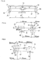
- this invention is adapted to an actuator which uses a ball screw and a ball nut as a screw and a feed nut.
- the actuator has a base 1 on which a ball screw 3 as the feed screw is mounted.
- the ball screw 3 has both ends rotatably supported by bearing members 5 and 7.
- the ball screw 3 is coupled via a coupling mechanism (not shown) to the output shaft of a servo motor 9 as a rotary driver.
- Engaged with the ball screw 3 is a ball nut 11 to which a slider 13 is attached.
- This slider 13 comprises a slider body 15 and a guide block 17 attached to this slider body 15.
- Laid on the base 1 is a rail 19 with which the guide block 17 is engaged in a movable fashion.
- the ball screw 3 rotates in the same direction.
- the ball nut 11 whose rotation is restricted moves in the proper direction.
- the slider 13 moves in the same direction.
- Support brackets 21 and 23 as support members are respectively provided on both sides of the slider 13.
- the support bracket 21 comprises a bracket body 25 and a guide block 27 attached to this bracket body 25.
- the ball screw 3 penetrates through the bracket body 25.
- the guide block 27 is movably engaged with the rail 19 on the base 1.
- a support bushing 29 is provided on that portion of the bracket body 25 where the ball screw 3 penetrates. This support bushing 29 has its inside diameter set slightly larger than the outside diameter of the ball screw 3.
- the support bracket 23 comprises a bracket body 31 and a guide block 33 attached to this bracket body 31.
- the ball screw 3 penetrates through the bracket body 31.
- the guide block 33 is movably engaged with the rail 19 on the base 1.
- a support bushing 35 is provided on that portion of the bracket body 31 where the ball screw 3 penetrates. This support bushing 35 has its inside diameter set slightly larger than the outside diameter of the ball screw 3.
- the support bracket 21 is located midway between the bearing member 5 and the slider 13.
- the support bracket 23 is likewise located midway between the bearing member 7 and the slider 13.
- a pulley 51 is rotatably attached as a rotary body to the bearing member 5, and a pulley 53 is likewise rotatably attached as a rotary body to the bearing member 7.
- a belt 55 as a thread member is put around the pulleys 51 and 53 and has its both ends respectively coupled to the bracket body 25 of the support bracket 21 and the bracket body 31 of the support bracket 23.
- the pulleys 51 and 53 and the belt 55 constitute the first coupling means.
- a pulley 57 as a rotary body is rotatably attached to the bracket body 25 of the support bracket 21.
- a pulley 59 as a rotary body is likewise rotatably attached to the bracket body 31 of the support bracket 23.
- a belt 61 as a thread member is put around the pulleys 57 and 59 and has its both ends coupled to the slider body 15 of the slider 13. The middle portion of the belt 61 is secured to the base 1.
- the fixing portion is indicated by reference numeral "62" in FIGS. 1 and 2.
- Available methods of securing the belt 61 to the base 1 include a way of fixing the belt 61 against the base 1 by means of an unillustrated metal fitting (with a stop screw to be fastened into the base 1) and a way of separating the belt 61 at the fixing portion and fixing the end portions of the separated portions of the belt 61 against the base 1 by means of metal fittings (with stop screws to be fastened into the base 1).
- the pulleys 57 and 59 and the belt 61 constitute the second coupling means.
- FIG. 2 exemplarily shows the structures of the pulleys 51, 53, 57 and 59 and the belts 55 and 61.
- the length of the belt 61 between the pulley 57 and the slider 13 becomes (L' - 50) mm, while the length of the belt 61 between the pulley 57 and the base 1 becomes (L' + 50) mm, as shown in FIG. 5. That is, the pulley 57 and the support bracket 21 have moved leftward in the diagram by 50 mm.
- This embodiment has the following advantages. First, the desired support performance can be attained without complicating the structure of the actuator or enlarging the actuator. This support performance can be accomplished simply by arranging the support brackets 21 and 23 on both sides of the slider 13 and coupling those support brackets 21 and 23 via the pulleys 51, 53, 57 and 59 and the belts 55 and 61.
- this embodiment needs no structure for retracting and protracting the intermediate support.
- the slider 13 is designed not to hit against the support brackets 21 and 23 to move them, and the support brackets 21 and 23 move at a half the acceleration/deceleration of the slider 13 in synchronism with acceleration/deceleration of the slider 13. Accordingly, the actuator operates smoothly and does not suffer any vibration and noise, which would have otherwise been produced by the impact of the fast-moving slider on the support members in the prior art.
- the support brackets 21 and 23 are so set as to be positioned respectively between the bearing member 5 and the slider 13 and between the bearing member 7 and the slider 13, while the slider 13 is positioned just midway between the bearing members 5 and 7.
- the support brackets are located at the position where their amplitudes would be large (B/2) if their middle portions were not supported. But, the shaft of the ball screw 3 is actually supported at that position, the primary vibration of the shaft is effectively suppressed so that the allowable number of rotations of the ball screw 3 can be increased.
- the first embodiment is so designed as to properly operate when the slider 13 and the support brackets 21 and 23 are in the range where the slider 13 does not contact the support brackets 21 and 23 and the support brackets 21 and 23 do not contact the bearing members 5 and 7. Let us consider this mechanism in the case where the slider 13 tries to advance further.
- the bearing members 5 and 7, the support brackets 21 and 23 and the slider 13 contact with one another simultaneously, the above situation can be avoided. While this phenomenon is geometrically possible, actually, it is hardly possible to cause such simultaneous contact.
- the original positions of the actuator may be detected by the mechanism which allows the slider 13 to be pressed against the bearing members 5 and 7 via the respective support brackets 21 and 23 at the respective ends in its movable range and detects the ends (the original positions of the actuator) as the slider 13 is stopped.
- the bearing members 5 and 7, the support brackets 21 and 23 and the slider 13 cannot be expected to contact with one another simultaneously, as mentioned above. Therefore, some tension inevitably acts on the belt 55.
- the moving range of the slider 13 should be restricted and the stopper blocks (not shown), for example, should be provided on the slider 13 and the base 1 to permit the use of the actuator within the range where the support brackets 21 and 23 do not contact the slider 13 and the bearing members 5 and 7.
- the second embodiment is designed in such a manner as to prevent the support brackets 21 and 23 from abutting on the bearing members 5 and 7 and the slider 13 and to prevent new tension to be applied on the belts 55 and 61.
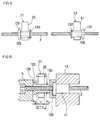
- support bushings 129 and 131 which are movable in the axial direction within a given range are provided in place of the support bushings 29 and 35 secured as feed screw supports to the support brackets 21 and 23 in the first embodiment, stopper rings 130 and 132 for restricting the moving ranges of the support bushings 129 and 131.
- the support bushings 129 and 131 are freely movable in the proper range (which differs depending on the size of the mechanism but is normally from several millimeters to about 10 mm) in the feeding direction to the support bracket bodies 25 and 31, and support the screw shaft.
- the support bushings 129 and 131 respectively have flanges 126 and 128.
- the support brackets 21 and 23 are coupled together by a rod member 71 as the first coupling means.
- a pulley 81 is attached to the bracket body 25 of the support bracket 21 and a pulley 83 is attached to the bracket body 31 of the support bracket 23.
- a belt 85 is put around those pulleys 81 and 83.
- This belt 85 has both ends coupled to the slider body 15 of the slider 13 and has its center portion secured to the base 1.
- the fixing portion is indicated by reference numeral "86" in FIGS. 11 and 12.
- the fixing method is the same as has already been explained in the section of the first embodiment.
- This embodiment can therefore have the same advantages as the first embodiment.
- this embodiment exhibits surer operational synchronization than the first embodiment.
- the support bushings 29 and 35 may be designed to be movable in the axial direction to prevent a new load from acting on the belt at the moving ends.
- the structure of the coupling means which comprises the first coupling means and second coupling means is not limited to those of the above-described embodiments.
- a ball screw is used as a feed screw and a ball nut is used as a feed nut in the individual embodiments
- the feed screw and feed nut should not necessarily be limited to the illustrated types.
- this invention is also effective when a square screw, a trapezoidal screw or the like is used. The same is true of the shape of the support members.
- the structure of the coupling means which comprises the first coupling means and second coupling means is not limited to that of the first and second embodiments; for example, sprockets and chains may be used in place of the pulleys and belts.
- the pulleys 51 and 53 as rotary bodies are respectively attached to a pair of bearing members 5 and 7 in the first and second embodiments, they may be attached to the base 1 or may be attached to another members (not shown) which are to be attached to the base 1.
Priority Applications (4)
| Application Number | Priority Date | Filing Date | Title |
|---|---|---|---|
| JP25892194A JP3221804B2 (ja) | 1994-09-28 | 1994-09-28 | アクチュエータ |
| DE1995621049 DE69521049T2 (de) | 1995-11-10 | 1995-11-10 | Linearantrieb mit Spindelabstützungen |
| EP95308066A EP0773389B1 (de) | 1994-09-28 | 1995-11-10 | Linearantrieb mit Spindelabstützungen |
| US08/558,263 US5720202A (en) | 1994-09-28 | 1995-11-13 | Actuator |
Applications Claiming Priority (3)
| Application Number | Priority Date | Filing Date | Title |
|---|---|---|---|
| JP25892194A JP3221804B2 (ja) | 1994-09-28 | 1994-09-28 | アクチュエータ |
| EP95308066A EP0773389B1 (de) | 1994-09-28 | 1995-11-10 | Linearantrieb mit Spindelabstützungen |
| US08/558,263 US5720202A (en) | 1994-09-28 | 1995-11-13 | Actuator |
Publications (2)
| Publication Number | Publication Date |
|---|---|
| EP0773389A1 true EP0773389A1 (de) | 1997-05-14 |
| EP0773389B1 EP0773389B1 (de) | 2001-05-23 |
Family
ID=27236916
Family Applications (1)
| Application Number | Title | Priority Date | Filing Date |
|---|---|---|---|
| EP95308066A Expired - Lifetime EP0773389B1 (de) | 1994-09-28 | 1995-11-10 | Linearantrieb mit Spindelabstützungen |
Country Status (3)
| Country | Link |
|---|---|
| US (1) | US5720202A (de) |
| EP (1) | EP0773389B1 (de) |
| JP (1) | JP3221804B2 (de) |
Cited By (4)
| Publication number | Priority date | Publication date | Assignee | Title |
|---|---|---|---|---|
| EP0828093A2 (de) * | 1996-09-06 | 1998-03-11 | Deutsche Star GmbH | Linearführungseinrichtung |
| WO2001039923A2 (de) * | 1999-11-30 | 2001-06-07 | HüLLER HILLE GMBH | Werkzeugmaschine, insbesondere langbett-werkzeugmaschine |
| EP2881621A3 (de) * | 2013-11-01 | 2016-09-14 | Yamaha Hatsudoki Kabushiki Kaisha | Aktuator |
| CN107035833A (zh) * | 2017-05-15 | 2017-08-11 | 浙江卓求传动科技有限公司 | 一种使用寿命长的滚珠丝杆及其制备方法 |
Families Citing this family (40)
| Publication number | Priority date | Publication date | Assignee | Title |
|---|---|---|---|---|
| DE19740208C2 (de) * | 1997-09-12 | 1999-07-22 | Fraunhofer Ges Forschung | Antriebsvorrichtung für mehrere Aggregate einer Drehmaschine |
| US6757056B1 (en) | 2001-03-26 | 2004-06-29 | Candela Instruments | Combined high speed optical profilometer and ellipsometer |
| US6031615A (en) | 1997-09-22 | 2000-02-29 | Candela Instruments | System and method for simultaneously measuring lubricant thickness and degradation, thin film thickness and wear, and surface roughness |
| US6392749B1 (en) | 1997-09-22 | 2002-05-21 | Candela Instruments | High speed optical profilometer for measuring surface height variation |
| JP2000088071A (ja) * | 1998-09-18 | 2000-03-28 | Smc Corp | 電動アクチュエータ |
| DE19926800A1 (de) * | 1999-06-11 | 2000-12-14 | Wittenstein Gmbh & Co Kg | Vorrichtung zum Steuern eines Triebwerkes |
| US6418807B2 (en) | 2000-03-06 | 2002-07-16 | Tol-O-Matic, Inc. | Stabilizer for ball screw actuator |
| US6899511B2 (en) | 2000-10-19 | 2005-05-31 | Rapid Development Services, Inc, Mo. Corp | Modular robotic device and manufacturing system |
| JP2004011681A (ja) * | 2002-06-04 | 2004-01-15 | Smc Corp | アクチュエータ |
| DE10322329A1 (de) * | 2003-05-17 | 2004-12-02 | Zf Lenksysteme Gmbh | Zugmittelgetriebe |
| DE102004055306B4 (de) * | 2003-11-21 | 2007-06-14 | Smc K.K. | Stellglied |
| US7684032B1 (en) | 2005-01-06 | 2010-03-23 | Kla-Tencor Corporation | Multi-wavelength system and method for detecting epitaxial layer defects |
| JP4886318B2 (ja) * | 2006-02-22 | 2012-02-29 | 株式会社アイエイアイ | アクチュエータ |
| JP5452630B2 (ja) | 2009-03-09 | 2014-03-26 | アリゾナ・ボード・オブ・リージェンツ,アクティング・フォー・アンド・オン・ビハーフ・オブ,ノーザン・アリゾナ・ユニバーシティ | 弾性モータばね作動装置 |
| JP5421844B2 (ja) * | 2010-04-22 | 2014-02-19 | ヤマハ発動機株式会社 | ボールねじ装置の駆動制御装置及び駆動制御方法 |
| CN101837554A (zh) * | 2010-05-19 | 2010-09-22 | 杭州机床集团有限公司 | 机床长丝杠牵引式随动支承装置 |
| JP5503014B2 (ja) * | 2010-10-08 | 2014-05-28 | 平田機工株式会社 | スライダ装置 |
| US9010205B2 (en) * | 2011-01-20 | 2015-04-21 | Pacific Bearing Company | Linear slide having integral carriage and nut assembly |
| CN102853050B (zh) * | 2011-06-29 | 2015-04-01 | 上银科技股份有限公司 | 长行程线性模组 |
| WO2013056727A1 (en) | 2011-10-17 | 2013-04-25 | Ntn-Snr Roulements | Drive screw system comprising slide bearing and slide bearing |
| EP2584223B1 (de) | 2011-10-17 | 2015-03-25 | NTN-SNR Roulements | Gewindespindelantrieb mit Gleitführung und Gleitführung |
| CN103252678B (zh) * | 2012-08-31 | 2016-01-13 | 天津市天工伟业数控机床有限公司 | 滚珠丝杆防晃装置 |
| JP2015055273A (ja) * | 2013-09-11 | 2015-03-23 | 株式会社アイエイアイ | アクチュエータ |
| JP6247588B2 (ja) * | 2013-11-01 | 2017-12-13 | ヤマハ発動機株式会社 | アクチュエーター |
| TWI524018B (zh) * | 2013-11-28 | 2016-03-01 | 上銀科技股份有限公司 | 具有支撐裝置的滾珠螺桿 |
| CN104728379B (zh) * | 2013-12-18 | 2017-05-10 | 上银科技股份有限公司 | 滚珠螺杆支撑装置 |
| DE102014101246B4 (de) | 2014-02-02 | 2015-08-20 | Hiwin Technologies Corp. | Mit einem Stützwerk versehene Kugelrollspindel |
| KR101512763B1 (ko) * | 2014-02-19 | 2015-04-16 | 히윈 테크놀러지스 코포레이션 | 볼 스크류용 지지 구조체 |
| DE102014109561B3 (de) * | 2014-07-08 | 2015-09-10 | Hiwin Technologies Corp. | Linearmodul mit einer Stützvorrichtung |
| US9285021B2 (en) | 2014-07-22 | 2016-03-15 | Hiwin Technologies Corp. | Linear module with a support device |
| JP2016114177A (ja) * | 2014-12-16 | 2016-06-23 | 上銀科技股▲分▼有限公司 | ボールねじ |
| CN106246844B (zh) * | 2016-08-09 | 2019-06-11 | 中国科学院长春光学精密机械与物理研究所 | 光栅刻划机及其螺母减重装置 |
| CN106499785A (zh) * | 2016-10-28 | 2017-03-15 | 成都福誉科技有限公司 | 一种高精度直线模组及其控制方法 |
| TWI615236B (zh) * | 2016-12-13 | 2018-02-21 | Hiwin Tech Corp | 具有模組化支撐裝置之線性傳動機構 |
| JP1587328S (de) * | 2017-02-15 | 2017-10-02 | ||
| DE102017103728B3 (de) | 2017-02-23 | 2018-03-22 | Hiwin Technologies Corp. | Linearantrieb mit modularer Stützvorrichtung |
| CN108050218A (zh) * | 2018-01-29 | 2018-05-18 | 潍坊海丰自动化科技有限公司 | 直线驱动装置及直线运动设备 |
| JP1614110S (de) * | 2018-04-04 | 2018-09-25 | ||
| US11598400B2 (en) | 2020-11-19 | 2023-03-07 | Pacific Bearing Corporation | Nut with flexible fingers and self-aligning members |
| CN114770188A (zh) * | 2022-04-22 | 2022-07-22 | 北京烁科精微电子装备有限公司 | 一种传动支架以及滑移装置 |
Citations (5)
| Publication number | Priority date | Publication date | Assignee | Title |
|---|---|---|---|---|
| US3010328A (en) * | 1958-02-18 | 1961-11-28 | Lip Sa | Device for remote-controlling movable mechanical members through transmission means of the reversible motion type |
| DE1961441A1 (de) * | 1969-12-08 | 1971-06-24 | Wanderer Werke Ag | Einrichtung zur Abstuetzung langer Gewindespindeln |
| JPH01247862A (ja) | 1988-02-11 | 1989-10-03 | Neff Gewindespindeln Gmbh | 線形位置決め装置 |
| JPH0272254A (ja) * | 1988-09-07 | 1990-03-12 | Nippon Seiko Kk | 送りねじ支持装置 |
| DE4335092A1 (de) | 1992-10-14 | 1994-04-21 | Nsk Ltd | Vorschubvorrichtung für ein bewegliches Teil |
Family Cites Families (4)
| Publication number | Priority date | Publication date | Assignee | Title |
|---|---|---|---|---|
| CH519125A (de) * | 1970-01-16 | 1972-02-15 | Haller Richard | Vorrichtung zur gegenseitigen axialen Verschiebung einer Welle oder Gewindespindel oder Zahnstange einerseits und eines darauf angeordneten Elementes anderseits |
| JP2867386B2 (ja) * | 1988-08-31 | 1999-03-08 | 日本精工株式会社 | 送りねじ支持装置 |
| JP2567800Y2 (ja) * | 1991-09-30 | 1998-04-02 | 日本精工株式会社 | ねじ軸用中間サポート装置 |
| US5531557A (en) * | 1994-07-01 | 1996-07-02 | Rite-Hite Corporation | Drive screw system with nested mobile supports |
-
1994
- 1994-09-28 JP JP25892194A patent/JP3221804B2/ja not_active Expired - Fee Related
-
1995
- 1995-11-10 EP EP95308066A patent/EP0773389B1/de not_active Expired - Lifetime
- 1995-11-13 US US08/558,263 patent/US5720202A/en not_active Expired - Lifetime
Patent Citations (5)
| Publication number | Priority date | Publication date | Assignee | Title |
|---|---|---|---|---|
| US3010328A (en) * | 1958-02-18 | 1961-11-28 | Lip Sa | Device for remote-controlling movable mechanical members through transmission means of the reversible motion type |
| DE1961441A1 (de) * | 1969-12-08 | 1971-06-24 | Wanderer Werke Ag | Einrichtung zur Abstuetzung langer Gewindespindeln |
| JPH01247862A (ja) | 1988-02-11 | 1989-10-03 | Neff Gewindespindeln Gmbh | 線形位置決め装置 |
| JPH0272254A (ja) * | 1988-09-07 | 1990-03-12 | Nippon Seiko Kk | 送りねじ支持装置 |
| DE4335092A1 (de) | 1992-10-14 | 1994-04-21 | Nsk Ltd | Vorschubvorrichtung für ein bewegliches Teil |
Non-Patent Citations (1)
| Title |
|---|
| PATENT ABSTRACTS OF JAPAN vol. 014, no. 256 (M - 0980) 4 June 1990 (1990-06-04) * |
Cited By (8)
| Publication number | Priority date | Publication date | Assignee | Title |
|---|---|---|---|---|
| EP0828093A2 (de) * | 1996-09-06 | 1998-03-11 | Deutsche Star GmbH | Linearführungseinrichtung |
| EP0828093A3 (de) * | 1996-09-06 | 1998-07-01 | Deutsche Star GmbH | Linearführungseinrichtung |
| US5974904A (en) * | 1996-09-06 | 1999-11-02 | Deutsche Star Gmbh | Linear guide device |
| WO2001039923A2 (de) * | 1999-11-30 | 2001-06-07 | HüLLER HILLE GMBH | Werkzeugmaschine, insbesondere langbett-werkzeugmaschine |
| WO2001039923A3 (de) * | 1999-11-30 | 2004-02-19 | Hueller Hille Gmbh | Werkzeugmaschine, insbesondere langbett-werkzeugmaschine |
| EP2881621A3 (de) * | 2013-11-01 | 2016-09-14 | Yamaha Hatsudoki Kabushiki Kaisha | Aktuator |
| US9752664B2 (en) | 2013-11-01 | 2017-09-05 | Yamaha Hatsudoki Kabushiki Kaisha | Actuator |
| CN107035833A (zh) * | 2017-05-15 | 2017-08-11 | 浙江卓求传动科技有限公司 | 一种使用寿命长的滚珠丝杆及其制备方法 |
Also Published As
| Publication number | Publication date |
|---|---|
| JP3221804B2 (ja) | 2001-10-22 |
| EP0773389B1 (de) | 2001-05-23 |
| JPH0898455A (ja) | 1996-04-12 |
| US5720202A (en) | 1998-02-24 |
Similar Documents
| Publication | Publication Date | Title |
|---|---|---|
| EP0773389A1 (de) | Linearantrieb mit Spindelabstützungen | |
| US5587637A (en) | Robot arm device capable of conveying an article in circumferential and radial directions | |
| TW432774B (en) | Actuator | |
| US5140863A (en) | Screw-nut feed mechanism | |
| EP0385313B1 (de) | Vorrichtung zur Luftspalteinrichtung eines linearen Ringmotors | |
| US6033330A (en) | Belt noise/vibration control mechanism | |
| JP2923951B2 (ja) | 送りねじ支持装置 | |
| US20010025534A1 (en) | Stabilizer for ball screw actuator | |
| KR100924398B1 (ko) | 각도 조정 장치 | |
| KR100403003B1 (ko) | 액튜에이터 | |
| JPH04121337A (ja) | ベルト駆動装置 | |
| EP0602648A1 (de) | Durch Vibrationen angetreibener Motor oder Antrieb | |
| JP2827716B2 (ja) | ボールねじ装置 | |
| JPH1034587A (ja) | 工業用ロボット | |
| JP3772315B2 (ja) | 圧電ユニット及びそれを用いた移動テーブル | |
| JP2002130419A (ja) | アクチュエータ | |
| JP3384438B2 (ja) | 直線動作装置 | |
| JP2570672B2 (ja) | 微小回転装置 | |
| KR0133694Y1 (ko) | 직동 배속 장치 | |
| JPH07293659A (ja) | ボールねじ装置 | |
| JPH04133928A (ja) | ベルト駆動装置 | |
| JPH0544801A (ja) | ベルト駆動装置 | |
| JP2599373Y2 (ja) | 直線作動ユニット | |
| JPH03196991A (ja) | ロボット | |
| JP2003065331A (ja) | アクチュエータ |
Legal Events
| Date | Code | Title | Description |
|---|---|---|---|
| PUAI | Public reference made under article 153(3) epc to a published international application that has entered the european phase |
Free format text: ORIGINAL CODE: 0009012 |
|
| AK | Designated contracting states |
Kind code of ref document: A1 Designated state(s): DE FR GB IT |
|
| 17P | Request for examination filed |
Effective date: 19971031 |
|
| 17Q | First examination report despatched |
Effective date: 19990503 |
|
| GRAG | Despatch of communication of intention to grant |
Free format text: ORIGINAL CODE: EPIDOS AGRA |
|
| GRAG | Despatch of communication of intention to grant |
Free format text: ORIGINAL CODE: EPIDOS AGRA |
|
| GRAH | Despatch of communication of intention to grant a patent |
Free format text: ORIGINAL CODE: EPIDOS IGRA |
|
| GRAH | Despatch of communication of intention to grant a patent |
Free format text: ORIGINAL CODE: EPIDOS IGRA |
|
| GRAA | (expected) grant |
Free format text: ORIGINAL CODE: 0009210 |
|
| AK | Designated contracting states |
Kind code of ref document: B1 Designated state(s): DE FR GB IT |
|
| ITF | It: translation for a ep patent filed |
Owner name: BUZZI, NOTARO&ANTONIELLI D'OULX |
|
| REF | Corresponds to: |
Ref document number: 69521049 Country of ref document: DE Date of ref document: 20010628 |
|
| ET | Fr: translation filed | ||
| REG | Reference to a national code |
Ref country code: GB Ref legal event code: IF02 |
|
| PLBE | No opposition filed within time limit |
Free format text: ORIGINAL CODE: 0009261 |
|
| STAA | Information on the status of an ep patent application or granted ep patent |
Free format text: STATUS: NO OPPOSITION FILED WITHIN TIME LIMIT |
|
| 26N | No opposition filed | ||
| PGFP | Annual fee paid to national office [announced via postgrant information from national office to epo] |
Ref country code: DE Payment date: 20081107 Year of fee payment: 14 |
|
| PGFP | Annual fee paid to national office [announced via postgrant information from national office to epo] |
Ref country code: IT Payment date: 20081126 Year of fee payment: 14 |
|
| PGFP | Annual fee paid to national office [announced via postgrant information from national office to epo] |
Ref country code: FR Payment date: 20081112 Year of fee payment: 14 |
|
| PGFP | Annual fee paid to national office [announced via postgrant information from national office to epo] |
Ref country code: GB Payment date: 20081105 Year of fee payment: 14 |
|
| GBPC | Gb: european patent ceased through non-payment of renewal fee |
Effective date: 20091110 |
|
| REG | Reference to a national code |
Ref country code: FR Ref legal event code: ST Effective date: 20100730 |
|
| PG25 | Lapsed in a contracting state [announced via postgrant information from national office to epo] |
Ref country code: FR Free format text: LAPSE BECAUSE OF NON-PAYMENT OF DUE FEES Effective date: 20091130 |
|
| PG25 | Lapsed in a contracting state [announced via postgrant information from national office to epo] |
Ref country code: DE Free format text: LAPSE BECAUSE OF NON-PAYMENT OF DUE FEES Effective date: 20100601 |
|
| PG25 | Lapsed in a contracting state [announced via postgrant information from national office to epo] |
Ref country code: GB Free format text: LAPSE BECAUSE OF NON-PAYMENT OF DUE FEES Effective date: 20091110 |
|
| PG25 | Lapsed in a contracting state [announced via postgrant information from national office to epo] |
Ref country code: IT Free format text: LAPSE BECAUSE OF NON-PAYMENT OF DUE FEES Effective date: 20091110 |