US6033330A - Belt noise/vibration control mechanism - Google Patents
Belt noise/vibration control mechanism Download PDFInfo
- Publication number
- US6033330A US6033330A US08/477,963 US47796395A US6033330A US 6033330 A US6033330 A US 6033330A US 47796395 A US47796395 A US 47796395A US 6033330 A US6033330 A US 6033330A
- Authority
- US
- United States
- Prior art keywords
- belt
- idler
- noise
- damping
- arm
- Prior art date
- Legal status (The legal status is an assumption and is not a legal conclusion. Google has not performed a legal analysis and makes no representation as to the accuracy of the status listed.)
- Expired - Fee Related
Links
- 230000007246 mechanism Effects 0.000 title description 8
- 239000004677 Nylon Substances 0.000 claims description 3
- 229920001778 nylon Polymers 0.000 claims description 3
- 238000013016 damping Methods 0.000 abstract description 31
- 239000000463 material Substances 0.000 description 10
- 238000012360 testing method Methods 0.000 description 5
- 230000008901 benefit Effects 0.000 description 2
- 230000006872 improvement Effects 0.000 description 2
- 238000000034 method Methods 0.000 description 2
- 239000007787 solid Substances 0.000 description 2
- 238000013461 design Methods 0.000 description 1
- 238000002474 experimental method Methods 0.000 description 1
- 239000002085 irritant Substances 0.000 description 1
- 231100000021 irritant Toxicity 0.000 description 1
- 238000012986 modification Methods 0.000 description 1
- 230000004048 modification Effects 0.000 description 1
- 238000000465 moulding Methods 0.000 description 1
- 108091008695 photoreceptors Proteins 0.000 description 1
- 239000004033 plastic Substances 0.000 description 1
- 230000008569 process Effects 0.000 description 1
- 230000000644 propagated effect Effects 0.000 description 1
- 230000009467 reduction Effects 0.000 description 1
- 239000000126 substance Substances 0.000 description 1
Images

Classifications
-
- F—MECHANICAL ENGINEERING; LIGHTING; HEATING; WEAPONS; BLASTING
- F16—ENGINEERING ELEMENTS AND UNITS; GENERAL MEASURES FOR PRODUCING AND MAINTAINING EFFECTIVE FUNCTIONING OF MACHINES OR INSTALLATIONS; THERMAL INSULATION IN GENERAL
- F16F—SPRINGS; SHOCK-ABSORBERS; MEANS FOR DAMPING VIBRATION
- F16F15/00—Suppression of vibrations in systems; Means or arrangements for avoiding or reducing out-of-balance forces, e.g. due to motion
- F16F15/02—Suppression of vibrations of non-rotating, e.g. reciprocating systems; Suppression of vibrations of rotating systems by use of members not moving with the rotating systems
- F16F15/022—Suppression of vibrations of non-rotating, e.g. reciprocating systems; Suppression of vibrations of rotating systems by use of members not moving with the rotating systems using dampers and springs in combination
-
- F—MECHANICAL ENGINEERING; LIGHTING; HEATING; WEAPONS; BLASTING
- F16—ENGINEERING ELEMENTS AND UNITS; GENERAL MEASURES FOR PRODUCING AND MAINTAINING EFFECTIVE FUNCTIONING OF MACHINES OR INSTALLATIONS; THERMAL INSULATION IN GENERAL
- F16H—GEARING
- F16H7/00—Gearings for conveying rotary motion by endless flexible members
- F16H7/08—Means for varying tension of belts, ropes, or chains
- F16H7/10—Means for varying tension of belts, ropes, or chains by adjusting the axis of a pulley
- F16H7/12—Means for varying tension of belts, ropes, or chains by adjusting the axis of a pulley of an idle pulley
- F16H7/1209—Means for varying tension of belts, ropes, or chains by adjusting the axis of a pulley of an idle pulley with vibration damping means
-
- F—MECHANICAL ENGINEERING; LIGHTING; HEATING; WEAPONS; BLASTING
- F16—ENGINEERING ELEMENTS AND UNITS; GENERAL MEASURES FOR PRODUCING AND MAINTAINING EFFECTIVE FUNCTIONING OF MACHINES OR INSTALLATIONS; THERMAL INSULATION IN GENERAL
- F16H—GEARING
- F16H7/00—Gearings for conveying rotary motion by endless flexible members
- F16H7/08—Means for varying tension of belts, ropes, or chains
- F16H2007/0889—Path of movement of the finally actuated member
- F16H2007/0893—Circular path
Definitions
- This invention relates to a belt noise control mechanism for use in a wide variety of machines, for example, copier/printers.
- Noise and vibration problems are caused by tolerance build up and variations in materials among the moving parts. To name some of them, they are as follows: non-concentric of the drive shafts, non-concentric of the pulley, variations in the teeth of the pulleys and imperfections in the belts. Imperfections in the belts may include waviness at the back of the belt, variations in belt thickness due to a seam, variations in belt thickness due to molding process or variations in the belt teeth. As a result, this will induce random motion to the belt tensioning device. Excessive noise and vibration will be generated and transmitted to the frame of the machine through the belt tensioning device.
- Previous belt drive systems include U.S. Pat. No. 2,913,192 which is directed to a tape drive mechanism for driving tapes under constant tension and speed.
- a resilient flexing spring bent into a curve allows the tape to travel accurately to a recording head. The spring permits compliance in one direction and appears to be suitable for only light tension applications.
- a multi-lever and multi-spring system to slow down a portion of a belt temporarily while keeping the rest of the belt at a different speed is disclosed in U.S. Pat. No. 4,869,707.
- a locking assembly for a photoreceptor belt is shown in U.S. Pat. No. 4,983,146 in which a spring is used to provide an initial tension and the assembly is locked down by a locking arm. After the locking mechanism is engaged, the spring is not functioning.
- U.S. Pat. No. 4,459,123 discloses the arrangement of a single or multiple belt system for maximum drive efficiency. The drive machinery that requires the most torque is located closest to the driving unit. Additional drive units are placed in descending order according to the magnitudes of the drive torques.
- German Patent 2,902,182 discloses a three piece coil strip used to tension a V-belt on a motor vehicle engine. In view of these patents, a need clearly still exists for a means to control noise in machines.
- an apparatus that includes an element that supports an idler, damps acoustic waves, controls the position of the idler, which controls a belt and dissipates acoustic waves to thereby diminish noise and vibration in a belt drive system.
- the apparatus includes a damping element connected to an idler and appropriate mounting structure.
- the damping element which can be tuned dissipates and/or isolates the source of noise and/or vibration energy that would otherwise be generated, transmitted, propagated and amplified throughout the belt drive system.
- FIG. 1 is a graph showing test results according to a prior art belt drive system.
- FIG. 2 is a schematic view illustrating a belt drive system utilizing a damping idler arm in accordance with the present invention.
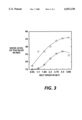
- FIG. 3 is a graph showing the test results obtained from testing the apparatus of FIG. 2.
- the graph in FIG. 1 shows noise level of an idler vis-a-vis that of a belt and pulley with the noise level of the idler being much higher than that of both the belt and pulley. Even at low speeds, the noise level of the idler is higher than that of belt and pulley combined.
- the torque applied was 0.1N-M
- the noise level of the belt and pulley is represented by O.
- FIG. 2 that comprises an idler system with tuned damping capability.
- damping is used herein to mean the dissipation of vibratory/acoustic energy in a system. This is usually achieved by means of viscous or viscoelastic behavior which can be found in some plastic materials.
- a single endless timing belt 12 is shown, which transmits drive power from a drive pulley 14, which in turn drives idler pulley 16.
- An idler 20 is biased against timing belt 12 in an unsupported span between pulleys 14 and 16 by a singgle piece and homogenous idler arm 22 with tuned damping that is made of materials with a relatively high damping coefficient, such as, Nylon. Materials other than Nylon having damping coeffients up to 2.0 could be used for damping purposes, if desired.
- the decision as to which material to use should be based on the predetermined magnitudes and dominant frequencies of the vibrations coming from the belt system. The unwanted noise/vibration coming from the belt system is dissipated due to the damping materials. This controls the motion of the idler/belt.
- the idler arm it can be configured as disclosed in FIG.
- Idler arm 22 is supported for pivoted movement on support shaft/pin 26.
- a hard stop 24 is included to control maximum positioning of idler arm 22. Any hard stop means could be used, for example, they can be built into support 26 by use of a "D" hole.
- Idler arm 22 can be of any desired configuration as long as it provides support for the idler roll 20 and maintains tension for the belt. This system attenuates the undesirable vibrating energy and reduces noise.
- an additional benefit of the idler noise control configuration in FIG. 2 is that the physical, chemical and mechanical properties including the materials of the tuned damping element can be optimized to provide active damping to attenuate the vibration of the belt system. With tuned damping, control of noise and vibration is enabled.
- traditional idler systems consist of a rigid support arm and a spring which may be a wrap spring or an extension spring. While a tuned damping arm 22 is shown in FIG. 2, an arm with damping material can be used to obtain some reduction in noise and vibration, but with less results than a tuned damping arm.
- Tuned damping is used herein to mean a method and apparatus for controlling vibration/noise of a belt system. Assuming one has two systems as here including the belt system and the arm control mechanism, the belt system consists of the belt and two pulleys and the arm control mechanism consists of the arm, idler and the mountings. Tune damping is achieved by first predetermining the magnitude and the dominant frequencies'of the noise and vibration coming from the belt system. Then the arm control mechanism is designed by experiment for optimum control by means of optimum stiffness and damping. This can be achieved by choosing the length, width and thickness of the arm, selecting the proper system mass, as well as, the materials with the proper elastic modulus and damping coefficient.
- the system of FIG. 2 was tested with different idler configurations, such as, straight crown, solid, spoke and idlers with sleeves, etc. and they all showed marketed noise abatement improvement over existing design configurations.
- the test results shown in FIG. 3 were obtained using a solid idler having an outside diameter of 20 mm and a width of 13 mm. With this idler, a noise improvement of up to 12 dBA (i.e. 97%) was obtained.
- the upper curve and the lower curve in the figure represent the noise levels of an existing system and the tune damping system, respectively.
- the center of support shaft to center of idler length of tuned damping arm 22 was 56 mm and center of hard stop to center of idler distance was 44 mm for the test.
- the system tested included idler arm 22 made of a material with a relatively high damping coefficient and having a pin or shaft extending orthogonally from an end thereof remote from shaft 26.
- An idler roll 20 was loosely mounted on the pin such that it could move to some extent laterally and vertically with results as shown in FIG. 1. Mounting of the idler roll on the pin of the idler roll could be in many conventional forms, for example, ball bearing could be used.
- noise abatement is attained by including a tuned damping element attached to idlers operating on timing belts.
- This control mechanism reduces noise by providing the support and resiliency required for the idler operation.
- the tuned damping element is usable with roll systems, as well as, belt and drive systems.
- Belt and drive systems include, but are not limited to, flat belts, timing belts, V-belts, chain drives and some gear drives. It is also applicable to all tensioning devices.
- An advantage of the tuned damping element is that it allows self alignment at the point(s) of application(s).
Landscapes
- Engineering & Computer Science (AREA)
- General Engineering & Computer Science (AREA)
- Mechanical Engineering (AREA)
- Physics & Mathematics (AREA)
- Acoustics & Sound (AREA)
- Aviation & Aerospace Engineering (AREA)
- Devices For Conveying Motion By Means Of Endless Flexible Members (AREA)
Abstract
Description
Claims (1)
Priority Applications (1)
| Application Number | Priority Date | Filing Date | Title |
|---|---|---|---|
| US08/477,963 US6033330A (en) | 1991-06-27 | 1995-06-07 | Belt noise/vibration control mechanism |
Applications Claiming Priority (3)
| Application Number | Priority Date | Filing Date | Title |
|---|---|---|---|
| US72273491A | 1991-06-27 | 1991-06-27 | |
| US19674194A | 1994-02-15 | 1994-02-15 | |
| US08/477,963 US6033330A (en) | 1991-06-27 | 1995-06-07 | Belt noise/vibration control mechanism |
Related Parent Applications (1)
| Application Number | Title | Priority Date | Filing Date |
|---|---|---|---|
| US19674194A Continuation-In-Part | 1991-06-27 | 1994-02-15 |
Publications (1)
| Publication Number | Publication Date |
|---|---|
| US6033330A true US6033330A (en) | 2000-03-07 |
Family
ID=26892185
Family Applications (1)
| Application Number | Title | Priority Date | Filing Date |
|---|---|---|---|
| US08/477,963 Expired - Fee Related US6033330A (en) | 1991-06-27 | 1995-06-07 | Belt noise/vibration control mechanism |
Country Status (1)
| Country | Link |
|---|---|
| US (1) | US6033330A (en) |
Cited By (15)
| Publication number | Priority date | Publication date | Assignee | Title |
|---|---|---|---|---|
| US20040134176A1 (en) * | 2002-10-14 | 2004-07-15 | Mtd Products Inc: | Vibration damping assembly |
| FR2862735A1 (en) * | 2003-11-25 | 2005-05-27 | Sagem | Flat scanner device for producing digital document, has belt idler device with flexible arm bent in horizontal plane, and pin spring with two branches situated on both sides of pulley supported by vertical axle |
| US20070155557A1 (en) * | 2005-12-30 | 2007-07-05 | Horst Robert W | Deflector assembly |
| US20070254757A1 (en) * | 2006-04-26 | 2007-11-01 | Leao Wang | Compression roller for an exercise apparatus with a crank transmission unit |
| US20080195005A1 (en) * | 2007-02-14 | 2008-08-14 | Horst Robert W | Methods and devices for deep vein thrombosis prevention |
| US20090131208A1 (en) * | 2005-04-08 | 2009-05-21 | Hawryluck Chris D | Tensioner With Molded Arm |
| US20090204038A1 (en) * | 2008-02-08 | 2009-08-13 | Tibion Corporation | Multi-fit orthotic and mobility assistance apparatus |
| US20090306548A1 (en) * | 2008-06-05 | 2009-12-10 | Bhugra Kern S | Therapeutic method and device for rehabilitation |
| US20100038983A1 (en) * | 2008-08-14 | 2010-02-18 | Kern Bhugra | Actuator system with a motor assembly and latch for extending and flexing a joint |
| US20100039052A1 (en) * | 2008-08-14 | 2010-02-18 | Horst Robert W | Actuator system with a multi-motor assembly for extending and flexing a joint |
| US20100204620A1 (en) * | 2009-02-09 | 2010-08-12 | Smith Jonathan A | Therapy and mobility assistance system |
| US20100318006A1 (en) * | 2002-11-25 | 2010-12-16 | Horst Robert W | Power regeneration in active muscle assistance device and method |
| US8639455B2 (en) | 2009-02-09 | 2014-01-28 | Alterg, Inc. | Foot pad device and method of obtaining weight data |
| US9889058B2 (en) | 2013-03-15 | 2018-02-13 | Alterg, Inc. | Orthotic device drive system and method |
| US11131367B2 (en) * | 2017-12-04 | 2021-09-28 | Kmc Chain Industrial Co., Ltd. | Chain tensioning device |
Citations (18)
| Publication number | Priority date | Publication date | Assignee | Title |
|---|---|---|---|---|
| US1286482A (en) * | 1917-08-25 | 1918-12-03 | Isidor A Schulherr | Belt-tightener. |
| US1513473A (en) * | 1923-06-04 | 1924-10-28 | Curtis & Company Mfg Company | Automatic belt tightener |
| US1847720A (en) * | 1928-09-10 | 1932-03-01 | Marcellis Carmen Wood | Spring belt tension adjuster |
| US2549038A (en) * | 1946-08-16 | 1951-04-17 | Armour Res Found | Winding and reeling mechanism |
| FR1081876A (en) * | 1953-05-07 | 1954-12-23 | Device to catch the elongation of belts | |
| US2913192A (en) * | 1956-09-07 | 1959-11-17 | Minnesota Mining & Mfg | Tape drive mechanism |
| FR1346804A (en) * | 1963-02-11 | 1963-12-20 | Plastic chain tensioners with fixed or articulated semi-elastic arm, for cycles, tandems, mopeds, motorcycles | |
| US3490302A (en) * | 1967-05-31 | 1970-01-20 | Borg Warner | Chain tensioner |
| US3636786A (en) * | 1970-09-03 | 1972-01-25 | Fedders Corp | Drive adjustment for fixed center drive |
| DE2902182A1 (en) * | 1979-01-20 | 1980-07-24 | Boge Gmbh | TURN-ELASTIC BEARING EQUIPPED WITH AN ELASTOMER BODY, IN PARTICULAR FOR V-BELT TENSIONERS OF MOTOR VEHICLE ENGINES |
| GB2056014A (en) * | 1979-08-07 | 1981-03-11 | Skf Kugellagerfabriken Gmbh | Guide Roll Arrangement for a Tangential Drive Belt of a Spinning Machine |
| US4459123A (en) * | 1981-02-28 | 1984-07-10 | Nippon Soken, Inc. | Driving method for auxiliary machinery of a vehicle |
| US4525152A (en) * | 1982-07-27 | 1985-06-25 | Dayco Corporation | Belt tensioner and method of making the same |
| US4869707A (en) * | 1987-12-07 | 1989-09-26 | Oce-Nederland B.V. | Belt tension device |
| US4908006A (en) * | 1987-09-02 | 1990-03-13 | Vyzkumny Ustav Bavlnarsky | Belt tightening device for open-end spinning machines |
| US4908007A (en) * | 1988-11-23 | 1990-03-13 | Dayco Products, Inc. | Belt tensioner and method of making the same |
| US4983146A (en) * | 1987-03-23 | 1991-01-08 | Colorocs Corporation | Belt tensioning and quick release device for electrophotographic system |
| US5176580A (en) * | 1990-10-16 | 1993-01-05 | Caoutchouc Manufacture Et Plastiques | Belt tensioner for internal combustion engine |
-
1995
- 1995-06-07 US US08/477,963 patent/US6033330A/en not_active Expired - Fee Related
Patent Citations (18)
| Publication number | Priority date | Publication date | Assignee | Title |
|---|---|---|---|---|
| US1286482A (en) * | 1917-08-25 | 1918-12-03 | Isidor A Schulherr | Belt-tightener. |
| US1513473A (en) * | 1923-06-04 | 1924-10-28 | Curtis & Company Mfg Company | Automatic belt tightener |
| US1847720A (en) * | 1928-09-10 | 1932-03-01 | Marcellis Carmen Wood | Spring belt tension adjuster |
| US2549038A (en) * | 1946-08-16 | 1951-04-17 | Armour Res Found | Winding and reeling mechanism |
| FR1081876A (en) * | 1953-05-07 | 1954-12-23 | Device to catch the elongation of belts | |
| US2913192A (en) * | 1956-09-07 | 1959-11-17 | Minnesota Mining & Mfg | Tape drive mechanism |
| FR1346804A (en) * | 1963-02-11 | 1963-12-20 | Plastic chain tensioners with fixed or articulated semi-elastic arm, for cycles, tandems, mopeds, motorcycles | |
| US3490302A (en) * | 1967-05-31 | 1970-01-20 | Borg Warner | Chain tensioner |
| US3636786A (en) * | 1970-09-03 | 1972-01-25 | Fedders Corp | Drive adjustment for fixed center drive |
| DE2902182A1 (en) * | 1979-01-20 | 1980-07-24 | Boge Gmbh | TURN-ELASTIC BEARING EQUIPPED WITH AN ELASTOMER BODY, IN PARTICULAR FOR V-BELT TENSIONERS OF MOTOR VEHICLE ENGINES |
| GB2056014A (en) * | 1979-08-07 | 1981-03-11 | Skf Kugellagerfabriken Gmbh | Guide Roll Arrangement for a Tangential Drive Belt of a Spinning Machine |
| US4459123A (en) * | 1981-02-28 | 1984-07-10 | Nippon Soken, Inc. | Driving method for auxiliary machinery of a vehicle |
| US4525152A (en) * | 1982-07-27 | 1985-06-25 | Dayco Corporation | Belt tensioner and method of making the same |
| US4983146A (en) * | 1987-03-23 | 1991-01-08 | Colorocs Corporation | Belt tensioning and quick release device for electrophotographic system |
| US4908006A (en) * | 1987-09-02 | 1990-03-13 | Vyzkumny Ustav Bavlnarsky | Belt tightening device for open-end spinning machines |
| US4869707A (en) * | 1987-12-07 | 1989-09-26 | Oce-Nederland B.V. | Belt tension device |
| US4908007A (en) * | 1988-11-23 | 1990-03-13 | Dayco Products, Inc. | Belt tensioner and method of making the same |
| US5176580A (en) * | 1990-10-16 | 1993-01-05 | Caoutchouc Manufacture Et Plastiques | Belt tensioner for internal combustion engine |
Non-Patent Citations (1)
| Title |
|---|
| Vibration Damping by Ahid D. Nashif et al., Distributed by John Wiley & Sons, Inc., New York, NY 1985, Chapter 5, pp. 189 Through 215. * |
Cited By (28)
| Publication number | Priority date | Publication date | Assignee | Title |
|---|---|---|---|---|
| US20040134176A1 (en) * | 2002-10-14 | 2004-07-15 | Mtd Products Inc: | Vibration damping assembly |
| US6931825B2 (en) | 2002-10-14 | 2005-08-23 | Terry J. Stineman | Vibration damping assembly |
| US20100318006A1 (en) * | 2002-11-25 | 2010-12-16 | Horst Robert W | Power regeneration in active muscle assistance device and method |
| US8679040B2 (en) | 2002-11-25 | 2014-03-25 | Alterg, Inc. | Intention-based therapy device and method |
| FR2862735A1 (en) * | 2003-11-25 | 2005-05-27 | Sagem | Flat scanner device for producing digital document, has belt idler device with flexible arm bent in horizontal plane, and pin spring with two branches situated on both sides of pulley supported by vertical axle |
| EP1536159A3 (en) * | 2003-11-25 | 2010-02-10 | Sagem Communications Sas | Flat bed scanner with belt and belt tensioning device |
| US20090131208A1 (en) * | 2005-04-08 | 2009-05-21 | Hawryluck Chris D | Tensioner With Molded Arm |
| US7811189B2 (en) * | 2005-12-30 | 2010-10-12 | Tibion Corporation | Deflector assembly |
| US20070155557A1 (en) * | 2005-12-30 | 2007-07-05 | Horst Robert W | Deflector assembly |
| US20070254757A1 (en) * | 2006-04-26 | 2007-11-01 | Leao Wang | Compression roller for an exercise apparatus with a crank transmission unit |
| US9474673B2 (en) | 2007-02-14 | 2016-10-25 | Alterg, Inc. | Methods and devices for deep vein thrombosis prevention |
| US20080195005A1 (en) * | 2007-02-14 | 2008-08-14 | Horst Robert W | Methods and devices for deep vein thrombosis prevention |
| US8353854B2 (en) | 2007-02-14 | 2013-01-15 | Tibion Corporation | Method and devices for moving a body joint |
| US20090204038A1 (en) * | 2008-02-08 | 2009-08-13 | Tibion Corporation | Multi-fit orthotic and mobility assistance apparatus |
| US8771210B2 (en) | 2008-02-08 | 2014-07-08 | Alterg, Inc. | Multi-fit orthotic and mobility assistance apparatus |
| US8052629B2 (en) | 2008-02-08 | 2011-11-08 | Tibion Corporation | Multi-fit orthotic and mobility assistance apparatus |
| US10179078B2 (en) | 2008-06-05 | 2019-01-15 | Alterg, Inc. | Therapeutic method and device for rehabilitation |
| US20090306548A1 (en) * | 2008-06-05 | 2009-12-10 | Bhugra Kern S | Therapeutic method and device for rehabilitation |
| US8274244B2 (en) | 2008-08-14 | 2012-09-25 | Tibion Corporation | Actuator system and method for extending a joint |
| US20100038983A1 (en) * | 2008-08-14 | 2010-02-18 | Kern Bhugra | Actuator system with a motor assembly and latch for extending and flexing a joint |
| US20100039052A1 (en) * | 2008-08-14 | 2010-02-18 | Horst Robert W | Actuator system with a multi-motor assembly for extending and flexing a joint |
| US8058823B2 (en) | 2008-08-14 | 2011-11-15 | Tibion Corporation | Actuator system with a multi-motor assembly for extending and flexing a joint |
| US8639455B2 (en) | 2009-02-09 | 2014-01-28 | Alterg, Inc. | Foot pad device and method of obtaining weight data |
| US9131873B2 (en) | 2009-02-09 | 2015-09-15 | Alterg, Inc. | Foot pad device and method of obtaining weight data |
| US20100204620A1 (en) * | 2009-02-09 | 2010-08-12 | Smith Jonathan A | Therapy and mobility assistance system |
| US9889058B2 (en) | 2013-03-15 | 2018-02-13 | Alterg, Inc. | Orthotic device drive system and method |
| US11007105B2 (en) | 2013-03-15 | 2021-05-18 | Alterg, Inc. | Orthotic device drive system and method |
| US11131367B2 (en) * | 2017-12-04 | 2021-09-28 | Kmc Chain Industrial Co., Ltd. | Chain tensioning device |
Similar Documents
| Publication | Publication Date | Title |
|---|---|---|
| US6033330A (en) | Belt noise/vibration control mechanism | |
| US4826471A (en) | Automatic power transmission belt tensioner | |
| JP3989003B2 (en) | Adjustment method of belt transmission system | |
| JP2668468B2 (en) | Belt tensioner | |
| US5797818A (en) | Chain tensioner with damping feature | |
| JP4099194B2 (en) | Tensioning idler | |
| KR100565917B1 (en) | Asymmetric damping tensioner belt drive system | |
| CA2474503C (en) | Belt tensioner with pivot bushing | |
| KR100782388B1 (en) | Belt transmission device | |
| US4571223A (en) | Automatic belt tensioner | |
| KR970700295A (en) | Torsional vibration damper | |
| GB2230319A (en) | Belt tensioner | |
| CA2487782C (en) | Bidirectional belt tensioning approach | |
| JP2004522912A (en) | Linear tensioner | |
| US5413536A (en) | Low noise active tracking mechanism | |
| EP0523869A2 (en) | Belt noise/vibration control mechanism | |
| KR100566361B1 (en) | Linear tensioner | |
| JPH02245553A (en) | Automatic tensioner | |
| KR100312520B1 (en) | Compressor mounting device for vehicle air conditioner | |
| JPH0243644B2 (en) | ||
| KR930005134Y1 (en) | Device for controlling belt tension of check accounter | |
| JPH0764448A (en) | Device for driving photoconductor drum | |
| KR20020044774A (en) | Device for tensioning an engine belt | |
| JP2003329093A (en) | Auto-tensioner and damping member | |
| JPH02275159A (en) | Auto-tensioner |
Legal Events
| Date | Code | Title | Description |
|---|---|---|---|
| AS | Assignment |
Owner name: XEROX CORPORATION, CONNECTICUT Free format text: ASSIGNMENT OF ASSIGNORS INTEREST;ASSIGNORS:WONG, CHEE-CHIU JOSEPH;SANBORN, WALTER J.;REEL/FRAME:007547/0295 Effective date: 19950605 |
|
| AS | Assignment |
Owner name: BANK ONE, NA, AS ADMINISTRATIVE AGENT, ILLINOIS Free format text: SECURITY INTEREST;ASSIGNOR:XEROX CORPORATION;REEL/FRAME:013153/0001 Effective date: 20020621 |
|
| FPAY | Fee payment |
Year of fee payment: 4 |
|
| AS | Assignment |
Owner name: JPMORGAN CHASE BANK, AS COLLATERAL AGENT, TEXAS Free format text: SECURITY AGREEMENT;ASSIGNOR:XEROX CORPORATION;REEL/FRAME:015134/0476 Effective date: 20030625 Owner name: JPMORGAN CHASE BANK, AS COLLATERAL AGENT,TEXAS Free format text: SECURITY AGREEMENT;ASSIGNOR:XEROX CORPORATION;REEL/FRAME:015134/0476 Effective date: 20030625 |
|
| REMI | Maintenance fee reminder mailed | ||
| LAPS | Lapse for failure to pay maintenance fees | ||
| STCH | Information on status: patent discontinuation |
Free format text: PATENT EXPIRED DUE TO NONPAYMENT OF MAINTENANCE FEES UNDER 37 CFR 1.362 |
|
| FP | Lapsed due to failure to pay maintenance fee |
Effective date: 20080307 |
|
| AS | Assignment |
Owner name: XEROX CORPORATION, CONNECTICUT Free format text: RELEASE BY SECURED PARTY;ASSIGNOR:JPMORGAN CHASE BANK, N.A. AS SUCCESSOR-IN-INTEREST ADMINISTRATIVE AGENT AND COLLATERAL AGENT TO JPMORGAN CHASE BANK;REEL/FRAME:066728/0193 Effective date: 20220822 |