EP0762407B1 - Piles de disques à double face pour l'enregistrement d'information lisibles optiquement, et méthodes de fabrication - Google Patents
Piles de disques à double face pour l'enregistrement d'information lisibles optiquement, et méthodes de fabrication Download PDFInfo
- Publication number
- EP0762407B1 EP0762407B1 EP96306354A EP96306354A EP0762407B1 EP 0762407 B1 EP0762407 B1 EP 0762407B1 EP 96306354 A EP96306354 A EP 96306354A EP 96306354 A EP96306354 A EP 96306354A EP 0762407 B1 EP0762407 B1 EP 0762407B1
- Authority
- EP
- European Patent Office
- Prior art keywords
- disc
- discs
- indicia
- substantially planar
- information
- Prior art date
- Legal status (The legal status is an assumption and is not a legal conclusion. Google has not performed a legal analysis and makes no representation as to the accuracy of the status listed.)
- Expired - Lifetime
Links
- 238000000034 method Methods 0.000 title claims description 26
- 238000007639 printing Methods 0.000 claims abstract description 5
- 230000004048 modification Effects 0.000 claims description 16
- 238000012986 modification Methods 0.000 claims description 16
- 229920003023 plastic Polymers 0.000 claims description 9
- 238000004519 manufacturing process Methods 0.000 claims description 3
- 239000011248 coating agent Substances 0.000 claims 12
- 238000000576 coating method Methods 0.000 claims 12
- 230000000881 depressing effect Effects 0.000 claims 2
- 238000002372 labelling Methods 0.000 abstract description 3
- 239000010410 layer Substances 0.000 description 11
- 239000000758 substrate Substances 0.000 description 4
- 230000000007 visual effect Effects 0.000 description 4
- 239000004922 lacquer Substances 0.000 description 3
- 239000000463 material Substances 0.000 description 3
- 230000003287 optical effect Effects 0.000 description 3
- 239000012790 adhesive layer Substances 0.000 description 2
- 229910052782 aluminium Inorganic materials 0.000 description 2
- XAGFODPZIPBFFR-UHFFFAOYSA-N aluminium Chemical compound [Al] XAGFODPZIPBFFR-UHFFFAOYSA-N 0.000 description 2
- 238000003486 chemical etching Methods 0.000 description 1
- 239000007795 chemical reaction product Substances 0.000 description 1
- 238000010276 construction Methods 0.000 description 1
- 230000000994 depressogenic effect Effects 0.000 description 1
- 238000005516 engineering process Methods 0.000 description 1
- 239000011888 foil Substances 0.000 description 1
- 239000003292 glue Substances 0.000 description 1
- 239000012943 hotmelt Substances 0.000 description 1
- 230000015654 memory Effects 0.000 description 1
- 229910052751 metal Inorganic materials 0.000 description 1
- 239000002184 metal Substances 0.000 description 1
- 238000007645 offset printing Methods 0.000 description 1
- 238000003825 pressing Methods 0.000 description 1
- 230000001681 protective effect Effects 0.000 description 1
- 239000011241 protective layer Substances 0.000 description 1
- 239000011347 resin Substances 0.000 description 1
- 229920005989 resin Polymers 0.000 description 1
- 238000007650 screen-printing Methods 0.000 description 1
- 229920002994 synthetic fiber Polymers 0.000 description 1
Images


Classifications
-
- G—PHYSICS
- G11—INFORMATION STORAGE
- G11B—INFORMATION STORAGE BASED ON RELATIVE MOVEMENT BETWEEN RECORD CARRIER AND TRANSDUCER
- G11B7/00—Recording or reproducing by optical means, e.g. recording using a thermal beam of optical radiation by modifying optical properties or the physical structure, reproducing using an optical beam at lower power by sensing optical properties; Record carriers therefor
- G11B7/24—Record carriers characterised by shape, structure or physical properties, or by the selection of the material
-
- G—PHYSICS
- G11—INFORMATION STORAGE
- G11B—INFORMATION STORAGE BASED ON RELATIVE MOVEMENT BETWEEN RECORD CARRIER AND TRANSDUCER
- G11B23/00—Record carriers not specific to the method of recording or reproducing; Accessories, e.g. containers, specially adapted for co-operation with the recording or reproducing apparatus ; Intermediate mediums; Apparatus or processes specially adapted for their manufacture
- G11B23/38—Visual features other than those contained in record tracks or represented by sprocket holes the visual signals being auxiliary signals
- G11B23/40—Identifying or analogous means applied to or incorporated in the record carrier and not intended for visual display simultaneously with the playing-back of the record carrier, e.g. label, leader, photograph
-
- G—PHYSICS
- G11—INFORMATION STORAGE
- G11B—INFORMATION STORAGE BASED ON RELATIVE MOVEMENT BETWEEN RECORD CARRIER AND TRANSDUCER
- G11B7/00—Recording or reproducing by optical means, e.g. recording using a thermal beam of optical radiation by modifying optical properties or the physical structure, reproducing using an optical beam at lower power by sensing optical properties; Record carriers therefor
- G11B7/24—Record carriers characterised by shape, structure or physical properties, or by the selection of the material
- G11B7/24094—Indication parts or information parts for identification
-
- G—PHYSICS
- G11—INFORMATION STORAGE
- G11B—INFORMATION STORAGE BASED ON RELATIVE MOVEMENT BETWEEN RECORD CARRIER AND TRANSDUCER
- G11B7/00—Recording or reproducing by optical means, e.g. recording using a thermal beam of optical radiation by modifying optical properties or the physical structure, reproducing using an optical beam at lower power by sensing optical properties; Record carriers therefor
- G11B7/24—Record carriers characterised by shape, structure or physical properties, or by the selection of the material
- G11B7/26—Apparatus or processes specially adapted for the manufacture of record carriers
Definitions
- This invention relates to information recording media in the form of light-readable discs, and more particularly to such media which are made up of two such discs secured to one another back to back to form a two-sided stack.
- Light-readable information recording media in the form of discs are well known as shown, for example, by Kramer U.S. patent 5,068,846.
- Commercially available compact discs (“CDs”) and compact disc read-only memories (“CD-ROMs”) are examples of recording media of this general type.
- US patent 5,068,846 discloses a record carrier having a substrate provided with a crenellated surface that can be read optically, for example by laser.
- a protective layer is present, to protect the optically read surface and a sheet of paper or foil of a synthetic material may be stuck onto the optical surface or structure.
- Patent abstract of Japan, volume 17, number 239 (P-1572), 12 July 1993, and JP-A-05054599 (NEC Corp), discloses an optical disc formed from two "back to back" substrates.
- the respective substrates are affixed together by means of an adhesive layer so that sides of the substrates provided with optically readable information face one another. That is, the optically readable surfaces are on either side of the adhesive layer and face inwardly.
- the outer surfaces of the optical disc ie. the surfaces to be irradiated with a laser beam, may be provided with printed information.
- the discs described in that document are conventional each having an optically readable surface and an outer printed surface. Also, there is no disclosure of the use of the second disc additionally for displaying identifying information when it is not needed to contain programmed information, as described below in the present application.
- a first disc in the stack is constructed generally as shown in Kramer U.S. patent 5,068,846. This first disc therefore has light-readable programming information recorded on it in the known fashion.
- the second disc in the stack has no real programming information recorded on it, but it does bear some visually perceptible indicia. Preferably at least a portion of these indicia is generic (i.e., not specific to the particular programming on the first disc).
- this generic portion of the visible indicia may include information identifying the manufacturer of the recording media and/or the general class of the programming on the first disc (e.g., a general movie theme or a general cartoon theme).
- Another portion of the visible indicia on the second disc may be specific to the programming on the first disc.
- this second portion of the visible indicia may include the title of the programming on the first disc.
- the visible indicia may be placed on the second disc in any of several different ways and at different times.
- the visible indicia may be produced by modifying the surface of the second disc (e.g., by laser scribing, thermal branding, or the same technique that is is used to record information on the first disc but with the pattern of the surface modifications having features that are large enough to be visible to the unaided eye).
- the visible indicia may be placed on the second disc before or after the first and second discs are bonded together. Or some of the visible indicia may be placed on the second disc before such bonding, while other visible indicia are placed on the disc after such bonding.
- this generic digital information may cause playback apparatus to display a message such as "Wrong side -- turn disc over.”
- first discs of the type described above are made with different programming recorded on them.
- “Second discs” of the type described above are made with generic information on them.
- This generic information may include the generic recorded information (e.g., the above-mentioned message "Wrong side -- turn disc over") and/or generic visible indicia of the type described above.
- a second disc is then bonded to each first disc. In relatively close association with the bonding step (i.e., shortly before, during, or shortly after the bonding step) additional visible indicia may be added to the second disc that is specific to the programming on the first disc.
- This method allows generic second discs to be manufactured in advance and stockpiled until they are needed for bonding to many differently recorded first discs. This has several advantages such as helping to even out the workload of production machines and personnel, simplifying the operations required to produce finished two-stack discs, etc.
- FIG. 1 is a simplified elevational view of one side of an illustrative recording medium constructed in accordance with this invention.
- FIG. 2 is a simplified elevational view of the opposite side of the recording medium shown in FIG. 1.
- FIG. 3 is another simplified elevational view taken along the line 3-3 in FIG. 2.
- FIG. 4 is a simplified sectional view taken along the line 4-4 in FIG. 2.
- FIG. 5 is a view similar to FIG. 2 showing another illustrative embodiment of a recording medium constructed in accordance with this invention.
- FIG. 6 is a view similar to FIG. 4 showing another illustrative embodiment of a recording medium constructed in accordance with this invention.
- FIG. 7 is another view similar to FIG. 4 showing yet another illustrative embodiment of a recording medium constructed in accordance with this invention.
- FIG. 8 is another view similar to FIG. 2 showing a possible additional feature of the embodiment shown in FIG. 7.
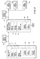
- FIG. 9 is a simplified flow chart showing illustrative methods of making recording media in accordance with this invention.
- FIG. 10 is another view similar to FIG. 2 showing still another illustrative embodiment of a recording medium constructed in accordance with this invention.
- an illustrative two-disc stack 10 has first and second discs 20 and 40 bonded to one another back to back to form the stack.
- Each of discs 20 and 40 has a central aperture.
- these apertures line up with one another to form central stack aperture 12 by which the stack can be placed on a spindle to rotate it about axis 14 for playback of information recorded on the stack.
- disc 20 In stack 10 programming information is recorded on disc 20 in light-readable form in the conventional manner (e.g., generally as shown in Kramer U.S. patent 5,068,846).
- disc 20 typically includes a transparent plastic disc 22, the upper surface of which (as viewed in FIG. 4) is patterned as shown at 24 to record programming information.
- the features of this pattern are sometimes referred to as "pits". These pits are arranged in concentric rings or a continuous spiral substantially concentric with axis 14.
- a layer 26 of highly reflective material such as aluminum is deposited on patterned surface 24. In this way light (typically laser light) directed in through disc 22 toward pattern 24 is reflected back out through disc 22 differently depending on whether the light strikes a high or low spot in pattern 24. The light thereby reads the programming information recorded by pattern 24 in order to play back that programming.
- the recording scheme may be digital.
- a resin layer 28 (e.g., a layer of lacquer) is deposited on the side of layer 26 which faces away from pattern 24.
- disc 40 in stack 10 may have other constructions (described below), in the simplest case (illustrated by FIG. 4) disc 40 is a simple plastic disc 42, preferably of the same material as disc 22 and having substantially the same thickness as the combined thickness of components 22, 26, and 28. Disc 40 is bonded to the exposed surface of layer 28 (e.g., by means of a hot melt glue layer 30).
- disc 40 displays indicia 60 that are visible to the naked eye.
- these indicia include the words “HOME VIDEO”, “THIS SIDE UP”, and "Unauthorized duplication is a violation of law", as well as an annular band 64 of artwork between the two annular bands 62 and 66 of text.
- these indicia are generic, i.e., not specific to the particular programming recorded on the first disc 20 in stack 10.
- Indicia 60 can be applied to disc 40 in any of several ways.
- indicia 60 can be printed on either side of disc 40 before discs 20 and 40 are bonded together.
- indicia 60 can be printed on the exposed surface of disc 40 after discs 20 and 40 have been bonded together (although it is preferred that at least the generic indicia are applied to disc 40 before bonding to disc 20.)
- a printed label e.g., of paper
- Such a label may be applied either before or after discs 20 and 40 are bonded together, although it is again preferred that generic indicia are applied to disc 40 prior to bonding to disc 20.
- FIG. 5 shows an illustrative example 10a in which visible indicia 72 are printed on an annular paper label 70 which is glued to the otherwise exposed surface of disc 40.
- visible indicia 60 may be applied to disc 40 is by locally modifying a surface of disc 40.
- the exposed surface of disc 40 is depressed as at locations 80 to provide visible indicia on the disc.
- These modifications of the surface of disc 40 may be produced in any of several ways such as by thermal branding (i.e., pressing a heated metal pattern against disc 40), by laser scribing, or by selective chemical etching. Again, this modification of the disc surface may be performed before, after, or even during bonding of discs 20 and 40 together, but it is preferred that generic indicia are applied to disc 40 prior to such bonding.
- disc 40 includes a transparent plastic disc 42 with a pattern 44 of surface modifications on one side. Pattern 44 is covered by a layer 46 of highly reflective material such as aluminum. Layer 46 is protected by a layer of lacquer 48. Pattern 44 includes at least two kinds of regions 44a and 44b. In regions 44a pattern 44 includes many small features (like pattern 24). In regions 44b, however, pattern 44 is smooth over relatively large areas. Light passing into disc 42 is reflected back through the disc visibly very differently depending on whether the reflection is from a region 44a or a region 44b.
- Regions 44a tend to scatter the light and therefore appear frosted, while regions 44b have a more mirror-like appearance. These visibly contrasting regions can be used to provide any desired visible indicia.
- line work for lettering or to outline graphics can be provided by lines done like regions 44b against a background like regions 44a. Or lines done like regions 44a can be against a background done like regions 44b. Figures can be done with large areas like regions 44a against a background like regions 44b. Or a figure can be done with large areas like regions 44b against a background like regions 44a.
- Halftone-type shading can be provided by alternating regions like 44a and 44b. Visible indicia produced in this way are sometimes referred to herein as "pit art" because of the use of "pits" like those in pattern 24 to produce some of the features of the indicia.
- pattern 44 can be used to record some generic information that is light-readable for playback in the same way that the programming information can be played back from pattern 24.
- FIG. 8 shows that in addition to visible indicia 80 in text bands 82 and 86 and graphics band 84, pattern 44 may include a small band 88 of generic light-readable information that causes the disc playback apparatus to display a generic message (e.g., "Wrong side -- turn disc over") when band 88 is read in the same way that the playback apparatus would read pattern 24 on disc 20.
- a generic message e.g., "Wrong side -- turn disc over
- FIG. 9 illustrates preferred methods of making discs 10 in accordance with this invention.
- generic discs 40 are made (e.g., using apparatus of the general type that is conventionally used to make CDs or CD-ROMs).
- Step 110 may include one or more of substeps 112, 114, and 116.
- Substep 112 is the printing of generic visible indicia on each disc 40 as has been described above. Any of several printing techniques may be used such as silk screen printing or offset printing.
- Substep 114 is applying a label bearing generic visible indicia to each disc 40 as described above.
- Substep 116 is modifying a surface of each disc 40 to produce visible indicia on the disc.
- Substep 116 may be performed using one or more of further substeps 116a, 116b, and 116c.
- further substep 116a is thermal branding
- further substep 116b is laser scribing
- further substep 116c is the provision of pit art as is described above in connection with FIG. 7.
- step 116c may additionally or alternatively record a generic light-readable message (band 88) on each disc 40.)
- Generic discs 40 leaving step 110 may go directly to step 150 or they may be stockpiled in step 120 for future use in step 150.
- step 130a program discs 20 recorded with programming information "A" are made (e.g., again using apparatus of the general type that is conventionally used to make CDs or CD-ROMs).
- programming information "A” may be a science fiction film.
- step 130b different discs 20 are made with different programming "B” recorded on them.
- programming "B” may be a cartoon film.
- Additional different program discs 20 may be made with still other programming recorded on them in other steps 130 (e.g., in step 130n).
- Program discs from step(s) 130 may go directly to step 150 or they may be stockpiled in step 140 for future use in step 150.
- Step 150 When step 150 is performed, a generic disc 40 from step 110 or stockpile step 120 is bonded back to back with each program disc from a step 130 or from stockpile step 140.
- Step 150 may include one or more of substeps 152, 154, and 156 if it is desired to add specific visible indicia to discs 40.
- additional visible indicia are specific to the programming recorded on the disc 20 to which that disc 40 is bonded.
- the additional specific visible indicia can be the title of the programming on the associated disc 20. An illustration of this is provided in FIG. 10 where the specific visible indicia 90 (i.e., "David Copperfield”) is added to disc 40 in step 150 to identify the programming on the associated disc 20 as a movie entitled "David Copperfield".
- Substep 152 is a printing step similar to above-described step 112.
- Substep 154 is a labelling step similar to above-described labelling step 114.
- Substep 156 is a surface modification step similar to above-described step 116.
- Substep 156 may be performed by way of further substeps 156a and/or 156b, which are respectively similar to further substeps 116a and 116b.
- Substeps 152, 154, and/or 156 may be performed at any convenient time relative to the actual disc bonding portion of step 150.
- substeps 152, 154, and/or 156 may be performed before or after discs 20 and 40 are bonded together in step 150.
- Substep 156a can be performed at either of these times, or it can be performed during the bonding of the discs as part of an operation that presses together the two discs being bonded.
- step 150 The end products of step 150 are finished discs 10 (which is a generic reference to any of the various types of discs 10, 10a, 10b, 10c, and 10d shown in the other FIGS.).
- Producing discs 10 using the methods illustrated by FIG. 9 has a number of advantages.
- generic discs 40 can be made in large quantities in advance of the need for them to be bonded to discs 20. All or substantially all of the work that is needed on these discs 40 can be done on them in advance in step 110. If all the visible indicia that are needed are generic, step 150 can be just the extremely simple and rapid step of bonding two discs 20 and 40 together. Or even if some specific visible indicia are to be added in step 150, that visible indicia can be kept relatively simple and easy to apply because it is only an addition to more sophisticated generic indicia that have already been provided on each disc 40.
- the complicated artwork can be generic artwork done in advance in step 110, with only relatively simple specific artwork added later in step 150.
- step 150 doing as much work as possible on discs 40 in step 110 in advance of the need for those discs helps smooth out the workload of production equipment and personnel.
Landscapes
- Engineering & Computer Science (AREA)
- Manufacturing & Machinery (AREA)
- Optical Recording Or Reproduction (AREA)
- Optical Record Carriers And Manufacture Thereof (AREA)
- Optical Head (AREA)
Claims (25)
- Moyen d'enregistrement d'informations (10), comprenant :caractérisé en ce queun premier disque de matière plastique essentiellement transparent (20) comportant une première surface essentiellement plane (22) et une seconde surface (24) opposée à la première surface (22), la seconde surface (24) comportant des informations enregistrées sur celle-ci au moyen de changements locaux de la distance de cette seconde surface (24) à la première surface (22) ;un premier revêtement réfléchissant la lumière (26) formé sur la seconde surface (24) pour réfléchir la lumière ayant traversé le premier disque (20) de manière à la renvoyer à travers ce premier disque (20), le premier revêtement (26) se conformant aux changements locaux de la seconde surface (24), de façon que la lumière soit réfléchie à travers le premier disque (20) suivant l'information enregistrée au moyen des changements locaux ;un second disque de matière plastique (40) présentant approximativement la même épaisseur que le premier disque (20), ce second disque (40) comportant des troisième (44) et quatrième surfaces, essentiellement planes, le second disque étant empilé et fixé sur le premier disque (20) de façon que la troisième surface (44) soit tournée vers la seconde surface (24) ; etdes repères formés sur le second disque (40) et visibles en regardant la quatrième surface, pour fournir de manière visible à un utilisateur du moyen d'enregistrement (10) une information d'identification concernant le moyen d'enregistrement,
les repères sont formés au moyen de variations d'épaisseur de la matière plastique du second disque (40), ces variations d'épaisseur étant produites par des changements locaux de la distance de la troisième surface (44) à la quatrième surface. - Moyen d'enregistrement (10) selon la revendication 1,
dans lequel
les repères comprennent des modifications locales de la quatrième surface, de façon que la distance de la quatrième surface à la troisième surface (44) soit dans ces modifications locales différente de ce qu'elle est ailleurs. - Moyen d'enregistrement (10) selon la revendication 2,
dans lequel
les modifications locales sont des enfoncements produits thermiquement dans la quatrième surface. - Moyen d'enregistrement (10) selon la revendication 2,
dans lequel
les modifications locales sont des enfoncements produits par un laser dans la quatrième surface. - Moyen d'enregistrement (10) selon la revendication 1,
dans lequel
le second disque (40) est essentiellement transparent, et les repères comprennent des modifications locales de la troisième surface (44), de façon que la distance de cette troisième surface (44) à la quatrième surface, soit dans ces modifications locales différente de ce qu'elle est ailleurs. - Moyen d'enregistrement (10) selon la revendication 5,
comprenant en outre
un second revêtement réfléchissant la lumière visible (46), sur la troisième surface (44), pour réfléchir la lumière visible ayant traversé le second disque (40), de manière à la renvoyer à travers ce second disque (40), le second revêtement (46) se conformant aux modifications locales de la troisième surface, de façon que la lumière visible soit réfléchie à travers le second disque (40) suivant les modifications locales. - Moyen d'enregistrement (10) selon la revendication 6,
dans lequel
les modifications locales comprennent en outre l'enregistrement d'informations supplémentaires lisibles par les mêmes moyens que les informations enregistrées à l'aide des changements locaux. - Moyen d'enregistrement (10) selon la revendication 7,
dans lequel
l'information supplémentaire indique que le second disque (40) n'est pas le disque qui contient l'information enregistrée à l'aide des changements locaux. - Procédé de fabrication de moyens d'enregistrement (10) dont l'un au moins comporte des informations d'un premier programme et d'un second programme enregistrés, respectivement différents, ce procédé comprenant les étapes consistant à :former un certain nombre de premiers disques de matière plastique essentiellement transparents (20) comportant chacun une première surface essentiellement plane (22) et une seconde surface, opposée à la première surface, sur laquelle l'information de premier programme est enregistrée au moyen de changements locaux de la distance de la seconde surface à la première surface (22) ;recouvrir la seconde surface de chacun des premiers disques par un revêtement réflecteur de lumière (24) qui réfléchit la lumière ayant traversé le premier disque (20) pour la renvoyer à travers ce premier disque (20), le revêtement se conformant aux changements locaux de la seconde surface de façon que la lumière soit réfléchie pour repasser à travers le premier disque (20) suivant l'information enregistrée par les changements locaux ;répéter les étapes de formation et de revêtement pour produire un certain nombre de seconds disques essentiellement analogues aux premiers disques (20), sauf qu'une information de second programme est enregistrée sur chacun des seconds disques, au lieu de l'information de premier programme ;former un certain nombre de troisièmes disques de matière plastique essentiellement plans (40) ayant approximativement chacun la même épaisseur que l'un des premiers ou seconds disques (20), et comportant chacun des repères communs à tous les troisièmes disques (40), ces repères étant visibles pour un utilisateur des moyens d'enregistrement de manière à lui fournir une information d'identification visible concernant les moyens d'enregistrement, cette information se caractérisant en ce que les repères sont formés au moyen de variations de l'épaisseur de la matière plastique des troisièmes disques (40) ; etcoller l'un, respectif, des troisièmes disques (40) à chacun des premiers et seconds disques (20) de façon que les disques collés forment une pile de deux disques permanents (10) dans laquelle le troisième disque (40) est adjacent à la seconde surface (24) du premier disque ou du second disque (20) associé, et dans laquelle les repères se trouvant sur le troisième disque (40) sont toujours visibles dans la pile.
- Procédé selon la revendication 9, dans lequel
l'étape de formation d'une pluralité de troisièmes disques (40) comprend l'étape consistant à :
modifier une surface essentiellement plane de chacun des troisièmes disques (40) pour représenter les repères. - Procédé selon la revendication 10,
dans lequel
l'étape de modification comprend l'étape consistant à :
changer l'épaisseur de chacun des troisièmes disques (40) de façon que la surface essentiellement plane de ce disque soit modifiée pour représenter les repères. - Procédé selon la revendication 11,
dans lequel
l'étape de changement comprend l'étape consistant à :
enfoncer thermiquement des parties (116a) de la surface essentiellement plane de chacun des troisièmes disques (40). - Procédé selon la revendication 11,
dans lequel
l'étape de changement comprend l'étape consistant à :
utiliser un laser pour enfoncer des parties (116b) de la surface essentiellement plane de chacun des troisièmes disques (40). - Procédé selon la revendication 10,
dans lequel
chacun des troisièmes disques (40) est essentiellement transparent, et
l'étape de formation d'une pluralité de troisièmes disques (40) comprend en outre l'étape consistant à :
après l'étape de modification, revêtir la surface essentiellement plane de chacun des troisièmes disques (40) par un revêtement réflecteur de lumière visible (46) qui réfléchit la lumière visible ayant traversé le troisième disque pour la faire repasser à travers ce troisième disque, le revêtement (46) se trouvant sur le troisième disque (40) se conformant aux modifications de la surface essentiellement plane, de façon que la lumière visible soit réfléchie pour repasser à travers le troisième disque (40) suivant les repères représentés par ces modifications. - Procédé selon la revendication 14,
dans lequel
l'étape de collage comprend l'étape préliminaire consistant à :
orienter chacun des troisièmes disques (40) de façon que le revêtement (46) se trouvant sur le troisième disque (40) soit adjacent à la seconde surface (24) du premier disque ou du second disque (20) dans la pile comprenant ce troisième disque (40). - Procédé selon la revendication 15,
dans lequel
l'étape de formation de la pluralité de troisièmes disques (40) comprend l'étape consistant à :
modifier en outre la surface essentiellement plane de chacun des troisièmes disques (40) pour enregistrer, sur ce troisième disque, une information supplémentaire (88) lisible par les mêmes moyens que ceux qui lisent les informations de premier programme et de second programme enregistrées sur les premier et second disques (20). - Procédé selon la revendication 16,
dans lequel
l'information supplémentaire (88)indique que le troisième disque (40) n'est pas un disque contenant une information du type des informations des premier ou second programmes. - Procédé selon la revendication 9,
comprenant en outre l'étape consistant à :
après l'étape de collage, appliquer les repères supplémentaires (80, 82, 84, 86) sur le troisième disque (40) de chacune des piles, ces repères supplémentaires (80, 82, 84, 86) étant visibles par l'utilisateur pour lui fournir une information supplémentaire indiquant si la pile comprend l'un des premiers disques (20) contenant l'information de premier programme, ou l'un des seconds disques (20) contenant l'information de second programme. - Procédé selon la revendication 18,
dans lequel
l'étape d'application des repères supplémentaires (80, 82, 84, 86) comprend l'étape consistant à :
imprimer les repères supplémentaires (80, 82, 84, 86) sur une surface essentiellement plane, exposée, du troisième disque (40) dans la pile. - Procédé selon la revendication 18,
dans lequel
l'étape d'application des repères supplémentaires (80, 82, 84, 86) comprend l'étape consistant à :
fixer une étiquette contenant les repères supplémentaires (80, 82, 84, 86) sur une surface essentiellement plane, exposée, du troisième disque (40) dans la pile. - Procédé selon la revendication 18,
dans lequel
l'étape d'application de repères supplémentaires (80, 82, 84, 86) comprend l'étape consistant à :
fixer une étiquette en papier sur laquelle sont imprimés les repères supplémentaires (80, 82, 84, 86), sur une surface essentiellement plane, exposée, du troisième disque (40) dans la pile. - Procédé selon la revendication 18,
dans lequel
l'étape d'application de repères supplémentaires (80, 82, 84, 86) comprend l'étape consistant à :
modifier une surface essentiellement plane, exposée, du troisième disque (40) dans la pile, pour représenter les repères supplémentaires (80, 82, 84, 86). - Procédé selon la revendication 22,
dans lequel
l'étape de modification comprend l'étape consistant à :
changer l'épaisseur du troisième disque (40) dans la pile de façon que la surface essentiellement plane, exposée, du troisième disque, soit modifiée pour représenter les repères supplémentaires (80, 82, 84, 86). - Procédé selon la revendication 23,
dans lequel
l'étape de changement comprend l'étape consistant à :
enfoncer thermiquement des parties (116a) de la surface essentiellement plane, exposée, du troisième disque (40) dans la pile. - Procédé selon la revendication 23,
dans lequel
l'étape de changement comprend l'étape consistant à :
utiliser un laser pour enfoncer des parties (116b) de la surface essentiellement plane, exposée, du troisième disque (40) dans la pile.
Applications Claiming Priority (4)
| Application Number | Priority Date | Filing Date | Title |
|---|---|---|---|
| US361095P | 1995-09-12 | 1995-09-12 | |
| US08/579,302 US5729533A (en) | 1995-09-12 | 1995-12-27 | Two-sided, light-readable information recording disc stacks and methods of making same |
| US579302 | 1995-12-27 | ||
| US3610 | 1998-01-07 |
Publications (3)
| Publication Number | Publication Date |
|---|---|
| EP0762407A2 EP0762407A2 (fr) | 1997-03-12 |
| EP0762407A3 EP0762407A3 (fr) | 1997-11-19 |
| EP0762407B1 true EP0762407B1 (fr) | 2001-05-23 |
Family
ID=26671968
Family Applications (1)
| Application Number | Title | Priority Date | Filing Date |
|---|---|---|---|
| EP96306354A Expired - Lifetime EP0762407B1 (fr) | 1995-09-12 | 1996-09-02 | Piles de disques à double face pour l'enregistrement d'information lisibles optiquement, et méthodes de fabrication |
Country Status (8)
| Country | Link |
|---|---|
| US (1) | US5729533A (fr) |
| EP (1) | EP0762407B1 (fr) |
| JP (1) | JPH09106575A (fr) |
| AT (1) | ATE201525T1 (fr) |
| AU (1) | AU704550B2 (fr) |
| DE (1) | DE69612929T2 (fr) |
| GR (1) | GR3036295T3 (fr) |
| SG (1) | SG42437A1 (fr) |
Cited By (4)
| Publication number | Priority date | Publication date | Assignee | Title |
|---|---|---|---|---|
| US7015939B2 (en) | 2000-10-30 | 2006-03-21 | Yamaha Corporation | Constant angular velocity disk label printing |
| US7129968B2 (en) | 2002-05-31 | 2006-10-31 | Yamaha Corporation | Image forming apparatus capable of forming image on optical disk, and image forming method |
| US7505383B2 (en) | 2002-06-28 | 2009-03-17 | Yamaha Corporation | Optical disc recording apparatus and method of forming an image on an optical disc |
| US7535809B2 (en) | 2001-10-31 | 2009-05-19 | Yamaha Corporation | Optical recording apparatus with drawing capability of visible image on disk face |
Families Citing this family (60)
| Publication number | Priority date | Publication date | Assignee | Title |
|---|---|---|---|---|
| US5726969A (en) * | 1994-12-28 | 1998-03-10 | Matsushita Electric Industrial Co., Ltd. | Optical recording medium having dual information surfaces |
| US5958651A (en) * | 1996-07-11 | 1999-09-28 | Wea Manufacturing Inc. | Methods for providing artwork on plastic information discs |
| WO1998038634A2 (fr) * | 1997-02-28 | 1998-09-03 | Wea Manufacturing, Inc. | Disque compact a etiquette en sandwich, destine a l'enregistrement optique des sons |
| EP0863503A3 (fr) * | 1997-02-28 | 2001-01-31 | Eastman Kodak Company | Disque compact avec des informations perceptibles par l'oeil humain sur une surface intérieure |
| US5766495A (en) * | 1997-03-13 | 1998-06-16 | Wea Manufacturing Inc. | Methods for providing generic and specific artwork on plastic information discs |
| US5946286A (en) * | 1997-03-20 | 1999-08-31 | Imation Corp. | Customized graphics for dual layer optical discs |
| JP2001516491A (ja) * | 1997-03-20 | 2001-09-25 | イメイション・コーポレイション | 光学ディスクのための特別注文グラフィック |
| GB2326014A (en) * | 1997-05-16 | 1998-12-09 | Jan Robert Coyle | A two-sided digital disc |
| US6735166B1 (en) * | 1997-07-09 | 2004-05-11 | Sanyo Electric Co., Ltd. | Optical disk with pattern and fabrication method thereof |
| EP0895242A1 (fr) * | 1997-07-28 | 1999-02-03 | THOMSON multimedia | Méthode de personnalisation d'un support de stockage de données |
| EP0896332B1 (fr) * | 1997-07-28 | 2008-06-04 | THOMSON multimedia | Méthode de personnalisation d'un support de stockage de données |
| TW389900B (en) * | 1997-10-09 | 2000-05-11 | Victor Company Of Japan | Optical disces, producing methods and production apparatus of the optical discs |
| ES2268737T3 (es) * | 1997-11-13 | 2007-03-16 | Sonopress Gmbh | Metodo para producir un soporte optico de datos con informaciones y un holograma. |
| DE29900647U1 (de) | 1998-01-21 | 1999-04-01 | Källn, Marco, Wädenwil | Optisch lesbarer Datenträger |
| US6440248B1 (en) * | 1998-02-02 | 2002-08-27 | Wea Manufacturing Inc. | Two-sided graphical image DVDs and methods for making same |
| US5997976A (en) * | 1998-02-12 | 1999-12-07 | Wea Manufacturing Inc. | Etched mold surface for use in making light-readable discs |
| DE69931704T2 (de) * | 1998-08-10 | 2007-05-10 | Ovd Kinegram Ag | Echtheitsmerkmale für CD's |
| US6507550B1 (en) * | 1998-08-10 | 2003-01-14 | Fuji Photo Film Co., Ltd. | Optical data storage medium |
| US6124011A (en) * | 1998-09-03 | 2000-09-26 | Wea Manufacturing, Inc. | Information-bearing discs and methods of fabrication |
| US6924781B1 (en) * | 1998-09-11 | 2005-08-02 | Visible Tech-Knowledgy, Inc. | Smart electronic label employing electronic ink |
| JP2001283470A (ja) * | 2000-03-31 | 2001-10-12 | Pioneer Electronic Corp | 情報記録システム及び情報記録方法 |
| US6915074B2 (en) * | 2000-03-31 | 2005-07-05 | Eastman Kodak Company | Index prints for photofinishing services |
| JP4278820B2 (ja) * | 2000-03-31 | 2009-06-17 | パイオニア株式会社 | 光ディスク |
| US20020001285A1 (en) | 2000-04-27 | 2002-01-03 | Mitsubishi Chemical Corporation | Optical recording medium |
| US6690642B2 (en) * | 2000-05-17 | 2004-02-10 | Computech International Ventures Limited | Optical disk |
| US20020086319A1 (en) * | 2000-11-13 | 2002-07-04 | Ellson Richard N. | Integrated device with surface-attached molecular moieties and related machine-readable information |
| JP4244551B2 (ja) * | 2001-11-30 | 2009-03-25 | ソニー株式会社 | 記録再生システム |
| JP2003217169A (ja) * | 2001-12-31 | 2003-07-31 | ▲らい▼徳科技股▲ふん▼有限公司 | 複合型光ディスク |
| JP2003217174A (ja) * | 2002-01-21 | 2003-07-31 | Pioneer Electronic Corp | グルーブ間記録方式による光ディスク |
| US7394738B2 (en) * | 2002-03-20 | 2008-07-01 | Hewlett-Packard Development Company, L.P. | Identifying optical disc properties from information read from label side of optical disc |
| US7196715B2 (en) * | 2003-01-17 | 2007-03-27 | Hewlett-Packard Development Company, L.P. | Speed control using drive current profile |
| US7671880B2 (en) * | 2003-01-17 | 2010-03-02 | Hewlett-Packard Development Company, L.P. | Optical disk labeling system and method |
| US7219840B2 (en) | 2003-01-17 | 2007-05-22 | Hewlett-Packard Development Company, L.P. | Calibrating fine actuator using a reference pattern |
| US20040141445A1 (en) * | 2003-01-17 | 2004-07-22 | Hanks Darwin Mitchel | Radial position registration for a trackless optical disc surface |
| WO2004069194A2 (fr) * | 2003-02-03 | 2004-08-19 | The Brigham And Women's Hospital, Inc. | Compositions et procedes pour traiter le diabete |
| US6862033B2 (en) * | 2003-02-14 | 2005-03-01 | Hewlett-Packard Development Company, L.P. | Disc media marking |
| US6866354B2 (en) * | 2003-04-22 | 2005-03-15 | Hewlett-Packard Development Company, L.P. | Disk shape determining and labeling system |
| WO2005022524A2 (fr) * | 2003-08-26 | 2005-03-10 | Communication Synergy Technologies Llc | Conservation de contenu |
| DE20314201U1 (de) | 2003-09-11 | 2003-11-13 | DOCdata Germany Berlin Optical Disc GmbH, 13355 Berlin | Optischer Informationsträger |
| US7177246B2 (en) * | 2003-09-12 | 2007-02-13 | Hewlett-Packard Development Company, L.P. | Optical disk drive focusing apparatus using sum signal |
| US20050058031A1 (en) * | 2003-09-12 | 2005-03-17 | Hanks Darwin Mitchel | Optical disk drive focusing apparatus |
| US7084894B2 (en) * | 2003-09-12 | 2006-08-01 | Hewlett-Packard Development Company, L.P. | Optical disc drive focusing apparatus |
| US20050058043A1 (en) * | 2003-09-12 | 2005-03-17 | Koegler John M. | Optical disk drive modified for speed and orientation tracking |
| US20050058044A1 (en) * | 2003-09-12 | 2005-03-17 | Koegler John M. | Optical disk modified for speed and orientation tracking |
| JP4077781B2 (ja) * | 2003-11-18 | 2008-04-23 | 富士フイルム株式会社 | 光情報記録媒体への可視情報記録方法、及び記録装置 |
| TW200623105A (en) * | 2004-08-30 | 2006-07-01 | Fuji Photo Film Co Ltd | Optical disc |
| SG156686A1 (en) * | 2004-10-28 | 2009-11-26 | Nypro Inc | System, device, and method for producing thin plastic lenses |
| US7496026B2 (en) * | 2004-12-11 | 2009-02-24 | Hewlett-Packard Development Company, L.P. | Optical disc and method of printing optical disc |
| US7324419B2 (en) * | 2004-12-11 | 2008-01-29 | Hewlett-Packard Development Company, L.P. | Focus control via AC input signal |
| US7558183B2 (en) * | 2005-01-07 | 2009-07-07 | Dell Products L.P. | System and method for optical media marking |
| EP1894189A2 (fr) * | 2005-06-15 | 2008-03-05 | Koninklijke Philips Electronics N.V. | Procede permettant d'ecrire sur un support d'enregistrement optique, support d'enregistrement optique et procede de fabrication du support d'enregistrement optique |
| WO2007038081A2 (fr) * | 2005-09-21 | 2007-04-05 | Doug Carson Associates | Support de stockage presentant des pistes separees pour les images et les donnees |
| ATE472798T1 (de) * | 2006-05-05 | 2010-07-15 | Moser Baer India Ltd | Verfahren zum drucken auf eine platte |
| DE102006052347A1 (de) * | 2006-11-07 | 2008-05-08 | Bönigk, Peter | Bedrucken von scheibenförmiger Datenträger |
| JP4020166B2 (ja) * | 2007-05-11 | 2007-12-12 | ヤマハ株式会社 | プログラム |
| US20100177080A1 (en) * | 2009-01-13 | 2010-07-15 | Metrologic Instruments, Inc. | Electronic-ink signage device employing thermal packaging for outdoor weather applications |
| US8234507B2 (en) | 2009-01-13 | 2012-07-31 | Metrologic Instruments, Inc. | Electronic-ink display device employing a power switching mechanism automatically responsive to predefined states of device configuration |
| US20100177750A1 (en) * | 2009-01-13 | 2010-07-15 | Metrologic Instruments, Inc. | Wireless Diplay sensor communication network |
| US20100177076A1 (en) * | 2009-01-13 | 2010-07-15 | Metrologic Instruments, Inc. | Edge-lit electronic-ink display device for use in indoor and outdoor environments |
| US8457013B2 (en) | 2009-01-13 | 2013-06-04 | Metrologic Instruments, Inc. | Wireless dual-function network device dynamically switching and reconfiguring from a wireless network router state of operation into a wireless network coordinator state of operation in a wireless communication network |
Citations (1)
| Publication number | Priority date | Publication date | Assignee | Title |
|---|---|---|---|---|
| US5068846A (en) * | 1972-09-02 | 1991-11-26 | U.S. Philips Corporation | Reflective optical record carrier |
Family Cites Families (19)
| Publication number | Priority date | Publication date | Assignee | Title |
|---|---|---|---|---|
| US3689078A (en) * | 1969-06-30 | 1972-09-05 | Yasujiro Ban | Colored recording discs |
| JPS57169938A (en) * | 1981-04-10 | 1982-10-19 | Sony Corp | Optical type recording medium |
| US4629668A (en) * | 1985-03-12 | 1986-12-16 | Quixote Corporation | Optically read recording medium and method for making same |
| JPH0650876Y2 (ja) * | 1987-03-31 | 1994-12-21 | 三洋電機株式会社 | 光学式オーディオディスク |
| WO1989009989A1 (fr) * | 1988-04-12 | 1989-10-19 | Dia Nippon Insatsu Kabushiki Kaisha | Support d'enregistrement optique et procede de fabrication |
| JPH0728590Y2 (ja) * | 1988-09-29 | 1995-06-28 | パイオニア株式会社 | 光学式情報記録担体 |
| US4967286A (en) * | 1988-12-12 | 1990-10-30 | Disctronics Manufacturing, Inc. | Method and apparatus for forming a digital image on an optical recording disc |
| JP2514261B2 (ja) * | 1990-01-11 | 1996-07-10 | 松下電器産業株式会社 | 光情報媒体、その製造方法、及びそのカセットケ―ス |
| JP3109866B2 (ja) * | 1990-11-17 | 2000-11-20 | 太陽誘電株式会社 | 光学式情報記録担体用基板及びその製造方法 |
| CA2066936A1 (fr) * | 1991-05-16 | 1992-11-17 | Donald Spector | Boitier de disque compact |
| US5255262A (en) * | 1991-06-04 | 1993-10-19 | International Business Machines Corporation | Multiple data surface optical data storage system with transmissive data surfaces |
| JPH0554599A (ja) * | 1991-08-26 | 1993-03-05 | Nec Corp | 光デイスク |
| US5470627A (en) * | 1992-03-06 | 1995-11-28 | Quantum Corporation | Double-sided optical media for a disk storage device |
| TW247960B (fr) * | 1992-11-16 | 1995-05-21 | Canon Kk | |
| KR0180795B1 (ko) * | 1993-07-28 | 1999-04-15 | 이리마지리 쇼우이찌로 | 정보 기억 매체 및 그것을 이용하는 전자 장치 |
| FR2710443B1 (fr) * | 1993-09-22 | 1995-11-10 | Digipress Sa | Procédé d'enregistrement d'informations sur un disque optique et de lecture de celles-ci, support d'enregistrement et agencement de lecture pour la mise en Óoeuvre du procédé. |
| FR2725069B1 (fr) * | 1994-09-28 | 1997-01-03 | Digipress Sa | Disque compact comportant un marquage anti-piratage, moule de pressage et procede de marquage anti-piratage de disques compacts |
| DE69520920T2 (de) * | 1994-10-03 | 2001-09-27 | Matsushita Electric Industrial Co., Ltd. | Optisches Informationsmedium, sowie Einheit und Verfahren zu dessen Herstellung |
| JPH08194972A (ja) * | 1995-01-12 | 1996-07-30 | Pioneer Video Corp | 光ディスク及びその製造装置 |
-
1995
- 1995-12-27 US US08/579,302 patent/US5729533A/en not_active Expired - Lifetime
-
1996
- 1996-09-02 DE DE69612929T patent/DE69612929T2/de not_active Expired - Lifetime
- 1996-09-02 AT AT96306354T patent/ATE201525T1/de not_active IP Right Cessation
- 1996-09-02 EP EP96306354A patent/EP0762407B1/fr not_active Expired - Lifetime
- 1996-09-04 SG SG1996010571A patent/SG42437A1/en unknown
- 1996-09-11 AU AU65586/96A patent/AU704550B2/en not_active Ceased
- 1996-09-12 JP JP8242392A patent/JPH09106575A/ja active Pending
-
2001
- 2001-07-30 GR GR20010401145T patent/GR3036295T3/el not_active IP Right Cessation
Patent Citations (1)
| Publication number | Priority date | Publication date | Assignee | Title |
|---|---|---|---|---|
| US5068846A (en) * | 1972-09-02 | 1991-11-26 | U.S. Philips Corporation | Reflective optical record carrier |
Cited By (13)
| Publication number | Priority date | Publication date | Assignee | Title |
|---|---|---|---|---|
| US7436420B2 (en) | 2000-10-30 | 2008-10-14 | Yamaha Corporation | System and method for controlling a tracking servo during label printing |
| US7268794B2 (en) | 2000-10-30 | 2007-09-11 | Yamaha Corporation | Method of printing label on optical disk, optical disk unit, and optical disk |
| US7336293B2 (en) | 2000-10-30 | 2008-02-26 | Yamaha Corporation | Scanning optical media during label printing |
| US7336292B2 (en) | 2000-10-30 | 2008-02-26 | Yamaha Corporation | Optical media label printing using different power levels |
| US7015939B2 (en) | 2000-10-30 | 2006-03-21 | Yamaha Corporation | Constant angular velocity disk label printing |
| US7471305B2 (en) | 2000-10-30 | 2008-12-30 | Yamaha Corporation | Constant angular velocity disk label printing |
| US7561174B2 (en) | 2000-10-30 | 2009-07-14 | Yamaha Corporation | Optical media printing using a vibration signal |
| US7675535B2 (en) | 2000-10-30 | 2010-03-09 | Yamaha Corporation | System and method for controlling a tracking servo during label printing |
| US7869340B2 (en) | 2000-10-30 | 2011-01-11 | Yamaha Corporation | Method of printing label on optical disk, optical disk unit, and optical disk |
| US7535809B2 (en) | 2001-10-31 | 2009-05-19 | Yamaha Corporation | Optical recording apparatus with drawing capability of visible image on disk face |
| US7129968B2 (en) | 2002-05-31 | 2006-10-31 | Yamaha Corporation | Image forming apparatus capable of forming image on optical disk, and image forming method |
| US7362348B2 (en) | 2002-05-31 | 2008-04-22 | Yamaha Corporation | Image forming apparatus capable of forming image on optical disk, and image forming method |
| US7505383B2 (en) | 2002-06-28 | 2009-03-17 | Yamaha Corporation | Optical disc recording apparatus and method of forming an image on an optical disc |
Also Published As
| Publication number | Publication date |
|---|---|
| EP0762407A3 (fr) | 1997-11-19 |
| US5729533A (en) | 1998-03-17 |
| GR3036295T3 (en) | 2001-10-31 |
| SG42437A1 (en) | 1997-08-15 |
| DE69612929D1 (de) | 2001-06-28 |
| JPH09106575A (ja) | 1997-04-22 |
| AU6558696A (en) | 1997-03-20 |
| EP0762407A2 (fr) | 1997-03-12 |
| AU704550B2 (en) | 1999-04-29 |
| DE69612929T2 (de) | 2002-03-28 |
| ATE201525T1 (de) | 2001-06-15 |
Similar Documents
| Publication | Publication Date | Title |
|---|---|---|
| EP0762407B1 (fr) | Piles de disques à double face pour l'enregistrement d'information lisibles optiquement, et méthodes de fabrication | |
| AU752595B2 (en) | Two-sided graphical image DVDs and methods for making same | |
| US5809003A (en) | Optical disk and optical information reproducing apparatus | |
| EP0984442B1 (fr) | Supports d'informations et procédés de fabrication | |
| US8264943B2 (en) | Information recording medium and reproducing apparatus therefor | |
| US5805563A (en) | Optical information recording medium on which a visible display having a stereoscopically view effect and a depth viewing effect can be made | |
| US20040152501A1 (en) | Gaming machine and display device therefor | |
| US5982737A (en) | Optical disk having first design visible from one side of the disk and a second design visible from the other side of the disk | |
| WO2005104112A2 (fr) | Disque optique presentant une surface lenticulaire et son procede de fabrication | |
| JPH08273331A (ja) | 光ディスクおよびその製造方法 | |
| JPH0991762A (ja) | 光学式記録媒体 | |
| JP3681281B2 (ja) | 光情報記録媒体 | |
| JP3585982B2 (ja) | 光学ディスク構体 | |
| JP3228148B2 (ja) | 光ディスク及び光ディスクの製造方法 | |
| JPH08287522A (ja) | 光ディスクおよびその製造方法 | |
| JP3607345B2 (ja) | 光学ディスク構体 | |
| KR20030089940A (ko) | 라벨이 기록된 광 기록매체, 광 기록 매체에 라벨을기록하는 장치 및 방법 | |
| KR20030079174A (ko) | 라벨이 기록된 광 기록매체, 광 기록 매체에 라벨을기록하는 장치 및 방법 | |
| JPH08255381A (ja) | 光学式ディスク | |
| WO1998038634A2 (fr) | Disque compact a etiquette en sandwich, destine a l'enregistrement optique des sons | |
| JP2001195783A (ja) | 光記録媒体およびその製造方法 | |
| JPH103698A (ja) | 光ディスク | |
| JPH08297864A (ja) | 光ディスク媒体 |
Legal Events
| Date | Code | Title | Description |
|---|---|---|---|
| PUAI | Public reference made under article 153(3) epc to a published international application that has entered the european phase |
Free format text: ORIGINAL CODE: 0009012 |
|
| AK | Designated contracting states |
Kind code of ref document: A2 Designated state(s): AT BE DE FR GB GR IT NL |
|
| PUAL | Search report despatched |
Free format text: ORIGINAL CODE: 0009013 |
|
| AK | Designated contracting states |
Kind code of ref document: A3 Designated state(s): AT BE DE FR GB GR IT NL |
|
| 17P | Request for examination filed |
Effective date: 19971212 |
|
| 17Q | First examination report despatched |
Effective date: 19990630 |
|
| GRAG | Despatch of communication of intention to grant |
Free format text: ORIGINAL CODE: EPIDOS AGRA |
|
| GRAG | Despatch of communication of intention to grant |
Free format text: ORIGINAL CODE: EPIDOS AGRA |
|
| GRAH | Despatch of communication of intention to grant a patent |
Free format text: ORIGINAL CODE: EPIDOS IGRA |
|
| GRAH | Despatch of communication of intention to grant a patent |
Free format text: ORIGINAL CODE: EPIDOS IGRA |
|
| GRAA | (expected) grant |
Free format text: ORIGINAL CODE: 0009210 |
|
| AK | Designated contracting states |
Kind code of ref document: B1 Designated state(s): AT BE DE FR GB GR IT NL |
|
| REF | Corresponds to: |
Ref document number: 201525 Country of ref document: AT Date of ref document: 20010615 Kind code of ref document: T |
|
| REF | Corresponds to: |
Ref document number: 69612929 Country of ref document: DE Date of ref document: 20010628 |
|
| ITF | It: translation for a ep patent filed | ||
| ET | Fr: translation filed | ||
| REG | Reference to a national code |
Ref country code: GB Ref legal event code: IF02 |
|
| PLBE | No opposition filed within time limit |
Free format text: ORIGINAL CODE: 0009261 |
|
| STAA | Information on the status of an ep patent application or granted ep patent |
Free format text: STATUS: NO OPPOSITION FILED WITHIN TIME LIMIT |
|
| 26N | No opposition filed | ||
| PGFP | Annual fee paid to national office [announced via postgrant information from national office to epo] |
Ref country code: FR Payment date: 20020731 Year of fee payment: 7 |
|
| PGFP | Annual fee paid to national office [announced via postgrant information from national office to epo] |
Ref country code: AT Payment date: 20020913 Year of fee payment: 7 |
|
| PGFP | Annual fee paid to national office [announced via postgrant information from national office to epo] |
Ref country code: GR Payment date: 20020924 Year of fee payment: 7 |
|
| PG25 | Lapsed in a contracting state [announced via postgrant information from national office to epo] |
Ref country code: AT Free format text: LAPSE BECAUSE OF NON-PAYMENT OF DUE FEES Effective date: 20030902 |
|
| PG25 | Lapsed in a contracting state [announced via postgrant information from national office to epo] |
Ref country code: GR Free format text: LAPSE BECAUSE OF NON-PAYMENT OF DUE FEES Effective date: 20040402 |
|
| PG25 | Lapsed in a contracting state [announced via postgrant information from national office to epo] |
Ref country code: FR Free format text: LAPSE BECAUSE OF NON-PAYMENT OF DUE FEES Effective date: 20040528 |
|
| REG | Reference to a national code |
Ref country code: FR Ref legal event code: ST |
|
| PGFP | Annual fee paid to national office [announced via postgrant information from national office to epo] |
Ref country code: IT Payment date: 20080130 Year of fee payment: 12 Ref country code: GB Payment date: 20080129 Year of fee payment: 12 |
|
| PGFP | Annual fee paid to national office [announced via postgrant information from national office to epo] |
Ref country code: BE Payment date: 20080206 Year of fee payment: 12 |
|
| BERE | Be: lapsed |
Owner name: *WEA MFG INC. Effective date: 20080930 |
|
| GBPC | Gb: european patent ceased through non-payment of renewal fee |
Effective date: 20080902 |
|
| PG25 | Lapsed in a contracting state [announced via postgrant information from national office to epo] |
Ref country code: BE Free format text: LAPSE BECAUSE OF NON-PAYMENT OF DUE FEES Effective date: 20080930 |
|
| PG25 | Lapsed in a contracting state [announced via postgrant information from national office to epo] |
Ref country code: IT Free format text: LAPSE BECAUSE OF NON-PAYMENT OF DUE FEES Effective date: 20080902 |
|
| PG25 | Lapsed in a contracting state [announced via postgrant information from national office to epo] |
Ref country code: GB Free format text: LAPSE BECAUSE OF NON-PAYMENT OF DUE FEES Effective date: 20080902 |
|
| PGFP | Annual fee paid to national office [announced via postgrant information from national office to epo] |
Ref country code: DE Payment date: 20150825 Year of fee payment: 20 |
|
| PGFP | Annual fee paid to national office [announced via postgrant information from national office to epo] |
Ref country code: NL Payment date: 20150909 Year of fee payment: 20 |
|
| REG | Reference to a national code |
Ref country code: DE Ref legal event code: R071 Ref document number: 69612929 Country of ref document: DE |
|
| REG | Reference to a national code |
Ref country code: NL Ref legal event code: MK Effective date: 20160901 |