EP0744651A2 - Multiformat-Kamera, die Bildgrösse-Information auf den Film aufzeichnet, sowie photographischer Printer und Vorrichtung zur Videokonversion photographischer Bilder - Google Patents
Multiformat-Kamera, die Bildgrösse-Information auf den Film aufzeichnet, sowie photographischer Printer und Vorrichtung zur Videokonversion photographischer Bilder Download PDFInfo
- Publication number
- EP0744651A2 EP0744651A2 EP96303473A EP96303473A EP0744651A2 EP 0744651 A2 EP0744651 A2 EP 0744651A2 EP 96303473 A EP96303473 A EP 96303473A EP 96303473 A EP96303473 A EP 96303473A EP 0744651 A2 EP0744651 A2 EP 0744651A2
- Authority
- EP
- European Patent Office
- Prior art keywords
- film
- photographic
- image
- photographic film
- signal
- Prior art date
- Legal status (The legal status is an assumption and is not a legal conclusion. Google has not performed a legal analysis and makes no representation as to the accuracy of the status listed.)
- Granted
Links
- 230000003287 optical effect Effects 0.000 claims abstract description 12
- 238000000034 method Methods 0.000 claims description 30
- 230000001131 transforming effect Effects 0.000 claims description 26
- 230000004044 response Effects 0.000 claims description 22
- 239000011295 pitch Substances 0.000 description 39
- 230000008569 process Effects 0.000 description 26
- 238000012545 processing Methods 0.000 description 13
- 238000012546 transfer Methods 0.000 description 9
- 238000012937 correction Methods 0.000 description 8
- 238000010586 diagram Methods 0.000 description 7
- 230000007246 mechanism Effects 0.000 description 7
- 239000002131 composite material Substances 0.000 description 4
- 238000012790 confirmation Methods 0.000 description 4
- 230000035945 sensitivity Effects 0.000 description 4
- 238000004804 winding Methods 0.000 description 3
- UQSXHKLRYXJYBZ-UHFFFAOYSA-N Iron oxide Chemical compound [Fe]=O UQSXHKLRYXJYBZ-UHFFFAOYSA-N 0.000 description 2
- 230000008859 change Effects 0.000 description 2
- 239000000696 magnetic material Substances 0.000 description 2
- 230000005855 radiation Effects 0.000 description 2
- 230000009466 transformation Effects 0.000 description 2
- 238000010923 batch production Methods 0.000 description 1
- 238000006243 chemical reaction Methods 0.000 description 1
- 238000004891 communication Methods 0.000 description 1
- 230000001419 dependent effect Effects 0.000 description 1
- 230000000994 depressogenic effect Effects 0.000 description 1
- 238000001514 detection method Methods 0.000 description 1
- 238000009792 diffusion process Methods 0.000 description 1
- 239000011521 glass Substances 0.000 description 1
- 238000003384 imaging method Methods 0.000 description 1
- 238000011017 operating method Methods 0.000 description 1
- 230000008520 organization Effects 0.000 description 1
- 230000004800 psychological effect Effects 0.000 description 1
- 230000007723 transport mechanism Effects 0.000 description 1
- 238000003079 width control Methods 0.000 description 1
Images


Classifications
-
- G—PHYSICS
- G03—PHOTOGRAPHY; CINEMATOGRAPHY; ANALOGOUS TECHNIQUES USING WAVES OTHER THAN OPTICAL WAVES; ELECTROGRAPHY; HOLOGRAPHY
- G03B—APPARATUS OR ARRANGEMENTS FOR TAKING PHOTOGRAPHS OR FOR PROJECTING OR VIEWING THEM; APPARATUS OR ARRANGEMENTS EMPLOYING ANALOGOUS TECHNIQUES USING WAVES OTHER THAN OPTICAL WAVES; ACCESSORIES THEREFOR
- G03B1/00—Film strip handling
-
- H—ELECTRICITY
- H04—ELECTRIC COMMUNICATION TECHNIQUE
- H04N—PICTORIAL COMMUNICATION, e.g. TELEVISION
- H04N1/00—Scanning, transmission or reproduction of documents or the like, e.g. facsimile transmission; Details thereof
- H04N1/32—Circuits or arrangements for control or supervision between transmitter and receiver or between image input and image output device, e.g. between a still-image camera and its memory or between a still-image camera and a printer device
- H04N1/32101—Display, printing, storage or transmission of additional information, e.g. ID code, date and time or title
- H04N1/32128—Display, printing, storage or transmission of additional information, e.g. ID code, date and time or title attached to the image data, e.g. file header, transmitted message header, information on the same page or in the same computer file as the image
-
- G—PHYSICS
- G03—PHOTOGRAPHY; CINEMATOGRAPHY; ANALOGOUS TECHNIQUES USING WAVES OTHER THAN OPTICAL WAVES; ELECTROGRAPHY; HOLOGRAPHY
- G03B—APPARATUS OR ARRANGEMENTS FOR TAKING PHOTOGRAPHS OR FOR PROJECTING OR VIEWING THEM; APPARATUS OR ARRANGEMENTS EMPLOYING ANALOGOUS TECHNIQUES USING WAVES OTHER THAN OPTICAL WAVES; ACCESSORIES THEREFOR
- G03B1/00—Film strip handling
- G03B1/42—Guiding, framing, or constraining film in desired position relative to lens system
- G03B1/48—Gates or pressure devices, e.g. plate
- G03B1/50—Gates or pressure devices, e.g. plate adjustable or interchangeable, e.g. for different film widths
-
- G—PHYSICS
- G03—PHOTOGRAPHY; CINEMATOGRAPHY; ANALOGOUS TECHNIQUES USING WAVES OTHER THAN OPTICAL WAVES; ELECTROGRAPHY; HOLOGRAPHY
- G03B—APPARATUS OR ARRANGEMENTS FOR TAKING PHOTOGRAPHS OR FOR PROJECTING OR VIEWING THEM; APPARATUS OR ARRANGEMENTS EMPLOYING ANALOGOUS TECHNIQUES USING WAVES OTHER THAN OPTICAL WAVES; ACCESSORIES THEREFOR
- G03B17/00—Details of cameras or camera bodies; Accessories therefor
- G03B17/24—Details of cameras or camera bodies; Accessories therefor with means for separately producing marks on the film, e.g. title, time of exposure
- G03B17/245—Optical means
-
- G—PHYSICS
- G03—PHOTOGRAPHY; CINEMATOGRAPHY; ANALOGOUS TECHNIQUES USING WAVES OTHER THAN OPTICAL WAVES; ELECTROGRAPHY; HOLOGRAPHY
- G03B—APPARATUS OR ARRANGEMENTS FOR TAKING PHOTOGRAPHS OR FOR PROJECTING OR VIEWING THEM; APPARATUS OR ARRANGEMENTS EMPLOYING ANALOGOUS TECHNIQUES USING WAVES OTHER THAN OPTICAL WAVES; ACCESSORIES THEREFOR
- G03B17/00—Details of cameras or camera bodies; Accessories therefor
- G03B17/48—Details of cameras or camera bodies; Accessories therefor adapted for combination with other photographic or optical apparatus
-
- G—PHYSICS
- G03—PHOTOGRAPHY; CINEMATOGRAPHY; ANALOGOUS TECHNIQUES USING WAVES OTHER THAN OPTICAL WAVES; ELECTROGRAPHY; HOLOGRAPHY
- G03B—APPARATUS OR ARRANGEMENTS FOR TAKING PHOTOGRAPHS OR FOR PROJECTING OR VIEWING THEM; APPARATUS OR ARRANGEMENTS EMPLOYING ANALOGOUS TECHNIQUES USING WAVES OTHER THAN OPTICAL WAVES; ACCESSORIES THEREFOR
- G03B27/00—Photographic printing apparatus
- G03B27/32—Projection printing apparatus, e.g. enlarger, copying camera
- G03B27/46—Projection printing apparatus, e.g. enlarger, copying camera for automatic sequential copying of different originals, e.g. enlargers, roll film printers
- G03B27/462—Projection printing apparatus, e.g. enlarger, copying camera for automatic sequential copying of different originals, e.g. enlargers, roll film printers in enlargers, e.g. roll film printers
-
- G—PHYSICS
- G03—PHOTOGRAPHY; CINEMATOGRAPHY; ANALOGOUS TECHNIQUES USING WAVES OTHER THAN OPTICAL WAVES; ELECTROGRAPHY; HOLOGRAPHY
- G03B—APPARATUS OR ARRANGEMENTS FOR TAKING PHOTOGRAPHS OR FOR PROJECTING OR VIEWING THEM; APPARATUS OR ARRANGEMENTS EMPLOYING ANALOGOUS TECHNIQUES USING WAVES OTHER THAN OPTICAL WAVES; ACCESSORIES THEREFOR
- G03B27/00—Photographic printing apparatus
- G03B27/32—Projection printing apparatus, e.g. enlarger, copying camera
- G03B27/52—Details
- G03B27/62—Holders for the original
- G03B27/6271—Holders for the original in enlargers
- G03B27/6285—Handling strips
-
- H—ELECTRICITY
- H04—ELECTRIC COMMUNICATION TECHNIQUE
- H04N—PICTORIAL COMMUNICATION, e.g. TELEVISION
- H04N1/00—Scanning, transmission or reproduction of documents or the like, e.g. facsimile transmission; Details thereof
- H04N1/00127—Connection or combination of a still picture apparatus with another apparatus, e.g. for storage, processing or transmission of still picture signals or of information associated with a still picture
- H04N1/00129—Connection or combination of a still picture apparatus with another apparatus, e.g. for storage, processing or transmission of still picture signals or of information associated with a still picture with a display device, e.g. CRT or LCD monitor
-
- H—ELECTRICITY
- H04—ELECTRIC COMMUNICATION TECHNIQUE
- H04N—PICTORIAL COMMUNICATION, e.g. TELEVISION
- H04N1/00—Scanning, transmission or reproduction of documents or the like, e.g. facsimile transmission; Details thereof
- H04N1/00127—Connection or combination of a still picture apparatus with another apparatus, e.g. for storage, processing or transmission of still picture signals or of information associated with a still picture
- H04N1/00132—Connection or combination of a still picture apparatus with another apparatus, e.g. for storage, processing or transmission of still picture signals or of information associated with a still picture in a digital photofinishing system, i.e. a system where digital photographic images undergo typical photofinishing processing, e.g. printing ordering
- H04N1/00143—Ordering
-
- H—ELECTRICITY
- H04—ELECTRIC COMMUNICATION TECHNIQUE
- H04N—PICTORIAL COMMUNICATION, e.g. TELEVISION
- H04N1/00—Scanning, transmission or reproduction of documents or the like, e.g. facsimile transmission; Details thereof
- H04N1/00127—Connection or combination of a still picture apparatus with another apparatus, e.g. for storage, processing or transmission of still picture signals or of information associated with a still picture
- H04N1/00249—Connection or combination of a still picture apparatus with another apparatus, e.g. for storage, processing or transmission of still picture signals or of information associated with a still picture with a photographic apparatus, e.g. a photographic printer or a projector
- H04N1/00265—Connection or combination of a still picture apparatus with another apparatus, e.g. for storage, processing or transmission of still picture signals or of information associated with a still picture with a photographic apparatus, e.g. a photographic printer or a projector with a photographic printing apparatus
-
- H—ELECTRICITY
- H04—ELECTRIC COMMUNICATION TECHNIQUE
- H04N—PICTORIAL COMMUNICATION, e.g. TELEVISION
- H04N1/00—Scanning, transmission or reproduction of documents or the like, e.g. facsimile transmission; Details thereof
- H04N1/00127—Connection or combination of a still picture apparatus with another apparatus, e.g. for storage, processing or transmission of still picture signals or of information associated with a still picture
- H04N1/00249—Connection or combination of a still picture apparatus with another apparatus, e.g. for storage, processing or transmission of still picture signals or of information associated with a still picture with a photographic apparatus, e.g. a photographic printer or a projector
- H04N1/00267—Connection or combination of a still picture apparatus with another apparatus, e.g. for storage, processing or transmission of still picture signals or of information associated with a still picture with a photographic apparatus, e.g. a photographic printer or a projector with a viewing or projecting apparatus, e.g. for reading image information from a film
-
- H—ELECTRICITY
- H04—ELECTRIC COMMUNICATION TECHNIQUE
- H04N—PICTORIAL COMMUNICATION, e.g. TELEVISION
- H04N1/00—Scanning, transmission or reproduction of documents or the like, e.g. facsimile transmission; Details thereof
- H04N1/00127—Connection or combination of a still picture apparatus with another apparatus, e.g. for storage, processing or transmission of still picture signals or of information associated with a still picture
- H04N1/00249—Connection or combination of a still picture apparatus with another apparatus, e.g. for storage, processing or transmission of still picture signals or of information associated with a still picture with a photographic apparatus, e.g. a photographic printer or a projector
- H04N1/0027—Reading or writing of non-image information from or to a photographic material, e.g. processing data stored in a magnetic track
-
- H—ELECTRICITY
- H04—ELECTRIC COMMUNICATION TECHNIQUE
- H04N—PICTORIAL COMMUNICATION, e.g. TELEVISION
- H04N1/00—Scanning, transmission or reproduction of documents or the like, e.g. facsimile transmission; Details thereof
- H04N1/00127—Connection or combination of a still picture apparatus with another apparatus, e.g. for storage, processing or transmission of still picture signals or of information associated with a still picture
- H04N1/00326—Connection or combination of a still picture apparatus with another apparatus, e.g. for storage, processing or transmission of still picture signals or of information associated with a still picture with a data reading, recognizing or recording apparatus, e.g. with a bar-code apparatus
-
- H—ELECTRICITY
- H04—ELECTRIC COMMUNICATION TECHNIQUE
- H04N—PICTORIAL COMMUNICATION, e.g. TELEVISION
- H04N1/00—Scanning, transmission or reproduction of documents or the like, e.g. facsimile transmission; Details thereof
- H04N1/00962—Input arrangements for operating instructions or parameters, e.g. updating internal software
-
- H—ELECTRICITY
- H04—ELECTRIC COMMUNICATION TECHNIQUE
- H04N—PICTORIAL COMMUNICATION, e.g. TELEVISION
- H04N1/00—Scanning, transmission or reproduction of documents or the like, e.g. facsimile transmission; Details thereof
- H04N1/04—Scanning arrangements, i.e. arrangements for the displacement of active reading or reproducing elements relative to the original or reproducing medium, or vice versa
- H04N1/0402—Scanning different formats; Scanning with different densities of dots per unit length, e.g. different numbers of dots per inch (dpi); Conversion of scanning standards
- H04N1/0405—Different formats, e.g. A3 and A4
-
- H—ELECTRICITY
- H04—ELECTRIC COMMUNICATION TECHNIQUE
- H04N—PICTORIAL COMMUNICATION, e.g. TELEVISION
- H04N1/00—Scanning, transmission or reproduction of documents or the like, e.g. facsimile transmission; Details thereof
- H04N1/04—Scanning arrangements, i.e. arrangements for the displacement of active reading or reproducing elements relative to the original or reproducing medium, or vice versa
- H04N1/0402—Scanning different formats; Scanning with different densities of dots per unit length, e.g. different numbers of dots per inch (dpi); Conversion of scanning standards
- H04N1/042—Details of the method used
- H04N1/0432—Varying the magnification of a single lens group
-
- H—ELECTRICITY
- H04—ELECTRIC COMMUNICATION TECHNIQUE
- H04N—PICTORIAL COMMUNICATION, e.g. TELEVISION
- H04N1/00—Scanning, transmission or reproduction of documents or the like, e.g. facsimile transmission; Details thereof
- H04N1/04—Scanning arrangements, i.e. arrangements for the displacement of active reading or reproducing elements relative to the original or reproducing medium, or vice versa
- H04N1/0402—Scanning different formats; Scanning with different densities of dots per unit length, e.g. different numbers of dots per inch (dpi); Conversion of scanning standards
- H04N1/042—Details of the method used
- H04N1/0455—Details of the method used using a single set of scanning elements, e.g. the whole of and a part of an array respectively for different formats
- H04N1/0458—Details of the method used using a single set of scanning elements, e.g. the whole of and a part of an array respectively for different formats using different portions of the scanning elements for different formats or densities of dots
-
- H—ELECTRICITY
- H04—ELECTRIC COMMUNICATION TECHNIQUE
- H04N—PICTORIAL COMMUNICATION, e.g. TELEVISION
- H04N1/00—Scanning, transmission or reproduction of documents or the like, e.g. facsimile transmission; Details thereof
- H04N1/04—Scanning arrangements, i.e. arrangements for the displacement of active reading or reproducing elements relative to the original or reproducing medium, or vice versa
- H04N1/19—Scanning arrangements, i.e. arrangements for the displacement of active reading or reproducing elements relative to the original or reproducing medium, or vice versa using multi-element arrays
- H04N1/195—Scanning arrangements, i.e. arrangements for the displacement of active reading or reproducing elements relative to the original or reproducing medium, or vice versa using multi-element arrays the array comprising a two-dimensional array or a combination of two-dimensional arrays
-
- H—ELECTRICITY
- H04—ELECTRIC COMMUNICATION TECHNIQUE
- H04N—PICTORIAL COMMUNICATION, e.g. TELEVISION
- H04N1/00—Scanning, transmission or reproduction of documents or the like, e.g. facsimile transmission; Details thereof
- H04N1/32—Circuits or arrangements for control or supervision between transmitter and receiver or between image input and image output device, e.g. between a still-image camera and its memory or between a still-image camera and a printer device
- H04N1/32101—Display, printing, storage or transmission of additional information, e.g. ID code, date and time or title
- H04N1/32128—Display, printing, storage or transmission of additional information, e.g. ID code, date and time or title attached to the image data, e.g. file header, transmitted message header, information on the same page or in the same computer file as the image
- H04N1/32133—Display, printing, storage or transmission of additional information, e.g. ID code, date and time or title attached to the image data, e.g. file header, transmitted message header, information on the same page or in the same computer file as the image on the same paper sheet, e.g. a facsimile page header
-
- G—PHYSICS
- G03—PHOTOGRAPHY; CINEMATOGRAPHY; ANALOGOUS TECHNIQUES USING WAVES OTHER THAN OPTICAL WAVES; ELECTROGRAPHY; HOLOGRAPHY
- G03B—APPARATUS OR ARRANGEMENTS FOR TAKING PHOTOGRAPHS OR FOR PROJECTING OR VIEWING THEM; APPARATUS OR ARRANGEMENTS EMPLOYING ANALOGOUS TECHNIQUES USING WAVES OTHER THAN OPTICAL WAVES; ACCESSORIES THEREFOR
- G03B2206/00—Systems for exchange of information between different pieces of apparatus, e.g. for exchanging trimming information, for photo finishing
- G03B2206/004—Systems for exchange of information between different pieces of apparatus, e.g. for exchanging trimming information, for photo finishing using markings on the photographic material, e.g. to indicate pseudo-panoramic exposure
- G03B2206/006—Systems for exchange of information between different pieces of apparatus, e.g. for exchanging trimming information, for photo finishing using markings on the photographic material, e.g. to indicate pseudo-panoramic exposure of the bar-code type
-
- G—PHYSICS
- G03—PHOTOGRAPHY; CINEMATOGRAPHY; ANALOGOUS TECHNIQUES USING WAVES OTHER THAN OPTICAL WAVES; ELECTROGRAPHY; HOLOGRAPHY
- G03B—APPARATUS OR ARRANGEMENTS FOR TAKING PHOTOGRAPHS OR FOR PROJECTING OR VIEWING THEM; APPARATUS OR ARRANGEMENTS EMPLOYING ANALOGOUS TECHNIQUES USING WAVES OTHER THAN OPTICAL WAVES; ACCESSORIES THEREFOR
- G03B2217/00—Details of cameras or camera bodies; Accessories therefor
- G03B2217/24—Details of cameras or camera bodies; Accessories therefor with means for separately producing marks on the film
- G03B2217/242—Details of the marking device
- G03B2217/243—Optical devices
-
- G—PHYSICS
- G03—PHOTOGRAPHY; CINEMATOGRAPHY; ANALOGOUS TECHNIQUES USING WAVES OTHER THAN OPTICAL WAVES; ELECTROGRAPHY; HOLOGRAPHY
- G03B—APPARATUS OR ARRANGEMENTS FOR TAKING PHOTOGRAPHS OR FOR PROJECTING OR VIEWING THEM; APPARATUS OR ARRANGEMENTS EMPLOYING ANALOGOUS TECHNIQUES USING WAVES OTHER THAN OPTICAL WAVES; ACCESSORIES THEREFOR
- G03B2217/00—Details of cameras or camera bodies; Accessories therefor
- G03B2217/24—Details of cameras or camera bodies; Accessories therefor with means for separately producing marks on the film
- G03B2217/242—Details of the marking device
- G03B2217/244—Magnetic devices
-
- G—PHYSICS
- G03—PHOTOGRAPHY; CINEMATOGRAPHY; ANALOGOUS TECHNIQUES USING WAVES OTHER THAN OPTICAL WAVES; ELECTROGRAPHY; HOLOGRAPHY
- G03B—APPARATUS OR ARRANGEMENTS FOR TAKING PHOTOGRAPHS OR FOR PROJECTING OR VIEWING THEM; APPARATUS OR ARRANGEMENTS EMPLOYING ANALOGOUS TECHNIQUES USING WAVES OTHER THAN OPTICAL WAVES; ACCESSORIES THEREFOR
- G03B2217/00—Details of cameras or camera bodies; Accessories therefor
- G03B2217/24—Details of cameras or camera bodies; Accessories therefor with means for separately producing marks on the film
- G03B2217/246—Details of the markings
- G03B2217/247—Bar codes
-
- G—PHYSICS
- G03—PHOTOGRAPHY; CINEMATOGRAPHY; ANALOGOUS TECHNIQUES USING WAVES OTHER THAN OPTICAL WAVES; ELECTROGRAPHY; HOLOGRAPHY
- G03B—APPARATUS OR ARRANGEMENTS FOR TAKING PHOTOGRAPHS OR FOR PROJECTING OR VIEWING THEM; APPARATUS OR ARRANGEMENTS EMPLOYING ANALOGOUS TECHNIQUES USING WAVES OTHER THAN OPTICAL WAVES; ACCESSORIES THEREFOR
- G03B2217/00—Details of cameras or camera bodies; Accessories therefor
- G03B2217/24—Details of cameras or camera bodies; Accessories therefor with means for separately producing marks on the film
- G03B2217/248—Details of cameras or camera bodies; Accessories therefor with means for separately producing marks on the film with means for masking
-
- H—ELECTRICITY
- H04—ELECTRIC COMMUNICATION TECHNIQUE
- H04N—PICTORIAL COMMUNICATION, e.g. TELEVISION
- H04N1/00—Scanning, transmission or reproduction of documents or the like, e.g. facsimile transmission; Details thereof
- H04N1/04—Scanning arrangements, i.e. arrangements for the displacement of active reading or reproducing elements relative to the original or reproducing medium, or vice versa
- H04N1/10—Scanning arrangements, i.e. arrangements for the displacement of active reading or reproducing elements relative to the original or reproducing medium, or vice versa using flat picture-bearing surfaces
- H04N1/1013—Scanning arrangements, i.e. arrangements for the displacement of active reading or reproducing elements relative to the original or reproducing medium, or vice versa using flat picture-bearing surfaces with sub-scanning by translatory movement of at least a part of the main-scanning components
- H04N1/1017—Scanning arrangements, i.e. arrangements for the displacement of active reading or reproducing elements relative to the original or reproducing medium, or vice versa using flat picture-bearing surfaces with sub-scanning by translatory movement of at least a part of the main-scanning components the main-scanning components remaining positionally invariant with respect to one another in the sub-scanning direction
-
- H—ELECTRICITY
- H04—ELECTRIC COMMUNICATION TECHNIQUE
- H04N—PICTORIAL COMMUNICATION, e.g. TELEVISION
- H04N1/00—Scanning, transmission or reproduction of documents or the like, e.g. facsimile transmission; Details thereof
- H04N1/04—Scanning arrangements, i.e. arrangements for the displacement of active reading or reproducing elements relative to the original or reproducing medium, or vice versa
- H04N1/19—Scanning arrangements, i.e. arrangements for the displacement of active reading or reproducing elements relative to the original or reproducing medium, or vice versa using multi-element arrays
- H04N1/191—Scanning arrangements, i.e. arrangements for the displacement of active reading or reproducing elements relative to the original or reproducing medium, or vice versa using multi-element arrays the array comprising a one-dimensional array, or a combination of one-dimensional arrays, or a substantially one-dimensional array, e.g. an array of staggered elements
- H04N1/192—Simultaneously or substantially simultaneously scanning picture elements on one main scanning line
- H04N1/193—Simultaneously or substantially simultaneously scanning picture elements on one main scanning line using electrically scanned linear arrays, e.g. linear CCD arrays
-
- H—ELECTRICITY
- H04—ELECTRIC COMMUNICATION TECHNIQUE
- H04N—PICTORIAL COMMUNICATION, e.g. TELEVISION
- H04N2201/00—Indexing scheme relating to scanning, transmission or reproduction of documents or the like, and to details thereof
- H04N2201/0008—Connection or combination of a still picture apparatus with another apparatus
- H04N2201/0034—Details of the connection, e.g. connector, interface
- H04N2201/0048—Type of connection
- H04N2201/0055—By radio
-
- H—ELECTRICITY
- H04—ELECTRIC COMMUNICATION TECHNIQUE
- H04N—PICTORIAL COMMUNICATION, e.g. TELEVISION
- H04N2201/00—Indexing scheme relating to scanning, transmission or reproduction of documents or the like, and to details thereof
- H04N2201/0008—Connection or combination of a still picture apparatus with another apparatus
- H04N2201/0074—Arrangements for the control of a still picture apparatus by the connected apparatus
- H04N2201/0075—Arrangements for the control of a still picture apparatus by the connected apparatus by a user operated remote control device, e.g. receiving instructions from a user via a computer terminal or mobile telephone handset
-
- H—ELECTRICITY
- H04—ELECTRIC COMMUNICATION TECHNIQUE
- H04N—PICTORIAL COMMUNICATION, e.g. TELEVISION
- H04N2201/00—Indexing scheme relating to scanning, transmission or reproduction of documents or the like, and to details thereof
- H04N2201/04—Scanning arrangements
- H04N2201/0402—Arrangements not specific to a particular one of the scanning methods covered by groups H04N1/04 - H04N1/207
- H04N2201/0404—Scanning transparent media, e.g. photographic film
- H04N2201/0408—Scanning film strips or rolls
-
- H—ELECTRICITY
- H04—ELECTRIC COMMUNICATION TECHNIQUE
- H04N—PICTORIAL COMMUNICATION, e.g. TELEVISION
- H04N2201/00—Indexing scheme relating to scanning, transmission or reproduction of documents or the like, and to details thereof
- H04N2201/32—Circuits or arrangements for control or supervision between transmitter and receiver or between image input and image output device, e.g. between a still-image camera and its memory or between a still-image camera and a printer device
- H04N2201/3201—Display, printing, storage or transmission of additional information, e.g. ID code, date and time or title
- H04N2201/3225—Display, printing, storage or transmission of additional information, e.g. ID code, date and time or title of data relating to an image, a page or a document
- H04N2201/3226—Display, printing, storage or transmission of additional information, e.g. ID code, date and time or title of data relating to an image, a page or a document of identification information or the like, e.g. ID code, index, title, part of an image, reduced-size image
-
- H—ELECTRICITY
- H04—ELECTRIC COMMUNICATION TECHNIQUE
- H04N—PICTORIAL COMMUNICATION, e.g. TELEVISION
- H04N2201/00—Indexing scheme relating to scanning, transmission or reproduction of documents or the like, and to details thereof
- H04N2201/32—Circuits or arrangements for control or supervision between transmitter and receiver or between image input and image output device, e.g. between a still-image camera and its memory or between a still-image camera and a printer device
- H04N2201/3201—Display, printing, storage or transmission of additional information, e.g. ID code, date and time or title
- H04N2201/3225—Display, printing, storage or transmission of additional information, e.g. ID code, date and time or title of data relating to an image, a page or a document
- H04N2201/3242—Display, printing, storage or transmission of additional information, e.g. ID code, date and time or title of data relating to an image, a page or a document of processing required or performed, e.g. for reproduction or before recording
-
- H—ELECTRICITY
- H04—ELECTRIC COMMUNICATION TECHNIQUE
- H04N—PICTORIAL COMMUNICATION, e.g. TELEVISION
- H04N2201/00—Indexing scheme relating to scanning, transmission or reproduction of documents or the like, and to details thereof
- H04N2201/32—Circuits or arrangements for control or supervision between transmitter and receiver or between image input and image output device, e.g. between a still-image camera and its memory or between a still-image camera and a printer device
- H04N2201/3201—Display, printing, storage or transmission of additional information, e.g. ID code, date and time or title
- H04N2201/3225—Display, printing, storage or transmission of additional information, e.g. ID code, date and time or title of data relating to an image, a page or a document
- H04N2201/3243—Display, printing, storage or transmission of additional information, e.g. ID code, date and time or title of data relating to an image, a page or a document of type information, e.g. handwritten or text document
-
- H—ELECTRICITY
- H04—ELECTRIC COMMUNICATION TECHNIQUE
- H04N—PICTORIAL COMMUNICATION, e.g. TELEVISION
- H04N2201/00—Indexing scheme relating to scanning, transmission or reproduction of documents or the like, and to details thereof
- H04N2201/32—Circuits or arrangements for control or supervision between transmitter and receiver or between image input and image output device, e.g. between a still-image camera and its memory or between a still-image camera and a printer device
- H04N2201/3201—Display, printing, storage or transmission of additional information, e.g. ID code, date and time or title
- H04N2201/3225—Display, printing, storage or transmission of additional information, e.g. ID code, date and time or title of data relating to an image, a page or a document
- H04N2201/3254—Orientation, e.g. landscape or portrait; Location or order of the image data, e.g. in memory
-
- H—ELECTRICITY
- H04—ELECTRIC COMMUNICATION TECHNIQUE
- H04N—PICTORIAL COMMUNICATION, e.g. TELEVISION
- H04N2201/00—Indexing scheme relating to scanning, transmission or reproduction of documents or the like, and to details thereof
- H04N2201/32—Circuits or arrangements for control or supervision between transmitter and receiver or between image input and image output device, e.g. between a still-image camera and its memory or between a still-image camera and a printer device
- H04N2201/3201—Display, printing, storage or transmission of additional information, e.g. ID code, date and time or title
- H04N2201/3274—Storage or retrieval of prestored additional information
- H04N2201/3277—The additional information being stored in the same storage device as the image data
Definitions
- the photographic film that is in the most widespread use today is 35-mm film (system 135) as provided for by Japanese Industrial Standards (JIS) and International Organization of Standardization (IOS).
- JIS Japanese Industrial Standards
- IOS International Organization of Standardization
- U.S. Patent 5,049,908 describes a photographic camera and a film therefor, with the film being of a 35-mm size devoid of sprocket holes of the size used in present 35-mm films and having an effective image area of about 30 mm across the film, thereby providing an increased effective usable film area.
- present 35-mm films for use in general photography have a width of 35 mm between opposite longitudinal edges and include a series of film-transport perforations or sprocket holes defined along the opposite longitudinal edges of the film.
- the film-transport perforations are spaced 25 mm across the film and have a pitch of 4.75 mm.
- Frames on such a present 35-mm film are of a rectangular shape having a width of 25 mm across the film and a length of 36 mm along the film.
- the frames have a pitch of 38 mm, which is eight times larger than the pitch of the film-transport perforations.
- a frame that can be exposed in an effective image area of the 35-mm film has a width of 30 mm across the film and a length of 40 mm along the film.
- the frames of such a size have a pitch of 42.0 mm, for example.
- the frame size and pitch are selected to match specifications of the present television broadcasting system, for example, the NTSC system. Therefore, the frames have an aspect ratio of 3:4.
- Another frame size described in that patent is based on High-Definition Television (HDTV) specifications, in which frames have a width of 30 mm and a length of 53.3 mm and a pitch of 57.75 mm, for example.
- the aspect ratio of the frames having that size is 9:16.
- the above-mentioned frame sizes are full-frame sizes, and the other two frame sizes are half-frame sizes.
- frames According to one of the half-frame sizes, frames have a width of 30 mm and a length of 22.5 mm and a pitch of 26.2 mm, for example, to match present television broadcasting system specifications.
- frames According to the other half-frame size, frames have a width of 30 mm and a length of 16.9 mm and a pitch of 21.0 mm, for example, to match HDTV specifications.
- Film with the above four frame formats is stored in the same film cartridge as presently available 35-mm film.
- the frames in either of the above frame formats have a width of 30 mm, there are unexposed areas of about 2.5 mm between the frames and along the opposite longitudinal edges of the film. These unexposed areas may be used to keep the film flat, control the film, and write and read data when taking pictures.
- the proposed camera may be relatively small and lightweight, because it does not require film-transport sprocket wheels.
- Films that are actually collected in processing laboratories are processed either simultaneously in a batch or individually. In a simultaneous batch process, several thousand films are processed per hour at a high rate to realize economics of scale for reducing the printing cost. Specifically, a plurality of exposed films are collected in the processing laboratory and are spliced end to end to form a long, continuous film strip, which is then stored in a film magazine and subsequently processed.
- the films that are spliced into the continuous strip contain frames exposed in different frame formats, such as disclosed in U.S. patent No. 5,049,908, then the long single film stored in the film magazine contains different frame sizes, thereby making printing a problem.
- U.S. Patents 4,384,774 and 5,066,971 propose cameras capable of switching between half and full frame sizes at the time the film is exposed. When film exposed using these proposed cameras is spliced into a long, single, film strip for simultaneous batch processing, the continuous film strip also contains different frame sizes.
- the processing laboratories are therefore required to form notches indicative of frame centers for automatically printing spliced films with different frame sizes after they are developed.
- a human operator manually notches a side edge of a spliced film and, hence, the notches are required to control the feed of the film.
- Another object of the present invention is to provide a photographic film printer for automatically printing successive photographic films in response to order information recorded on the photographic film by the user.
- a photographic and video system including a photographic printer body, a film feed device for feeding the photographic film, an image transforming device disposed on the printer body for transforming a photographic image into a video signal, a detecting device disposed on the printer body for detecting position indicator that is a hole or was optically or magnetically recorded on the photographic film and for detecting aspect information that was recorded on the film, and a film feed control device disposed on the printer body for controlling feeding of the photographic film in response to the frame position indicator detected by the detecting device and for controlling the image transforming device in response to the aspect information detected by the detecting device.
- a photographic image apparatus for transforming an image on a frame of photographic film into a video signal for display prior to making a photographic print of the image, including a film feed device for positioning the photographic film at a printing location, a detector for detecting frame aspect information recorded on the film and generating an aspect information signal, an image transformer for transforming an optical image into a video signal, and a superimposing display for displaying the video signal mixed with the aspect information signal.
- the display of the video signal can be controlled based on the detected aspect information.
- the present invention in another aspect also provides a photographic film printer including a printer body, a device for transforming an image on the film into a video signal, and a device for permitting a user to input print order information that is recorded on the film. Aspect information concerning the size of the exposed frame is also recorded on the film. The order information is used to produce the desired size and quantity of prints and the aspect information controls variable opening masks in the printer.
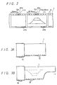
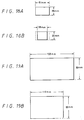
- a 35-mm photographic film 1 that can be used in a 35-mm photographic camera according to the present invention is described with reference to Figs. 1, 2, 3A, and 3B, in which Figs. 1 and 2 show 35-mm photographic film 1 after it has been exposed, and Figs. 3A and 3B show 35-mm photographic film 1 before being exposed.
- the 35-mm photographic film 1 is stored in a film cartridge 16 and has an end extending out of the film cartridge 16. Images that are photographed on the 35-mm photographic film 1 are turned upside down by the lenses, so that the upper end of an image is positioned on a lower portion of the photographic film 1.
- Fig. 3B shows by way of example a photographed image of a subject in broken lines, which appears to be turned upside down on the photographic film 1.
- Each of the photographic films 1 shown in Figs. 1, 2, 3A, and 3B has a series of film position detecting holes 19 defined along an unexposed marginal edge area thereof, which has a width of about 2.5 mm. This unexposed marginal area is used to control the film, to magnetically or optically read or write data, and when taking a picture.
- the film position detecting holes 19 have a diameter of about 1 mm and are spaced at a constant, predetermined pitch.
- the pitch of the film position detecting holes 19 in the photographic film 1 shown in Fig. 1 is 5.25 mm, for example, and the pitch of the film position detecting holes 19 in the photographic film 1 shown in Fig. 2 is 6.28 mm.
- the film position detecting holes 19 can be replaced by magnetic marks 19' spaced at a predetermined constant pitch and made by a suitable magnetic head on a magnetic edge portion 19" formed on the unexposed film.
- the magnetic marks 19' are shown as broken lines on the magnetic strip 19" in Figs. 4A and 4B, because they are not actually visable.
- the marks 19' could be formed as small dots of magnetic material, such as iron oxide or a transparent magnetic material, deposited on the unexposed film and detected by the magnetic head.
- the other side of the marginal area that is defined by holes 19 or magnetic marks 19', 19", as shown in Figs. 1-4, can be used for an order information area as described below. This order information area is recorded by the photographic image system and used in the photographic and video printing system.
- the photographic film 1 shown in Fig. 3A has film position detecting holes 19 that will be positioned along an upper marginal edge area after the photographic film is exposed, however, no tongue is provided at the leading end, so that no tongue-removing process will subsequently be required. Because no tongue-removing process will be required, the subsequent processing of the photographic film 1 is less costly. This applies to the film shown in Fig. 4A as well.
- the photographic film 1 shown in Fig. 3B also has film position detecting holes 19 that will be positioned in an upper marginal edge area thereof after the photographic film is exposed, and has a tongue at its leading end on its lower portion.
- the tongue at the leading end of the photographic film 1 is vertically opposite in position to the tongue of an ordinary 35-mm photographic film that is now generally commercially available. If a photocoupler is used in a photographic camera for detecting the film position detecting holes 19, then when the photographic film 1 is loaded into the photographic camera, the marginal edge with the film position detecting holes 19 is not required to be manually inserted into the photocoupler, but is automatically inserted into the photocoupler when the photographic film 1 is wound by a film transport mechanism in the photographic camera. This also applies to the film shown in Fig. 4B.
- FIG. 5 is a rear elevation of the photographic camera with the rear lid or cover removed.
- the lid is shown in Fig. 6.
- the photographic camera has a dark box 4 including a cartridge housing 17 for housing the film cartridge 16, which is of a known structure, an exposure opening 7 near the cartridge housing 17 and through which the photographic film 1 can be exposed to light passing through a camera lens, aperture, and shutter not shown in Fig. 5, and a film housing 18 for housing the photographic film 1 after it has been exposed.
- the photographic film 1 that is unwound from the film cartridge 16 housed in the cartridge housing 17 is fed over the exposure opening 7 while being transversely limited in motion by upper and lower respective pairs of film guides 30, 31, and is then moved into the film housing 18 after being exposed.
- the film housing 18 has a guide roller 32 for automatically setting or loading the photographic film 1, and a film take-up spool 9 rotatable by a motor, shown at 10 in Fig. 8, for winding the exposed photographic film 1 thereon.
- the photographic camera has a light-emitting diode (LED) 5a positioned between the lower film guides 30, 31 for detecting the film position detecting holes 19, and a photodetector, shown in Fig. 6 at 5b, disposed on a pressure plate of the rear lid and positioned in registry with the LED 5a across the photographic film 1.
- the photodetector 5b has a diameter of 1.5 mm, for example.
- the LED 5a emits infrared radiation having a wavelength of 940 nm, which is different from those radiation wavelengths to which the photographic film 1 is sensitive.
- the LED 5a and the photodetector 5b jointly make up a hole sensor 5 that applies an output signal to a counter in a system controller 8 that comprises a microcomputer. In this way, the system controller 8 can recognize the position of the photographic film 1 over the exposure opening 7.
- the LED 5a and the photodetector 5b may be alternatively replaced with a photocoupler that also comprises an LED and a photodetector but which are positioned in confronting relationship, as described hereinbelow.
- the exposure area opening 7 has its size defined by left and right movable masks 15 that are laterally movable over the width of the exposure opening 7 from opposite sides thereof.
- the size of the exposure opening 7 in the longitudinal direction of the photographic film 1 can selectively be changed to four different dimensions of 53.33 mm, 40.00 mm, 22.5 mm, and 16.90 mm as indicated by the four pairs of broken lines in Fig. 5.
- the left and right movable masks 15 are retractable into left and right side walls, respectively, that are positioned on opposite sides of the exposure opening 7 and extend substantially perpendicularly to the photographic film 1 as it extends over the exposure opening 7.
- two linear toothed bars 33 are attached to the respective lower edges of the movable masks 15 and held in mesh with respective drive feed gears 34 of a gearbox 35, much like a rack and pinion assembly.
- gears 34 of the gearbox 35 are driven to rotate the linear toothed bars 33, and hence the movable masks 15, are linearly moved over the exposure opening 7.
- the photographic camera has a frame size setting switch 6 which can manually be turned by the user of the camera to produce a command signal indicative of a selected frame size which is one of the frame sizes described above in Table 1.
- the frame size setting switch 6 applies a command signal to the system controller 8, which then supplies a control signal to achieve the desired frame size through a stepping motor driving circuit 13 to a stepping motor 14.
- the stepping motor 14 is energized to rotate the feed gears 34 to move the movable masks 15.
- the hole sensor 5 produces and supplies a detected film position signal to the system controller 8, which processes the supplied film position signal to generate a control signal.
- the system controller 8 then supplies the control signal through an amplifier 36 to a motor 10, which rotates the film spool 9 to take-up the photographic film 1 over a predetermined length.
- the length over which the photographic film 1 is driven corresponds to the distance that is determined by the frame size setting switch 6.
- the feeding of the photographic film 1 is described below with reference to Figs. 11A through 11E, which show examples in which the hole pitch is 6.28 mm and the photographic film 1 is to be exposed in an HDTV-matched full-frame size of 30 mm x 53.3 mm and an NTSC-matched full-frame size of 30 mm x 40 mm.
- Fig. 11A shows a portion of the photographic film 1 as it is exposed in successive NTSC-matched full frames.
- the photographic film 1 is fed for seven pitches of the holes 19, a frame area of 30 mm x 40 mm is made available for exposure through the exposure opening 7.
- the photographic film 1 is fed for eight pitches of the holes 19, as shown in Fig. 11B, to make a frame area of 30 mm x 53.3 mm available for exposure through the exposure opening 7.
- the photographic film 1 is fed for nine pitches of the holes 19, as shown in Fig.
- the photographic film 1 is fed for eight pitches of the holes 19, as shown in Fig. 19D, to make a frame area of 30 mm x 40 mm available for exposure through the exposure opening 7.
- the system controller 8 controls the motor 10 as follows: When switching from an NTSC-matched full-frame size to an HDTV-matched full-frame size, the photographic film 1 is first driven for seven pitches of the holes 19 and is then driven for one additional hole pitch. When switching from an HDTV-matched full-frame size to an NTSC-matched full-frame size, the photographic film 1 is first driven forward for nine pitches of the holes 19 and is then driven backward for one pitch.
- the photographic film 1 When changing frame sizes, the photographic film 1 may be driven for a different distance or a different number of pitches, such as ten pitches of the holes 19, as shown in Fig. 11E. In this manner, the photographic film 1 may be easily exposed in many different frame sizes.
- the system controller of the photographic camera controls the feeding of the photographic film 1 such that the photographic film 1 will not be exposed in overlapping frames, even when different frame sizes are exposed.
- Figs. 1 and 2 illustrate the photographic film 1 whose effective exposure areas have been exposed in frames 3 of different sizes.
- the photographic film 1 has been exposed in an HDTV-matched full-frame size, having a width of 30 mm, a length of 53.3 mm, and aspect ratio of 9:16, and in an NTSC-matched full-frame size, having a width of 30 mm, a length of 40 mm) whose aspect ratio is 3 : 4.
- the holes 19 defined along the upper marginal edge of the photographic film 1 have a pitch of 5.25 mm.
- the photographic film 1 has also been exposed in an HDTV-matched full-frame size and an NTSC-matched full-frame size, however, unlike Fig. 1, the holes 19 defined in the upper marginal edge of the photographic film 1 have a pitch of 6.28 mm.
- one frame of an HDTV-matched full-frame size corresponds to nine pitches of the holes 19
- one frame of an NTSC-matched full-frame size corresponds to seven pitches of the holes 19. Since these pitches are odd-numbered, a hole 19 may be positioned in alignment with the center of the frame, so that the center of the frame can easily be detected.
- the photographic camera has a shutter release button 37.
- the system controller 8 controls the size of the exposure area and supplies a control signal to a mark recording circuit 38 for recording a central mark, a so-called effective exposure area position signal, indicative of the center of the frame 3 and also supplies a control signal to a frame number recording circuit 39 for recording a frame number.
- the mark recording circuit 38 energizes an LED 40 positioned at the lower film-guide pair 30, 31 for recording a central mark 40a, shown in Figs. 1 and 2, representing the center of the exposed frame 3.
- the frame number recording circuit 39 energizes an LED 41 positioned at the lower film guide pair 30, 31 for recording a frame number 41a, shown in Figs. 1 and 2, representing the frame number of the exposed frame 3.
- the frame number 41a can be recorded such that it agrees with an actual frame number.
- the system controller 8 also supplies a control signal to a frame size recording circuit 11 for recording a frame size signal, a so-called effective exposure area width signal, indicative of the frame size of the exposed frame 3.
- the frame size recording circuit 11 energizes an LED 12 positioned at the lower film guide pair 30, 31 for recording a frame size signal 12a, shown in Figs. 1 and 2.
- a magnetic head 12' in place of LED 12 a magnetic head 12' can be employed to record the frame size signal on the marginal area 19" on the unexposed film.
- the magnetic head 5c that senses the magnetic marks 19' on the film shown in Figs. 4A and 4B is connected to the system controller 8 through a buffer amplifier 5d or a similar playback amplifier.
- the LED 12 may be composed of four LED elements which are selectively energized to record one of the frame size signals 12a, which represent the frame size set by the frame size setting switch 6.
- the various frame size signals 12a are shown by way of example in Table 2 below.
- Table 2 Frame Size Frame size signal 12a HDTV-matched full-frame size
- the central mark 40a and the frame size signal 12a supply information regarding the frame position and the frame size to an automatic printer, described hereinbelow, for controlling the automatic printer when the exposed and processed film is printed.
- the photographic camera according to the present invention has a detecting means 5a, 5b for detecting the feeding of the photographic film 1, a film control system 8, 9, 10 for controlling the distance by which the photographic film 1 moves and for driving the photographic film 1 for a length corresponding to the width of the selected exposure opening 7, based on a detected signal from the detecting means 5a, 5b, and for controlling a signal recording device 8, 11, 12, 38, 40 disposed near the exposure opening 7 for recording a signal indicative of the position of the exposure opening 7 on the photographic film 1 when the photographic film 1 is exposed through the exposure opening 7.
- the processed photographic film 1 After the photographic film 1 is exposed using the photographic camera, the processed photographic film 1 bears control signals that are recorded in a signal recording area 21, shown in see Fig. 1, thereof and that will be used when the photographic film 1 is printed. Therefore, even if the developed photographic film 1 contains frames of different frame sizes, it can be automatically printed by an automatic printer without requiring individual adjustment.
- the photographic camera according to the present invention also has a film control system 8, 9, 10 for controlling the feeding or driving of the photographic film 1, and an opening control system 8, 13, 14, 15 for varying the width of the exposure opening 7 along the photographic film 1. At least when the width of the exposure opening 7 changes from a smaller dimension to a larger dimension, the film control system 8, 9, 10 drives the photographic film 1 for a length corresponding to the selected width of the exposure opening 7.
- the width of the exposure opening 7 is variable, and the take-up or driving of the photographic film 1 is controlled depending on the width of the exposure opening 7.
- the photographic camera can expose the photographic film 1 successively in desired frame sizes which may differ one from another without adjacent frames overlapping each other.
- the photographic film 1 used in the photographic camera according to the present invention has a signal recording area 21 located between an effective exposure area 20 and a marginal edge thereof for magnetically or optically recording control signals, which will be used when the photographic film 1 is processed and printed.
- the film 1 has holes 19 or magnetic marks 19' defined in an upper marginal edge area thereof between the effective exposure area 20 and the marginal edge for detecting the distance by which the photographic film 1 has been moved.
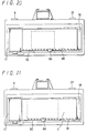
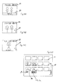
- an automatic printer for automatically printing processed photographic film 1 that has been exposed using a camera as described above has a printer body that supports a paper supply reel 45 for supplying the sensitized print paper 46, a paper deck or platen 47 for supporting the print paper 46 supplied from the paper supply reel 45, a variable paper mask 48 for determining the size of a print paper segment on which an image is to be printed, a paper holder plate 49 for holding the print paper 46 down against the paper deck 47, a paper feed or drive roller 50 for driving the print paper 46, and a paper takeup reel 51 for winding the exposed print paper 46.
- the printer body of the automatic printer also supports a film supply reel 52 for supplying the processed photographic film 1, a film deck or platen 53 for supporting the photographic film 1 supplied from the film supply reel 52, a negative-carrier variable slit 54, a negative holder plate 55 for positioning the negative down against the film deck 53, a film feed or drive roller 56 for driving the photographic film 1, a film takeup reel 57 for winding the exposed and processed photographic film 1, a lens 58 positioned above the negative holder plate 55, a bellows 59 supporting the lens 58 and positioned below the paper deck 47, a lamp 60 disposed below the film deck 53, a black shutter 61 positioned above the lamp 60, a filter assembly 62 composed of yellow, magenta, and cyan (Y, M, C) filters, and a diffusion box 63 disposed between the filter assembly 62 and the film deck 53.
- a film supply reel 52 for supplying the processed photographic film 1
- a film deck or platen 53 for supporting the photographic film 1 supplied from the film supply reel 52
- the negative holder plate 55 supports a frame size sensor S1 for detecting the frame size signal 12a recorded on the photographic film 1, a frame center sensor S2 for detecting the central mark 40a recorded on the photographic film 1 that indicates the center of a frame, and an order sensor S3 for magnetically detecting order information about a print size and number of prints being ordered.
- This order information is recorded in the other marginal area opposite the one defined by the holes 19 or magnetic marks 19', 19", as shown in Figs. 1-4.
- the film drive roller 56 Upon detection of the central mark 40a of the frame 3 with the frame center sensor S2, the film drive roller 56 is controlled to drive the film to align the frame center with the center of the negative-carrier variable slit 54.
- the variable paper mask 48 and the negative-carrier variable slit 54 are controlled based on the frame size signal 12a that is detected by the frame size sensor S1.
- FIG. 14 A control system for the automatic printer is shown in Fig. 14, in which the frame size sensor S1 and the frame center sensor S2 comprise photocouplers, respectively, for detecting the frame size signal 12a and the central mark 40a, respectively, that are recorded in the marginal edge area of the photographic film 1.
- the optical sensors S1 and S2 may be comprised of respective magnetic heads S1' and S2', as shown in Fig. 15, that read the frame size signal and the frame center signal that are magnetically recorded on the marginal area 19" of the unexposed film.
- the frame center is determined based on the central mark 40a detected by the frame center sensor S2, and the frame size of the frame 3 whose frame center is determined by a microprocessor 64 of the control system based on the frame size signal 12a that is read by the frame size sensor S1 before the central mark 40a is detected by the frame center sensor S2. Then, the microprocessor 64 controls a mask size drive motor M3 to actuate the variable paper mask 48 to conform with the determined frame size. At the same time, the microprocessor 64 controls a negative-carrier variable slit drive motor M2 to actuate the negative-carrier variable slit 54.
- the microprocessor 64 controls a film feed motor M1 to rotate the film feed roller 56 for feeding the photographic film 1 for a predetermined length.
- the microprocessor 64 controls a paper feed motor M4 to rotate the paper feed roller 50 for thereby feeding the print paper 46 for a predetermined length.
- the microprocessor 64 controls the number of prints and changes the size of the image on the sensitized print paper.
- This paper change system may be comprised of a paper feed mechanism and an optical selecting instrument, which are not shown. In such a system the optical selecting instrument selects a corresponding paper feed mechanism operation in response to the print size signal.
- Figs. 16A and 16B show the relationship between the photographic film 1, the frame center sensor S2, and the frame size sensor S1 in the automatic printer.
- a frame size indicator 12a is detected by the frame size sensor S1 before its frame 3 is positioned and the sensor S1 output signal is used for controlling the driving of the photographic film 1, the negative-carrier variable slit 54, and the variable paper mask 48.
- the frame size signal from sensor S1 is processed by the microprocessor 64, which determines the frame size when the frame center of the frame 3 is determined by the frame center sensor S2.
- the central mark 40A indicative of a frame center is recorded at each frame on the photographic film 1.
- the frame size indicator 12a is recorded ahead of the central mark 40a
- the frame number 41a is recorded behind the central mark 40a with respect to the direction in which the photographic film 1 is driven.
- frame center sensor S2 and the frame size sensor S1 are shown as being located in substantially the same position, only the frame center sensor S2 should be positioned in alignment with the center of the negative-carrier variable slit 54 and the variable paper mask 48, and the frame size sensor S1 may be positioned on the film deck 53 at the entrance end thereof. This applies to the magnetic head sensors S1' and S2' as well.
- Fig. 17 shows a control sequence of the microprocessor 64 for controlling the driving of the developed photographic film or negative 1 and the driving of the print paper 46.
- the negative-carrier variable slit 54 and the variable paper mask 48 are also controlled in this control sequence.
- the photographic film 1 is continuously driven and taken up until the central mark 40a is detected by the frame center sensor S2, and then the photographic film 1 is stopped when the central mark 40a is detected by the frame center sensor S2. Until the photographic film 1 is stopped, the frame size indicator 12a is detected by the frame size sensor S1 and its number is counted.
- the width of the negative-carrier variable slit 54 is set to 38 mm, and the width of the variable paper mask 48 is set to 119 mm.
- the print paper 46 is moved, and the photographic film 1 is printed, after which the control sequence is ended.
- the print paper 46 is moved for a distance corresponding to printed frame sizes, a blank surrounding the printed frames, and a cutting blank between the printed frames.
- a hole is defined in the cutting blank when the photographic film 1 is printed, and serves as a positional signal for automatically cutting the print paper.
- the width of the negative-carrier variable slit 54 is set to 51 mm, and the width of the variable paper mask 48 is set to 158 mm. Thereafter, the print paper 46 is moved, and the photographic film 1 is printed, after which the control sequence is ended.
- the frame size indicator 12a represents "1" or "2"
- the widths of the negative-carrier variable slit 54 and the variable paper mask 48 are set similarly. Thereafter, the print paper 46 is moved, and the photographic film 1 is printed, after which the control sequence is ended.
- the frame size indicator 12a is recorded in the upper marginal edge portion of the photographic film 1, it may possibly be recognized in error as the central mark 40a.
- a negative feed sensor S3, shown in Fig. 14, for detecting the distance by which the photographic film 1 is fed is associated with the film feed motor M1, and the distance by which the photographic film 1 is fed is measured by a counter 65 whose count is fed back to the microprocessor 64. Since the width of the frame size indicator 12a on the photographic film 1 can be detected by the distance by which the photographic film 1 is driven, the frame size indicator 12a can be distinguished from the central mark 40a or the frame number 41a.
- the automatic printer according to the present invention has a film drive control device 65, 64, M1 for detecting an effective exposure area position indicator 40a recorded in a marginal edge area between the effective exposure area 20 on the photographic film 1 and the marginal edge thereof to control the driving of the photographic film 1, and a printing opening width control device 54, 64, M2 for detecting an effective exposure area width indicator 12a recorded in the marginal edge area to control the width of the printing opening along the photographic film 1.
- the photographic film 1 has an effective exposure area position indicator 40a and an effective exposure area width indicator 12a which are recorded in a marginal edge area between the effective exposure area 20 on the photographic film 1 and the marginal edge thereof. After the effective exposure area width indicator 12a has been detected, the effective exposure area position indicator 40a is detected. The width of the film exposure opening along the photographic film 1, the width of the print paper exposure opening, and the distance by which the print paper 46 is driven are controlled based on the detected effective exposure area width indicator 12a, and the distance by which the photographic film 1 is fed is controlled based on the detected effective exposure area position indicator 40a.
- the photographic film 1 can automatically be printed even if it has a succession of frames of different sizes.
- a photocoupler 66 which is an integral combination of an LED and a photodetector for detecting a film position, may be disposed on a film guide 30.
- the photocoupler 66 may be positioned anywhere on the film guide 30.
- the photocoupler 66 may have LEDs 41, 40, as shown in Fig. 5, for recording the frame number 41a and the central mark 40a at the same time that the frame is exposed.
- the hole sensor 5 comprises an LED and a photodetector in the illustrated photographic camera
- the hole sensor 5 may comprise two pairs of an LED and a photodetector given the different distances by which frames of different sizes are fed.
- the same photographic film contain frames of different sizes, however, the present invention is also applicable to an automatic printer for automatically printing a spliced length of photographic films with different frame sizes.
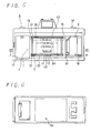
- FIG. 70 An embodiment of a photographic image system 70 that can transform an image in a frame on the photographic film 1 to a video signal is shown and described in regard to Figs. 22 through 30.
- This embodiment uses a printing order system which permits communication between the camera user and the processing laboratories.
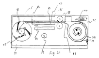
- Fig. 22 is a perspective view of the photographic image system 70 having an upper body 71 and a lower body 72.
- the upper body 71 has a print select panel 85 on a front surface that is described below, as well as a power display panel 84, and includes an optical instrument, a charge coupled device, and the necessary drive circuits.
- the lower body 72 has a display adjusting panel 73, a film cartridge housing 79 and a window 81, and includes a lamp 89 and a film feed mechanism 88, as shown in Fig. 23.
- the display adjusting panel 73 has a color adjusting switch 74, a zoom control switch 75, a focus control switch 76, an iris control switch 77, and a main power indicator lamp 78. These switches 74 through 77 are manually used for adjusting the quality of the display image.
- the main power switch 80 is on the back right side of the lower body 72.
- a processed film cartridge 86 is accommodated in the film cartridge housing 79, and a processed film 1 is drawn out from the cartridge 86 and is guided by a film guide 92.
- the processed photographic film 1 is fed from the film cartridge housing 79 to a film housing 87 by the film feed mechanism 88.
- This film feed mechanism 88 includes driven roller pairs and idler roller pairs as well as a take-up reel mechanism and automatically feeds a film by detecting a frame position signal recorded on the film or by detecting holes placed in the film, as shown in Figs. 16A and 16B.
- the processed photographic film is illuminated by the lamp 89 through the diffuse filter 90.
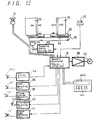
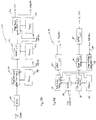
- the film feed mechanism 88 is driven by a motor 93 that is controlled by a film driving circuit 94 and a system controller 95, shown in Fig. 24.
- This system controller 95 controls the film feeding and film image transformation for transforming an image of the processed photographic film to a video signal.
- the system controller 95 detects the frame size signals 12a and frame center marks 40a using detectors 155, 156 and a hole/center mark detecting circuit 115.
- the frame center marks 40a may replace a hole 19 formed in a marginal edge of the photographic film.
- an image of the processed photographic film is projected on a charge coupled device 96 through an objective lens 97, a zoom lens 98, a focus lens 99, and a diaphragm 100.
- These lenses and the diaphragm are driven by a zoom motor 101, a focus motor 102, and a diaphragm or iris motor 103, respectively.
- These motors are respectively controlled by a zoom motor circuit 104, a focus motor circuit 105, an iris motor circuit 106, and the system controller 95.
- the system controller 95 controls the diaphragm 100 in response to the magnification selected for the zoom lens 98.
- the image of the processed photographic film is projected on an image transform area 107 of the charge coupled device 96.
- the actual extent of this area is selected by the system controller 95 in response to a frame size signal 12a detected by the detector 94 and frame size signal detecting circuits 155, 156.
- Area sizes C through F correspond respectively to NTSC-matched frame size (half size), HDTV-matched frame size (half size), NTSC-matched frame size (full size), and HDTV-matched frame size (full size), and area sizes A and B may be selected by a full or panorama size signal in response to a user request or the frame size signal 12a recorded by a photographic camera.
- FIG. 26 Another embodiment of the image area selecting system is illustrated in Fig. 26.
- the zoom lens 98 enlarges a NTSC-matched frame 108 size (full size) on the HDTV size area of the CCD image transform area 107.
- the enlarged NTSC-matched frame loses a part of the image but all pixels of the CCD image transform area 107 are effectively used.
- a portion 107A of the CCD image transform area is used to transform information, such as the user entered information 43a, in the marginal area of the photographic film to a video signal as shown in Figs. 28 and 30A.
- the system controller 95 controls an image signal process circuit 110 in response to an image signal detected by the charge coupled device 96 and in response to a frame size signal 12a.
- the image signal process circuit 110 generates an HDTV video signal or an NTSC video signal and other signals as well. These signal outputs are fed to a monitor or television 170, as shown in Fig. 27.
- the photographic image system 70 is controlled by a remote controller 116.
- This remote controller 116 controls feeding of the film, the display size, and the printing order.
- the system controller 95 controls the image signal process circuit 110 to mix or insert a graphical order menu 171 onto the image obtained from the processed photographic film.
- This printing order is recorded on a magnetic area of the processed film by a magnetic head 112 and a signal detect/recording circuit 113, as shown in Fig. 24.
- the print select panel 85 has an automatic mode select switch 117, and when this select switch is turned off, the user can manually control the operations by using switches 118 through 121. These switches 118-121 can manually control the zoom motor driving circuit 104, the focus motor driving circuit 105, and the iris motor driving circuit 106, respectively.
- a switch 122 selects a transform of the image signal process circuit which transforms a positive or negative image of the processed photographic film to a black-white or color video signal.
- a switch 123 selects an order menu or an ordinary display.
- a switch 128 selects the size of the photographic print that will be produced. Such sizes can be a service size, a cabinet size, a quarter size or some other size.
- a display 127 displays the selected size of the print paper, and a display 129 displays the number of the frame.
- the displays 126, 124 and 127 display the size or aspect of the frame, the number of prints ordered, and the print size of the paper, respectively.
- a first step A is an ordinary mode, which displays a film size 172 and the frame number 173 of the photographic film.
- a second step B is an order confirmation menu 174.
- a third step C is an order menu that displays a print size 175, number of prints 176, and a final confirmation of the order 177.
- This menu 171 is also controlled by the remote controller 116.
- the remote controller 116 has an order button 130 that selects an order situation menu, which is the second step B in Fig. 28. If a yes menu is selected by a yes button or a cursor switch 132 of the remote controller 116 in the second step B, the menu process jumps to the third step C. The cursor is then used to select the print size, the number of prints, and a final confirmation of the order.
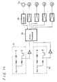
- the image signal process circuit 110 includes a digital converstion circuit and an image process circuit and output circuit, as shown in Fig. 29A.
- the conversion circuit has an analog to digital converter 139 for converting a CCD output signal, as shown in Fig. 24, or the output a line sensor of a flat-bed type scanner, as shown in Figs. 31a and 31b, into a digital signal.
- Output data of this analog to digital converter 139 are RGB digital data.
- This RGB data is corrected and converted by a brightness correction and color converting circuit 140.
- This circuit uses correction data and color converting data from a memory 141.
- the correction data is used to correct any transform deviations between various RGB detectors.
- the color converting data are for transforming from RGB data to CM data, which is data for transforming between positive-film and negative film and data for selecting a color image or black/white image.
- the transformation between positive-film and negative film and a selection of a color image or a black/white image are selected by the switch 122 shown in Fig. 24, and the select data are sent through a data bus 138 from the system controller 95 to the image signal process circuit 110.
- the data bus sends control data for the brightness correct and color converting circuit 140 and for a film-type correction circuit 142.
- the transformed data from the brightness correct and color converting circuit 140 is fed to the next correction circuit 142.
- This correction circuit 142 corrects a film sensitivity deviation for each film type by using sensitivity correcting data from a memory 143 and is controlled by the system controller 95.
- the system controller 95 detects the film type using the detector 160 disposed at the processed film cartridge housing 79.
- This film type detector 160 shown in Fig. 23 and a film type detecting circuit 161 shown in Fig. 24 detect the film type data that is magnetically or optically recorded on the film cartridge and send a film type data signal to the system controller 95.
- This detector 160 could also detect magnetic or optical data on the film, in which case it would be disposed on the film guide 92.
- the CM data for correcting the film sensitivity deviation are fed to an image process and output circuit 144.
- this circuit 144 corrects a CRT deviation and adjusts a CRT display size and, on the other hand, the circuit 144 converts the CM data to RGB data or to a composite video signal for a CRT display and superimposes the control data from the system controller 95 on the RGB data or the composite video signal.
- This circuit 144 also adjusts an image size of the CM data corresponding to the frame size signal 12a and outputs signals to a computer system or a disc drive control circuit.
- this image process and output circuit 144 comprises two operational circuits.
- a first operational circuit outputs bit-map type data to the outer computer and comprises a transfer circuit 160, a data hold/process circuit 161, and a computer output circuit 162.
- This bit-map type data may be replaced by GIF type data, TIFF type data, or some other type data.
- the transfer circuit 160 receives the CM data for correcting the film sensitivity deviation and transfers the data to the hold/process circuit 161 and to a CRT deviation correct circuit 163.
- the data/hold process circuit 161 receives the CM data and transforms the data type, the data size, and a display size.
- the data type is selected from the bit-map type, the GIF type data, the TIFF type data, JPEG type data, or some other type data by the image controller/superimpose circuit 166.
- the data size and the display size are selected by the image controller/superimpose circuit 166 according to the detected frame size signal 12a.
- the CM data, processed and transformed as to data type, data size, and display size are held and transferred to the output circuit 162.
- the transfer circuit 160 is also included in the second operational circuit.
- This second operational circuit is for outputting RGB data or a composite video signal to the CRT, LCD, or other display device and comprises the transfer circuit 160, the CRT deviation correction circuit 163, an image hold/process circuit 164, and a CRT output circuit 165. These block are controlled by an image controller/superimpose circuit 166 and processes using data from the memory 165.
- the CRT deviation correction circuit 163 corrects the CRT deviation using the CRT deviation data from the memory 165 and transforms the CM Data into RGB data.
- the image hold/process circuit 164 receives the RGB data and processes an image superimposition onto the RGB data.
- the RGB data is controlled and adjusted to a display size by the image controller/superimpose circuit 166 according to the detected frame size signal 12a.
- the display data for superimposition are the film size 172, a number of the frame 173, and the order number information 176, as shown in Fig. 28.
- the image hold/process circuit 164 has two image planes. One image plane holds the RGB data and other image plane holds the superimpose data. These two image plane data are transferred to the output circuit 165 where they are mixed or superimposed with each other and transferred as RGB data or as a composite video signal.
- Figs. 30A through 30D illustrates such an image superimposition.
- an image of the photographic film can be selectively enlarged.
- the display data for film size 171, the number of the frame 173 and other data is superimposed on the image.
- Fig. 30D shows order confirmation windows by use by the operation in confirming the order information. This menu is displayed after the graphical menu 171 of the order as shown Fig. 28.
- twelve windows are displayed corresponding to twelve exposures on the film. Each window continuously displays each frame of the processed photographic film 1.
- a display area below each window displays order information, such as print size 175 and the number 176 of prints to be made.
- the processed film 1 is driven by the film driving motor and illuminated by the lamp 89 and the diffuse filter 90.
- a glass window 81, the lamp 89, and the diffuse filter 90 are disposed in the lower body 72 of the photographic and video imaging system 70.
- the detectors 155, 156 for detecting a frame size 12a and a frame mark 40a and the recording/writing head 112 are disposed on opposite sides of the film 1 from the window 81.
- the frame center mark 40a may be replaced by a hole 19.
- the line sensor 96' and a lens 148 are disposed on a slider 149.
- the slider 149 is driven along a position rod 152 by a motor 150 and a belt 151.
- the above two embodiments of the photographic image system relate to an automatic printer in which the photosensitive paper is replaced by a CCD.
- These two embodiments use an exposure control signal magnetically or optically recorded between an edge of the photographic film and an effective exposure area of the photographic film.
- These embodiments use the same position on the film for an order information area as in the previously explained embodiment, and this order information area is used by the automatic printer system at the time the photographic prints are made.
- the exposure control signal can be used not only by the processor but also by the user, and the user can print by a simple printer system according to the present invention.
- Such a home printing system can be combined with a computer system or a television for display.
- the present invention uses an exposure control signal magnetically or optically recorded between an edge of the photographic film and an effective exposure area of the photographic film.
- This signal can be used not only by the processor but also by the individual user, so that the individual can print using a relatively simple printer system according to the present invention.
- This simple home system can be combined with a computer system or a television for display.
- an exposure control signal of the present invention may include an auxiliary signal for controlling a printer system or indicating certain features to the user.
- the present invention as described above can be used for many applications because it avoids using the punched in notch required in previously proposed systems.
- the aspect information or effective exposure size signal is the frame size signal 12a which is indicative of the size of its associated frame on the photographic film.
- the camera could be used to make images on the film with frames of the same size but with the aspect information or effective exposure size signal being a print signal indicative of the (user) desired print size or print aspect ratio.
- the printer or video transfer device would then operate in very similar manners to those described above, with different image sizes being produced according to the detected print signal. The main difference would be that, according to the print signals, different parts of the frames would not be printed/transferred, as they would not fit into the desired size or aspect ratio.
Priority Applications (7)
| Application Number | Priority Date | Filing Date | Title |
|---|---|---|---|
| EP00122965A EP1076258B1 (de) | 1995-05-22 | 1996-05-16 | Fotografisches Kopiergerät mit anpassbarer Maske |
| EP00122971A EP1094356A1 (de) | 1995-05-22 | 1996-05-16 | Multiformat-Kamera, die Bildgrösse-Information auf den Film aufzeichnet, sowie photographischer Printer und Vorrichtung zur Videokonversion photographischer Bilder |
| EP00122964A EP1076260B1 (de) | 1995-05-22 | 1996-05-16 | Vorrichtung zum Aufzeichnen von Bestellungsdaten auf einem photographischen Film |
| EP00122979A EP1094358B1 (de) | 1995-05-22 | 1996-05-16 | Vorrichtung und Verfahren zur Konversion photographischer Bilder in Videosignale, und um Druckaufträge auf dem Film aufzuzeichnen |
| EP05007641A EP1553442A1 (de) | 1995-05-22 | 1996-05-16 | Vorrichtung zur Konversion photographischer Bilder in Bildsignalen |
| DE29624246U DE29624246U1 (de) | 1995-05-22 | 1996-05-16 | Fotografische Bildvorrichtung |
| EP00122978A EP1094357A1 (de) | 1995-05-22 | 1996-05-16 | Kamera, die Bildgrösse-Information auf den Film aufzeichnet, und Vorrichtung zur Konversion photographischer Bilder in Bildsignalen |
Applications Claiming Priority (2)
| Application Number | Priority Date | Filing Date | Title |
|---|---|---|---|
| US445772 | 1995-05-22 | ||
| US08/445,772 US5652643A (en) | 1992-03-17 | 1995-05-22 | Photographic and video image system |
Related Child Applications (5)
| Application Number | Title | Priority Date | Filing Date |
|---|---|---|---|
| EP00122971A Division EP1094356A1 (de) | 1995-05-22 | 1996-05-16 | Multiformat-Kamera, die Bildgrösse-Information auf den Film aufzeichnet, sowie photographischer Printer und Vorrichtung zur Videokonversion photographischer Bilder |
| EP00122964A Division EP1076260B1 (de) | 1995-05-22 | 1996-05-16 | Vorrichtung zum Aufzeichnen von Bestellungsdaten auf einem photographischen Film |
| EP00122965A Division EP1076258B1 (de) | 1995-05-22 | 1996-05-16 | Fotografisches Kopiergerät mit anpassbarer Maske |
| EP00122978A Division EP1094357A1 (de) | 1995-05-22 | 1996-05-16 | Kamera, die Bildgrösse-Information auf den Film aufzeichnet, und Vorrichtung zur Konversion photographischer Bilder in Bildsignalen |
| EP00122979A Division EP1094358B1 (de) | 1995-05-22 | 1996-05-16 | Vorrichtung und Verfahren zur Konversion photographischer Bilder in Videosignale, und um Druckaufträge auf dem Film aufzuzeichnen |
Publications (3)
| Publication Number | Publication Date |
|---|---|
| EP0744651A2 true EP0744651A2 (de) | 1996-11-27 |
| EP0744651A3 EP0744651A3 (de) | 1998-09-30 |
| EP0744651B1 EP0744651B1 (de) | 2002-08-07 |
Family
ID=23770134
Family Applications (7)
| Application Number | Title | Priority Date | Filing Date |
|---|---|---|---|
| EP00122971A Withdrawn EP1094356A1 (de) | 1995-05-22 | 1996-05-16 | Multiformat-Kamera, die Bildgrösse-Information auf den Film aufzeichnet, sowie photographischer Printer und Vorrichtung zur Videokonversion photographischer Bilder |
| EP96303473A Expired - Lifetime EP0744651B1 (de) | 1995-05-22 | 1996-05-16 | Multiformat-Kamera, die Bildgrösse-Information auf den Film aufzeichnet, sowie photographischer Printer und Vorrichtung zur Videokonversion photographischer Bilder |
| EP00122978A Ceased EP1094357A1 (de) | 1995-05-22 | 1996-05-16 | Kamera, die Bildgrösse-Information auf den Film aufzeichnet, und Vorrichtung zur Konversion photographischer Bilder in Bildsignalen |
| EP00122979A Expired - Lifetime EP1094358B1 (de) | 1995-05-22 | 1996-05-16 | Vorrichtung und Verfahren zur Konversion photographischer Bilder in Videosignale, und um Druckaufträge auf dem Film aufzuzeichnen |
| EP00122965A Expired - Lifetime EP1076258B1 (de) | 1995-05-22 | 1996-05-16 | Fotografisches Kopiergerät mit anpassbarer Maske |
| EP05007641A Ceased EP1553442A1 (de) | 1995-05-22 | 1996-05-16 | Vorrichtung zur Konversion photographischer Bilder in Bildsignalen |
| EP00122964A Expired - Lifetime EP1076260B1 (de) | 1995-05-22 | 1996-05-16 | Vorrichtung zum Aufzeichnen von Bestellungsdaten auf einem photographischen Film |
Family Applications Before (1)
| Application Number | Title | Priority Date | Filing Date |
|---|---|---|---|
| EP00122971A Withdrawn EP1094356A1 (de) | 1995-05-22 | 1996-05-16 | Multiformat-Kamera, die Bildgrösse-Information auf den Film aufzeichnet, sowie photographischer Printer und Vorrichtung zur Videokonversion photographischer Bilder |
Family Applications After (5)
| Application Number | Title | Priority Date | Filing Date |
|---|---|---|---|
| EP00122978A Ceased EP1094357A1 (de) | 1995-05-22 | 1996-05-16 | Kamera, die Bildgrösse-Information auf den Film aufzeichnet, und Vorrichtung zur Konversion photographischer Bilder in Bildsignalen |
| EP00122979A Expired - Lifetime EP1094358B1 (de) | 1995-05-22 | 1996-05-16 | Vorrichtung und Verfahren zur Konversion photographischer Bilder in Videosignale, und um Druckaufträge auf dem Film aufzuzeichnen |
| EP00122965A Expired - Lifetime EP1076258B1 (de) | 1995-05-22 | 1996-05-16 | Fotografisches Kopiergerät mit anpassbarer Maske |
| EP05007641A Ceased EP1553442A1 (de) | 1995-05-22 | 1996-05-16 | Vorrichtung zur Konversion photographischer Bilder in Bildsignalen |
| EP00122964A Expired - Lifetime EP1076260B1 (de) | 1995-05-22 | 1996-05-16 | Vorrichtung zum Aufzeichnen von Bestellungsdaten auf einem photographischen Film |
Country Status (11)
| Country | Link |
|---|---|
| US (8) | US5652643A (de) |
| EP (7) | EP1094356A1 (de) |
| JP (2) | JP3726348B2 (de) |
| KR (2) | KR100438224B1 (de) |
| CN (6) | CN1485690A (de) |
| AU (1) | AU716058B2 (de) |
| CA (1) | CA2175874C (de) |
| DE (4) | DE69633878T2 (de) |
| ES (4) | ES2226680T3 (de) |
| HK (1) | HK1037739A1 (de) |
| TW (1) | TW311991B (de) |
Cited By (5)
| Publication number | Priority date | Publication date | Assignee | Title |
|---|---|---|---|---|
| EP0878730A1 (de) * | 1997-05-16 | 1998-11-18 | Eastman Kodak Company | APS Formatwähler |
| EP0977084A1 (de) * | 1998-07-31 | 2000-02-02 | Eastman Kodak Company | Verfahren und Vorrichtung zur Verarbeitung von Kundenbildern |
| EP1107566A2 (de) * | 1999-12-08 | 2001-06-13 | Eastman Kodak Company | System und Verfahren zum Verarbeiten und/oder Manipulieren von Bilder |
| EP1538820A2 (de) * | 2003-12-04 | 2005-06-08 | Sony Corporation | Drucksystem und Druckverfahren |
| FR2867342A1 (fr) * | 2004-03-03 | 2005-09-09 | Eastman Kodak Co | Procede de conservation d'images |
Families Citing this family (38)
| Publication number | Priority date | Publication date | Assignee | Title |
|---|---|---|---|---|
| US5752114A (en) | 1992-03-17 | 1998-05-12 | Sony Corporation | Photographic and video image system |
| US6115558A (en) * | 1992-03-17 | 2000-09-05 | Sony Corporation | Photographic camera system |
| EP0843200A3 (de) * | 1992-03-17 | 1998-11-04 | Sony Corporation | Photographischer Kamera |
| US5570147A (en) | 1992-03-17 | 1996-10-29 | Sony Corporation | Photographic camera system |
| US6583851B2 (en) | 1992-03-17 | 2003-06-24 | Sony Corporation | Photographic and video image system |
| US6151456A (en) | 1993-03-04 | 2000-11-21 | Sony Corporation | Photographic camera system |
| US5652643A (en) | 1992-03-17 | 1997-07-29 | Sony Corporation | Photographic and video image system |
| US6470152B2 (en) | 1992-03-17 | 2002-10-22 | Sony Corporation | Photographic and video image system |
| US6600880B2 (en) | 1992-03-17 | 2003-07-29 | Sony Corporation | Photographic camera system |
| US6006042A (en) * | 1992-03-17 | 1999-12-21 | Sony Corporation | Photographic camera system |
| US6094217A (en) * | 1994-10-27 | 2000-07-25 | Fuji Photo Film Co., Ltd. | Automatic regenerating method for film image |
| JP3093607B2 (ja) * | 1995-06-01 | 2000-10-03 | キヤノン株式会社 | カメラ及びカメラのための装置 |
| JP3495826B2 (ja) * | 1995-08-24 | 2004-02-09 | 富士写真フイルム株式会社 | ファイリング・システムおよび再生装置 |
| US5668596A (en) | 1996-02-29 | 1997-09-16 | Eastman Kodak Company | Digital imaging device optimized for color performance |
| JPH1032684A (ja) * | 1996-07-16 | 1998-02-03 | Canon Inc | フィルムスキャナ |
| US6621521B1 (en) * | 1996-07-26 | 2003-09-16 | Fuji Photo Film Co., Ltd. | Automatic focusing device for film scanner |
| JP3791635B2 (ja) * | 1996-10-22 | 2006-06-28 | 富士写真フイルム株式会社 | 画像再生方法、画像再生装置、画像処理方法および画像処理装置 |
| TW325628B (en) * | 1997-07-24 | 1998-01-21 | Must Systems Inc | Transparent document automatic positioning apparatus and method |
| US6072962A (en) * | 1998-09-18 | 2000-06-06 | Eastman Kodak Company | Camera and photography system with multiple, encoded area modes and modification states |
| US6097901A (en) * | 1998-09-18 | 2000-08-01 | Eastman Kodak Company | Camera having locator for image modification areas |
| US6070013A (en) * | 1998-09-18 | 2000-05-30 | Eastman Kodak Company | Transmogrifying photography systems, film packages, and cameras |
| JP2000196954A (ja) * | 1998-12-28 | 2000-07-14 | Canon Inc | 写真フィルム画像識別装置及びカメラ |
| EP1670235A1 (de) | 1999-12-28 | 2006-06-14 | Sony Corporation | Tragbares Musikwiedergabegerät |
| DE60044179D1 (de) * | 1999-12-28 | 2010-05-27 | Sony Corp | System und Verfahren für den kommerziellen Verkehr von Bildern |
| US6366738B1 (en) * | 2000-02-21 | 2002-04-02 | Eastman Kodak Company | Camera with print quantity designation for each exposure provides print cost total |
| US20030020946A1 (en) * | 2001-07-26 | 2003-01-30 | O'hara Sean M. | Printer capable of directly printing using negative or positive film source |
| US7301568B2 (en) * | 2002-08-07 | 2007-11-27 | Smith Craig M | Cameras, other imaging devices, and methods having non-uniform image remapping using a small data-set of distortion vectors |
| JP4371734B2 (ja) * | 2003-08-22 | 2009-11-25 | キヤノン株式会社 | 画像読取方法、画像読取システムおよびプログラム |
| JP2005192188A (ja) * | 2003-12-03 | 2005-07-14 | Seiko Epson Corp | プロジェクタ |
| JP4511442B2 (ja) * | 2005-09-30 | 2010-07-28 | 富士フイルム株式会社 | 感度可変型撮像素子及びこれを搭載した撮像装置 |
| JP4505407B2 (ja) * | 2005-12-27 | 2010-07-21 | 富士フイルム株式会社 | プリント受付装置および方法並びにプログラム |
| KR102248161B1 (ko) * | 2013-08-09 | 2021-05-04 | 써멀 이미징 레이다 엘엘씨 | 복수의 가상 장치를 이용하여 열 이미지 데이터를 분석하기 위한 방법들 및 깊이 값들을 이미지 픽셀들에 상관시키기 위한 방법들 |
| MX368852B (es) | 2015-03-31 | 2019-10-18 | Thermal Imaging Radar Llc | Configuración de diferentes sensibilidades de modelos de fondo mediante regiones definidas por el usuario y filtros de fondo. |
| JP7278714B2 (ja) * | 2017-04-21 | 2023-05-22 | ブラックマジック デザイン ピーティーワイ リミテッド | フィルムスキャニング |
| US10574886B2 (en) | 2017-11-02 | 2020-02-25 | Thermal Imaging Radar, LLC | Generating panoramic video for video management systems |
| JP7000828B2 (ja) * | 2017-12-11 | 2022-01-19 | 富士フイルムビジネスイノベーション株式会社 | 情報処理装置及び情報処理プログラム |
| CN110027342A (zh) * | 2017-12-20 | 2019-07-19 | 卡西欧计算机株式会社 | 对纸面进行拍摄而电子化的装置、图像校正方法、翻页装置以及拍摄方法 |
| US11601605B2 (en) | 2019-11-22 | 2023-03-07 | Thermal Imaging Radar, LLC | Thermal imaging camera device |
Citations (8)
| Publication number | Priority date | Publication date | Assignee | Title |
|---|---|---|---|---|
| US4482924A (en) * | 1982-09-29 | 1984-11-13 | Eastman Kodak Company | Video player, film medium, and photographic printer for automatic cropping |
| US4642700A (en) * | 1983-12-30 | 1987-02-10 | Fuji Photo Film Co., Ltd. | Method of and apparatus for producing video signal associated with photographic image |
| US4967266A (en) * | 1988-05-27 | 1990-10-30 | Fuji Photo Film Co., Ltd. | Photographic printer with a monitor |
| US5072253A (en) * | 1989-09-05 | 1991-12-10 | Eastman Kodak Company | Ordering and recording information system for business and greeting cards |
| EP0476907A2 (de) * | 1990-09-11 | 1992-03-25 | Sony Corporation | Festkörper-Bildaufnahmevorrichtungen |
| US5229810A (en) * | 1988-10-07 | 1993-07-20 | Eastman Kodak Company | Film information exchange system using dedicated magnetic tracks on film |
| EP0561592A1 (de) * | 1992-03-17 | 1993-09-22 | Sony Corporation | Photographisches Kamerasystem und photographischer Filmprinter |
| US5258859A (en) * | 1989-07-25 | 1993-11-02 | Minolta Camera Kabushiki Kaisha | Image reproducing system |
Family Cites Families (55)
| Publication number | Priority date | Publication date | Assignee | Title |
|---|---|---|---|---|
| US2377341A (en) | 1941-10-22 | 1945-06-05 | Clement E Hannum | Camera and the like |
| US3490844A (en) | 1967-06-12 | 1970-01-20 | Eastman Kodak Co | Method of making a print of a selected portion or zone of a field of view |
| US3674365A (en) | 1969-10-22 | 1972-07-04 | Agfa Gevaert Ag | Photographic printing apparatus |
| DE2545488A1 (de) | 1975-10-10 | 1977-04-21 | Agfa Gevaert Ag | Vorbetrachtungsgeraet zu einem fotografischen kopiergeraet |
| JPS5853325B2 (ja) | 1979-03-19 | 1983-11-29 | 大日本スクリ−ン製造株式会社 | 自動補正機能を備える焼付装置用縁取りマスク装置 |
| JPS5748729A (en) | 1980-09-09 | 1982-03-20 | Copal Co Ltd | Automatic photograph printing device |
| JPS59188625A (ja) * | 1983-04-11 | 1984-10-26 | Fuji Photo Film Co Ltd | 写真用プリンタ−装置 |
| JPS6183526A (ja) | 1984-10-01 | 1986-04-28 | Fuji Photo Film Co Ltd | トリミング焼付装置 |
| US4693591A (en) | 1985-08-05 | 1987-09-15 | Minolta Camera Kabushiki Kaisha | Microfilm and microfilm printer |
| US4650304A (en) * | 1985-08-15 | 1987-03-17 | Eastman Kodak Company | Pseudo format camera and special film cartridge |
| US4860039A (en) | 1985-10-31 | 1989-08-22 | Minolta Camera Kabushiki Kaisha | Photographic camera system and using thereof |
| US5245373A (en) | 1986-07-22 | 1993-09-14 | Canon Kabushiki Kaisha | Data imprinting device for camera |
| JPS6388542A (ja) | 1986-10-01 | 1988-04-19 | Canon Inc | 画像記録装置 |
| US5066971A (en) * | 1986-10-09 | 1991-11-19 | Canon Kabushiki Kaisha | Camera |
| US4737825A (en) | 1986-11-14 | 1988-04-12 | Davis Robert C | Printer with traversing lens and printing method |
| JPS6452634A (en) | 1987-05-09 | 1989-02-28 | Kubota Ltd | Crystallized glass material and production thereof |
| JPH01282536A (ja) | 1988-05-09 | 1989-11-14 | Canon Inc | プリントサイズ自動変更可能な焼付装置 |
| JPH01282530A (ja) * | 1988-05-09 | 1989-11-14 | Canon Inc | プリントサイズ情報記録カメラ |
| JPH01282533A (ja) * | 1988-05-09 | 1989-11-14 | Canon Inc | プリントの縦横比自動変更可能な焼付装置 |
| US5151726A (en) * | 1987-05-09 | 1992-09-29 | Canon Kabushiki Kaisha | Camera or printer capable of automatically changing print size |
| JP2832351B2 (ja) * | 1988-04-27 | 1998-12-09 | コニカ株式会社 | 写真焼付機のトリミング装置 |
| DE68929450T2 (de) * | 1988-08-31 | 2003-10-23 | Sony Corp | Photographische Kamerasysteme und Filmkassetten |
| US4977419A (en) | 1988-10-07 | 1990-12-11 | Eastman Kodak Company | Self-clocking encoding/decoding film information exchange system using dedicated magnetic tracks on film |
| US5005031A (en) | 1988-10-07 | 1991-04-02 | Eastman Kodak Company | Camera apparatus for magnetically recording on film |
| US4974096A (en) * | 1988-10-07 | 1990-11-27 | Eastman Kodak Company | Photofinishing process with film-to-video printer using dedicated magnetic tracks on film |
| US4965627A (en) * | 1988-10-07 | 1990-10-23 | Eastman Kodak Company | Film information exchange system using dedicated magnetic tracks on film with virtual data indentifiers |
| JPH02189073A (ja) * | 1989-01-17 | 1990-07-25 | Fuji Xerox Co Ltd | 画像読取装置の画像データ調整方式 |
| US4908641A (en) | 1989-05-09 | 1990-03-13 | Eastman Kodak Company | Photographic film and film cassette |
| JP2548694Y2 (ja) | 1989-11-13 | 1997-09-24 | 富士写真フイルム株式会社 | 情報記録可能な写真フィルムパトローネ |
| US5086311A (en) * | 1989-12-18 | 1992-02-04 | Fuji Photo Film Co., Ltd. | Panoramic camera |
| US5196946A (en) * | 1990-03-14 | 1993-03-23 | C-Cube Microsystems | System for compression and decompression of video data using discrete cosine transform and coding techniques |
| JPH0469639A (ja) | 1990-07-10 | 1992-03-04 | Nikon Corp | カメラの撮影済み情報記録装置 |
| US5270831A (en) * | 1990-09-14 | 1993-12-14 | Eastman Kodak Company | Storage and playback of digitized images in digital database together with presentation control file to define image orientation/aspect ratio |
| DE4132846B4 (de) * | 1990-10-04 | 2006-06-14 | Fuji Photo Film Co., Ltd., Minami-Ashigara | Verfahren zur Zusammenstellung eines entwickelten Photofilms mit einem Satz von Photoabzügen |
| EP0503510B1 (de) * | 1991-03-08 | 1997-06-04 | Fuji Photo Film Co., Ltd. | Photographisches Filmverpackung |
| JPH04283734A (ja) | 1991-03-13 | 1992-10-08 | Fuji Photo Film Co Ltd | 写真フィルムへの情報記録方法 |
| JPH0519368A (ja) * | 1991-07-11 | 1993-01-29 | Fuji Photo Film Co Ltd | プリント写真作成方法及びこれに用いる写真フイルムカートリツジ及びカメラ並びに写真プリンタ |
| US5274422A (en) * | 1991-07-12 | 1993-12-28 | Fuji Photo Film Co., Ltd. | Print processing method |
| US5249056A (en) | 1991-07-16 | 1993-09-28 | Sony Corporation Of America | Apparatus for generating video signals from film |
| JPH0545714A (ja) | 1991-08-14 | 1993-02-26 | Fuji Photo Film Co Ltd | 写真フイルム |
| EP0821265B1 (de) * | 1991-09-12 | 2002-02-06 | Fuji Photo Film Co., Ltd. | Verfahren zur Herstellung photographischer Kopien |
| JPH05181209A (ja) * | 1991-09-20 | 1993-07-23 | Fuji Photo Film Co Ltd | 情報記録読取方法及び装置 |
| EP0536755B1 (de) * | 1991-10-09 | 2000-05-24 | Fuji Photo Film Co., Ltd. | Fotografisches Kopiergerät |
| US5329381A (en) * | 1992-02-20 | 1994-07-12 | Payne John H | Automatic engraving method and apparatus |
| JPH05249551A (ja) * | 1992-03-06 | 1993-09-28 | Canon Inc | 磁気記憶部付フィルムを用いるカメラ |
| US5652643A (en) * | 1992-03-17 | 1997-07-29 | Sony Corporation | Photographic and video image system |
| US5752114A (en) | 1992-03-17 | 1998-05-12 | Sony Corporation | Photographic and video image system |
| US6115558A (en) * | 1992-03-17 | 2000-09-05 | Sony Corporation | Photographic camera system |
| US5600386A (en) | 1992-03-17 | 1997-02-04 | Sony Corporation | Photographic camera system |
| US5570147A (en) | 1992-03-17 | 1996-10-29 | Sony Corporation | Photographic camera system |
| US5583591A (en) | 1992-03-17 | 1996-12-10 | Sony Corporation | Photographic camera system |
| JPH0618979A (ja) * | 1992-07-02 | 1994-01-28 | Canon Inc | カメラ |
| JPH06258700A (ja) * | 1993-03-09 | 1994-09-16 | Nikon Corp | カメラ |
| US5526255A (en) * | 1994-08-31 | 1996-06-11 | Polaroid Corporation | True zoom capability on a spot scanning electronic printer |
| US6266462B1 (en) * | 1998-02-12 | 2001-07-24 | Ultraband Fiber Optics | Acousto-optic filter |
-
1995
- 1995-05-22 US US08/445,772 patent/US5652643A/en not_active Expired - Lifetime
-
1996
- 1996-04-17 AU AU50729/96A patent/AU716058B2/en not_active Ceased
- 1996-05-06 CA CA002175874A patent/CA2175874C/en not_active Expired - Fee Related
- 1996-05-16 EP EP00122971A patent/EP1094356A1/de not_active Withdrawn
- 1996-05-16 EP EP96303473A patent/EP0744651B1/de not_active Expired - Lifetime
- 1996-05-16 TW TW085105823A patent/TW311991B/zh not_active IP Right Cessation
- 1996-05-16 EP EP00122978A patent/EP1094357A1/de not_active Ceased
- 1996-05-16 ES ES00122979T patent/ES2226680T3/es not_active Expired - Lifetime
- 1996-05-16 EP EP00122979A patent/EP1094358B1/de not_active Expired - Lifetime
- 1996-05-16 ES ES00122964T patent/ES2237372T3/es not_active Expired - Lifetime
- 1996-05-16 DE DE69633878T patent/DE69633878T2/de not_active Expired - Fee Related
- 1996-05-16 ES ES00122965T patent/ES2237373T3/es not_active Expired - Lifetime
- 1996-05-16 ES ES96303473T patent/ES2181847T3/es not_active Expired - Lifetime
- 1996-05-16 DE DE69634673T patent/DE69634673T2/de not_active Expired - Fee Related
- 1996-05-16 EP EP00122965A patent/EP1076258B1/de not_active Expired - Lifetime
- 1996-05-16 DE DE69634674T patent/DE69634674T2/de not_active Expired - Fee Related
- 1996-05-16 DE DE69622793T patent/DE69622793T2/de not_active Expired - Fee Related
- 1996-05-16 EP EP05007641A patent/EP1553442A1/de not_active Ceased
- 1996-05-16 EP EP00122964A patent/EP1076260B1/de not_active Expired - Lifetime
- 1996-05-21 CN CNA011230371A patent/CN1485690A/zh active Pending
- 1996-05-21 CN CNB011230363A patent/CN100430821C/zh not_active Expired - Fee Related
- 1996-05-21 CN CNB961066385A patent/CN1163053C/zh not_active Expired - Fee Related
- 1996-05-21 KR KR1019960018104A patent/KR100438224B1/ko not_active IP Right Cessation
- 1996-05-21 CN CNB011230355A patent/CN100430819C/zh not_active Expired - Fee Related
- 1996-05-22 JP JP12738196A patent/JP3726348B2/ja not_active Expired - Fee Related
- 1996-10-07 US US08/726,581 patent/US5742855A/en not_active Expired - Lifetime
-
1998
- 1998-04-17 US US09/062,477 patent/US5950024A/en not_active Expired - Lifetime
- 1998-05-22 CN CNB981092721A patent/CN1179541C/zh not_active Expired - Fee Related
- 1998-10-19 US US09/175,123 patent/US6058272A/en not_active Expired - Lifetime
-
1999
- 1999-04-16 US US09/293,003 patent/US6226462B1/en not_active Expired - Lifetime
- 1999-09-23 US US09/404,708 patent/US6434339B1/en not_active Expired - Fee Related
-
2000
- 2000-04-19 US US09/553,181 patent/US6347193B1/en not_active Expired - Fee Related
- 2000-08-03 US US09/631,599 patent/US6463217B1/en not_active Expired - Fee Related
-
2001
- 2001-05-21 KR KR1020010027690A patent/KR100496719B1/ko not_active IP Right Cessation
- 2001-07-13 CN CN01123032A patent/CN1334486A/zh active Pending
- 2001-09-19 HK HK01106625A patent/HK1037739A1/xx not_active IP Right Cessation
-
2005
- 2005-07-11 JP JP2005201807A patent/JP2005328568A/ja active Pending
Patent Citations (8)
| Publication number | Priority date | Publication date | Assignee | Title |
|---|---|---|---|---|
| US4482924A (en) * | 1982-09-29 | 1984-11-13 | Eastman Kodak Company | Video player, film medium, and photographic printer for automatic cropping |
| US4642700A (en) * | 1983-12-30 | 1987-02-10 | Fuji Photo Film Co., Ltd. | Method of and apparatus for producing video signal associated with photographic image |
| US4967266A (en) * | 1988-05-27 | 1990-10-30 | Fuji Photo Film Co., Ltd. | Photographic printer with a monitor |
| US5229810A (en) * | 1988-10-07 | 1993-07-20 | Eastman Kodak Company | Film information exchange system using dedicated magnetic tracks on film |
| US5258859A (en) * | 1989-07-25 | 1993-11-02 | Minolta Camera Kabushiki Kaisha | Image reproducing system |
| US5072253A (en) * | 1989-09-05 | 1991-12-10 | Eastman Kodak Company | Ordering and recording information system for business and greeting cards |
| EP0476907A2 (de) * | 1990-09-11 | 1992-03-25 | Sony Corporation | Festkörper-Bildaufnahmevorrichtungen |
| EP0561592A1 (de) * | 1992-03-17 | 1993-09-22 | Sony Corporation | Photographisches Kamerasystem und photographischer Filmprinter |
Cited By (9)
| Publication number | Priority date | Publication date | Assignee | Title |
|---|---|---|---|---|
| EP0878730A1 (de) * | 1997-05-16 | 1998-11-18 | Eastman Kodak Company | APS Formatwähler |
| EP0977084A1 (de) * | 1998-07-31 | 2000-02-02 | Eastman Kodak Company | Verfahren und Vorrichtung zur Verarbeitung von Kundenbildern |
| US6215559B1 (en) | 1998-07-31 | 2001-04-10 | Eastman Kodak Company | Image queing in photofinishing |
| EP1107566A2 (de) * | 1999-12-08 | 2001-06-13 | Eastman Kodak Company | System und Verfahren zum Verarbeiten und/oder Manipulieren von Bilder |
| EP1107566A3 (de) * | 1999-12-08 | 2003-05-07 | Eastman Kodak Company | System und Verfahren zum Verarbeiten und/oder Manipulieren von Bilder |
| EP1538820A2 (de) * | 2003-12-04 | 2005-06-08 | Sony Corporation | Drucksystem und Druckverfahren |
| EP1538820A3 (de) * | 2003-12-04 | 2007-01-17 | Sony Corporation | Drucksystem und Druckverfahren |
| FR2867342A1 (fr) * | 2004-03-03 | 2005-09-09 | Eastman Kodak Co | Procede de conservation d'images |
| WO2005096612A1 (en) * | 2004-03-03 | 2005-10-13 | Eastman Kodak Company | Method of image storage |
Also Published As
Similar Documents
| Publication | Publication Date | Title |
|---|---|---|
| US5652643A (en) | Photographic and video image system | |
| US6366337B1 (en) | Photographic and video image system | |
| EP0840164A2 (de) | Photographischer Film | |
| US6583851B2 (en) | Photographic and video image system | |
| US6470152B2 (en) | Photographic and video image system | |
| US6115558A (en) | Photographic camera system | |
| AU767656B2 (en) | Photographic image system | |
| AU750111B2 (en) | Photographic image system | |
| AU747050B2 (en) | Photographic image apparatus | |
| KR100491192B1 (ko) | 사진 이미지 장치 및 방법, 및 사진 이미지 변환 장치 |
Legal Events
| Date | Code | Title | Description |
|---|---|---|---|
| PUAI | Public reference made under article 153(3) epc to a published international application that has entered the european phase |
Free format text: ORIGINAL CODE: 0009012 |
|
| AK | Designated contracting states |
Kind code of ref document: A2 Designated state(s): DE ES FR GB IT |
|
| PUAL | Search report despatched |
Free format text: ORIGINAL CODE: 0009013 |
|
| AK | Designated contracting states |
Kind code of ref document: A3 Designated state(s): DE ES FR GB IT |
|
| 17P | Request for examination filed |
Effective date: 19990305 |
|
| 17Q | First examination report despatched |
Effective date: 20000120 |
|
| GRAG | Despatch of communication of intention to grant |
Free format text: ORIGINAL CODE: EPIDOS AGRA |
|
| GRAG | Despatch of communication of intention to grant |
Free format text: ORIGINAL CODE: EPIDOS AGRA |
|
| GRAH | Despatch of communication of intention to grant a patent |
Free format text: ORIGINAL CODE: EPIDOS IGRA |
|
| GRAH | Despatch of communication of intention to grant a patent |
Free format text: ORIGINAL CODE: EPIDOS IGRA |
|
| GRAA | (expected) grant |
Free format text: ORIGINAL CODE: 0009210 |
|
| AK | Designated contracting states |
Kind code of ref document: B1 Designated state(s): DE ES FR GB IT |
|
| REG | Reference to a national code |
Ref country code: GB Ref legal event code: FG4D |
|
| REF | Corresponds to: |
Ref document number: 69622793 Country of ref document: DE Date of ref document: 20020912 |
|
| ET | Fr: translation filed | ||
| REG | Reference to a national code |
Ref country code: ES Ref legal event code: FG2A Ref document number: 2181847 Country of ref document: ES Kind code of ref document: T3 |
|
| PLBE | No opposition filed within time limit |
Free format text: ORIGINAL CODE: 0009261 |
|
| STAA | Information on the status of an ep patent application or granted ep patent |
Free format text: STATUS: NO OPPOSITION FILED WITHIN TIME LIMIT |
|
| 26N | No opposition filed |
Effective date: 20030508 |
|
| PGFP | Annual fee paid to national office [announced via postgrant information from national office to epo] |
Ref country code: ES Payment date: 20090605 Year of fee payment: 14 |
|
| PGFP | Annual fee paid to national office [announced via postgrant information from national office to epo] |
Ref country code: IT Payment date: 20090519 Year of fee payment: 14 Ref country code: FR Payment date: 20090515 Year of fee payment: 14 Ref country code: DE Payment date: 20090514 Year of fee payment: 14 |
|
| PGFP | Annual fee paid to national office [announced via postgrant information from national office to epo] |
Ref country code: GB Payment date: 20090513 Year of fee payment: 14 |
|
| GBPC | Gb: european patent ceased through non-payment of renewal fee |
Effective date: 20100516 |
|
| REG | Reference to a national code |
Ref country code: FR Ref legal event code: ST Effective date: 20110131 |
|
| PG25 | Lapsed in a contracting state [announced via postgrant information from national office to epo] |
Ref country code: IT Free format text: LAPSE BECAUSE OF NON-PAYMENT OF DUE FEES Effective date: 20100516 |
|
| PG25 | Lapsed in a contracting state [announced via postgrant information from national office to epo] |
Ref country code: DE Free format text: LAPSE BECAUSE OF NON-PAYMENT OF DUE FEES Effective date: 20101201 |
|
| PG25 | Lapsed in a contracting state [announced via postgrant information from national office to epo] |
Ref country code: FR Free format text: LAPSE BECAUSE OF NON-PAYMENT OF DUE FEES Effective date: 20100531 |
|
| REG | Reference to a national code |
Ref country code: ES Ref legal event code: FD2A Effective date: 20110718 |
|
| PG25 | Lapsed in a contracting state [announced via postgrant information from national office to epo] |
Ref country code: GB Free format text: LAPSE BECAUSE OF NON-PAYMENT OF DUE FEES Effective date: 20100516 Ref country code: ES Free format text: LAPSE BECAUSE OF NON-PAYMENT OF DUE FEES Effective date: 20110706 |
|
| PG25 | Lapsed in a contracting state [announced via postgrant information from national office to epo] |
Ref country code: ES Free format text: LAPSE BECAUSE OF NON-PAYMENT OF DUE FEES Effective date: 20100517 |