US4693591A - Microfilm and microfilm printer - Google Patents
Microfilm and microfilm printer Download PDFInfo
- Publication number
- US4693591A US4693591A US06/890,479 US89047986A US4693591A US 4693591 A US4693591 A US 4693591A US 89047986 A US89047986 A US 89047986A US 4693591 A US4693591 A US 4693591A
- Authority
- US
- United States
- Prior art keywords
- microfilm
- size
- marks
- microimages
- mark
- Prior art date
- Legal status (The legal status is an assumption and is not a legal conclusion. Google has not performed a legal analysis and makes no representation as to the accuracy of the status listed.)
- Expired - Fee Related
Links
Images


Classifications
-
- G—PHYSICS
- G03—PHOTOGRAPHY; CINEMATOGRAPHY; ANALOGOUS TECHNIQUES USING WAVES OTHER THAN OPTICAL WAVES; ELECTROGRAPHY; HOLOGRAPHY
- G03B—APPARATUS OR ARRANGEMENTS FOR TAKING PHOTOGRAPHS OR FOR PROJECTING OR VIEWING THEM; APPARATUS OR ARRANGEMENTS EMPLOYING ANALOGOUS TECHNIQUES USING WAVES OTHER THAN OPTICAL WAVES; ACCESSORIES THEREFOR
- G03B21/00—Projectors or projection-type viewers; Accessories therefor
- G03B21/10—Projectors with built-in or built-on screen
- G03B21/11—Projectors with built-in or built-on screen for microfilm reading
- G03B21/118—Reader-printers
-
- G—PHYSICS
- G03—PHOTOGRAPHY; CINEMATOGRAPHY; ANALOGOUS TECHNIQUES USING WAVES OTHER THAN OPTICAL WAVES; ELECTROGRAPHY; HOLOGRAPHY
- G03B—APPARATUS OR ARRANGEMENTS FOR TAKING PHOTOGRAPHS OR FOR PROJECTING OR VIEWING THEM; APPARATUS OR ARRANGEMENTS EMPLOYING ANALOGOUS TECHNIQUES USING WAVES OTHER THAN OPTICAL WAVES; ACCESSORIES THEREFOR
- G03B21/00—Projectors or projection-type viewers; Accessories therefor
- G03B21/10—Projectors with built-in or built-on screen
- G03B21/11—Projectors with built-in or built-on screen for microfilm reading
- G03B21/111—Projectors with built-in or built-on screen for microfilm reading of roll films
- G03B21/113—Handling roll films
Definitions
- This invention relates to a microfilm and a printer adapted for use with a microfilm, and more particularly, to means for detecting and discriminating the sizes of microimages photographed on the microfilm.
- microimages are photographically formed on a reduced scale in proportion to corresponding A3, A4 size sheets, for example. Therefore, when the microimages are enlarged and copied from the microfilm by a reader/printer or a printer, it is necessary to supply correct sizes of copying sheets, such as A3, A4 and the like, corresponding to the sizes of the respective microimages.
- microimages In a reader/printer or the like, when the microimages are read or copied, the size detection and discrimination of microimages has been conventionally conducted as follows.
- Japanese Unexamined Patent Publication No. 50-53050 discloses a reader/printer for apertured cards, each card having an aperture containing information indicating the size of the microimage photographically formed on the card. Therefore, the size of microimage can be detected by reading out the aperture information. However, at least an exclusive detecting means is necessary for reading out such information. Therefore, in this reader/printer, the means for projecting images and the peripheral structural portions thereof must become complicated.
- a detecting means such as disclosed in Japanese Unexamined Patent Publication No. 59-30550, is also known, in which a plurality of detecting sensors are arranged so as to come into and out of the whole effective area of the optical path from the microimage of the microfilm and the size of the microimage is directly detected and discriminated in accordance with the signals from these sensors, so that a correct size of copying sheet corresponding to the size of the microimage is selectively supplied.
- this detecting system requires many sensors, which not only increases the total cost but also makes the process of discrimination complicated, and a special driving means is necessary for driving the plurality of sensors coming into and out of the optical path. Therefore, in continuous copying, it is difficult to increase the efficiency of operation.
- a microfilm is provided with marks at the peripheries of the microimages.
- these marks do not serve to indicate the sizes of the microimages, but are either frame detection marks or frame group (case) indication marks.
- An object of the present invention is to provide a microfilm which is provided with size marks photographically formed on the peripheries of the microimages in order to easily and accurately detect the sizes of the microimages.
- Another object of the present invention is to provide a microfilm printer, capable of detecting the microimages of the microfilm and supply correct size copying sheets in correspondence to the sizes of the microimages.
- a microfilm comprising: a film base; a plurality of microimages defining film frames photographically and continuously formed on the film base; and each of the microimages being provided at a periphery thereof on the film base with a size indication mark which has a distinctiveness for indicating the size of the corresponding microimage.
- the printer adapted for use with such a microfilm comprising: means for enlarging and projecting the microimages of the microfilm on a photo-sensitive media, means for transferring the enlarged images on the photo-sensitive media to copying sheets, means for detecting said size indication marks; means for controlling a sheet supply signal in accordance with a signal from the mark detecting means; and means for selectively supplying the copying sheets on the basis of the sheet supply signal from the controlling means.
- FIGS. 1, 2, and 3 are plan views of roll-film type microfilms according to the present invention; in which FIGS. 1 (1) to (4) show microfilms having size marks as well as blip marks; FIGS. 2 (1) to (4) show microfilms having marks used both as size marks and blip marks; and FIGS. 3 (1) to (4) show microfilms having marks some of which are used both as size marks and blip marks;
- FIGS. 4 (1) and (2) are plan views of other embodiments of the microfilm according to the present invention.
- FIGS. 5 (1) and (2) are plan view of fish films according to the present invention.
- FIGS. 6, 7, 8 and 9 illustrate an embodiment of a reader/printer; in which FIG. 6 is a block diagram of the basic system thereof; FIG. 7 is a perspective view of the printer; FIG. 8 is a front view thereof, and FIG. 9 is a side elevational cross-sectional view thereof;
- FIG. 10 is a perspective view illustrating a roll film carrier
- FIGS. 11 to 14 illustrate a first embodiment of a detecting and controlling means according to the present invention
- FIGS. 11 (1) and (2) illustrate the detecting means including two detecting elements, one for detecting long size marks and the other for detecting short marks
- FIG. 12 is a block diagram showing the control means
- FIG. 13 is a timing chart illustrating the signals in this control means
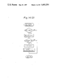
- FIGS. 14 (1), (2), and (3) illustrate a basic control process, a retrieval routine, and a discrimination routine, respectively;
- FIGS. 15, 16, and 17 illustrate second and third embodiments; in which FIGS. 15 (1) and (2) show the second embodiment of the means for detecting long and short size marks; and FIGS. 15 (3) and (4) show the third embodiment of the detecting means for detecting wide and narrow size marks;
- FIG. 16 shows a block diagram of the control means; and
- FIG. 17 shows a flow chart of the basic control;
- FIGS. 18 to 21 illustrate a fourth embodiment using dark size marks and light size marks; in which FIGS. 18 (1) and (2) show the detecting means, FIG. 19 shows the control means; FIG. 20 shows the respective signals; and FIG. 21 shows a block diagram of the basic control;
- FIGS. 22, 23 and 24 (1), 24 (2), and 24 (3) illustrate a fifth embodiment using two size marks an one size mark for indicating different sizes; in which FIGS. 22 (1) and (2) show the detecting means; FIG. 23 shows the control means; and FIGS. 24 (1), 24 (2) and 24 (3) show the control process thereof; and,
- FIGS. 25, 26, and 27 illustrate a sixth embodiment for detecting two size marks and one size mark by an exclusive third detecting element; in which FIGS. 25 (1) and (2) show the detecting means; FIG. 26 shows the control means; and FIG. 27 shows the basic control process.
- the microfilm 1 is an elongated roll film strip having a width of 16 or 35 mm, and includes a plurality of continuous microimages 28 and 29 of two kinds of sizes. These two sizes are the sizes of the microimages corresponding to, for example, A3 and A4. However, the combination of sizes of course may be, for example, B4 and B5, A4 and A5, or any other combination. There also may be a combination of three kinds of sizes.
- the roll film 1 may be a single stage simple reflex type or a two stage "duo" type.
- the roll film 1 has size marks 30 and 31 indicating the sizes of the respective microimages 28 and 29 adjacent thereto, and located at a margin of the microfilm 1.
- the A3 size microimage 28 is provided with the marks 30
- the A4 size microimage 29 is provided with the marks 31, respectively.
- Each mark 30 and 31 has an optical transparency different from that of a peripheral film base F.
- the size marks 30 and 31 are made distinctive from each other so as to be detectable by a detecting means as mentioned hereinafter.
- the respective portions (1) illustrate films including long marks 30L and short marks 31L which have different lengths along the longitudinal direction of the microfilm 1; the respective portions (2) illustrate films including wide marks 30W and narrow marks 31W which have different widths along the transverse direction of the microfilm 1; the respective portion (3) illustrate films including dark marks 30D and light marks 31D which have different optical transparencies; and the respective portions (4) illustrate films including marks 30N and marks 31N which have a different number, but the same size, of respective mark areas.
- the marks 30 and 31 also can be made distinguishable by changing the respective color, various size, shape, position, and the like.
- the size marks 30L and 31L having different lengths, as shown in FIGS. 1, 2, and 3 by the portions (1) can be constituted by applying conventional blip marks B thereto.
- the sizes of the respective microimages 28 and 29 have the 30 and 31 indicating their sizes, it is also possible to detect the sizes of the microimages 28 and 29 by detecting whether or not there is a size mark. Therefore, in order the distinguish two kinds of sizes of the microimages 28 and 29, it is not always necessary to provide a plurality of distinguishing marks.
- the blip mark B is conventionally used as a frame detection mark, a frame group (or case) indication mark, or the like, for accessing a frame page of the respective microimages 28 and 29, or a frame group consisting of a series of frames, or for determining a frame position.
- the channel B i.e., the upper margin in the drawing of the microfilm 1
- the channel A i.e., the lower margin in the drawing of the microfilm 1
- the channel B is not provided with marks, but the channel A is provided with marks which serve both for the size marks 30 and 31 and for the conventional blip marks B as frame detection marks.
- the conventional blip marks used as frame detection marks also can be rearranged to be used as size marks 30 and 31.
- the channel B is provided with the blip marks B 1 as frame group indication marks
- the channel A is provided with marks which serve both for the size marks 30 and 31 and for conventional blip marks B 2 as frame group indication marks.
- the above-mentioned marks which serve both for the size marks 30 and 31 and for conventional blip marks B 1 as frame detection marks have an advantage in that a means for detecting conventional blip marks B can be most easily applied for this purpose.
- long marks may also be used as blip marks B 1 serving as frame group indication marks
- middle and short marks also may be used as the marks which serve both for the blip marks B 1 as frame detection marks and for the size marks 30L and 31L.
- each of the size marks 30 and 31 is aligned with the front edge of each of the microimages 28 and 29. This is advantageous if the marks also serve as marks for frame positioning. On the other hand, as shown in FIG. 4 (2), the marks also may be located at the respective center positions of the microimages 28 and 29 in the longitudinal direction of the microfilm 1.
- the microfilm 1 shown in FIGS. 1, 2, 3, and 4 is a roll film as mentioned above, but a fish film, as shown in FIG. 5, also may be used for this purpose. Consequently, the fish film in which a plurality of microimages 28 and 29 are arranged in multistages, regardless of whether or not it is, for example, a jacket type, includes size marks 30 and 31 in a similar manner as mentioned above.
- FIG. 5 (1) an embodiment is shown in which the front edges of the long size marks 30L and the short size marks 31L are aligned with the front edges of the respective microimages 28 and 29.
- FIG. 5 (2) illustrates an embodiment in which such marks are located at the central positions of the respective microimages 28 and 29 in the longitudinal direction of the microfilm 1.
- FIGS. 6, 7, 8, and 9 illustrate an embodiment of a reader printer, in which FIG. 6 is a block diagram of the basic system thereof, FIG. 7 is a perspective view of the printer, FIG. 8 is a front view thereof, and FIG. 9 is a side elevational cross-sectional view thereof.
- a reader printer according to this invention generally includes a microfilm 1, a sheet supplying means 13, a detecting means 44, and a control means 53. This reader printer is operated either in a reading mode, in which the microimages in the microfilm 1 are set in a predetermined place and enlarged and projected onto a screen 2, or in a printing mode, in which the enlarged images are printed on copying sheets.
- a light source 3 such as a luminance lamp
- a condenser lens 4 is focussed by a condenser lens 4 and irradiated toward the lower surface of the microfilm 1 so that a microimage is enlarged by a projection lens 5.
- the light is reflected by a reader first mirror 6, which exists in a reading position (a lower position in FIG. 9), and a fixed reader second mirror 7, so that the enlarged image is projected on the screen 2 which is located at an upper front position of the printer body.
- a print first mirror 8 and a print third mirror 9 are in the right and front positions, respectively, so that they are retracted from the reader light path.
- the above-mentioned reader first mirror 6 is moved upward from the reading position and retracted from the printer light path.
- the print first mirror 8 and print third mirror 9 are simultaneously moved leftward and rearward, respectively, to a scanning start position, and subsequently, are moved rightward and forward, respectively, toward a scanning end position to conduct scanning.
- the light is transversely reflected by the print first mirror 8, directed rearward by a fixed print second mirror 10, and directed downward by the print third mirror 9.
- the microimage is slit-exposed through a fixed fourth mirror 11 on a drum-like photosensitive media 12, so that an enlarged latent image is formed on the photosensitive media 12 which is uniformly static-electrified.
- a sheet supplying means generally indicated by a reference numeral 13 is capable of selectively supplying one of various sizes of copying sheets, in accordance with a signal from the control means 53, to a transfer station as mentioned hereinafter.
- pickup rollers 14 and 15 are arranged in sheet cassettes 16 and 17, respectively, in such a manner that they are in firm contact with the uppermost of the sheets of various sizes, such as A3 and A4, accommodated in the sheet cassettes 16 and 17, respectively.
- the pickup rollers 14 and 15 are selectively rotated by driving means switched in accordance with signals selectively output from a control means 53.
- either the pickup roller 14 or the pickup roller 15 is rotated so as to supply either A4 or A3 copying sheets from the corresponding cassette 16 or 17.
- the copying sheets are subsequently fed by rollers 18 or 19, arranged in certain positions, and rollers 20 to timing rollers 21, which are arranged in the vicinity of the transfer means 23.
- the front edges of the copying sheets are detected by a sensor 22 so as to intercept the driving force from transmitting to the rollers 20 and so on.
- the sizes of the copying sheets accommodated in the cassettes 16 and 17 correspond to the respective sizes of the microimages on the microfilm 1, which may be any combination of sheet sizes, such as A3 and A4, as well as B4 and B5, A4 and B5, and the like. It is also possible to increase the number of cassettes so that the variety of sheet sizes can be increased.
- the latent image formed on the photosensitive media 12 as mentioned above is then developed by adhering toner thereto and transferred to the copying sheet supplied by the timing roller 21 driven synchronously with the forward edge of the developed image on the photosensitive media 12.
- the transferred sheet is then fed by a feeding means 24 to a heating and fixing station 25, in which the transferred image is fixed on the copying sheet.
- the copied sheet is discharged by rollers 26 to a copy tray 27 located in a front part of the printer body.
- reference numeral 45 indicates a roll-film carrier, and 46 a control board.
- FIG. 10 is a perspective view illustrating a roll film carrier 45, in which reference numeral 1 indicates a roll film type microfilm; 3, a light source; 4, a condenser lens; 5, a projecting lens; 32, a roll film cartridge; and 33, a feed roller for feeding the microfilm 1 accommodated in the cartridge 32.
- the feed roller 33 is rotated by a drive motor A 34 and comes into contact with the microfilm 1 in the cartridge 32 when a solenoid 35 is turned ON, but moves away from the microfilm 1, when the solenoid 35 is turned OFF.
- the microfilm 1 supplied from the cartridge 32 by the feed roller 33 is then guided along an idle roller 36 and transported in the direction X to the plate portion 37.
- a drive motor 41 serves to rewind the microfilm 1 in the direction Y opposite to X, to accommodate the film in the cartridge 32.
- An encoder 42 is connected to the idle roller 36 to generate a pulse signal in proportion to the distance moved by the microfilm 1.
- the plate portion 37 is provided at the center thereof with an aperture 43, which is located so as to be aligned with the microimages 28 and 29 of the microfilm 1 and between the condenser lens 4 the projecting lens 5.
- a detecting means 44 serves to detect the size marks 30 and 31 of the respective microimages 28 and 29 as well as the presence of such size marks.
- This detecting means 44 is arranged at or over the aperture 43 of the plate portion 37 so as to receive optical signals from the light source 3, which signals have been transmitted through the size marks 30 or 31, or film base F therearound, and to output electrical signals when detecting the size marks 30 and 31.
- the detecting means 44 may be made from any one of photoelectric elements, such as CdS, or any one of photovoltaic elements, such as SPD, or may be one of any other elements generally used for such a purpose. The number, position, or arrangement of such detecting elements should be determined in accordance with the actual embodiments of the detected objects, i.e., the size marks 30 and 31.
- the timing for detecting the size marks 30 and 31 may be the time when the microimages 28, 29 are projected onto the screen 2 in the reading mode, or the time for retrieving or searching by means of blip marks B, or the time when the printing key is ON, or any other time.
- FIG. 11 illustrates a first embodiment of the detecting means 44 including two detecting elements, one for detecting long size marks 30L and the other for detecting short marks 31L. That is, the detecting means 44 in this embodiment includes two optical fibers 47 and 48 having light receiving portions 49 and 50, respectively, which are arranged in series in the longitudinal direction of the microfilm 1 so as to face the long and short size marks 30L and 31L and the film base F therearound, and are connected to first and second optical detecting elements 51 and 52 respectively.
- the optical signals from the long and short size marks 30L and 31L and the film base F therearound are received by the respective light receiving portions 49 and 50 and transmitted through the optical fibers 47 and 48 to the first and second optical detecting elements 51 and 52, whereby the optical signals are changed to electrical signals.
- the distance between both light receiving portions 49 and 50 is shorter than the shorter size mark 31L, and is determined so that noise is not generated.
- the detecting means 44 and the long and short size marks 30L and 31L also serve for the blip marks B, exclusive marks and an exclusive detecting means may be, of course, employed. This also applies to the other embodiments as mentioned hereinafter.
- the optical fibers 47 and 48, the first and second detecting elements 51 and 52, and the like, are covered by a cover member K and mounted on the plate portion 37 around the aperture 43.
- a control means 53 selectively outputs a sheet supply signal to the sheet supplying means 13 in accordance with the detected signals obtained by the above-mentioned detecting means 44.
- FIG. 12 is a block diagram showing a first embodiment of the control means 53.
- FIG. 13 is a timing chart illustrating the various signals in this control means 53 and shows the signals of the size marks 30L and 31L passing through the first and second detecting elements 51 and 52, where the speed of the microfilm 1 is constant.
- First and second mark detectors 54 and 55 are buffers for the first and second detecting elements 51 and 52, respectively, of the detecting means 44. These detectors 54 and 55 receive the output signals from the corresponding detecting elements 51 and 52, respectively, amplify and reform the wave of the signals, and generate mark-detected signals ⁇ A and ⁇ B , such as voltage level "1" or the like, when the first and second detecting elements 51 and 52 detect the size marks 30L and 31L.
- the mark-detected signals ⁇ A , and the signals ⁇ B reversed therefrom through a NOT gate 56, are sent to an AND gate 57, and an output signal ⁇ C therefrom is sent to a positioning detector 58, an output of which is supplied to the microcomputor 59.
- the mark-detected signals ⁇ A and ⁇ B are sent to an OR gate 60, an output of which is given as a frame mark signal ⁇ D to an AND gate 61, a frame counter 62, and the microcomputor 59.
- the AND gate 61 is opened or closed in accordance with the frame mark signal ⁇ D and receives the pulse signal ⁇ E from the encoder 42. Therefore, the number of pulses ⁇ F which have passed while the gate is open, on the basis of the frame signal ⁇ D , is counted in a counter 63, so that the count "n” in the counter 63 corresponds to the length of the size mark 30L or 31L. Then, the count "n” is read out by the microcomputor 59 and compared with a predetermined value "n 0 " to discriminate the size of the microimage 28 or 29, so that the status of the size flag m corresponding to the frame number m is determined.
- the microcomputor 59 selectively outputs a signal 64 for A3 sheets or a signal 65 for A4 sheets to the sheet supplying means 13 in accordance with the status of the size flag m. Therefore, in the sheet supplying means 13, a drive means is changed so as to drive either the pick-up roller 14 or the pickup roller 15 to supply the corresponding A3 or A4 size copying sheets to the transferring means 23 from the corresponding sheet cassettes 16 or 17.
- the positioning of the microfilm 1 is carried out as follows.
- the microcomputor 59 outputs control signals to the motor 39 and motor 41 in accordance with input of the above-mentioned frame mark counter 62, frame mark signal ⁇ D , and input of the positioning detector 58.
- microfilm 1 is transported in the direction X and searched. If the count number of the frame mark counter 62 reaches the frame m in question, the microfilm 1 once passes through the aperture 43 until the frame mark signal ⁇ D is turned OFF while the frame mark signal ⁇ D is observed. Then, the microfilm 1 is reversed in the rewinding direction Y and controlled by the signal from the positioning detector 58, and the microimage 28 or 29 in question is positioned at a projecting position facing the aperture 43 and is stopped.
- the size discrimination as mentioned above is carried out while the microfilm 1 is positioned as such.
- the sheet supplying means should be, of course, constructed to supply three or more sizes sheets, correspondingly.
- key input for instructing the count number m is indicated at 66.
- FIG. 14 (1) illustrates a basic control process.
- a main switch is turned ON, and therefore the light source 3 is also turned ON, the system is started.
- the microfilm 1 supplied and transported from the cartridge 32 is irradiated with the light from the light source 3 at a position opposite to the aperture 43 of the plate portion 37. Then the initializing, reading, and retrieval processes are conducted in succession.
- FIG. 14 (2) illustrates a retrieval routine. After a key input, registering processes, such as setting frame for searching, are processed, and a retrieval process is started when a search key is turned ON.
- the frame m in question is retrieved by the frame marks, i.e., blip marks B, of the microimages 28 and 29 and stored in a memory for positioning.
- the size discrimination process is carried out by means of size marks 30L and 31L.
- FIG. 14 (3) illustrates a discrimination routine.
- the optical signal from the size mark 30 or 31 of the microimage 28 or 29 is detected by the detecting means 44.
- the count "n" in the discriminating counter 63 is read out by the microcomputor 59.
- the counter 63 is reset for a counting operation for the next frame.
- size discrimination of the microimage 28 or 29 is conducted by comparing the count value with the above-mentioned predetermined value "n 0 ".
- the value “n 0 " is predetermined as a value between “n” for A3 size and “n” for A4 size. If the count “n” for A3 is 5 or 6 and the count “n” for A4 is 3 or 4, the value “n 0 " can be set as 5, since the count "n” is substantially constant and corresponds to the distance of sheet transportion, regardless of the speed thereof.
- the status of the size flag m corresponding to the frame number m of the microimage 28 is set as A3, i.e., "1". If the result is NO, the status of the size flag m corresponding to the frame number m of the microimage 29 is set as A4, i.e., "0". The process then returns to the start.
- size discrimination is thus attained by conducting such discrimination only for the microimage 28 or 29 in question. But it would be more effective if the size flag m and the status thereof are set, in a place of the flag area m of the memory corresponding to the frame number m in question, and thereafter printing is conducted with reference to the status thereof for the frame which has been once discriminated. In such an embodiment, since the size discrimination can be done while passing through the frames, it would be more advantageous if, during the search operation, all of the frames passing therethrough are subjected to the size discrimination, and thereafter the printing process is effected with reference to the status of the memorized respective size flag m.
- the microcomputor 59 of the control means 53 selectively outputs a sheet supply signal for supplying either A3 or A4 copying sheets.
- the sheet supply means 13 selectively supplies either A3 or A4 size copying sheets to the transferring means 23 for printing. After the printing process, the system is returned to the reading mode.
- FIGS. 15, 16, and 17 illustrate second and third embodiments of the present invention, in which FIGS. 15 (1) and (2) show the second embodiment of the means for detecting long and short size marks 30L and 31L, and FIGS. 15 (3) and (4) show the third embodiment of the detecting means for detecting wide and narrow size marks 30W and 31W.
- FIG. 16 shows a block diagram of the control means 53
- FIG. 17 shows a flow chart of the basic control.
- first and second detecting elements 51 and 52 serve only to detect blip marks B
- a third detecting element 67 serves to detect size marks 30 and 31.
- the optical signal from the size marks 30L, W and 31L, W and the film base F therearound is received by a light receiving portion 68 and transmitted through an optical fiber 69 to the third optical detecting element 67, by which the optical signal is changed to an electrical signal.
- the detected signal is transmitted to a third mark detector 70.
- the microcomputor 59 observes whether the output signal from the third detector 70 is ON or OFF while a frame counter is counting the frame number m and effects the size discrimination.
- the light receiving portion 68 of the third detecting element 67 is arranged in series in the longitudinal direction with respect to the light receiving portions 49 and 50 of the first and second detecting elements 51 and 52 so as to detect the size marks 30L and 31L.
- the light receiving portion 68 is arranged offset from the longitudinal line, on which the light receiving portions 49 and 50 are arranged, in the direction of width by a distance larger than the width of the narrower size mark 31W so as to detect the presence of size marks 30W and 31W.
- the third detecting element 67 is not used for positioning, the light receiving portion 68 may be arranged at a position other than the illustrated position, provided that the location is limited by the shapes of the size marks 30W and 31W. Retrieval and positioning can be conducted in the same manner as in the above-mentioned first embodiment.
- the encoder 42 for size discrimination is not necessary.
- the size discrimination can be done either when the microfilm 1 is transported or stopped. In FIG. 17, after the searching is in process, and after the printing key is turned ON, the size discrimination is conducted by observing the third detecting element 67.
- FIGS. 18 to 21 illustrate a fourth embodiment using dark size marks 30D and light size marks 31D, in which FIG. 18 shows the detecting means 44, FIG. 19 shows the control means 53, FIG. 20 shows the respective signals, and FIG. 21 shows a block diagram of the basic control.
- the signals of the first and second detecting elements 51 and 52 for detecting the size marks 30D and 31D, respectively, are amplified by amplifiers 71 and 72 and supplied to comparators 73, 74, and 75 as signals ⁇ G and ⁇ H , respectively.
- the comparative voltage has two standard points Th1 and Th2.
- the signal ⁇ G or ⁇ H from the detecting element 51 or 52 for the positioned size mark 30D or 31D is divided by the two standard points Th1 and Th2.
- Th1 serves to detect the blip marks B.
- the signal ⁇ I or ⁇ J from the comparator 73 or 74 is reformed at an AND gate 76 to be a signal ⁇ L , which is supplied to a frame mark counter 62 and positioning detector 58 and input to the microcomputor 59 in which retrieval positioning is conducted.
- Th2 serves to initiate size discrimination.
- the signal ⁇ K for density is input from the comparator 75 to the microcomputor 59, in which size discrimination is carried out on the basis of a signal ON or OFF.
- Reference numerals 77 and 78 indicate semi-solid resistances for setting the level of density.
- retrieval and positioning can be conducted in a conventional manner and it is easy to use the marks both as size marks 30D and 31D and as blip marks B.
- FIGS. 22, 23 and 24 illustrate a fifth embodiment using two size marks 30N and one size mark 31N, in which FIG. 22 shows the detecting means 44, FIG. 23 shows the control means 53, and FIGS. 24 (1), (2) and (3) show the control process thereof.
- the construction of the detecting means 44 is substantially the same as that of the first embodiment.
- the encoder 42 for size discrimination is not necessary.
- the size discrimination can be conducted while the frames pass through, in the same manner as mentioned above in the first embodiment, it would be more effective to discriminate the size of the frames having passed through, and thereafter, to conduct the printing with reference to the status of the size flag m corresponding to the respective memorized frames.
- the microfilm 1 is stopped and positioned. Since each size mark 30N consists of two marks, the manner of stopping the microfilm 1 must be taken into account. That is to say, the manner necessary when the microfilm 1 is transported in the direction X is different from that when it is transported in the rewinding direction Y. In the positioning detector 58 served for this purpose, the microfilm 1 might be stopped at a position corresponding to the head of the first mark of each size marks 30N and 31N.
- FIGS. 25, 26, and 27 illustrate a sixth embodiment for detecting two size marks 30N and one size mark 31N by an exclusive third detecting element 67, in which FIG. 25 shows the detecting means, FIG. 26 shows the control means 53, and FIG. 27 shows the basic control process.
Abstract
Description
Claims (8)
Applications Claiming Priority (4)
| Application Number | Priority Date | Filing Date | Title |
|---|---|---|---|
| JP17209985A JPS6232434A (en) | 1985-08-05 | 1985-08-05 | Microfilm |
| JP60-172099 | 1985-08-05 | ||
| JP19290185A JPS6252542A (en) | 1985-08-31 | 1985-08-31 | Printer for microfilm |
| JP60-192901 | 1985-08-31 |
Publications (1)
| Publication Number | Publication Date |
|---|---|
| US4693591A true US4693591A (en) | 1987-09-15 |
Family
ID=26494572
Family Applications (1)
| Application Number | Title | Priority Date | Filing Date |
|---|---|---|---|
| US06/890,479 Expired - Fee Related US4693591A (en) | 1985-08-05 | 1986-07-30 | Microfilm and microfilm printer |
Country Status (1)
| Country | Link |
|---|---|
| US (1) | US4693591A (en) |
Cited By (31)
| Publication number | Priority date | Publication date | Assignee | Title |
|---|---|---|---|---|
| US4738523A (en) * | 1985-04-29 | 1988-04-19 | Minolta Camera Kabushiki Kaisha | Retrieval control apparatus for microfilm reader |
| US4777515A (en) * | 1986-10-01 | 1988-10-11 | Canon Kabushiki Kaisha | Image recording apparatus |
| US4785334A (en) * | 1986-12-17 | 1988-11-15 | Minolta Camera Kabushiki Kaisha | Image forming apparatus |
| US4803505A (en) * | 1986-09-03 | 1989-02-07 | Minolta Camera Kabushiki Kaisha | Microfilm camera |
| US4843432A (en) * | 1986-01-13 | 1989-06-27 | Canon Kabushiki Kaisha | Image recording apparatus |
| US4903073A (en) * | 1987-03-31 | 1990-02-20 | Minolta Camera Kabushiki Kaisha | Image projecting apparatus with margin detect means |
| US4908654A (en) * | 1988-11-14 | 1990-03-13 | Eastman Kodak Company | Method and apparatus for automatic printing from microfilm of short image areas |
| US4931863A (en) * | 1987-07-31 | 1990-06-05 | Fuji Photo Film Co., Ltd. | Electronic photographic printer/enlarger |
| US4931832A (en) * | 1988-04-28 | 1990-06-05 | Fuji Photo Film Co., Ltd. | Method of specifying frame number |
| US4972068A (en) * | 1986-07-26 | 1990-11-20 | Canon Kabushiki Kaisha | Retrieval apparatus readily adaptable for use with various types of recording media |
| US5020900A (en) * | 1988-11-07 | 1991-06-04 | Canon Kabushiki Kaisha | Film feeding apparatus |
| US5023656A (en) * | 1989-04-20 | 1991-06-11 | Fuji Photo Film Co., Ltd. | Photographic printing method |
| US5072408A (en) * | 1989-04-07 | 1991-12-10 | Minolta Camera Kabushiki Kaisha | Microfilm handling system |
| US5151726A (en) * | 1987-05-09 | 1992-09-29 | Canon Kabushiki Kaisha | Camera or printer capable of automatically changing print size |
| US5202724A (en) * | 1990-11-28 | 1993-04-13 | Minolta Camera Kabushiki Kaisha | Microfilm camera |
| US5278609A (en) * | 1991-06-27 | 1994-01-11 | Fuji Photo Film Co., Ltd. | Microfilm reader and microfilm used therein |
| US5406350A (en) * | 1993-12-27 | 1995-04-11 | Eastman Kodak Company | Image recording apparatus |
| US5872619A (en) * | 1996-09-19 | 1999-02-16 | Eastman Kodak Company | Method and apparatus for printing zoomed photographs from negatives with pseudo zoomed widths |
| US5897232A (en) * | 1996-09-19 | 1999-04-27 | Eastman Kodak Company | Camera with widthwise pseudo zoom masks and method of exposing a pseudo zoom image |
| US5934167A (en) * | 1994-03-17 | 1999-08-10 | Noritsu Koki Co., Ltd. | Photographic material feeder apparatus |
| EP1033610A2 (en) * | 1988-08-31 | 2000-09-06 | Sony Corporation | Photographic camera systems and film cassettes |
| EP1054291A1 (en) * | 1992-03-17 | 2000-11-22 | Sony Corporation | Photograhpic film printer |
| US6347193B1 (en) | 1992-03-17 | 2002-02-12 | Sony Corporation | Photographic and video image system |
| US6349176B1 (en) | 1992-03-17 | 2002-02-19 | Sony Corporation | Photographic camera system |
| US6366337B1 (en) | 1992-03-17 | 2002-04-02 | Sony Corporation | Photographic and video image system |
| US6438325B2 (en) | 1992-03-17 | 2002-08-20 | Sony Corporation | Photographic camera system |
| US6470152B2 (en) | 1992-03-17 | 2002-10-22 | Sony Corporation | Photographic and video image system |
| US6583851B2 (en) | 1992-03-17 | 2003-06-24 | Sony Corporation | Photographic and video image system |
| US6600880B2 (en) | 1992-03-17 | 2003-07-29 | Sony Corporation | Photographic camera system |
| US20060294013A1 (en) * | 1999-12-28 | 2006-12-28 | Sony Corporation | Image commercial transactions system and method, image transfer system and method, image distribution system and method, display device and method |
| US7225158B2 (en) | 1999-12-28 | 2007-05-29 | Sony Corporation | Image commercial transactions system and method |
Citations (10)
| Publication number | Priority date | Publication date | Assignee | Title |
|---|---|---|---|---|
| US3136463A (en) * | 1960-03-30 | 1964-06-09 | Photo Copie G M B H | Attachment for microfilm flow type cameras |
| US3744890A (en) * | 1970-10-09 | 1973-07-10 | Ricoh Kk | System for searching for desired information |
| JPS5053050A (en) * | 1973-09-04 | 1975-05-10 | ||
| US3885855A (en) * | 1971-08-16 | 1975-05-27 | Battelle Memorial Institute | Filtering antisolar and heat insulating glass |
| US3981582A (en) * | 1975-09-30 | 1976-09-21 | Bell & Howell Company | Microfilm copyboard with document index |
| US4116560A (en) * | 1977-06-06 | 1978-09-26 | James J. Dragani | Apparatus and method for document microfilming system |
| US4277165A (en) * | 1977-03-16 | 1981-07-07 | Minolta Camera Kabushiki Kaisha | Photocopying machine equipped with variable magnification arrangement |
| US4408876A (en) * | 1981-11-27 | 1983-10-11 | Motion Technology Corporation | Method and apparatus for microfilming documents of varied length |
| JPS5930550A (en) * | 1982-08-13 | 1984-02-18 | Fuji Xerox Co Ltd | Microfilm copying machine |
| US4597663A (en) * | 1984-04-05 | 1986-07-01 | Sharp Kabushiki Kaisha | Electrophotographic copying machine of automatic magnification/reduction-controllable type |
-
1986
- 1986-07-30 US US06/890,479 patent/US4693591A/en not_active Expired - Fee Related
Patent Citations (10)
| Publication number | Priority date | Publication date | Assignee | Title |
|---|---|---|---|---|
| US3136463A (en) * | 1960-03-30 | 1964-06-09 | Photo Copie G M B H | Attachment for microfilm flow type cameras |
| US3744890A (en) * | 1970-10-09 | 1973-07-10 | Ricoh Kk | System for searching for desired information |
| US3885855A (en) * | 1971-08-16 | 1975-05-27 | Battelle Memorial Institute | Filtering antisolar and heat insulating glass |
| JPS5053050A (en) * | 1973-09-04 | 1975-05-10 | ||
| US3981582A (en) * | 1975-09-30 | 1976-09-21 | Bell & Howell Company | Microfilm copyboard with document index |
| US4277165A (en) * | 1977-03-16 | 1981-07-07 | Minolta Camera Kabushiki Kaisha | Photocopying machine equipped with variable magnification arrangement |
| US4116560A (en) * | 1977-06-06 | 1978-09-26 | James J. Dragani | Apparatus and method for document microfilming system |
| US4408876A (en) * | 1981-11-27 | 1983-10-11 | Motion Technology Corporation | Method and apparatus for microfilming documents of varied length |
| JPS5930550A (en) * | 1982-08-13 | 1984-02-18 | Fuji Xerox Co Ltd | Microfilm copying machine |
| US4597663A (en) * | 1984-04-05 | 1986-07-01 | Sharp Kabushiki Kaisha | Electrophotographic copying machine of automatic magnification/reduction-controllable type |
Cited By (51)
| Publication number | Priority date | Publication date | Assignee | Title |
|---|---|---|---|---|
| US4738523A (en) * | 1985-04-29 | 1988-04-19 | Minolta Camera Kabushiki Kaisha | Retrieval control apparatus for microfilm reader |
| US4843432A (en) * | 1986-01-13 | 1989-06-27 | Canon Kabushiki Kaisha | Image recording apparatus |
| US4972068A (en) * | 1986-07-26 | 1990-11-20 | Canon Kabushiki Kaisha | Retrieval apparatus readily adaptable for use with various types of recording media |
| US4803505A (en) * | 1986-09-03 | 1989-02-07 | Minolta Camera Kabushiki Kaisha | Microfilm camera |
| US4777515A (en) * | 1986-10-01 | 1988-10-11 | Canon Kabushiki Kaisha | Image recording apparatus |
| US4785334A (en) * | 1986-12-17 | 1988-11-15 | Minolta Camera Kabushiki Kaisha | Image forming apparatus |
| US4903073A (en) * | 1987-03-31 | 1990-02-20 | Minolta Camera Kabushiki Kaisha | Image projecting apparatus with margin detect means |
| US5151726A (en) * | 1987-05-09 | 1992-09-29 | Canon Kabushiki Kaisha | Camera or printer capable of automatically changing print size |
| US4931863A (en) * | 1987-07-31 | 1990-06-05 | Fuji Photo Film Co., Ltd. | Electronic photographic printer/enlarger |
| US4931832A (en) * | 1988-04-28 | 1990-06-05 | Fuji Photo Film Co., Ltd. | Method of specifying frame number |
| EP1033610A3 (en) * | 1988-08-31 | 2001-05-02 | Sony Corporation | Photographic camera systems and film cassettes |
| EP1033611A3 (en) * | 1988-08-31 | 2001-05-02 | Sony Corporation | Photographic camera systems and film cassettes |
| EP1033612A2 (en) * | 1988-08-31 | 2000-09-06 | Sony Corporation | Photographic camera systems and film cassettes |
| EP1033607A2 (en) * | 1988-08-31 | 2000-09-06 | Sony Corporation | Photographic camera systems and film cassettes |
| EP1033607A3 (en) * | 1988-08-31 | 2001-05-02 | Sony Corporation | Photographic camera systems and film cassettes |
| EP1033608A3 (en) * | 1988-08-31 | 2001-05-02 | Sony Corporation | Photographic camera systems and film cassettes |
| EP1033612A3 (en) * | 1988-08-31 | 2001-05-02 | Sony Corporation | Photographic camera systems and film cassettes |
| EP1033609A3 (en) * | 1988-08-31 | 2001-05-02 | Sony Corporation | Photographic camera systems and film cassettes |
| EP1033609A2 (en) * | 1988-08-31 | 2000-09-06 | Sony Corporation | Photographic camera systems and film cassettes |
| EP1033608A2 (en) * | 1988-08-31 | 2000-09-06 | Sony Corporation | Photographic camera systems and film cassettes |
| EP1033610A2 (en) * | 1988-08-31 | 2000-09-06 | Sony Corporation | Photographic camera systems and film cassettes |
| EP1033611A2 (en) * | 1988-08-31 | 2000-09-06 | Sony Corporation | Photographic camera systems and film cassettes |
| US5020900A (en) * | 1988-11-07 | 1991-06-04 | Canon Kabushiki Kaisha | Film feeding apparatus |
| US4908654A (en) * | 1988-11-14 | 1990-03-13 | Eastman Kodak Company | Method and apparatus for automatic printing from microfilm of short image areas |
| US5072408A (en) * | 1989-04-07 | 1991-12-10 | Minolta Camera Kabushiki Kaisha | Microfilm handling system |
| US5023656A (en) * | 1989-04-20 | 1991-06-11 | Fuji Photo Film Co., Ltd. | Photographic printing method |
| US5202724A (en) * | 1990-11-28 | 1993-04-13 | Minolta Camera Kabushiki Kaisha | Microfilm camera |
| US5278609A (en) * | 1991-06-27 | 1994-01-11 | Fuji Photo Film Co., Ltd. | Microfilm reader and microfilm used therein |
| US6438325B2 (en) | 1992-03-17 | 2002-08-20 | Sony Corporation | Photographic camera system |
| US6470152B2 (en) | 1992-03-17 | 2002-10-22 | Sony Corporation | Photographic and video image system |
| US20040239805A1 (en) * | 1992-03-17 | 2004-12-02 | Sony Corporation | Photographic and video image system |
| US6778774B2 (en) | 1992-03-17 | 2004-08-17 | Sony Corporation | Photographic and video image system |
| EP1054291A1 (en) * | 1992-03-17 | 2000-11-22 | Sony Corporation | Photograhpic film printer |
| US6347193B1 (en) | 1992-03-17 | 2002-02-12 | Sony Corporation | Photographic and video image system |
| US6349176B1 (en) | 1992-03-17 | 2002-02-19 | Sony Corporation | Photographic camera system |
| US6366337B1 (en) | 1992-03-17 | 2002-04-02 | Sony Corporation | Photographic and video image system |
| US6600880B2 (en) | 1992-03-17 | 2003-07-29 | Sony Corporation | Photographic camera system |
| US6583851B2 (en) | 1992-03-17 | 2003-06-24 | Sony Corporation | Photographic and video image system |
| US6463217B1 (en) | 1992-03-17 | 2002-10-08 | Sony Corporation | Photographic and video image system |
| US6574440B2 (en) | 1992-03-17 | 2003-06-03 | Sony Corporation | Photographic camera system |
| US6571067B2 (en) | 1992-03-17 | 2003-05-27 | Sony Corporation | Photographic camera system |
| US6434339B1 (en) | 1993-03-04 | 2002-08-13 | Sony Corporation | Photographic and video image system |
| US5406350A (en) * | 1993-12-27 | 1995-04-11 | Eastman Kodak Company | Image recording apparatus |
| US5934167A (en) * | 1994-03-17 | 1999-08-10 | Noritsu Koki Co., Ltd. | Photographic material feeder apparatus |
| US5897232A (en) * | 1996-09-19 | 1999-04-27 | Eastman Kodak Company | Camera with widthwise pseudo zoom masks and method of exposing a pseudo zoom image |
| US5872619A (en) * | 1996-09-19 | 1999-02-16 | Eastman Kodak Company | Method and apparatus for printing zoomed photographs from negatives with pseudo zoomed widths |
| US20060294013A1 (en) * | 1999-12-28 | 2006-12-28 | Sony Corporation | Image commercial transactions system and method, image transfer system and method, image distribution system and method, display device and method |
| US20070050821A1 (en) * | 1999-12-28 | 2007-03-01 | Sony Corporation | Image commercial transactions system and method, image transfer system and method, image distribution system and method,display device and method |
| US7225158B2 (en) | 1999-12-28 | 2007-05-29 | Sony Corporation | Image commercial transactions system and method |
| US8271388B2 (en) | 1999-12-28 | 2012-09-18 | Sony Corporation | Image commercial transactions system and method, image transfer system and method, image distribution system and method, display device and method |
| US8306917B2 (en) | 1999-12-28 | 2012-11-06 | Sony Corporation | Image commercial transactions system and method |
Similar Documents
| Publication | Publication Date | Title |
|---|---|---|
| US4693591A (en) | Microfilm and microfilm printer | |
| US4659213A (en) | Method and apparatus for detecting and processing image information | |
| EP0331049B1 (en) | Apparatus for reading bar code of photographic film | |
| EP0721149B1 (en) | Method for communicating scene orientation of camera film to photo finishing equipment | |
| US4777515A (en) | Image recording apparatus | |
| US4972068A (en) | Retrieval apparatus readily adaptable for use with various types of recording media | |
| US4745489A (en) | Image recording apparatus for recording only the image area of a film | |
| EP0590383B1 (en) | A full frame/panoramic photographic printing apparatus and method | |
| US5432586A (en) | Photographic printing apparatus and automatic cutter | |
| US4453823A (en) | Method of stopping a film | |
| EP0423809B1 (en) | Microfilm reader/printer | |
| US5831741A (en) | Method and apparatus for detecting holes in copy media | |
| JP2531633B2 (en) | Information retrieval device | |
| US5280321A (en) | Dual roll rotary microfilmer for 25x reduction or less | |
| JP2789659B2 (en) | Image information retrieval and copying device | |
| US4843432A (en) | Image recording apparatus | |
| JP2710078B2 (en) | Microfilm search device | |
| US4459018A (en) | Device for singling out non-reproducible copies fed in a photographic printer | |
| JP2885985B2 (en) | Micro film reader | |
| JP2577645B2 (en) | Printing method of micro film printer | |
| JPH04320232A (en) | Microfilm retrieving device | |
| JPS6252542A (en) | Printer for microfilm | |
| JPH0239133A (en) | Information retrieving device | |
| JP2599631B2 (en) | Microfilm reader address display | |
| JPS6232434A (en) | Microfilm |
Legal Events
| Date | Code | Title | Description |
|---|---|---|---|
| AS | Assignment |
Owner name: MINOLTA CAMERA KABUSHIKI KAISHA, C/O OSAKA KOKUSAI Free format text: ASSIGNMENT OF ASSIGNORS INTEREST.;ASSIGNORS:SAIJO, TAKAO;FUJITA, MASAFUMI;REEL/FRAME:004585/0520 Effective date: 19860723 Owner name: MINOLTA CAMERA KABUSHIKI KAISHA, C/O OSAKA KOKUSAI Free format text: ASSIGNMENT OF ASSIGNORS INTEREST;ASSIGNORS:SAIJO, TAKAO;FUJITA, MASAFUMI;REEL/FRAME:004585/0520 Effective date: 19860723 |
|
| FEPP | Fee payment procedure |
Free format text: PAYOR NUMBER ASSIGNED (ORIGINAL EVENT CODE: ASPN); ENTITY STATUS OF PATENT OWNER: LARGE ENTITY |
|
| FPAY | Fee payment |
Year of fee payment: 4 |
|
| FPAY | Fee payment |
Year of fee payment: 8 |
|
| REMI | Maintenance fee reminder mailed | ||
| LAPS | Lapse for failure to pay maintenance fees | ||
| FP | Lapsed due to failure to pay maintenance fee |
Effective date: 19990915 |
|
| STCH | Information on status: patent discontinuation |
Free format text: PATENT EXPIRED DUE TO NONPAYMENT OF MAINTENANCE FEES UNDER 37 CFR 1.362 |