EP0743799B1 - Verfahren und Gerät zur Konturkorrektur von Farbbildsignalen - Google Patents
Verfahren und Gerät zur Konturkorrektur von Farbbildsignalen Download PDFInfo
- Publication number
- EP0743799B1 EP0743799B1 EP96106959A EP96106959A EP0743799B1 EP 0743799 B1 EP0743799 B1 EP 0743799B1 EP 96106959 A EP96106959 A EP 96106959A EP 96106959 A EP96106959 A EP 96106959A EP 0743799 B1 EP0743799 B1 EP 0743799B1
- Authority
- EP
- European Patent Office
- Prior art keywords
- image signal
- color image
- delay means
- line
- delayed
- Prior art date
- Legal status (The legal status is an assumption and is not a legal conclusion. Google has not performed a legal analysis and makes no representation as to the accuracy of the status listed.)
- Expired - Lifetime
Links
- 238000000034 method Methods 0.000 title claims description 27
- 230000003111 delayed effect Effects 0.000 claims description 66
- 230000000007 visual effect Effects 0.000 description 8
- 230000002708 enhancing effect Effects 0.000 description 5
- 238000010586 diagram Methods 0.000 description 4
- 238000000926 separation method Methods 0.000 description 4
- 238000013459 approach Methods 0.000 description 1
- 230000003247 decreasing effect Effects 0.000 description 1
- 230000001419 dependent effect Effects 0.000 description 1
- 238000012986 modification Methods 0.000 description 1
- 230000004048 modification Effects 0.000 description 1
- 230000001629 suppression Effects 0.000 description 1
Images


Classifications
-
- H—ELECTRICITY
- H04—ELECTRIC COMMUNICATION TECHNIQUE
- H04N—PICTORIAL COMMUNICATION, e.g. TELEVISION
- H04N9/00—Details of colour television systems
- H04N9/64—Circuits for processing colour signals
- H04N9/646—Circuits for processing colour signals for image enhancement, e.g. vertical detail restoration, cross-colour elimination, contour correction, chrominance trapping filters
Definitions
- the present invention relates to a method for correcting a contour of a color image signal, and more particularly to a method for correcting a contour of a color television signal in a two-dimensional manner, while a generation of a cross color is suppressed.
- the present invention also relates to an apparatus for carrying out such a contour correction method.
- comb filter method and three-dimensional YC separation method could not be performed on a transmitter side, but could be carried out only on a receiver side.
- a luminance signal Y and a color signal C are separated from each other by utilizing a fact that a color subcarrier frequency component has a phase difference of 180°C between successive lines. Therefore, this contour correction method is effective only for an image signal having purely a horizontal component, but is not effective at all for an image signal of an inclined cross color region, because at the receiver end, the image signal of the inclined cross color region could not be differentiated from the color subcarrier signal.
- the luminance signal and the color signal can be separated from each other in an ideal fashion for a still picture, but for a moving picture, the above mentioned problem in the comb filter method occurs.
- US-4,677,461 describes a contour signal detecting filter for reducing chrominance signal components leaking into horizontal or vertical contour signals.
- the chrominance signal components leaking into the horizontal contour signals are eliminated by using the vertical contour signals, whereby the horizontal components are not outputted as a contour signal.
- the vertical frequency approaches a certain frequency, namely 131.5 c/ph, chrominance signal components leaking into the vertical contour signals are eliminated by using the horizontal contour signals whereby the vertical components are not outputted as a contour signal.
- a contour correction has to be carried out.
- This contour correction could not be dispensed with in view a visual enhancement.
- a frequency range within which the visual enhancement can be actually attained by the contour correction is dependent upon individual persons, but in general, a frequency range of 3-4 MHz is used for a currently available color television system such as NTSC system and PAL system.
- This frequency range corresponds to a frequency range of the color subcarrier.
- this frequency range has to be suppressed as far as possible. That is to say, in a view point of the removal of the cross color, the above mentioned frequency range has to be suppressed, but in a view point of the contour enhancement, this frequency range has to be enhanced as far as possible.
- the present invention has for its object to provide a novel and useful method for correcting a contour of a color television signal, in which the above mentioned conflicting problems can be effectively solved, the cross color can be effectively suppressed even in a range which could not be corrected at a receiver side, and the contour enhancement can be performed for the frequency range of 3-4 MHz in which the contour enhancement can be performed most effectively in a view of visual enhancement.
- a method for correcting a contour of a color television signal comprising considering a two dimensional frequency characteristic chart having an origin at a center, a horizontal axis of a horizontal frequency of the color television signal and a vertical axis of a vertical spatial frequency of the television signal, a two dimensional contour enhancement is carried out along a plurality of lines on the two dimensional frequency chart, said lines not passing through the origin and intersecting with each other at points substantially situated in the middle between successive cross color generating regions which appear discretely along lines parallel with the vertical axis and passing through color subcarrier frequency points on both sides of the origin on the horizontal axis.
- an apparatus for correcting a contour of a color television signal of the PAL system comprises:
- an apparatus for correcting a contour of a color image signal of the NTSC system comprises:
- the two-dimensional contour enhancement is carried out along a plurality of lines on the two-dimensional frequency characteristic chart in which the horizontal frequency is plotted on the horizontal axis and the vertical frequency is plotted on the vertical axis, said plurality of lines not passing through the origin of the two-dimensional frequency characteristic chart and intersecting with each other at points substantially situated in the middle between successive cross color generating regions which appear discretely along lines which extend in parallel with the vertical axis and pass through the color subcarrier frequency points appearing on both side of the origin on the horizontal axis. Therefore, the contour enhancement can be performed in such a manner that the contour enhancement in the cross color generating regions is effectively suppressed.
- a known contour enhancement method may be presumed to be a quasi-two-dimensional contour enhancement, the contour enhancement is conducted separately in the horizontal and vertical directions. Therefore, the known method could not be a genius two-dimensional contour enhancement, and thus it is impossible to perform the effective contour enhancement by escaping the cross color generating regions.
- the invention it is possible to suppress the cross color in the regions in which the known comb filter method and three-dimensional YC separation method could not suppress the cross color. Further, according to the invention, even when a receiver side does not include the cross color suppressing means, it is possible to suppress the cross color.
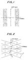
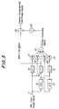
- Figs. 1 and 2 are schematic views showing two-dimensional frequency charts for explaining a principal conception of the contour correcting method according to the invention.
- a horizontal frequency is plotted on a horizontal axis representing the frequency of the color television signal
- a vertical frequency representing the spatial frequency of the television signal is plotted on a vertical axis
- an origin is plotted on a center.
- the vertical frequency is represented by cycle per height (cpH).
- Such a frequency characteristic chart is also called a circular zone plate chart and has been widely used for estimating a quality of a displayed image.
- a color subcarrier frequency f sc (284-1/4)f H +25Hz
- f sc 4.43361875 MHz. Therefore, regions in which undesired cross color occurs appear discretely as illustrated by circles in Figs. 1 and 2.
- regions in which a high visual effect of the contour enhancement can be attained appear in crosshatched band-like regions. It should be noted that the cross color regions are included within the high visual effect regions. In known contour correcting methods, the contour enhancement is carried out in the high visual effect regions, and thus the cross color generating regions are also enhanced.
- a two dimensional contour enhancement is carried out along a plurality of lines L on the two dimensional frequency chart as shown in Fig. 2.
- Said lines L do not pass through the origin O and intersect with each other at substantially middle points between successive cross color generating regions denoted by circles which appear discretely along lines parallel with the vertical axis and passing through color subcarrier frequency points of 4.43 MHz on both sides of the origin on the horizontal axis. Therefore, according to the invention, the two-dimensional contour enhancement of high visual effect can be performed in frequency regions of 3-4 MHz, while the contour enhancement is not effected in the cross color generating regions.
- Fig. 3 is a block diagram showing an embodiment of the contour correcting apparatus according to the invention.
- a PAL system color image signal whose contour is to be corrected.
- the input color image signal is divided into a first and a second color image signal.
- the first color image signal is supplied to a first two-line (2H) delay circuit 12 to derive a two-line delayed color image signal.
- H is a horizontal period and amounts to 64 micro seconds in the PAL system.
- the thus obtained 2H delayed color image signal is supplied to a second 2H delay circuit 13 to derive a four-line (4H) delayed color image signal.
- the second input color image signal is further divided into two color image signals, and one of them is supplied to a third 2T delay circuit 14 to derive a color image signal delayed by a period of 2T, wherein T is represented by 1/2f sc , while fsc is a color subcarrier frequency.
- T is represented by 1/2f sc
- fsc is a color subcarrier frequency.
- the period T amounts to about 113 nano seconds.
- the 4H delayed color image signal derived from the second 2H delay circuit 13 is divided into two signals, and one of them is supplied to a fourth 2T delay circuit 15 to produce a 2H+2T delayed color image signal.
- the 2H delayed color image signal derived from the first 2H delay circuit 12 is supplied to a fifth 1T delay circuit 16 to derive a 2H+T delayed color image signal.
- the 2T delayed color image signal derived from the third 2T delay circuit 14 is supplied to a first gain adjusting circuit 17, in which a polarity of the color image signal is inverted and a gain of the color image signal is reduced to a fourth of that of the input color image signal supplied to the input terminal 11.
- the input color image signal is supplied to a second gain adjusting circuit 18, in which a polarity is inverted and a gain is reduced to a fourth.
- the 4H+2T delayed color image signal derived from the fourth 2T delay circuit 15 is supplied to a third gain adjusting circuit 19 and a polarity of the color image signal is inverted and a gain is reduced to a fourth of that of the input color image signal.
- the 4H delayed color image signal derived from the second 2H delay circuit 13 is supplied to a fourth gain adjusting circuit 20, in which a polarity is inverted and a gain is decreased into a fourth of the input color image signal.
- the color image signals each having the inverted polarity and the gain reduced to a fourth of that of the input color image signal appearing at the input terminal 11 are then supplied to a second mixing circuit 21 together with the 2H+1T delayed color image signal derived from the fifth 1T delay circuit 16 without inverting a polarity with a gain of 1. It should be noted that the 2H+1T delayed color image signal is used as a main color image signal. Then, the mixing circuit 21 produces a contour correcting signal for enhancing a contour in a frequency region of 3-4 MHz, while the contour enhancement in the cross color generating regions can be effectively avoided.
- the main color image signal obtained by delaying the input color image signal by 2H by the first 2H delay circuit 12 and by delaying the 2H delayed color image signal by 1T by the fifth 1T delay circuit 16 is supplied to a second mixing circuit 22 to which the above mentioned contour correcting signal derived from the first mixing circuit 21 is also supplied via a fifth gain adjusting circuit 23. In this manner, from the second mixing circuit 22, there is derived a contour corrected PAL color image signal.
- the two-dimensional contour enhancement is carried out along cosine curves having crests on said lines and bottoms represented by the following coordinates: (n1/(2 ⁇ T), 625 ⁇ n2/8), wherein
- Fig. 4 is a block diagram showing an embodiment of the contour correcting apparatus according to the invention for use in the NTSC color television system.
- the contour correcting apparatus of the present embodiment is substantially identical with the previous embodiment illustrated in Fig. 3 and portions similar to those shown in Fig. 3 are denoted by the same reference numerals.
- the first and second 2H delay circuits 12 and 13 shown in Fig. 3 are replaced by first and second 1H delay circuits 32 and 33, respectively.
- the NTSC color television signal is treated, so that a delay time H of the first and second 1H delay circuits 32 and 33 are set to 64 micro seconds, a delay time of the third and fourth 2T delay circuits 14 and 15 is set to about 280 nano seconds, and a delay time of the fifth 1T delay circuit 16 is set to about 140 nano seconds.
- the lines along which the two-dimensional contour enhancement is carried out are set to lines which cross with each other at a middle of successive cross color generating regions and pass through points P on the vertical axis at which lines connecting said cross color generating regions to corresponding cross color generating regions which are symmetric to said successive cross color generating regions with respect to the vertical axis.
- the two-dimensional contour enhancement may be performed along lines which pass through points Q which situate externally with respect to the points P as illustrated in Fig. 5.
- the two-dimensional contour enhancement can be effected by escaping the cross color generating regions, the contour enhancement can be performed in the frequency regions 1-3 MHz in which the visual effect of the contour enhancement is highest.
- the cross color can be suppressed in the PAL system in which no effective cross color suppressing means has been developed on a receiver side.
- the cross color in a region in which the cross color could not be suppressed by known means can be effectively suppressed and the contour correction can be applied in regardless of receivers.
Landscapes
- Engineering & Computer Science (AREA)
- Multimedia (AREA)
- Signal Processing (AREA)
- Processing Of Color Television Signals (AREA)
- Picture Signal Circuits (AREA)
Claims (7)
- Ein Verfahren zum Korrigieren einer Kontur eines Farbfernsehsignales mit Berücksichtigen eines zweidimensionalen Frequenzcharakteristikdiagramms mit einem Ursprung an einem Mittelpunkt, einer horizontalen Achse einer horizontalen Frequenz des Farbfernsehsignales und einer vertikalen Achse einer vertikalen räumlichen Frequenz des Fernsehsignales, wobei eine zweidimensionale Konturverbesserung entlang einer Vielzahl von Linien (L) auf dem zweidimensionalen Frequenzdiagramm ausgeführt wird, wobei die Linien (L) nicht durch den Ursprung verlaufen und sich einander an Punkten schneiden, die im wesentlichen in der Mitte zwischen aufeinanderfolgenden Kreuzfarben erzeugenden Bereichen liegen, die entlang von Linien parallel zu der vertikalen Achse diskret auftreten und durch Farbzwischenträgerfrequenzpunkte auf beiden Seiten des Ursprunges auf der horizontalen Achse verlaufen.
- Ein Verfahren gemäß Anspruch 1, bei dem die Linien (L) durch Punkte (P) verlaufen, die an Schnittpunkten zwischen der vertikalen Achse und Linien liegen, die jeden der Kreuzfarben erzeugenden Bereiche mit entsprechenden Kreuzfarben erzeugenden Bereichen verbinden, die zu den Kreuzfarben erzeugenden Bereichen relativ zu der vertikalen Achse symmetrisch angeordnet sind.
- Ein Verfahren gemäß Anspruch 1, bei dem die Linien (L) durch Punkte (Q) verlaufen, die an Schnittpunkten zwischen der vertikalen Achse und Linien liegen, die jeden zweiten der aufeinanderfolgenden Kreuzfarben erzeugenden Bereiche mit entsprechenden Kreuzfarben erzeugenden Bereichen verbinden, die symmetrisch zu den Kreuzfarben erzeugenden Bereichen relativ zu der vertikalen Achse symmetrisch sind.
- Ein Verfahren gemäß Anspruch 1, bei dem die zweidimensionale Konturverbesserung für ein PAL-System-Farbfernsehsignal entlang von Linien (L) ausgeführt wird, die durch Punkte verlaufen, die durch (m/(2xT), 625xn/8) ausgedrückt sind, wobei T durch 1/2fsc gegeben ist, m = 0, ±2, ±4, ±6 --- und n = ±1, ±3, ±5, ±7 ---, und Steigungen von ± 625xT/4 aufweisen, wenn eine Zwischenträgerfrequenz durch fsc angegeben ist.
- Ein Verfahren gemäß Anspruch 1, bei dem die zweidimensionale Konturverbesserung für ein PAL-System-Farbfernsehsignal entlang von Linien (L) ausgeführt wird, die durch Punkte verlaufen, die durch (m/(2xT), 625xn/8) ausgedrückt sind, wobei T durch 1/2fsc gegeben ist, m = 0, ±2, ±4, ±6 --- und n = ±1, ±3, ±5, ±7 ---, und Steigungen von ± 625xT/2 aufweisen, wenn eine Zwischenträgerfrequenz durch fsc angegeben ist.
- Eine Vorrichtung zum Korrigieren einer Kontur eines Farbfernsehsignales des PAL-Systems, mit:einer ersten Verzögerungseinrichtung (12) zum Verzögern eines Eingangsfarbbildsignales um eine Zeitdauer für zwei Linien, um ein um zwei Linien verzögertes Farbbildsignal zu erzeugen,einer zweiten Verzögerungseinrichtung (13) zum Verzögern des um zwei Linien verzögerten Farbbildsignales um eine Zeitdauer für zwei Linien, um ein um vier Linien verzögertes Farbbildsignal zu erhalten,einer dritten Verzögerungseinrichtung (14) zum Verzögern des Eingangsfarbbildsignales um 2T, um ein um 2T verzögertes Farbbildsignal zu erhalten, wobei T=1/2fsc und fsc eine Farbzwischenträgerfrequenz ist,einer vierten Verzögerungseinrichtung (15) zum Verzögern des von der zweiten Verzögerungseinrichtung erhaltenen um vier Linien verzögerten Farbbildsignales um 2T, um ein Farbbildsignal zu erzeugen, das um vier Linien plus 2T verzögert ist,einer fünften Verzögerungseinrichtung (16), um das um zwei Linien verzögerte Farbbildsignal um T zu verzögern, um ein Farbbildsignal zu erzeugen, das um zwei Linien plus T verzögert ist,einer ersten Mischeinrichtung (17, 18, 19, 20, 21, 23) zum Mischen des um zwei Linien verzögerten Farbbildsignales von der ersten Verzögerungseinrichtung (12), des um vier Linien verzögerten Farbbildsignales von der zweiten Verzögerungseinrichtung (13), des um 2T verzögerten Farbbildsignales von der dritten Verzögerungseinrichtung (14), des um vier Linien plus 2T verzögerten Farbbildsignales von der vierten Verzögerungseinrichtung (15) und des um zwei Linien plus T verzögerten Farbbildsignales von der fünften Verzögerungseinrichtung (16) in einem vorbestimmten Verhältnis, um ein Konturkorrektursignal zu erhalten, undeiner zweiten Mischeinrichtung (22) zum Mischen des Konturkorrektursignales mit dem Eingangsfarbbildsignal, um ein zweidimensionales Kontur korrigiertes Farbbildsignal zu erhalten, indem Kreuzfarben erzeugende Bereiche vermieden werden.
- Eine Vorrichtung zum Korrigieren einer Kontur eines Farbbildsignales des NTSC-Systems, mit:einer ersten Verzögerungseinrichtung (32) zum Verzögern eines Eingangsfarbbildsignales um eine Periode für eine Linie, um ein um eine Linie verzögertes Farbbildsignal zu erzeugen,einer zweiten Verzögerungseinrichtung (33) zum Verzögern des um eine Linie verzögerten Farbbildsignales um eine Periode für eine Linie, um ein um zwei Linien verzögertes Farbbildsignal zu erhalten,einer dritten Verzögerungseinrichtung (14), um das Eingangsfarbbildsignal um 2T zu verzögern, um ein um 2T verzögertes Farbbildsignal zu erhalten, wobei T=1/2fsc und fsc eine Farbzwischenträgerfrequenz ist,einer vierten Verzögerungseinrichtung (15) zum Verzögern des von der zweiten Verzögerungseinrichtung erhaltenen um zwei Linien verzögerten Farbbildsignales um 2T, um ein Farbbildsignal zu erzeugen, das um zwei Linien plus 2T verzögert ist,einer fünften Verzögerungseinrichtung (16) zum Verzögern des um eine Linie verzögerten Farbbildsignales von der ersten Verzögerungseinrichtung um 2T, um ein Farbbildsignal zu erzeugen, das um eine Linie plus 2T verzögert ist,einer ersten Mischeinrichtung (17, 18, 19, 20, 21, 23) zum Mischen des um eine Linie verzögerten Farbbildsignales von der ersten Verzögerungseinrichtung (32), des um zwei Linien verzögerten Farbbildsignales von der zweiten Verzögerungseinrichtung (33), des um 2T verzögerten Farbbildsignales von der dritten Verzögerungseinrichtung (14), des um zwei Linien plus 2T verzögerten Farbbildsignales von der vierten Verzögerungseinrichtung (15) und des um eine Linie plus 2T verzögerten Farbbildsignales von der fünften Verzögerungseinrichtung (16) miteinander in einem vorbestimmten Verhältnis, um ein Konturkorrektursignal zu erhalten, undeiner zweiten Mischeinrichtung (22) zum Mischen des Konturkorrektursignales mit dem Eingangsfarbbildsignal, um ein Kontur korrigiertes Farbbildsignal zu erhalten, für das eine zweidimensionale Konturkorrektur durchgeführt wird, indem Kreuzfarben erzeugende Bereiche vermieden werden.
Applications Claiming Priority (3)
| Application Number | Priority Date | Filing Date | Title |
|---|---|---|---|
| JP11709195 | 1995-05-16 | ||
| JP7117091A JPH08317252A (ja) | 1995-05-16 | 1995-05-16 | 輪郭補正方法および装置 |
| JP117091/95 | 1995-05-16 |
Publications (3)
| Publication Number | Publication Date |
|---|---|
| EP0743799A2 EP0743799A2 (de) | 1996-11-20 |
| EP0743799A3 EP0743799A3 (de) | 1997-05-02 |
| EP0743799B1 true EP0743799B1 (de) | 2001-10-04 |
Family
ID=14703180
Family Applications (1)
| Application Number | Title | Priority Date | Filing Date |
|---|---|---|---|
| EP96106959A Expired - Lifetime EP0743799B1 (de) | 1995-05-16 | 1996-05-03 | Verfahren und Gerät zur Konturkorrektur von Farbbildsignalen |
Country Status (4)
| Country | Link |
|---|---|
| US (1) | US5731845A (de) |
| EP (1) | EP0743799B1 (de) |
| JP (1) | JPH08317252A (de) |
| DE (1) | DE69615608T2 (de) |
Families Citing this family (5)
| Publication number | Priority date | Publication date | Assignee | Title |
|---|---|---|---|---|
| JPH1146313A (ja) * | 1997-07-25 | 1999-02-16 | Fujitsu General Ltd | 輪郭強調回路 |
| JP3743235B2 (ja) * | 1999-10-30 | 2006-02-08 | 株式会社富士通ゼネラル | 輪郭強調方法及び回路 |
| JP4325388B2 (ja) * | 2003-12-12 | 2009-09-02 | ソニー株式会社 | 信号処理装置、画像表示装置および信号処理方法 |
| WO2006057403A1 (ja) * | 2004-11-29 | 2006-06-01 | Matsushita Electric Industrial Co., Ltd. | 画像処理装置 |
| CN115631112B (zh) * | 2022-11-18 | 2023-03-14 | 北京飞渡科技有限公司 | 一种基于深度学习的建筑轮廓矫正方法及装置 |
Family Cites Families (24)
| Publication number | Priority date | Publication date | Assignee | Title |
|---|---|---|---|---|
| JPS5642483A (en) * | 1979-09-17 | 1981-04-20 | Sony Corp | Luminance signal processing circuit for cross color suppression |
| JPS60253368A (ja) * | 1983-11-10 | 1985-12-14 | Dainippon Screen Mfg Co Ltd | 複製画像記録表示等に於けるjag除去方法 |
| US4677461A (en) * | 1984-07-26 | 1987-06-30 | Mitsubishi Denki Kabushiki Kaisha | Contour detecting filter |
| JPS61140280A (ja) * | 1984-12-12 | 1986-06-27 | Hitachi Ltd | 輪郭補償回路 |
| JPS627291A (ja) * | 1985-07-03 | 1987-01-14 | Mitsubishi Electric Corp | Pal適応型輪郭抽出フイルタ |
| JPS627292A (ja) * | 1985-07-03 | 1987-01-14 | Mitsubishi Electric Corp | Pal適応型輪郭抽出フイルタ |
| JPH0824347B2 (ja) * | 1986-05-12 | 1996-03-06 | 松下電器産業株式会社 | カラーテレビジョンカメラ用輪郭補正器 |
| JPH02285779A (ja) * | 1989-04-26 | 1990-11-26 | Matsushita Electric Ind Co Ltd | 輪郭補正器 |
| JP2773900B2 (ja) * | 1989-06-07 | 1998-07-09 | 池上通信機 株式会社 | Ntscカラーテレビジョンカメラの映像処理装置 |
| JP3202983B2 (ja) * | 1989-11-21 | 2001-08-27 | ソニー株式会社 | 固体撮像装置の信号処理回路 |
| JP2785213B2 (ja) * | 1989-11-24 | 1998-08-13 | ソニー株式会社 | 固体撮像装置の信号処理回路 |
| JPH03263977A (ja) * | 1989-11-27 | 1991-11-25 | Hitachi Ltd | テレビジョン受像機 |
| JP3038738B2 (ja) * | 1989-11-30 | 2000-05-08 | ソニー株式会社 | 固体撮像装置の信号処理回路 |
| JPH03289877A (ja) * | 1990-04-06 | 1991-12-19 | Sharp Corp | 輪郭補正回路 |
| JPH04100487A (ja) * | 1990-08-20 | 1992-04-02 | Ikegami Tsushinki Co Ltd | 輪郭補正方法 |
| JPH04126470A (ja) * | 1990-09-18 | 1992-04-27 | Toshiba Corp | 輪郭強調回路 |
| JPH04172096A (ja) * | 1990-11-05 | 1992-06-19 | Matsushita Electric Ind Co Ltd | Pal/ntsc両用3ライン・メディアン櫛形フィルタ |
| JPH04310092A (ja) * | 1991-04-09 | 1992-11-02 | Ikegami Tsushinki Co Ltd | カラーテレビジョン映像信号処理装置 |
| JP3303308B2 (ja) * | 1991-08-29 | 2002-07-22 | ソニー株式会社 | 映像信号処理装置 |
| FI923875A7 (fi) * | 1991-09-02 | 1993-03-03 | Philips Nv | Roerelseadaptiv bildsignalbehandling |
| JPH05103226A (ja) * | 1991-10-08 | 1993-04-23 | Matsushita Electric Ind Co Ltd | 輪郭平滑化回路 |
| KR950001577B1 (ko) * | 1992-02-21 | 1995-02-25 | 삼성전자주식회사 | 색분리 및 윤곽 보정회로 |
| JPH05328171A (ja) * | 1992-05-26 | 1993-12-10 | Victor Co Of Japan Ltd | 画像信号の輪郭強調回路 |
| JP3299810B2 (ja) * | 1993-04-28 | 2002-07-08 | 三菱電機株式会社 | 輝度信号色信号分離フィルタ |
-
1995
- 1995-05-16 JP JP7117091A patent/JPH08317252A/ja active Pending
-
1996
- 1996-04-29 US US08/639,448 patent/US5731845A/en not_active Expired - Lifetime
- 1996-05-03 EP EP96106959A patent/EP0743799B1/de not_active Expired - Lifetime
- 1996-05-03 DE DE69615608T patent/DE69615608T2/de not_active Expired - Lifetime
Also Published As
| Publication number | Publication date |
|---|---|
| DE69615608D1 (de) | 2001-11-08 |
| US5731845A (en) | 1998-03-24 |
| JPH08317252A (ja) | 1996-11-29 |
| EP0743799A2 (de) | 1996-11-20 |
| EP0743799A3 (de) | 1997-05-02 |
| DE69615608T2 (de) | 2002-04-18 |
Similar Documents
| Publication | Publication Date | Title |
|---|---|---|
| US5325186A (en) | Motion adaptive luminance signal and color signal separating filter | |
| EP0743799B1 (de) | Verfahren und Gerät zur Konturkorrektur von Farbbildsignalen | |
| US5107340A (en) | Digital video signal noise-reduction apparatus with high pass and low pass filter | |
| GB2271907A (en) | Adaptive chrominance signal separating apparatus | |
| KR940001441B1 (ko) | 운동 적응형 y/c분리기 | |
| EP0735783A2 (de) | Adaptiver Farbsignaldemodulator für das PAL-System | |
| JPH03274879A (ja) | テレビジョン方式 | |
| JPS612488A (ja) | 輝度信号搬送色信号分離装置 | |
| JPH02108390A (ja) | Palカラーテレビ信号の輝度信号・色信号分離回路 | |
| JPH0314393B2 (de) | ||
| JPS62128288A (ja) | 高精細テレビジヨン方式の動き検出回路 | |
| JPH01176190A (ja) | 動き適応型輝度信号色信号分離装置 | |
| JPH11313337A (ja) | 輪郭補正方法および装置 | |
| JP3024465B2 (ja) | フレーム間輝度信号・色信号分離装置 | |
| JPH06189335A (ja) | 3次元輝度信号色信号分離装置 | |
| JPS58145289A (ja) | 周波数分離形カラ−テレビジヨンカメラ | |
| JPS6320984A (ja) | テレビジョン信号帯域圧縮装置 | |
| JPH04252696A (ja) | 輝度信号色信号分離装置 | |
| JPS6153915B2 (de) | ||
| JPS61212184A (ja) | カラ−テレビジョン信号のy/c分離装置 | |
| JPH0813122B2 (ja) | 走査線補間回路 | |
| JP2557511B2 (ja) | テレビジョン表示画面の動き検出回路 | |
| JPH04189074A (ja) | エッジ補正回路 | |
| JPS62136191A (ja) | 信号処理回路 | |
| JPS62250779A (ja) | テレビジヨン信号多重方式 |
Legal Events
| Date | Code | Title | Description |
|---|---|---|---|
| PUAI | Public reference made under article 153(3) epc to a published international application that has entered the european phase |
Free format text: ORIGINAL CODE: 0009012 |
|
| AK | Designated contracting states |
Kind code of ref document: A2 Designated state(s): DE FR GB |
|
| PUAL | Search report despatched |
Free format text: ORIGINAL CODE: 0009013 |
|
| AK | Designated contracting states |
Kind code of ref document: A3 Designated state(s): DE FR GB |
|
| 17P | Request for examination filed |
Effective date: 19970602 |
|
| 17Q | First examination report despatched |
Effective date: 19990707 |
|
| GRAG | Despatch of communication of intention to grant |
Free format text: ORIGINAL CODE: EPIDOS AGRA |
|
| GRAG | Despatch of communication of intention to grant |
Free format text: ORIGINAL CODE: EPIDOS AGRA |
|
| GRAH | Despatch of communication of intention to grant a patent |
Free format text: ORIGINAL CODE: EPIDOS IGRA |
|
| GRAH | Despatch of communication of intention to grant a patent |
Free format text: ORIGINAL CODE: EPIDOS IGRA |
|
| GRAA | (expected) grant |
Free format text: ORIGINAL CODE: 0009210 |
|
| AK | Designated contracting states |
Kind code of ref document: B1 Designated state(s): DE FR GB |
|
| REF | Corresponds to: |
Ref document number: 69615608 Country of ref document: DE Date of ref document: 20011108 |
|
| REG | Reference to a national code |
Ref country code: GB Ref legal event code: IF02 |
|
| ET | Fr: translation filed | ||
| PLBE | No opposition filed within time limit |
Free format text: ORIGINAL CODE: 0009261 |
|
| STAA | Information on the status of an ep patent application or granted ep patent |
Free format text: STATUS: NO OPPOSITION FILED WITHIN TIME LIMIT |
|
| 26N | No opposition filed | ||
| REG | Reference to a national code |
Ref country code: FR Ref legal event code: ST Effective date: 20100129 |
|
| PG25 | Lapsed in a contracting state [announced via postgrant information from national office to epo] |
Ref country code: FR Free format text: LAPSE BECAUSE OF NON-PAYMENT OF DUE FEES Effective date: 20090602 |
|
| PGFP | Annual fee paid to national office [announced via postgrant information from national office to epo] |
Ref country code: FR Payment date: 20080429 Year of fee payment: 13 |
|
| PGFP | Annual fee paid to national office [announced via postgrant information from national office to epo] |
Ref country code: GB Payment date: 20150529 Year of fee payment: 20 Ref country code: DE Payment date: 20150528 Year of fee payment: 20 |
|
| REG | Reference to a national code |
Ref country code: DE Ref legal event code: R071 Ref document number: 69615608 Country of ref document: DE |
|
| REG | Reference to a national code |
Ref country code: GB Ref legal event code: PE20 Expiry date: 20160502 |
|
| PG25 | Lapsed in a contracting state [announced via postgrant information from national office to epo] |
Ref country code: GB Free format text: LAPSE BECAUSE OF EXPIRATION OF PROTECTION Effective date: 20160502 |