EP0733798B1 - Kraftstoff-Einspritzvorrichtung nach dem Festkörper-Energiespeicherprinzip für Brennkraftmaschinen - Google Patents
Kraftstoff-Einspritzvorrichtung nach dem Festkörper-Energiespeicherprinzip für Brennkraftmaschinen Download PDFInfo
- Publication number
- EP0733798B1 EP0733798B1 EP96109438A EP96109438A EP0733798B1 EP 0733798 B1 EP0733798 B1 EP 0733798B1 EP 96109438 A EP96109438 A EP 96109438A EP 96109438 A EP96109438 A EP 96109438A EP 0733798 B1 EP0733798 B1 EP 0733798B1
- Authority
- EP
- European Patent Office
- Prior art keywords
- valve
- cylinder
- bore
- tappet
- piston
- Prior art date
- Legal status (The legal status is an assumption and is not a legal conclusion. Google has not performed a legal analysis and makes no representation as to the accuracy of the status listed.)
- Expired - Lifetime
Links
- 239000000446 fuel Substances 0.000 title claims abstract description 59
- 238000002347 injection Methods 0.000 title claims abstract description 48
- 239000007924 injection Substances 0.000 title claims abstract description 48
- 238000002485 combustion reaction Methods 0.000 title description 3
- 239000007787 solid Substances 0.000 title 1
- 230000006835 compression Effects 0.000 claims description 10
- 238000007906 compression Methods 0.000 claims description 10
- 230000001133 acceleration Effects 0.000 claims description 7
- 238000013016 damping Methods 0.000 claims description 5
- 238000004146 energy storage Methods 0.000 claims description 4
- 230000000694 effects Effects 0.000 claims description 3
- 230000002093 peripheral effect Effects 0.000 claims description 3
- 239000011324 bead Substances 0.000 claims description 2
- 238000007142 ring opening reaction Methods 0.000 claims description 2
- 230000000284 resting effect Effects 0.000 claims 3
- 238000005192 partition Methods 0.000 claims 1
- 238000000034 method Methods 0.000 description 4
- 239000007921 spray Substances 0.000 description 3
- 238000005507 spraying Methods 0.000 description 3
- 238000004519 manufacturing process Methods 0.000 description 2
- 206010015137 Eructation Diseases 0.000 description 1
- 230000002411 adverse Effects 0.000 description 1
- 208000027687 belching Diseases 0.000 description 1
- 238000011161 development Methods 0.000 description 1
- 230000018109 developmental process Effects 0.000 description 1
- 238000006073 displacement reaction Methods 0.000 description 1
- 230000005284 excitation Effects 0.000 description 1
- 210000003746 feather Anatomy 0.000 description 1
- 239000002828 fuel tank Substances 0.000 description 1
- 239000007788 liquid Substances 0.000 description 1
- 230000000644 propagated effect Effects 0.000 description 1
- 238000011144 upstream manufacturing Methods 0.000 description 1
Images


Classifications
-
- F—MECHANICAL ENGINEERING; LIGHTING; HEATING; WEAPONS; BLASTING
- F02—COMBUSTION ENGINES; HOT-GAS OR COMBUSTION-PRODUCT ENGINE PLANTS
- F02M—SUPPLYING COMBUSTION ENGINES IN GENERAL WITH COMBUSTIBLE MIXTURES OR CONSTITUENTS THEREOF
- F02M69/00—Low-pressure fuel-injection apparatus ; Apparatus with both continuous and intermittent injection; Apparatus injecting different types of fuel
- F02M69/46—Details, component parts or accessories not provided for in, or of interest apart from, the apparatus covered by groups F02M69/02 - F02M69/44
- F02M69/462—Arrangement of fuel conduits, e.g. with valves for maintaining pressure in the pipes after the engine being shut-down
-
- F—MECHANICAL ENGINEERING; LIGHTING; HEATING; WEAPONS; BLASTING
- F01—MACHINES OR ENGINES IN GENERAL; ENGINE PLANTS IN GENERAL; STEAM ENGINES
- F01M—LUBRICATING OF MACHINES OR ENGINES IN GENERAL; LUBRICATING INTERNAL COMBUSTION ENGINES; CRANKCASE VENTILATING
- F01M1/00—Pressure lubrication
- F01M1/02—Pressure lubrication using lubricating pumps
-
- F—MECHANICAL ENGINEERING; LIGHTING; HEATING; WEAPONS; BLASTING
- F02—COMBUSTION ENGINES; HOT-GAS OR COMBUSTION-PRODUCT ENGINE PLANTS
- F02D—CONTROLLING COMBUSTION ENGINES
- F02D33/00—Controlling delivery of fuel or combustion-air, not otherwise provided for
- F02D33/003—Controlling the feeding of liquid fuel from storage containers to carburettors or fuel-injection apparatus ; Failure or leakage prevention; Diagnosis or detection of failure; Arrangement of sensors in the fuel system; Electric wiring; Electrostatic discharge
- F02D33/006—Controlling the feeding of liquid fuel from storage containers to carburettors or fuel-injection apparatus ; Failure or leakage prevention; Diagnosis or detection of failure; Arrangement of sensors in the fuel system; Electric wiring; Electrostatic discharge depending on engine operating conditions, e.g. start, stop or ambient conditions
-
- F—MECHANICAL ENGINEERING; LIGHTING; HEATING; WEAPONS; BLASTING
- F02—COMBUSTION ENGINES; HOT-GAS OR COMBUSTION-PRODUCT ENGINE PLANTS
- F02D—CONTROLLING COMBUSTION ENGINES
- F02D41/00—Electrical control of supply of combustible mixture or its constituents
- F02D41/20—Output circuits, e.g. for controlling currents in command coils
-
- F—MECHANICAL ENGINEERING; LIGHTING; HEATING; WEAPONS; BLASTING
- F02—COMBUSTION ENGINES; HOT-GAS OR COMBUSTION-PRODUCT ENGINE PLANTS
- F02M—SUPPLYING COMBUSTION ENGINES IN GENERAL WITH COMBUSTIBLE MIXTURES OR CONSTITUENTS THEREOF
- F02M37/00—Apparatus or systems for feeding liquid fuel from storage containers to carburettors or fuel-injection apparatus; Arrangements for purifying liquid fuel specially adapted for, or arranged on, internal-combustion engines
- F02M37/0047—Layout or arrangement of systems for feeding fuel
-
- F—MECHANICAL ENGINEERING; LIGHTING; HEATING; WEAPONS; BLASTING
- F02—COMBUSTION ENGINES; HOT-GAS OR COMBUSTION-PRODUCT ENGINE PLANTS
- F02M—SUPPLYING COMBUSTION ENGINES IN GENERAL WITH COMBUSTIBLE MIXTURES OR CONSTITUENTS THEREOF
- F02M37/00—Apparatus or systems for feeding liquid fuel from storage containers to carburettors or fuel-injection apparatus; Arrangements for purifying liquid fuel specially adapted for, or arranged on, internal-combustion engines
- F02M37/04—Feeding by means of driven pumps
- F02M37/08—Feeding by means of driven pumps electrically driven
-
- F—MECHANICAL ENGINEERING; LIGHTING; HEATING; WEAPONS; BLASTING
- F02—COMBUSTION ENGINES; HOT-GAS OR COMBUSTION-PRODUCT ENGINE PLANTS
- F02M—SUPPLYING COMBUSTION ENGINES IN GENERAL WITH COMBUSTIBLE MIXTURES OR CONSTITUENTS THEREOF
- F02M39/00—Arrangements of fuel-injection apparatus with respect to engines; Pump drives adapted to such arrangements
- F02M39/005—Arrangements of fuel feed-pumps with respect to fuel injection apparatus
-
- F—MECHANICAL ENGINEERING; LIGHTING; HEATING; WEAPONS; BLASTING
- F02—COMBUSTION ENGINES; HOT-GAS OR COMBUSTION-PRODUCT ENGINE PLANTS
- F02M—SUPPLYING COMBUSTION ENGINES IN GENERAL WITH COMBUSTIBLE MIXTURES OR CONSTITUENTS THEREOF
- F02M51/00—Fuel-injection apparatus characterised by being operated electrically
- F02M51/04—Pumps peculiar thereto
-
- F—MECHANICAL ENGINEERING; LIGHTING; HEATING; WEAPONS; BLASTING
- F02—COMBUSTION ENGINES; HOT-GAS OR COMBUSTION-PRODUCT ENGINE PLANTS
- F02M—SUPPLYING COMBUSTION ENGINES IN GENERAL WITH COMBUSTIBLE MIXTURES OR CONSTITUENTS THEREOF
- F02M55/00—Fuel-injection apparatus characterised by their fuel conduits or their venting means; Arrangements of conduits between fuel tank and pump F02M37/00
- F02M55/007—Venting means
-
- F—MECHANICAL ENGINEERING; LIGHTING; HEATING; WEAPONS; BLASTING
- F02—COMBUSTION ENGINES; HOT-GAS OR COMBUSTION-PRODUCT ENGINE PLANTS
- F02M—SUPPLYING COMBUSTION ENGINES IN GENERAL WITH COMBUSTIBLE MIXTURES OR CONSTITUENTS THEREOF
- F02M55/00—Fuel-injection apparatus characterised by their fuel conduits or their venting means; Arrangements of conduits between fuel tank and pump F02M37/00
- F02M55/02—Conduits between injection pumps and injectors, e.g. conduits between pump and common-rail or conduits between common-rail and injectors
-
- F—MECHANICAL ENGINEERING; LIGHTING; HEATING; WEAPONS; BLASTING
- F02—COMBUSTION ENGINES; HOT-GAS OR COMBUSTION-PRODUCT ENGINE PLANTS
- F02M—SUPPLYING COMBUSTION ENGINES IN GENERAL WITH COMBUSTIBLE MIXTURES OR CONSTITUENTS THEREOF
- F02M57/00—Fuel-injectors combined or associated with other devices
- F02M57/02—Injectors structurally combined with fuel-injection pumps
- F02M57/022—Injectors structurally combined with fuel-injection pumps characterised by the pump drive
- F02M57/027—Injectors structurally combined with fuel-injection pumps characterised by the pump drive electric
-
- F—MECHANICAL ENGINEERING; LIGHTING; HEATING; WEAPONS; BLASTING
- F02—COMBUSTION ENGINES; HOT-GAS OR COMBUSTION-PRODUCT ENGINE PLANTS
- F02M—SUPPLYING COMBUSTION ENGINES IN GENERAL WITH COMBUSTIBLE MIXTURES OR CONSTITUENTS THEREOF
- F02M59/00—Pumps specially adapted for fuel-injection and not provided for in groups F02M39/00 -F02M57/00, e.g. rotary cylinder-block type of pumps
- F02M59/38—Pumps characterised by adaptations to special uses or conditions
-
- F—MECHANICAL ENGINEERING; LIGHTING; HEATING; WEAPONS; BLASTING
- F02—COMBUSTION ENGINES; HOT-GAS OR COMBUSTION-PRODUCT ENGINE PLANTS
- F02M—SUPPLYING COMBUSTION ENGINES IN GENERAL WITH COMBUSTIBLE MIXTURES OR CONSTITUENTS THEREOF
- F02M61/00—Fuel-injectors not provided for in groups F02M39/00 - F02M57/00 or F02M67/00
- F02M61/04—Fuel-injectors not provided for in groups F02M39/00 - F02M57/00 or F02M67/00 having valves, e.g. having a plurality of valves in series
- F02M61/047—Fuel-injectors not provided for in groups F02M39/00 - F02M57/00 or F02M67/00 having valves, e.g. having a plurality of valves in series the valves being formed by deformable nozzle parts, e.g. flexible plates or discs with fuel discharge orifices
-
- F—MECHANICAL ENGINEERING; LIGHTING; HEATING; WEAPONS; BLASTING
- F02—COMBUSTION ENGINES; HOT-GAS OR COMBUSTION-PRODUCT ENGINE PLANTS
- F02M—SUPPLYING COMBUSTION ENGINES IN GENERAL WITH COMBUSTIBLE MIXTURES OR CONSTITUENTS THEREOF
- F02M61/00—Fuel-injectors not provided for in groups F02M39/00 - F02M57/00 or F02M67/00
- F02M61/04—Fuel-injectors not provided for in groups F02M39/00 - F02M57/00 or F02M67/00 having valves, e.g. having a plurality of valves in series
- F02M61/08—Fuel-injectors not provided for in groups F02M39/00 - F02M57/00 or F02M67/00 having valves, e.g. having a plurality of valves in series the valves opening in direction of fuel flow
-
- F—MECHANICAL ENGINEERING; LIGHTING; HEATING; WEAPONS; BLASTING
- F02—COMBUSTION ENGINES; HOT-GAS OR COMBUSTION-PRODUCT ENGINE PLANTS
- F02M—SUPPLYING COMBUSTION ENGINES IN GENERAL WITH COMBUSTIBLE MIXTURES OR CONSTITUENTS THEREOF
- F02M63/00—Other fuel-injection apparatus having pertinent characteristics not provided for in groups F02M39/00 - F02M57/00 or F02M67/00; Details, component parts, or accessories of fuel-injection apparatus, not provided for in, or of interest apart from, the apparatus of groups F02M39/00 - F02M61/00 or F02M67/00; Combination of fuel pump with other devices, e.g. lubricating oil pump
- F02M63/06—Use of pressure wave generated by fuel inertia to open injection valves
-
- F—MECHANICAL ENGINEERING; LIGHTING; HEATING; WEAPONS; BLASTING
- F02—COMBUSTION ENGINES; HOT-GAS OR COMBUSTION-PRODUCT ENGINE PLANTS
- F02M—SUPPLYING COMBUSTION ENGINES IN GENERAL WITH COMBUSTIBLE MIXTURES OR CONSTITUENTS THEREOF
- F02M69/00—Low-pressure fuel-injection apparatus ; Apparatus with both continuous and intermittent injection; Apparatus injecting different types of fuel
- F02M69/16—Low-pressure fuel-injection apparatus ; Apparatus with both continuous and intermittent injection; Apparatus injecting different types of fuel characterised by means for metering continuous fuel flow to injectors or means for varying fuel pressure upstream of continuously or intermittently operated injectors
- F02M69/18—Low-pressure fuel-injection apparatus ; Apparatus with both continuous and intermittent injection; Apparatus injecting different types of fuel characterised by means for metering continuous fuel flow to injectors or means for varying fuel pressure upstream of continuously or intermittently operated injectors the means being metering valves throttling fuel passages to injectors or by-pass valves throttling overflow passages, the metering valves being actuated by a device responsive to the engine working parameters, e.g. engine load, speed, temperature or quantity of air
- F02M69/24—Low-pressure fuel-injection apparatus ; Apparatus with both continuous and intermittent injection; Apparatus injecting different types of fuel characterised by means for metering continuous fuel flow to injectors or means for varying fuel pressure upstream of continuously or intermittently operated injectors the means being metering valves throttling fuel passages to injectors or by-pass valves throttling overflow passages, the metering valves being actuated by a device responsive to the engine working parameters, e.g. engine load, speed, temperature or quantity of air the device comprising a member for transmitting the movement of the air throttle valve actuated by the operator to the valves controlling fuel passages
-
- F—MECHANICAL ENGINEERING; LIGHTING; HEATING; WEAPONS; BLASTING
- F02—COMBUSTION ENGINES; HOT-GAS OR COMBUSTION-PRODUCT ENGINE PLANTS
- F02M—SUPPLYING COMBUSTION ENGINES IN GENERAL WITH COMBUSTIBLE MIXTURES OR CONSTITUENTS THEREOF
- F02M69/00—Low-pressure fuel-injection apparatus ; Apparatus with both continuous and intermittent injection; Apparatus injecting different types of fuel
- F02M69/30—Low-pressure fuel-injection apparatus ; Apparatus with both continuous and intermittent injection; Apparatus injecting different types of fuel characterised by means for facilitating the starting-up or idling of engines or by means for enriching fuel charge, e.g. below operational temperatures or upon high power demand of engines
- F02M69/34—Low-pressure fuel-injection apparatus ; Apparatus with both continuous and intermittent injection; Apparatus injecting different types of fuel characterised by means for facilitating the starting-up or idling of engines or by means for enriching fuel charge, e.g. below operational temperatures or upon high power demand of engines with an auxiliary fuel circuit supplying fuel to the engine, e.g. with the fuel pump outlet being directly connected to injection nozzles
-
- F—MECHANICAL ENGINEERING; LIGHTING; HEATING; WEAPONS; BLASTING
- F02—COMBUSTION ENGINES; HOT-GAS OR COMBUSTION-PRODUCT ENGINE PLANTS
- F02M—SUPPLYING COMBUSTION ENGINES IN GENERAL WITH COMBUSTIBLE MIXTURES OR CONSTITUENTS THEREOF
- F02M69/00—Low-pressure fuel-injection apparatus ; Apparatus with both continuous and intermittent injection; Apparatus injecting different types of fuel
- F02M69/46—Details, component parts or accessories not provided for in, or of interest apart from, the apparatus covered by groups F02M69/02 - F02M69/44
-
- F—MECHANICAL ENGINEERING; LIGHTING; HEATING; WEAPONS; BLASTING
- F02—COMBUSTION ENGINES; HOT-GAS OR COMBUSTION-PRODUCT ENGINE PLANTS
- F02D—CONTROLLING COMBUSTION ENGINES
- F02D41/00—Electrical control of supply of combustible mixture or its constituents
- F02D41/20—Output circuits, e.g. for controlling currents in command coils
- F02D2041/202—Output circuits, e.g. for controlling currents in command coils characterised by the control of the circuit
- F02D2041/2058—Output circuits, e.g. for controlling currents in command coils characterised by the control of the circuit using information of the actual current value
-
- F—MECHANICAL ENGINEERING; LIGHTING; HEATING; WEAPONS; BLASTING
- F02—COMBUSTION ENGINES; HOT-GAS OR COMBUSTION-PRODUCT ENGINE PLANTS
- F02D—CONTROLLING COMBUSTION ENGINES
- F02D41/00—Electrical control of supply of combustible mixture or its constituents
- F02D41/20—Output circuits, e.g. for controlling currents in command coils
- F02D2041/2068—Output circuits, e.g. for controlling currents in command coils characterised by the circuit design or special circuit elements
- F02D2041/2075—Type of transistors or particular use thereof
-
- F—MECHANICAL ENGINEERING; LIGHTING; HEATING; WEAPONS; BLASTING
- F02—COMBUSTION ENGINES; HOT-GAS OR COMBUSTION-PRODUCT ENGINE PLANTS
- F02M—SUPPLYING COMBUSTION ENGINES IN GENERAL WITH COMBUSTIBLE MIXTURES OR CONSTITUENTS THEREOF
- F02M37/00—Apparatus or systems for feeding liquid fuel from storage containers to carburettors or fuel-injection apparatus; Arrangements for purifying liquid fuel specially adapted for, or arranged on, internal-combustion engines
- F02M37/04—Feeding by means of driven pumps
- F02M37/08—Feeding by means of driven pumps electrically driven
- F02M2037/085—Electric circuits therefor
-
- F—MECHANICAL ENGINEERING; LIGHTING; HEATING; WEAPONS; BLASTING
- F02—COMBUSTION ENGINES; HOT-GAS OR COMBUSTION-PRODUCT ENGINE PLANTS
- F02M—SUPPLYING COMBUSTION ENGINES IN GENERAL WITH COMBUSTIBLE MIXTURES OR CONSTITUENTS THEREOF
- F02M2200/00—Details of fuel-injection apparatus, not otherwise provided for
- F02M2200/24—Fuel-injection apparatus with sensors
-
- F—MECHANICAL ENGINEERING; LIGHTING; HEATING; WEAPONS; BLASTING
- F02—COMBUSTION ENGINES; HOT-GAS OR COMBUSTION-PRODUCT ENGINE PLANTS
- F02M—SUPPLYING COMBUSTION ENGINES IN GENERAL WITH COMBUSTIBLE MIXTURES OR CONSTITUENTS THEREOF
- F02M2200/00—Details of fuel-injection apparatus, not otherwise provided for
- F02M2200/40—Fuel-injection apparatus with fuel accumulators, e.g. a fuel injector having an integrated fuel accumulator
Definitions
- the invention relates to a device for injecting Fuel for internal combustion engines in the preamble of the claim 1 specified Art.
- Injection devices their electrically operated reciprocating pumps according to the so-called solid-state energy storage principle work, have a delivery piston or cylinder on accelerated along a certain path almost without resistance, usually fuel is moved before the delivery pressure is built up to spray the fuel through the injector is required. That way before the actual pressure build-up required for injection kinetic energy absorbed or stored, which then suddenly converted into a pressure increase in the fuel becomes.
- a so-called pump-nozzle element known from DD-PS 120 514, that according to the solid-state energy storage principle works, has the receiving piston of the injection pump Fuel delivery chamber axially parallel in a first section arranged grooves in the inner wall through which Fuel can drain to the back of the delivery piston, though the delivery piston starts to move without it becoming one noticeable pressure build-up in the fuel.
- the subsequent second section of the fuel delivery chamber is the actual pressure chamber that has no grooves. If the accelerated delivery piston enters this pressure chamber, the incompressible fuel suddenly slows it down, whereby the stored kinetic energy into one Pressure surge is converted by the resistance of the injector is overcome so that it can be used to cumshot Fuel is coming.
- the disadvantage here is that when immersed of the delivery piston in the second section of the delivery chamber due to unfavorable gap conditions, namely one relative large gap width and a relatively small gap length, noticeable high pressure drops occur, in particular the possible Reduce the speed and pressure level of the pressure build-up and thus adversely affect the spraying process.
- the pressure drops are caused by fuel flowing out of the pressure chamber into the pressure antechamber (first section of the fuel delivery chamber) caused.
- this disadvantage should be avoided, by storing an impact body in the pressure chamber of the delivery cylinder on the piston accelerated almost without resistance hits, so that the pressure loss during pressure build-up by a relatively large gap length despite a relatively large gap width (large Manufacturing tolerances) between the impact body and the pressure chamber inner wall surface can be kept reasonably small.
- the disadvantage here is that it is due to the impact process there is a high level of wear on the bodies that meet.
- the impact body is caused by the impact in longitudinal vibrations offset, which are transferred to the fuel and there the injection process as high-frequency pressure vibrations to disturb.
- a particular disadvantage of these known solid-state energy storage injection devices is that the injection process is controllable only to a very limited extent, that is to say only very limitedly can be adapted to the load conditions of the engine.
- a cross hole in the pump cylinder allows fuel to drain to the back of the Cylinders when storing energy.
- Driving over the front edge of the piston with the bore leads to pressure build-up and thus to spraying of fuel. In this case, too, there are high gap losses when pressure builds up.
- the object of the invention is an inexpensive, easy to manufacture Device for injecting fuel at the beginning to create the type mentioned, with the noticeable loss of pressure wear-free during pressure build-up and precisely controllable depending on the load Fuel can be injected and in particular is suitable for high-speed internal combustion engines.
- the fuel injection device has a Reciprocating pump, in which a valve is integrated, which the uninterrupted acceleration interrupts, so that a pressure surge is generated with which fuel is sprayed.
- the valve is outside the leading liquid-tight contact area between a piston element and a piston cylinder Reciprocating pump arranged so that without noticeable pressure drops the pressure can be built up without wear, depending on the load precisely controllable fuel is sprayable and the entire device is very simple.
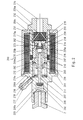
- Figure 1 shows a compact design of the invention electrically operated piston pump with integrated stop valve. It is in a cylindrical multi-part housing 200 in one of an outer jacket 200a and a cylindrical inner jacket 200b and a tank side End wall 200c and a pressure line end wall 200d delimited interior 202, a coil 201 is arranged.
- the from Inner jacket 200b surrounding cylindrical interior 202 of the housing 200 is extended by a radially inward Ring 203 in a tank side and a pressure line side Interior area divided.
- Pressure line side is against Ring edge of the ring 203 a positive and firm in this Set inside ring bead 204 of a piston 205, the piston 205 spacing the ring opening 206 of the ring 203 reaches through and into the tank-side area of the interior 202 protrudes.
- the piston 205 is from a through bore 207 penetrates, which extends in the tank-side end region of the piston is formed and there stores a valve 208, which by a Coil spring 209 towards the tank side for the closed position is pressed against a valve seat 209a, through with the Exposure to pressure from the tank side opened can be.
- a pump cylinder 210 of the reciprocating pump On the inside of the tank 202 of the interior 202 located part of the piston 205 sits positively and slidably a pump cylinder 210 of the reciprocating pump, which by a one end on the ring 203 and the other end on a ring step 212 of the cylinder 210 supporting coil spring 211 with its Tank-side end face 214 against a ring step 213 in Inner space 202 is pressed, with a protruding from the end face 214 Valve nozzle 215 with a radial distance a bit in the in this area radially narrowed interior 202a protrudes and where the end face of the cylinder 210 in the pressure line side Distance from the ring 203 is arranged and thus a movement space is created for the cylinder 210.
- the form-fitting on the Inner walls of the interior 202 are guided cylinders 210 has axially parallel, frontal open longitudinal grooves 216 in the Lateral surface, the function of which is explained below.
- the continuous through the pump cylinder 210, the piston 205 receiving bore 217 is stored on the tank side of the piston 205 upstream tappet valve, the tappet disc 218 at a distance from the face surface of the piston 205 in a short Hole extension is arranged and its pushrod 219th the narrowed bore 217a in the valve stub 215, against the Supporting inner wall of the bore 217a, reaches through and into the narrowed interior 202a protrudes.
- the plunger stem 219 still on Extends beyond the plate 220 and against the tank side Bottom surface 222 of the interior 202a abuts.
- the pestle handle 219 chosen so long that the plunger plate 218 from its Valve seat, the pressure line side opening 223 of the narrowed Bore 217a is lifted off, so that a certain gap "X" is formed whose meaning and purpose is explained below.
- a coil spring 224 stabilizes this position of the tappet valve in the shown idle position of the reciprocating pump, in which the spring 224 ends on the end face 214 of the Cylinder 210 and otherwise supported against the plate 220.
- the valve chamber 226 is located with one leading to the fuel tank Fuel line in connection (not shown); to the end wall 200d on the pressure line side or to an extended one A pressure line is attached to the inner wall 200b (not shown), which leads to the spray valve.
- Fuel line in connection (not shown); to the end wall 200d on the pressure line side or to an extended one
- a pressure line is attached to the inner wall 200b (not shown), which leads to the spray valve.
- the arrows drawn in FIG. 13 indicate the path of the fuel on.
- the reciprocating pump shown in Figure 1 works like follows.
- the cylinder 210 By energizing the coil 201, the cylinder 210 almost from the shown rest position towards the pressure line accelerated without resistance, from room 202 over the Grooves 216 and from the bore 217 or the tappet plate space Fuel flows out toward interior 202a.
- the accelerated Movement ends with the impact of the valve seat 223 the valve plate 218 abruptly, so that the stored energy of the Cylinder 210 on the fuel in the plunger vestibule is transmitted.
- the valve 208 is opened and the Pressure on the one in the bore 207 or in the pressure line Fuel propagated, causing a splash of Fuel is injected through the injector. If the excitement is not yet switched off, fuel is sprayed off for as long as how the cylinder is moved.
- the tappet valve 218, 219 is taken along by the cylinder 210 and a Vacuum in the interior 202, 202a and in the holes 225 and the anteroom of the valve chamber delimited by valve 229 226 so that the valve 229 is opened.
- the fuel flows coming from the tank through the peripheral grooves 230 in the valve plate 229, the anteroom of the valve chamber 226, the bores 225 and the Holes 221 in the plate 220 in the interior 202a and over the Grooves 216 in the interior 202.
- the spring 211 After switching off the excitation the spring 211 returns the cylinder to its rest or home position pushed back, previously the pushrod 219 hits against the bottom wall 222 and opens the tappet valve is so that fuel through the space between the Tappet stem and bore 217a in the plunger plate vestibule 217 can flow.
- the valve 208 remains closed. It works as a standing pressure valve and stops in between Injector (not shown) and the valve plate 208 located, filled with fuel a stand pressure in the Upright fuel, e.g. is higher than the vapor pressure of the Liquid at maximum temperature, so that Blistering can be prevented.
- Piston 205 formed integrally with the end wall 200d and the standing pressure valve 208, 209, which in a pipe socket 208a is housed, covers the mouth of the discharge line bore 207 going through the piston 205.
- the sliding pump cylinder 210 acting as an anchor is for one simple possibility of mounting the valve lifter 218, 219 constructed in several parts. Since the multiple parts are not essential to the invention is the structure of the cylinder 210 is not closer described.
- the plunger stem 219 is relatively short and can be over the tank-side end ring surface 214 of the cylinder 210 only by that Protrude valve clearance.
- the end ring surface 214 abuts in the area the end wall 200c against a plastic block stored there 231, which has through holes 232, the peripheral open into grooves 233, which with the tank-side interior 202 are connected, with 202 holes from the tank-side interior 234 to the enlarged bore area of bore 217 in Guide cylinder 210.
- the holes 232 open into the tank leading axial valve chamber 226, which in a pipe socket 226a is housed.
- the tappet valve 218, 219 not spring loaded. It works due to inertial forces, the plunger stem approximately form-fitting in the narrowed bore 217a sits.
- the tappet valve is positioned by the on the tappet plate 218 acting pressure prevailing in rooms 202, 217, 207 pressed against the plastic block 231. If the cylinder 210 accelerates, the tappet valve remains in this position until it is taken away from the valve seat 223. With the return movement of the armature cylinder 210, the plunger stem 219 abuts against the Plastic block 231 so that the tappet valve is back in its shown starting position arrives.
- the hole extension expediently forms the hole 217, in which the tappet plate 218 is received, on the pressure line side a ring stage 235, which is in the rest position of the Tappet valve only a short distance in front of tappet plate 218 is located and against which the plunger plate 218 hits when the Tappet due to inertia during the return movement of the cylinder 210 lifts off the valve seat and / or the valve from the plastic block 231 rebounded during the return movement of the cylinder 210 should be.
- Recesses 235a In the end face of the ring step 235 are Recesses 235a introduced, which has an unimpeded flow ensure the fuel. In this way is the rest position of the tappet valve ensured with simple means.
- the acceleration of the armature cylinder 210 flows in this embodiment of the injection pump fuel from the pressure line-side interior 202 via the grooves 216 in the Tank-side interior 202 and from the bores 207, 217 through the recesses 235a past the plunger plate 218 through the Valve seat opening in the bores 235 also in the tank side Interior 202.
- the displacement of the fuel is by the closing of the tappet valve 218, 219 suddenly interrupted, whereby the intended pressure surge is achieved.
- With the return movement of the armature cylinder 210 opens the tappet valve 218, 219 and the fuel flows in the opposite direction.
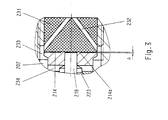
- the embodiment of the reciprocating pump according to FIGS. 2 and 3 can with a simply constructed effective anchor damping device be provided, which is shown in Fig. 4.
- the plunger stem 219 has one in its free end region Flange ring 219a on which the end face 214 a piece overlaps laterally and lie against the end face 214 can.
- Flange ring 219a In the surface of the plastic block 231 is one Flange ring 219a introduced corresponding recess 231a, in which the flange ring 219a fits approximately form-fitting, so that a piston-cylinder-shaped hydraulic damping device becomes.
- the thickness of the flange ring 219a is expediently somewhat executed greater than the depth of the recess 231a, so that the Front ring surface 214 in the rest position of the armature cylinder 210 remains at a distance from the surface of the plastic block 231 and support bars are not required.
- the pressure line side Interior 202 leads to the outside and a nozzle on the outside 237 is set with a through hole 238.
- a bore 236 the pressure line side Interior 202 leads to the outside and a nozzle on the outside 237 is set with a through hole 238.
- Through the Bore 236 and drain connector 237 can e.g. during the Start phase of the pump or motor fuel from the armature cylinder 210 are pumped out, so that the pump and / or the fuel Supply line of air bubbles can be flushed out.
- the Sequence 236, 237 can also during the injection activity the pump is flushed with fuel and thereby dissipates heat, as well as blistering can be avoided.
- cylinder 210 acts as a piston-like anchor element, that is liquid-tight in the inner cylinder 200b becomes.
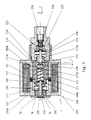
- Injection pump 1 One similar to the injection pump shown in FIG. 1 Injection pump 1 is shown in Fig. 5, the same Parts have the same reference numbers.
- the piston partially seated in the armature cylinder bore 217 205a is not fastened to the end wall 200d on the pressure line side, but axially movable and part of the spray valve device 3.
- the injection valve 3 has a valve cap 3b, which in the front wall 200d of the housing 200 in the injection valve side Interior 202 is screwed gripping.
- the valve cap has an injection nozzle hole in the center 3d.
- the piston 205a covers in its rest position with a Diameter reduced face 205b the injector bore 3a from.
- the reduced surface area 205b goes with it a truncated cone 205c in the cylindrical part of the piston 205a about.
- the piston 205a is in the armature cylinder bore 217 from a compression spring 240 against the injector bore 3d pressed, the compression spring 240 against another in the intermediate cylinder 241 arranged in the armature cylinder bore 217 is supported, which bore 217 in an injector side and into a tank-side area.
- the anchor cylinder in the tank-side area of the interior 202 Grooves on, the groove webs on the inner wall of the interior 202 and there are guides for the armature cylinder 210 form.
- the pressure surge is applied to the cone surface of the truncated cone 205c transfers and lifts the piston 205 against the pressure of the spring 240 from the nozzle 3a so that fuel is hosed.
- room 202a and a negative pressure in the tank-side interior 202 which also affects the Piston 205 acts, but is much less than the spring force the spring is 240, so that the piston is unaffected remains.
- the negative pressure opens the valve 229, so that Fuel is sucked up.
- the valve 229 closes due to the spring force of spring 228 again when the return movement the armature cylinder 210 begins, so that then by the armature-cylinder movement Fuel into the spaces of bore 217 and Interior 202 is pushed.
- the function of the valve 292 corresponds the function of the same valve 229 in the Embodiment of the injection pump 1 according to FIG. 13.
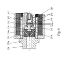
- FIG. 6 Another embodiment of the injection pump according to the invention 1, in which the injection nozzle 3 directly in the end wall 200d is housed in the housing 200 of the injection pump 1, results from Fig. 6. This embodiment is similar to that of Fig. 5, which is why the same parts with the same reference numerals Marked are.
- valve cap 3b forms a valve seat 3c for a tappet valve 244, the valve plate 245 against the outside the valve seat 3c is pulled, and its tappet stem 246 the the valve seat 3c following cap bore 3d free or through Ridges 247 reach radially supported and freely through the Armature cylinder bore 217 goes and just before the expanded area the bore 217 ends in which the tappet plate 218 des Tappet valve 218, 219 is added.
- This injection pump which has no separate piston, works in contrast to the embodiment according to FIG. 5 as follows. If the tappet valve 218, 219 from the valve seat of the armature cylinder 210 is taken, the sudden pressure build-up in the fuel takes place in space 202, 217 and 3d, so that the tappet valve 244 to Spraying against the pressure of the return spring 250 opens. Subsequently hits the plunger plate 218 after a further stroke "H" on plunger stem 246 and holds valve 244 open.
- FIG. 7 An embodiment similar to the embodiment shown in FIG. 6 the injection pump 1 according to the invention is shown in FIG. 7 shown, the same parts again with the same reference numerals are designated.
- the tappet stem 246 of the tappet valve 244 is made shorter and is sufficient in the rest position or starting position of the pump 1 only up to the injector-side end area of the armature cylinder bore 217. Accordingly, the return spring is 250 shortened. In addition, however, presses another Compression spring 251 from the tank side against the ring 248a one end against a central bore 217d Wall 217e supports the bore 217 in an injection valve side and divided a tank side area that communicate through hole 217d.
- the spring supports this version of injection pump 1 251 the opening of the valve 244 as in the case of the embodiment 6, in which the belching through the valve plate 218 is supported, which hits the pushrod 246.
- the Springs then also hold valve 244 in the open position, as long as the spring pressure of the spring 250 or 251 causes this.
Landscapes
- Engineering & Computer Science (AREA)
- Mechanical Engineering (AREA)
- General Engineering & Computer Science (AREA)
- Chemical & Material Sciences (AREA)
- Combustion & Propulsion (AREA)
- Fuel-Injection Apparatus (AREA)
- Electrical Control Of Air Or Fuel Supplied To Internal-Combustion Engine (AREA)
- Electromagnetic Pumps, Or The Like (AREA)
- Other Liquid Machine Or Engine Such As Wave Power Use (AREA)
- Steroid Compounds (AREA)
Description
- Fig. 1 und 2
- schematisch im Längsschnitt jeweils eine Ausführungsform der erfindungsgemäßen Einspritzvorrichtung,
- Fig. 3 und 4
- jeweils einen Schnitt durch eine Ankerdämpfungseinrichtung, und
- Fig. 5 bis 7
- schematisch im Längsschnitt jeweils eine Ausführungsform der erfindungsgemäßen Einspritzvorrichtung.
Claims (29)
- Kraftstoff-Einspritzvorrichtung, die nach dem Festkörper-Energiespeicher-Prinzip als Hubkolbenpumpe arbeitet, wobei ein in einem Hubkolbenzylinder angeordnetes Hubkolbenelement aus einer Ausgangsstellung während einer nahezu widerstandslosen Beschleunigungsphase, von einem Elektromagneten angetrieben, kinetische Energie speichert und ein Druckstoß durch ein die widerstandlose Beschleunigung plötzlich unterbrechendes Mittel erzeugt wird, so daß der Druckstoß auf den Kraftstoff übertragen wird, wobei der Druckstoß zum Abspritzen von Kraftstoff duch eine Einspritzdüseneinrichtung verwendet wird,
dadurch gekennzeichnet,
daß das die widerstandslose Beschleunigung unterbrechende Mittel ein in die Hubkolbenpumpe integriertes Anschlagventil mit einem sich im Hubkolbenzylinder abstützenden Ventilkörper (218, 219) und einem Ventilsitz (223) am Hubkolbemelement ist, das außerhalb des führenden flüssigkeitsdichten Kontaktbereichs zwischen dem Hubkolbenelement (210) und dem Hubkolbenzylinder der Hubkolbenpumpe angeordnet ist, und in der Ausgangsstellung des Hubkolbenelementes der Ventilkörper (218, 219) vom Ventilsitz (223) um einen bestimmten Spalt "X" beabstandet ist, so daß die widerstandslose Beschleunigungsphase unterbrochen wird, wenn das Ventil geschlossen wird, nachdem das Hubkolbenelement aus der Ausgangsstellung um die Länge des Spaltes "X" bewegt worden ist. - Kraftstoff-Einspritzvorrichtung nach Anspruch 1,
dadurch gekennzeichnet,
daß der Ventilsitz (223) am Hubkolbenelement (210) ausgebildet ist. - Kraftstoff-Einspritzvorrichtung nach Anspruch 1 und/oder 2,
dadurch gekennzeichnet,
daß der Ventilkörper ein Stößel, bestehend aus einem StöStößelteller (218) und einem Stößelstiel (219), ist. - Vorrichtung nach einem oder mehreren der Ansprüche 1 bis 3
dadurch gekennzeichnet,
daß das Hubkolbenelement als Pumpenzylinder (210) ausgebildet ist, wobei ein Gehäuseinnenraum (202) durch einen sich radial nach innen erstreckenden Ring (203) in einen tankseitigen und einen druckleitungsseitigen Innenraumbereich abgeteilt wird und wobei druckleitungsseitig gegen eine Ringkante des Rings (203) ein formschlüssig und fest in diesem Innenraum sitzender Ringwulst (204) eines Kolbens (205) der Hubkolbenpumpe (1) gesetzt ist, der die Ringöffnung (06) des Rings (203) mit Abstand durchgreift und in den tankseitigen Bereich des Innenraums (202) ragt, wo er in eine durchgehende Bohrung (217) des Ankerzylinders (210) eingreift. - Vorrichtung nach Anspruch 4,
dadurch gekennzeichnet,
daß der Kolben (205) von einer durchgehenden Bohrung (207) durchsetzt ist, die im tankseitigen Endbereich des Kolbens erweitert ausgebildet ist und dort ein Rückschlagventil (208) lagert, das von einer Schraubenfeder (209) in Richtung Tankseite für die Schließstellung gegen einen Ventilsitz (209a) gedrückt wird. - Vorrichtung nach Anspruch 4 und/oder 5,
dadurch gekennzeichnet,
daß auf dem im tankseitigen Innenraumbereich des Innenraums (202) befindlichen Teil des Kolbens (205) formschlüssig und gleitbar der Pumpenzylinder (210) der Hubkolbenpumpe sitzt, der von einer sich einendig auf dem Ring (203) und anderendig an einer Ringstufe (212) des Zylinders (210) abstützenden Schraubenfeder (211) mit seiner tankseitigen Stirnringfläche (214) gegen eine Ringstufe (213) im Innenraum (202) gedrückt wird, wobei ein die Stirnringfläche (214) überragender Ventilstutzen (215) mit radialem Abstand ein Stück in den in diesem Bereich radial verengten Innenraum (202) ragt und wobei die druckleitungsseitige Stirnringfläche des Zylinders (210) im Abstand vom Ring (203) angeordnet ist und somit ein Bewegungsraum für den Zylinder (210) geschaffen wird. - Vorrichtung nach Anspruch 6,
dadurch gekennzeichnet,
daß der formschlüssig an der Innenwandung des Innenraums (202) geführt sitzende Zylinder (2120) achsparallele stirnseitig offenen Längsnuten (216) in der Mantelfläche aufweist, und daß die den Pumpenzylinder (210) durchsetzende, durchgehende, den Kolben (205) aufnehmende Bohrung (217) tankseitig das dem Kolben (205) vorgeordnetes Stößelventil lagert, dessen Stößelteller (218) im Abstand von der Stirnringfläche des Kolbens (205) in einer kurzen Bohrungserweiterung angeordnet ist und dessen Stößelstil (219) die verengte Bohrung (217a) im Ventilstutzen (215) - sich gegen die Innenwandung der Bohrung (217a) abstützend - durchgreift und in den verengten Innenraum (202a) ragt. - Vorrichtung nach Anspruch 7,
dadurch gekennzeichnet,
daß am freien Ende des Stößelstiels (219) ein Teller (220) befestigt ist, der Löcher (221) aufweist, wobei der Stößelstiel (219) noch ein Stück über den Teller (220) hinausragt, und gegen die tankseitige Bodenfläche (222) des Innenraums (202a) stößt, wobei der Stößelstiel (219) so lang gewählt ist, daß der Stößelteller (218) von seinem Ventilsitz (223) der verengten Bohrung (217a) abgehoben ist, so daß ein bestimmter Spalt "X" gebildet wird. - Vorrichtung nach Anspruch 8 ,
dadurch gekennzeichnet,
daß eine Schraubenfeder (224) die Stellung des Stößelventils in der Ruhestellung der Hubkolbenpumpe stabilisiert, indem sich die Feder (224) einendig auf der Stirnringfläche (214) des Zylinders (210) und anderendig gegen den Teller (220) abstützt. - Vorrichtung nach einem oder mehreren der Ansprüche 4 bis 9,
dadurch gekennzeichnet,
daß von der Bodenfläche (222) sich achsparallele Bohrungen (225) in die Bodenwandung erstrecken und in einen axialen Ventilraum (226) münden, in dem ein von einer Schraubenfeder (228) in Tankrichtung gegen einen Ventilsitz (227) gedrückter Ventilteller (229) angeordnet ist, der peripher vom Ventilsitz (227) abdeckbare Rillen (230) aufweist, so daß das Ventil durch einen tankanschlußseitigen Druck gegen die Belastung der Feder (228) geöffnet werden kann und einen Durchgang vom Ventilraum (226) zu den Bohrungen (225) geschaffen wird. - Vorrichtung nach Anspruch 4,
dadurch gekennzeichnet,
daß der Kolben (205) einstückig mit der Stirnwandung (200d) des Gehäuses (200) ausgebildet ist, wobei das Standdruckventil (208, 209) druckleitungsseitig dem Kolben (205) in einem Rohrstutzen (208a) vorgeordnet ist und die druckleitungsseitige Mündung der durch den Kolben (205) gehenden Bohrung (207) abdeckt. - Vorrichtung nach Anspruch 11,
dadurch gekennzeichnet,
daß der Stößelstiel (219) relativ kurz ausgebildet ist und über die tankseitige Stirnringfläche (214) des Zylinders (210) nur um das Ventilspiel herausragen kann. - Vorrichtung nach Anspruch 12,
dadurch gekennzeichnet,
daß die Stirnringfläche (214) im Bereich der Stirnwandung (200c) gegen einen dort gelagerten Kunststoffblock (231) stößt, der Durchgangsbohrungen (232) aufweist, die peripher in Nuten (233) münden, die mit dem tankseitigen Innenraum (202) in Verbindung stehen, wobei vom tankseitigen Innenraum (202) Bohrungen (234) zum erweiterten Bohrungsbereich der Bohrung (217) im Zylinder (210) führen und wobei die Bohrungen (232) in den zum Tank führenden axialen Ventilraum (226) münden, der in einem Rohrstutzen (226a) untergebracht ist. - Vorrichtung nach Anspruch 13,
dadurch gekennzeichnet,
daß die Bohrungserweiterung der Bohrung (217) in der der Stößelteller (218) aufgenommen ist, druckleitungsseitig eine Ringstufe (235) bildet, die sich in der Ruhestellung des Stößelventils nur in geringem Abstand vor dem Stößelteller (218) befindet und gegen die der Stößelteller (218) stößt, wenn der Stößel trägheitsbedingt bei der Rückstellbewegung des Zylinders (210) vom Ventilsitz abhebt und/oder das Ventil vom Kunststoffblock (231) bei der Rückstellbewegung des Zylinders (210) rückgeprellt werden sollte. - Vorrichtung nach Anspruch 14,
dadurch gekennzeichnet,
daß in der Stirnfläche der Ringstufe (235) Ausnehmungen (235a) eingebracht sind, die einen ungehinderten Durchfluß des Kraftstoffs gewährleisten. - Vorrichtung nach einem oder mehreren der Ansprüche 13 bis 15,
dadurch gekennzeichnet,
daß die Stirnringfläche (214) mit geringem Abstand von der Oberfläche des Kunststoffblocks (231) angeordnet ist. - Vorrichtung nach Anspruch 16,
dadurch gekennzeichnet,
daß auf der Stirnringfläche (214) vorstehende Abstützstege (214a) angeordnet sind. - Vorrichtung nach einem oder mehreren der Ansprüche 4 bis 17,
gekennzeichnet, durch
eine Ankerdämpfungseinrichtung im freien Endbereich des Stößelstiels (219), wobei dort ein Flanschring (219a) angeordnet ist, der die Stirnringfläche (214) ein Stück seitlich übergreift und an der Stirnringfläche (214) anliegen kann, und wobei in der Oberfläche des Kunststoffblocks (231) eine dem Flanschring (219a) entsprechende Ausnehmung (231a) eingebracht ist, in die der Flanschring (219a) etwa formschlüssig paßt. - Vorrichtung nach Anspruch 18,
dadurch gekennzeichnet,
daß die Dicke des Flanschrings (219a) etwas größer als die Tiefe der Ausnehmung (231a) ausgeführt ist. - Vorrichtung nach einem oder mehreren der Ansprüche 4 bis 19,
dadurch gekennzeichnet,
daß in der druckleitungsseitigen Stirnwand (200d) eine Bohrung (234) angeordnet ist, die vom druckleitungsseitigen Innenraum (202) nach außen führt und auf die zweckmäßigerweise außenseitig ein Stutzen (237) mit einer Durchgangsbohrung (238) gesetzt ist, wobei durch die Bohrung (236) und den Ablaufstutzen (237) während der Startphase der Pumpe 1 bzw. des Motors oder laufend Kraftstoff vom Anker-Zylinder (210) abgepumpt werden kann. - Vorrichtung nach einem oder mehreren der Ansprüche 4 bis 20,
dadurch gekennzeichnet,
daß an der Innenwandung des druckleitungsseitigen Innenraums (202) eine sich an der Stirnwandung (200b) abstützende Druckfeder (238a) angeordnet ist, gegen die bei der Beschleunigung des Ankerzylinders (210) eine Stirnringfläche (239) des Ankerzylinders stößt und dabei die Feder komprimiert. - Vorrichtung nach einem oder mehreren der Ansprüche 4 bis 21,
dadurch gekennzeichnet,
daß der Zylinder (210) als kolbenartiges Ankerelement im Innenraum (202) flüssigkeitsdicht geführt wird. - Vorrichtung nach Anspruch 22,
dadurch gekennzeichnet,
daß ein teilweise in der Ankerzylinderbohrung (217) sitzender Kolben (205a) axial bewegbar gelagert ist und Teil der Abspritzventileinrichtung (3) ist. - Vorrichtung nach Anspruch 23,
dadurch gekennzeichnet,
daß die Abspritzventileinrichtung (3) eine Ventilkappe (3b) aufweist, die in die Stirnwand (200d) des Gehäuses (200) in den einspritzventilseitigen Innenraum (202) greifend eingeschraubt ist, der Kolben (205a) in seiner Ruhestellung mit einer im Durchmesser reduzierten Stirnfläche (205b) die Einspritzdüsenbohrung (3d) abdeckt und die im Durchmesser reduzierte Fläche (205b) mit einem Kegelstumpf (205c ) in den zylindrischen Teil des Kolbens (205a) übergeht. - Vorrichtung nach Anspruch 24,
dadurch gekennzeichnet,
daß der Kolben (205a) in der Ankerzylinderbohrung (217) von einer Druckfeder (240) gegen die Einspritzdüsenbohrung (3d) gedrückt wird, wobei sich die Druckfeder (240) anderendig gegen eine in der Ankerzylinderbohrung (217) angeordnete Zwischenwand (241) abstützt, die die Bohrung (217) in einen einspritzdüsenseitigen und in einen tankseitigen Bereich abteilt. - Vorrichtung nach Anspruch 25,
dadurch gekennzeichnet,
daß mindestens eine Bohrung (242) von der Stirnringfläche (212) durch den Ankerzylinder (210) in den erweiterten Zylinderbohrungsraum des tankseitigen Bereichs der Bohrung (217) führt, in dem der Stößelteller (218) aufgenommen ist, und daß eine Bohrung (243) durch den Ankerzylinder (210) vom einspritzdüsenseitigen Bereich der Bohrung (217) in den tankseitigen Innenraum (202) geht, wobei der mittlere Bereich des Anker-Zylinders (210) formschlüssig und nahezu flüssigkeitsdicht an der Innenwandung des Innenraums (202) sitzt. - Vorrichtung nach Anspruch 26,
dadurch gekennzeichnet,
daß der Anker-Zylinder (210) im tankseitigen Bereich des Innenraums (202) Nuten aufweist, wobei die Nutstege an der Innenwandung des Innenraums (202) anliegen und dort Führungen für den Anker-Zylinder (210) bilden. - Vorrichtung nach einem oder mehreren der Ansprüche 4 bis 22,
dadurch gekennzeichnet,
daß die Einspritzdüse (3) unmittelbar in der Stirnwand (200d) des Gehäuses (200) untergebracht ist und eine Ventilkappe (3b) mit einem Ventilsitz (3c) für ein Stößelventil (244) aufweist, dessen Ventilteller (245) von außen gegen den Ventilsitz (3c) gezogen wird und dessen Stößelstiel (246) die dem Ventilsitz (3c) nachfolgende Kappenbohrung (3d) frei oder durch Rippen (247) radial abgestützt durchgreift sowie frei durch die Ankerzylinderbohrung (217) geht und kurz vor dem erweiterten Bereich der Bohrung (217) endet, in dem der Stößelteller (218) des Stößelventils (218, 219)aufgenommen ist, wobei am freien Ende des Stößelstiels (246) ein Löcher oder radiale Ausnehmungen (248) aufweisender Ring (248a) befestigt ist, gegen den sich einspritzventilseitig eine Druckfeder (250) abstützt, die anderendig an der Stirnwand (200d) des Gehäuses (200) bzw. an der Ventilkappe (3b) anliegt, wobei der Ankerzylinder (210) lediglich die Durchgangsbohrung (217a) und keine radialen Nuten aufweist, sondern formschlüssig und flüssigkeitsdicht an der Innenwandung des Innenraums (202) anliegt und wobei der Stößelteller (218) nach einem bestimmten Hubweg auf den Stößelstiel (246) bei der Pumpbewegung stößt. - Vorrichtung nach Anspruch 28,
dadurch gekennzeichnet,
daß der Stößelstiel (246) des Stößelventils (244) kürzer ausgeführt ist und in der Ruhestellung der Pumpe (1) nur bis in den einspritzventilseitigen Endbereich der Anker-zylinderbohrung (217) reicht, wobei zusätzlich eine weitere Druckfeder (251) von der Tankseite her gegen den Ring (248a) drückt, die sich einendig gegen eine eine zentrale Bohrung (217d) aufweisende Wandung (217e) abstützt, die die Bohrung (217) in einen einspritzventilseitigen und einen tankseitigen Bereich unterteilt, die über die Bohrung (217d) in Verbindung stehen.
Applications Claiming Priority (3)
| Application Number | Priority Date | Filing Date | Title |
|---|---|---|---|
| DE4206817A DE4206817C2 (de) | 1991-10-07 | 1992-03-04 | Kraftstoff-Einspritzvorrichtung nach dem Festkörper-Energiespeicher-Prinzip für Brennkraftmaschinen |
| DE4206817 | 1992-03-04 | ||
| EP93905299A EP0629265B1 (de) | 1992-03-04 | 1993-03-04 | Kraftstoff-einspritzvorrichtung nach dem festkörper-energiespeicher-prinzip für brennkraftmaschinen |
Related Parent Applications (2)
| Application Number | Title | Priority Date | Filing Date |
|---|---|---|---|
| EP93905299.9 Division | 1993-03-04 | ||
| EP93905299A Division EP0629265B1 (de) | 1992-03-04 | 1993-03-04 | Kraftstoff-einspritzvorrichtung nach dem festkörper-energiespeicher-prinzip für brennkraftmaschinen |
Publications (3)
| Publication Number | Publication Date |
|---|---|
| EP0733798A2 EP0733798A2 (de) | 1996-09-25 |
| EP0733798A3 EP0733798A3 (de) | 1996-12-11 |
| EP0733798B1 true EP0733798B1 (de) | 2000-06-07 |
Family
ID=6453209
Family Applications (5)
| Application Number | Title | Priority Date | Filing Date |
|---|---|---|---|
| EP96101218A Expired - Lifetime EP0725215B1 (de) | 1992-03-04 | 1993-03-04 | Kraftstoff-Einspritzvorrichtung nach dem Festkörper-Energiespeicher-Prinzip für Brennkraftmaschinen |
| EP96109438A Expired - Lifetime EP0733798B1 (de) | 1992-03-04 | 1993-03-04 | Kraftstoff-Einspritzvorrichtung nach dem Festkörper-Energiespeicherprinzip für Brennkraftmaschinen |
| EP93905298A Expired - Lifetime EP0629264B1 (de) | 1992-03-04 | 1993-03-04 | Hubkolbenpumpe |
| EP93905299A Expired - Lifetime EP0629265B1 (de) | 1992-03-04 | 1993-03-04 | Kraftstoff-einspritzvorrichtung nach dem festkörper-energiespeicher-prinzip für brennkraftmaschinen |
| EP93905295A Expired - Lifetime EP0630442B1 (de) | 1992-03-04 | 1993-03-04 | Kraftstoff-einspritzvorrichtung nach dem festkörper-energiespeicher-prinzip für brennkraftmaschinen |
Family Applications Before (1)
| Application Number | Title | Priority Date | Filing Date |
|---|---|---|---|
| EP96101218A Expired - Lifetime EP0725215B1 (de) | 1992-03-04 | 1993-03-04 | Kraftstoff-Einspritzvorrichtung nach dem Festkörper-Energiespeicher-Prinzip für Brennkraftmaschinen |
Family Applications After (3)
| Application Number | Title | Priority Date | Filing Date |
|---|---|---|---|
| EP93905298A Expired - Lifetime EP0629264B1 (de) | 1992-03-04 | 1993-03-04 | Hubkolbenpumpe |
| EP93905299A Expired - Lifetime EP0629265B1 (de) | 1992-03-04 | 1993-03-04 | Kraftstoff-einspritzvorrichtung nach dem festkörper-energiespeicher-prinzip für brennkraftmaschinen |
| EP93905295A Expired - Lifetime EP0630442B1 (de) | 1992-03-04 | 1993-03-04 | Kraftstoff-einspritzvorrichtung nach dem festkörper-energiespeicher-prinzip für brennkraftmaschinen |
Country Status (8)
| Country | Link |
|---|---|
| US (3) | US5469828A (de) |
| EP (5) | EP0725215B1 (de) |
| JP (8) | JP2626678B2 (de) |
| AT (5) | ATE154100T1 (de) |
| AU (5) | AU671100B2 (de) |
| CA (3) | CA2127799C (de) |
| DE (5) | DE59308851D1 (de) |
| WO (3) | WO1993018296A1 (de) |
Families Citing this family (59)
| Publication number | Priority date | Publication date | Assignee | Title |
|---|---|---|---|---|
| US5469828A (en) * | 1992-03-04 | 1995-11-28 | Ficht Gmbh | Fuel injection device according to the solid-state energy storage principle for internal combustion engines |
| FR2713717B1 (fr) * | 1993-12-07 | 1996-01-26 | Rahban Thierry | Pompe à actionnement électromagnétique à collision élastique de l'équipage mobile. |
| DE4421145A1 (de) * | 1994-06-16 | 1995-12-21 | Ficht Gmbh | Ölbrenner |
| US5630401A (en) * | 1994-07-18 | 1997-05-20 | Outboard Marine Corporation | Combined fuel injection pump and nozzle |
| US5562428A (en) * | 1995-04-07 | 1996-10-08 | Outboard Marine Corporation | Fuel injection pump having an adjustable inlet poppet valve |
| ATE191064T1 (de) * | 1995-04-28 | 2000-04-15 | Ficht Gmbh & Co Kg | Kraftstoff-einspritzvorrichtung für brennkraftmaschinen |
| DE19515775C2 (de) * | 1995-04-28 | 1998-08-06 | Ficht Gmbh | Verfahren zum Ansteuern einer Erregerspule einer elektromagnetisch angetriebenen Hubkolbenpumpe |
| DE19515774C2 (de) * | 1995-04-28 | 1999-04-01 | Ficht Gmbh & Co Kg | Kraftstoff-Einspritzvorrichtung für Brennkraftmaschinen |
| DE19515782A1 (de) * | 1995-04-28 | 1996-10-31 | Ficht Gmbh | Kraftstoff-Einspritzvorrichtung für Brennkraftmaschinen |
| US5687050A (en) * | 1995-07-25 | 1997-11-11 | Ficht Gmbh | Electronic control circuit for an internal combustion engine |
| US5779454A (en) * | 1995-07-25 | 1998-07-14 | Ficht Gmbh & Co. Kg | Combined pressure surge fuel pump and nozzle assembly |
| DE19527550A1 (de) * | 1995-07-27 | 1997-01-30 | Ficht Gmbh | Verfahren zum Steuern des Zündzeitpunktes bei Brennkraftmaschinen |
| DE19541508A1 (de) * | 1995-11-08 | 1997-05-15 | Bosch Gmbh Robert | Kraftstoffeinspritzventil für Brennkraftmaschinen |
| FR2748783B1 (fr) * | 1996-05-17 | 1998-08-14 | Melchior Jean F | Dispositif d'injection de combustible liquide pour moteur a combustion interne |
| US6161525A (en) * | 1996-08-30 | 2000-12-19 | Ficht Gmbh & Co. Kg | Liquid gas engine |
| DE19643886C2 (de) * | 1996-10-30 | 2002-10-17 | Ficht Gmbh & Co Kg | Verfahren zum Betreiben einer Brennkraftmaschine |
| US6280867B1 (en) | 1997-12-05 | 2001-08-28 | Griff Consulting, Inc. | Apparatus for pumping a fluid in a fuel cell system |
| DE19845441C2 (de) | 1998-10-02 | 2003-01-16 | Ficht Gmbh & Co Kg | Verfahren zum elektronischen Trimmen einer Einspritzvorrichtung |
| DE19860573A1 (de) * | 1998-12-29 | 2000-07-06 | Eberspaecher J Gmbh & Co | Brennstoffdosierpumpe für ein Heizgerät, insbesondere für einen Zuheizer oder eine Standheizung eines Kraftfahrzeuges |
| DE19918984A1 (de) * | 1999-04-27 | 2000-11-02 | Deutz Ag | Kraftstoffversorgungssystem einer Brennkraftmaschine |
| US6283095B1 (en) * | 1999-12-16 | 2001-09-04 | Bombardier Motor Corporation Of America | Quick start fuel injection apparatus and method |
| DE10002721A1 (de) * | 2000-01-22 | 2001-08-02 | Bosch Gmbh Robert | Ventil zum Steuern von Flüssigkeiten |
| US6966760B1 (en) * | 2000-03-17 | 2005-11-22 | Brp Us Inc. | Reciprocating fluid pump employing reversing polarity motor |
| US6364281B1 (en) * | 2000-03-22 | 2002-04-02 | Eaton Corporation | Method of energizing solenoid operated valves |
| US6295972B1 (en) * | 2000-03-30 | 2001-10-02 | Bombardier Motor Corporation Of America | Fuel delivery using multiple fluid delivery assemblies per combustion chamber |
| US6792968B1 (en) * | 2000-05-30 | 2004-09-21 | Robert H. Breeden | Pump assembly and method |
| EP1306544B1 (de) * | 2000-08-02 | 2006-10-04 | Mikuni Corporation | Elektronisch gesteuerte kraftstoffeinspritzvorrichtung |
| JP4431268B2 (ja) * | 2000-11-17 | 2010-03-10 | 株式会社ミクニ | 電子制御燃料噴射装置 |
| CN1133810C (zh) * | 2001-02-16 | 2004-01-07 | 郗大光 | 电动燃油喷射装置 |
| JP2003003889A (ja) * | 2001-06-20 | 2003-01-08 | Denso Corp | 内燃機関の燃料供給装置 |
| DE60210508T2 (de) * | 2001-11-29 | 2007-05-10 | Mikuni Corp. | Verfahren zum antrieb einer kraftstoffeinspritzpumpe |
| US6693787B2 (en) * | 2002-03-14 | 2004-02-17 | Ford Global Technologies, Llc | Control algorithm for soft-landing in electromechanical actuators |
| US7753657B2 (en) * | 2005-02-02 | 2010-07-13 | Brp Us Inc. | Method of controlling a pumping assembly |
| DE102006003484A1 (de) * | 2005-03-16 | 2006-09-21 | Robert Bosch Gmbh | Vorrichtung zum Einspritzen von Kraftstoff |
| US20070075285A1 (en) * | 2005-10-05 | 2007-04-05 | Lovejoy Kim A | Linear electrical drive actuator apparatus with tandem fail safe hydraulic override for steam turbine valve position control |
| US7857281B2 (en) * | 2006-06-26 | 2010-12-28 | Incova Technologies, Inc. | Electrohydraulic valve control circuit with magnetic hysteresis compensation |
| DE102007037869A1 (de) * | 2007-08-10 | 2009-02-12 | Robert Bosch Gmbh | Aktuator für eine Brennkraftmaschine sowie Verfahren zum Betreiben eines Aktuators |
| DE102007039794A1 (de) | 2007-08-23 | 2009-03-12 | Eberspächer Unna GmbH & Co. KG | Dosiersystem und Verfahren zum Dosieren eines flüssigen Reduktionsmittels in ein Abgassystem einer Brennkraftmaschine |
| DE102008007349B4 (de) * | 2008-02-04 | 2021-07-08 | Robert Bosch Gmbh | Kompakte Einspritzvorrichtung mit reduzierter Dampfblasenneigung |
| DE102009012688B3 (de) * | 2009-03-11 | 2010-07-22 | Continental Automotive Gmbh | Ventil zum Einblasen von Gas |
| DE102009014444A1 (de) * | 2009-03-23 | 2010-10-07 | Continental Automotive Gmbh | Tankentlüftungsvorrichtung für eine aufgeladene Brennkraftmaschine und zugehöriges Steuerverfahren |
| DE102011077059A1 (de) * | 2011-06-07 | 2012-12-13 | Robert Bosch Gmbh | Kraftstoffeinspritzventil |
| DE102011078159A1 (de) * | 2011-06-28 | 2013-01-03 | Robert Bosch Gmbh | Kraftstoffeinspritzventil |
| US9500170B2 (en) | 2012-10-25 | 2016-11-22 | Picospray, Llc | Fuel injection system |
| US20170030298A1 (en) * | 2015-07-31 | 2017-02-02 | Briggs & Stratton Corporation | Atomizing fuel delivery system |
| JP6245238B2 (ja) * | 2015-09-11 | 2017-12-13 | トヨタ自動車株式会社 | 燃料ポンプ |
| DE102015014350B4 (de) * | 2015-11-05 | 2017-06-14 | L'orange Gmbh | Druckbetätigter Injektor |
| DE102015014349B4 (de) * | 2015-11-05 | 2017-06-14 | L'orange Gmbh | Druckstoßbetätigter Injektor |
| US10030961B2 (en) | 2015-11-27 | 2018-07-24 | General Electric Company | Gap measuring device |
| US10197025B2 (en) | 2016-05-12 | 2019-02-05 | Briggs & Stratton Corporation | Fuel delivery injector |
| WO2018022754A1 (en) | 2016-07-27 | 2018-02-01 | Picospray, Llc | Reciprocating pump injector |
| US10723610B2 (en) * | 2016-09-26 | 2020-07-28 | Gate Cfv Solutions, Inc. | Magnetically controlled valve using a blocking device and a movement device |
| US10947940B2 (en) | 2017-03-28 | 2021-03-16 | Briggs & Stratton, Llc | Fuel delivery system |
| DE102018200715A1 (de) * | 2018-01-17 | 2019-07-18 | Robert Bosch Gmbh | Kraftstofffördereinrichtung für kryogene Kraftstoffe |
| DE102018211338A1 (de) * | 2018-07-10 | 2020-01-16 | Robert Bosch Gmbh | Kraftstofffördereinrichtung für kryogene Kraftstoffe und Verfahren zum Betreiben einer Kraftstofffördereinrichtung |
| US11668270B2 (en) | 2018-10-12 | 2023-06-06 | Briggs & Stratton, Llc | Electronic fuel injection module |
| CN111441889B (zh) * | 2020-04-27 | 2024-11-05 | 安徽宝隽机车部件有限公司 | 一种燃油泵转子安装装置 |
| KR102572903B1 (ko) * | 2021-01-07 | 2023-08-30 | 주식회사 현대케피코 | 고압 연료펌프의 유량제어밸브 구조 |
| DE102021207320A1 (de) * | 2021-07-12 | 2023-01-12 | Robert Bosch Gesellschaft mit beschränkter Haftung | Sperrventil und Steuerungsverfahren zum Steuern eines Wasserstoffflusses aus einem Drucktank |
Family Cites Families (42)
| Publication number | Priority date | Publication date | Assignee | Title |
|---|---|---|---|---|
| DE213472C (de) * | ||||
| CH328209A (de) * | 1953-12-23 | 1958-02-28 | Cav Ltd | Brennstoffeinspritzpumpe für Brennkraftmaschinen |
| FR1150971A (fr) * | 1956-05-24 | 1958-01-22 | Perfectionnements apportés à des dispositifs d'injection de combustible | |
| US2881749A (en) * | 1956-11-13 | 1959-04-14 | Studebaker Packard Corp | Combination accumulator and starting pump for fuel injection system |
| FR1183662A (fr) * | 1957-10-01 | 1959-07-10 | Pompe d'injection électromagnétique pour moteurs à combustion interne | |
| DE1278792B (de) * | 1963-12-05 | 1968-09-26 | Vyzk Ustav Prislusenstvi Motor | Kraftstoffeinspritzpumpe mit Pumpen- und Verteilerrotor und Regelung der Einspritzmenge durch einen Ausweichkolben |
| DE2306875A1 (de) * | 1973-02-13 | 1974-08-15 | Bosch Gmbh Robert | Elektromagnetische dosierpumpe |
| DE2307435A1 (de) * | 1973-02-15 | 1974-08-22 | Bosch Gmbh Robert | Kraftstoffeinspritzeinrichtung fuer brennkraftmaschinen |
| JPS51120321A (en) * | 1975-04-14 | 1976-10-21 | Yanmar Diesel Engine Co Ltd | Fuel injection pump for diesel engine |
| DD120514A1 (de) * | 1975-06-09 | 1976-06-12 | ||
| CH597596A5 (de) * | 1975-06-27 | 1978-04-14 | Hoffmann La Roche | |
| GB1574128A (en) * | 1976-01-20 | 1980-09-03 | Lucas Industries Ltd | Fuel pump injector |
| GB1574132A (en) * | 1976-03-20 | 1980-09-03 | Lucas Industries Ltd | Fuel injection pumps |
| DE2634282C2 (de) * | 1976-07-28 | 1978-04-13 | Mannesmann Ag, 4000 Duesseldorf | Verfahren zum kontinuierlichen Einbringen von Zusatzmitteln in ein mit flüssigem Metall gefülltes Gefäß |
| DE2720144A1 (de) * | 1977-05-05 | 1978-11-16 | Volkswagenwerk Ag | Einspritzvorrichtung, insbesondere fuer eine brennkraftmaschine |
| DE2809122A1 (de) * | 1978-03-03 | 1979-09-06 | Bosch Gmbh Robert | Einspritzvorrichtung fuer eine brennkraftmaschine |
| NL7810629A (nl) * | 1978-10-25 | 1980-04-29 | Holec Nv | Inrichting voor het afgeven van brandstof aan een verbrandingsmotor. |
| US4355620A (en) * | 1979-02-08 | 1982-10-26 | Lucas Industries Limited | Fuel system for an internal combustion engine |
| JPS5749059A (en) * | 1980-09-08 | 1982-03-20 | Toshiba Corp | Driving circuit of injector |
| US4327695A (en) * | 1980-12-22 | 1982-05-04 | Ford Motor Company | Unit fuel injector assembly with feedback control |
| JPS5851233A (ja) * | 1981-09-21 | 1983-03-25 | Hitachi Ltd | 燃料噴射弁駆動回路 |
| DE3237258C1 (de) * | 1982-10-08 | 1983-12-22 | Daimler-Benz Ag, 7000 Stuttgart | Elektrisch vorgesteuerte Ventilanordnung |
| DD213472B5 (de) * | 1983-02-04 | 1999-12-30 | Ficht Gmbh | Pumpe-Duese-System fuer Brennkraftmaschinen |
| DE3329734A1 (de) * | 1983-08-17 | 1985-03-07 | Mannesmann Rexroth GmbH, 8770 Lohr | Proportionalmagnet |
| JPS6062658A (ja) * | 1983-09-16 | 1985-04-10 | Mitsubishi Heavy Ind Ltd | ジャ−ク式燃料ポンプの噴射開始タイミング変更装置 |
| GB8402470D0 (en) * | 1984-01-31 | 1984-03-07 | Lucas Ind Plc | Drive circuits |
| DE3567506D1 (en) * | 1984-08-14 | 1989-02-16 | Ail Corp | Fuel delivery control system |
| NL8501647A (nl) * | 1985-06-06 | 1987-01-02 | Volvo Car Bv | Brandstofinjector. |
| JPS61286540A (ja) * | 1985-06-14 | 1986-12-17 | Nippon Denso Co Ltd | 燃料噴射制御装置 |
| JPS62107265A (ja) * | 1985-11-02 | 1987-05-18 | Nippon Soken Inc | 電歪式油圧制御弁 |
| JP2546231B2 (ja) * | 1986-03-12 | 1996-10-23 | 日本電装株式会社 | 圧電素子の駆動装置 |
| FR2607278B1 (fr) * | 1986-11-26 | 1989-06-23 | Bendix Electronics Sa | Circuit integrable de regulation de courant dans une charge inductive et son application a la commande de bobine d'allumage d'un moteur a combustion interne |
| DE3701872A1 (de) * | 1987-01-23 | 1988-08-04 | Pierburg Gmbh | Elektromagnetisch getaktetes einspritzventil fuer gemischverdichtende brennkraftmaschinen |
| GB8703419D0 (en) * | 1987-02-13 | 1987-03-18 | Lucas Ind Plc | Fuel injection pump |
| EP0309753A1 (de) * | 1987-09-30 | 1989-04-05 | Siemens Aktiengesellschaft | Verfahren zur Überwachung einer induktiven Last |
| NZ222499A (en) * | 1987-11-10 | 1990-08-28 | Nz Government | Fuel injector pump: flow rate controlled by controlling relative phase of reciprocating piston pumps |
| JP2568603B2 (ja) * | 1988-01-11 | 1997-01-08 | 日産自動車株式会社 | 燃料噴射装置 |
| DE3903313A1 (de) * | 1989-02-04 | 1990-08-09 | Bosch Gmbh Robert | Speicherkraftstoffeinspritzvorrichtung |
| JPH03107568A (ja) * | 1989-09-22 | 1991-05-07 | Aisin Seiki Co Ltd | 燃料噴射装置 |
| DE4106015A1 (de) * | 1991-02-26 | 1992-08-27 | Ficht Gmbh | Druckstoss-kraftstoffeinspritzung fuer verbrennungsmotoren |
| US5469828A (en) * | 1992-03-04 | 1995-11-28 | Ficht Gmbh | Fuel injection device according to the solid-state energy storage principle for internal combustion engines |
| US5437255A (en) * | 1994-03-15 | 1995-08-01 | Sadley; Mark L. | Fuel injection sytem employing solid-state injectors for liquid fueled combustion engines |
-
1993
- 1993-03-04 US US08/295,811 patent/US5469828A/en not_active Expired - Lifetime
- 1993-03-04 WO PCT/EP1993/000491 patent/WO1993018296A1/de not_active Ceased
- 1993-03-04 AT AT93905299T patent/ATE154100T1/de not_active IP Right Cessation
- 1993-03-04 DE DE59308851T patent/DE59308851D1/de not_active Expired - Fee Related
- 1993-03-04 CA CA002127799A patent/CA2127799C/en not_active Expired - Fee Related
- 1993-03-04 AT AT93905298T patent/ATE140768T1/de not_active IP Right Cessation
- 1993-03-04 US US08/676,907 patent/US6188561B1/en not_active Expired - Lifetime
- 1993-03-04 EP EP96101218A patent/EP0725215B1/de not_active Expired - Lifetime
- 1993-03-04 JP JP5515324A patent/JP2626678B2/ja not_active Expired - Lifetime
- 1993-03-04 AU AU36308/93A patent/AU671100B2/en not_active Ceased
- 1993-03-04 JP JP5515321A patent/JP2626677B2/ja not_active Expired - Lifetime
- 1993-03-04 CA CA002127800A patent/CA2127800C/en not_active Expired - Fee Related
- 1993-03-04 AT AT96101218T patent/ATE169376T1/de not_active IP Right Cessation
- 1993-03-04 US US08/295,807 patent/US5520154A/en not_active Expired - Lifetime
- 1993-03-04 EP EP96109438A patent/EP0733798B1/de not_active Expired - Lifetime
- 1993-03-04 JP JP5515323A patent/JPH07504475A/ja active Pending
- 1993-03-04 WO PCT/EP1993/000495 patent/WO1993018297A1/de not_active Ceased
- 1993-03-04 CA CA002127801A patent/CA2127801C/en not_active Expired - Fee Related
- 1993-03-04 DE DE59304903T patent/DE59304903D1/de not_active Expired - Fee Related
- 1993-03-04 DE DE59303326T patent/DE59303326D1/de not_active Expired - Fee Related
- 1993-03-04 DE DE59310057T patent/DE59310057D1/de not_active Expired - Fee Related
- 1993-03-04 WO PCT/EP1993/000494 patent/WO1993018290A1/de not_active Ceased
- 1993-03-04 AT AT96109438T patent/ATE193753T1/de not_active IP Right Cessation
- 1993-03-04 EP EP93905298A patent/EP0629264B1/de not_active Expired - Lifetime
- 1993-03-04 AT AT93905295T patent/ATE146851T1/de not_active IP Right Cessation
- 1993-03-04 AU AU36305/93A patent/AU667345B2/en not_active Ceased
- 1993-03-04 EP EP93905299A patent/EP0629265B1/de not_active Expired - Lifetime
- 1993-03-04 EP EP93905295A patent/EP0630442B1/de not_active Expired - Lifetime
- 1993-03-04 AU AU36307/93A patent/AU664739B2/en not_active Ceased
- 1993-03-04 DE DE59306679T patent/DE59306679D1/de not_active Expired - Fee Related
-
1995
- 1995-11-16 AU AU37909/95A patent/AU679648B2/en not_active Ceased
-
1996
- 1996-07-02 AU AU56273/96A patent/AU681827B2/en not_active Ceased
- 1996-10-02 JP JP28149396A patent/JP3282711B2/ja not_active Expired - Fee Related
- 1996-10-02 JP JP8281492A patent/JP2867334B2/ja not_active Expired - Fee Related
-
1998
- 1998-07-13 JP JP21204598A patent/JP3330544B2/ja not_active Expired - Fee Related
- 1998-07-13 JP JP10212046A patent/JPH11107883A/ja active Pending
-
2001
- 2001-07-06 JP JP2001207051A patent/JP2002089413A/ja active Pending
Also Published As
Similar Documents
| Publication | Publication Date | Title |
|---|---|---|
| EP0733798B1 (de) | Kraftstoff-Einspritzvorrichtung nach dem Festkörper-Energiespeicherprinzip für Brennkraftmaschinen | |
| DE3874702T2 (de) | Steuerventil. | |
| DE60126173T2 (de) | Magnetventil und Brennstoffeinspritzventil unter Verwendung desselben | |
| EP0764254B1 (de) | Ölbrenner | |
| DE3151953C2 (de) | ||
| EP0941400A1 (de) | Ventil zum steuern von flüssigkeiten | |
| DE4206817C2 (de) | Kraftstoff-Einspritzvorrichtung nach dem Festkörper-Energiespeicher-Prinzip für Brennkraftmaschinen | |
| DE19545162B4 (de) | Brennstoffeinspritzvorrichtung mit federvorgespanntem Steuerventil | |
| WO1995034786A9 (de) | Ölbrenner | |
| EP0489740B1 (de) | Kraftstoffverteilereinspritzpumpe für brennkraftmaschinen | |
| EP0302904B1 (de) | Kraftstoffeinspritzpumpe für eine brennkraftmaschine | |
| EP0279267B1 (de) | Steuereinrichtung für ein Ventil | |
| DE2938412C2 (de) | ||
| DE2740879A1 (de) | Einspritzventil fuer hubkolbenbrennkraftmaschinen | |
| DE102009055356A1 (de) | Elektromagnetisch betätigtes Mengensteuerventil, insbesondere zur Steuerung der Fördermenge einer Kraftstoff-Hochdruckpumpe | |
| DE3731240C2 (de) | Einspritzvorrichtung | |
| EP0656472B1 (de) | Zur Vor- und Haupteinspritzung von Kraftstoff eingerichtete Einspritzvorrichtung | |
| WO2005052352A1 (de) | Einspritzdüse | |
| EP0685645A2 (de) | Einspritzventil für eine Kraftstoffeinspritzanlage einer Brennkraftmaschine, insbesondere eines Dieselmotors | |
| WO1984002379A1 (fr) | Gicleur de carburant pour moteurs a combustion interne | |
| WO2006079425A1 (de) | Kraftstoffeinspritzvorrichtung | |
| DE10329732A1 (de) | Kraftstoffeinspritzsystem für Brennkraftmaschinen | |
| DE3933233A1 (de) | Pumpeduese fuer die kraftstoffeinspritzanlage einer brennkraftmaschine | |
| DE4022198A1 (de) | Steuereinrichtung fuer eine kraftstoff-einspritzduese | |
| DE3933232A1 (de) | Pumpeduese fuer die einspritzanlage einer brennkraftmaschine |
Legal Events
| Date | Code | Title | Description |
|---|---|---|---|
| PUAI | Public reference made under article 153(3) epc to a published international application that has entered the european phase |
Free format text: ORIGINAL CODE: 0009012 |
|
| 17P | Request for examination filed |
Effective date: 19960612 |
|
| AC | Divisional application: reference to earlier application |
Ref document number: 629265 Country of ref document: EP |
|
| AK | Designated contracting states |
Kind code of ref document: A2 Designated state(s): AT BE DE FR GB IT SE |
|
| PUAL | Search report despatched |
Free format text: ORIGINAL CODE: 0009013 |
|
| AK | Designated contracting states |
Kind code of ref document: A3 Designated state(s): AT BE DE FR GB IT SE |
|
| 17Q | First examination report despatched |
Effective date: 19980512 |
|
| GRAG | Despatch of communication of intention to grant |
Free format text: ORIGINAL CODE: EPIDOS AGRA |
|
| GRAG | Despatch of communication of intention to grant |
Free format text: ORIGINAL CODE: EPIDOS AGRA |
|
| GRAH | Despatch of communication of intention to grant a patent |
Free format text: ORIGINAL CODE: EPIDOS IGRA |
|
| RAP1 | Party data changed (applicant data changed or rights of an application transferred) |
Owner name: FICHT GMBH & CO. KG |
|
| GRAH | Despatch of communication of intention to grant a patent |
Free format text: ORIGINAL CODE: EPIDOS IGRA |
|
| GRAA | (expected) grant |
Free format text: ORIGINAL CODE: 0009210 |
|
| AC | Divisional application: reference to earlier application |
Ref document number: 629265 Country of ref document: EP |
|
| AK | Designated contracting states |
Kind code of ref document: B1 Designated state(s): AT BE DE FR GB IT SE |
|
| REF | Corresponds to: |
Ref document number: 193753 Country of ref document: AT Date of ref document: 20000615 Kind code of ref document: T |
|
| GBT | Gb: translation of ep patent filed (gb section 77(6)(a)/1977) |
Effective date: 20000608 |
|
| REF | Corresponds to: |
Ref document number: 59310057 Country of ref document: DE Date of ref document: 20000713 |
|
| ET | Fr: translation filed | ||
| ITF | It: translation for a ep patent filed | ||
| PLBE | No opposition filed within time limit |
Free format text: ORIGINAL CODE: 0009261 |
|
| STAA | Information on the status of an ep patent application or granted ep patent |
Free format text: STATUS: NO OPPOSITION FILED WITHIN TIME LIMIT |
|
| 26N | No opposition filed | ||
| REG | Reference to a national code |
Ref country code: GB Ref legal event code: IF02 |
|
| PGFP | Annual fee paid to national office [announced via postgrant information from national office to epo] |
Ref country code: SE Payment date: 20020306 Year of fee payment: 10 |
|
| PGFP | Annual fee paid to national office [announced via postgrant information from national office to epo] |
Ref country code: AT Payment date: 20020313 Year of fee payment: 10 |
|
| PGFP | Annual fee paid to national office [announced via postgrant information from national office to epo] |
Ref country code: BE Payment date: 20020527 Year of fee payment: 10 |
|
| PGFP | Annual fee paid to national office [announced via postgrant information from national office to epo] |
Ref country code: GB Payment date: 20030226 Year of fee payment: 11 |
|
| PG25 | Lapsed in a contracting state [announced via postgrant information from national office to epo] |
Ref country code: AT Free format text: LAPSE BECAUSE OF NON-PAYMENT OF DUE FEES Effective date: 20030304 |
|
| PG25 | Lapsed in a contracting state [announced via postgrant information from national office to epo] |
Ref country code: SE Free format text: LAPSE BECAUSE OF NON-PAYMENT OF DUE FEES Effective date: 20030305 |
|
| PGFP | Annual fee paid to national office [announced via postgrant information from national office to epo] |
Ref country code: FR Payment date: 20030310 Year of fee payment: 11 |
|
| PGFP | Annual fee paid to national office [announced via postgrant information from national office to epo] |
Ref country code: DE Payment date: 20030313 Year of fee payment: 11 |
|
| PG25 | Lapsed in a contracting state [announced via postgrant information from national office to epo] |
Ref country code: BE Free format text: LAPSE BECAUSE OF NON-PAYMENT OF DUE FEES Effective date: 20030331 |
|
| REG | Reference to a national code |
Ref country code: FR Ref legal event code: TP Ref country code: FR Ref legal event code: CD |
|
| BERE | Be: lapsed |
Owner name: *FICHT G.M.B.H. & CO. K.G. Effective date: 20030331 |
|
| EUG | Se: european patent has lapsed | ||
| PG25 | Lapsed in a contracting state [announced via postgrant information from national office to epo] |
Ref country code: GB Free format text: LAPSE BECAUSE OF NON-PAYMENT OF DUE FEES Effective date: 20040304 |
|
| PG25 | Lapsed in a contracting state [announced via postgrant information from national office to epo] |
Ref country code: DE Free format text: LAPSE BECAUSE OF NON-PAYMENT OF DUE FEES Effective date: 20041001 |
|
| GBPC | Gb: european patent ceased through non-payment of renewal fee | ||
| PG25 | Lapsed in a contracting state [announced via postgrant information from national office to epo] |
Ref country code: FR Free format text: LAPSE BECAUSE OF NON-PAYMENT OF DUE FEES Effective date: 20041130 |
|
| REG | Reference to a national code |
Ref country code: FR Ref legal event code: ST |
|
| PG25 | Lapsed in a contracting state [announced via postgrant information from national office to epo] |
Ref country code: IT Free format text: LAPSE BECAUSE OF NON-PAYMENT OF DUE FEES Effective date: 20050304 |