EP0696018B1 - Anzeigeverfahren für einen gemeinsamen virtuellen Raum und Vorrichtung unter Verwendung dieses Verfahrens - Google Patents
Anzeigeverfahren für einen gemeinsamen virtuellen Raum und Vorrichtung unter Verwendung dieses Verfahrens Download PDFInfo
- Publication number
- EP0696018B1 EP0696018B1 EP95112163A EP95112163A EP0696018B1 EP 0696018 B1 EP0696018 B1 EP 0696018B1 EP 95112163 A EP95112163 A EP 95112163A EP 95112163 A EP95112163 A EP 95112163A EP 0696018 B1 EP0696018 B1 EP 0696018B1
- Authority
- EP
- European Patent Office
- Prior art keywords
- avatar
- terminal
- video
- user
- position information
- Prior art date
- Legal status (The legal status is an assumption and is not a legal conclusion. Google has not performed a legal analysis and makes no representation as to the accuracy of the status listed.)
- Expired - Lifetime
Links
Images


Classifications
-
- G—PHYSICS
- G06—COMPUTING; CALCULATING OR COUNTING
- G06T—IMAGE DATA PROCESSING OR GENERATION, IN GENERAL
- G06T15/00—3D [Three Dimensional] image rendering
- G06T15/10—Geometric effects
- G06T15/30—Clipping
-
- G—PHYSICS
- G06—COMPUTING; CALCULATING OR COUNTING
- G06T—IMAGE DATA PROCESSING OR GENERATION, IN GENERAL
- G06T17/00—Three dimensional [3D] modelling, e.g. data description of 3D objects
-
- H—ELECTRICITY
- H04—ELECTRIC COMMUNICATION TECHNIQUE
- H04N—PICTORIAL COMMUNICATION, e.g. TELEVISION
- H04N7/00—Television systems
- H04N7/14—Systems for two-way working
- H04N7/141—Systems for two-way working between two video terminals, e.g. videophone
- H04N7/148—Interfacing a video terminal to a particular transmission medium, e.g. ISDN
-
- H—ELECTRICITY
- H04—ELECTRIC COMMUNICATION TECHNIQUE
- H04N—PICTORIAL COMMUNICATION, e.g. TELEVISION
- H04N7/00—Television systems
- H04N7/14—Systems for two-way working
- H04N7/15—Conference systems
-
- G—PHYSICS
- G06—COMPUTING; CALCULATING OR COUNTING
- G06T—IMAGE DATA PROCESSING OR GENERATION, IN GENERAL
- G06T2200/00—Indexing scheme for image data processing or generation, in general
- G06T2200/16—Indexing scheme for image data processing or generation, in general involving adaptation to the client's capabilities
-
- H—ELECTRICITY
- H04—ELECTRIC COMMUNICATION TECHNIQUE
- H04N—PICTORIAL COMMUNICATION, e.g. TELEVISION
- H04N7/00—Television systems
- H04N7/14—Systems for two-way working
- H04N7/15—Conference systems
- H04N7/157—Conference systems defining a virtual conference space and using avatars or agents
Definitions
- the present invention relates to a virtual space display method which allows user terminals connected to a communication network to freely move their avatars to desired positions in a shared virtual space and causes the user terminals to display images in their fields of vision in the virtual space.
- the invention also pertains to a virtual space sharing apparatus using the above-mentioned virtual space display method.
- the virtual space is displayed as a user interface of a specific application such as a combat simulation, electronic mail system or electronic conference system.
- Users are allowed to move their avatars in the virtual space, but since video images that the users observe on their terminal displays are video images captured by their avatars in the virtual space that is observed from the outside thereof, the virtual space has a defect that the users cannot fully feel a sense of real existence in the space.
- the user avatars meet and talk with each other in the virtual space, their voices are merely transmitted and received between them; hence, also from the auditory point of view, the users cannot feel totally immersed in the virtual space.
- the virtual space lacks a sense of real existence or reality since the avatars of the users are all displayed in the same size.
- a virtual space sharing apparatus comprising a plurality of terminals connected to a network, means for sending and receiving video image data of users obtained by a TV camera, video processing means for generating avatars on the basis of the video image data.
- the avatars are in fact synthetic 3D models of the participants to the system constructed by a wire frame model mapped by color texture.
- tape marks are attached to facial muscles and the marks are visually tracked by the TV camera. The results of the tracking represent the sent video image data that are used to move the nodes of the wire frame model of the face.
- each user terminal uses the relationship between position information of its avatar and that of the other avatars to determine the image quality of the latter, then requests the other terminals or a server for video images of the other avatars, each having the thus determined quality, and the other terminals or server sends the requested images of the avatars to the requesting terminal after converting them into video images of the specified quality.
- a plurality of terminals connected via a communication network share a virtual space and are allowed to freely move avatars of terminal users in the virtual space and display on their terminal displays the scenes that the avatars are observing in the virtual space.
- Images representing the avatars of the users (which may be symbols, illustrations of the users or illustrations with users' facial video images embedded therein and which will hereinafter be referred to simply as avatar images) are formed at the positions of the avatars in the virtual space. Accordingly, the scene in the virtual space that is displayed on a display unit of each user terminal contains avatar images of other users in the field of vision of the avatar of each user in the virtual space.
- the virtual space display system of the present invention can also be designed so that the users receive predetermined services such as various entertainments, shopping and various pieces of information, but the system of the present invention is configured, in particular, to allow the avatar of each user to talk with other avatars whom it happens to meet in the virtual space.
- the system of the present invention can be designed as either of a distributed connection type system and a centralized one.
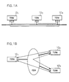
- a distributed connection type system as shown in Fig. 1A, a plurality of terminals 10 1 , 10 2 and 10 3 connected to the thick-lined communication network such as LAN (local area network) are each adapted to form a common virtual space and to send and receive data to and from the other terminals as indicated by the thin-lined arrows.
- Each terminal sends data representing the position of the avatar of the user in the virtual space and data representing the direction of eyes of the avatar (hereinafter referred to as position information) to all the other terminals at regular time intervals or when the position or direction data changes.
- position information data representing the position of the avatar of the user in the virtual space and data representing the direction of eyes of the avatar
- each terminal Upon receiving the position data and direction-of-eye data from other terminals, each terminal checks the data to see if the avatars of the other terminal users exist in the visual field of its avatar, and if so, the terminal displays the avatar images of the other terminal users at the positions specified by the position data received. Moreover, as explained with reference to an example described later on, each user sends his voice or speech from his terminal to all the other terminals, and as described later in respect of an embodiment of the invention, if necessary, the user sends, for example, his facial video to other terminals by request.
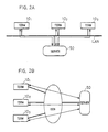
- the terminals 10 1 , 10 2 and 10 3 are all connected to a server 50 via a communication network such as LAN and perform two-way communication with the server 50 as indicated by the thin-lined arrows.
- each terminal sends at least the position information of the avatar of its user to the server 50; the server 50 performs required processing on the basis of the position information received from each terminal and sends the processed position information to all the terminals 10 1 , 10 2 and 10 3 .
- Fig. 2B shows the case where the terminals 10 1 , 10 2 and 10 3 are all connected to the server 50, for example, via ISDN.
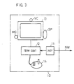
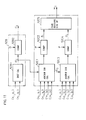
- Fig. 3 schematically illustrates an example of the configuration of each terminal unit 10 which forms the virtual space sharing apparatus for use in the centralized connection type system.
- the terminal unit 10 has a channel interface part 11 connected to a network (LAN, ISDN or the like), a terminal control device 12, a display 13, a control device 14, a speaker SP, a microphone MC and a video camera VC.
- a network LAN, ISDN or the like
- a terminal control device 12 a display 13, a control device 14, a speaker SP, a microphone MC and a video camera VC.
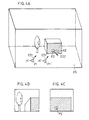
- Fig. 4A schematically illustrates the architecture of a virtual space VS provided beforehand for the terminal control device 12 of the terminal unit 10 1 of a user U1, positions P1 and P2 (given as coordinate values) of avatars A1 and A2 of users in the virtual space VS and the directions of eyes (indicated by the arrows ED1 and ED2) of the avatars A1 and A2.
- position P1' indicates the position of the avatar A1 having moved thereto and the direction of eye at the position P1' is indicated by the arrow ED1'.
- Fig. 4A schematically illustrates the architecture of a virtual space VS provided beforehand for the terminal control device 12 of the terminal unit 10 1 of a user U1, positions P1 and P2 (given as coordinate values) of avatars A1 and A2 of users in the virtual space VS and the directions of eyes (indicated by the arrows ED1 and ED2) of the avatars A1 and A2.
- position P1' indicates the position of the avatar A1 having moved thereto
- FIG. 4B shows a visual field image that the avatar A1 observes in the direction ED1 from the position P1; this visual field image is displayed on the display 13 of the terminal unit 10 1 of the user U1.
- Fig. 4C shows a visual field image that the avatar A1 in Fig. 4A observes at the position P1' after having moved thereto, the direction of its eyes being indicated by the arrow ED1'.
- the terminal control device 12 responds to the "move" instruction to display on the display 13 the visual field image in the virtual space VS viewed from the new position P1' (Fig. 4C) in place of the visual field image from the position P1 displayed until then (Fig. 4B), and the control device 12 sends the new position P1' from the interface 11 to the server 50 via the communication network NW.
- the avatar image A1 representing the user U1 in the virtual space VS is not displayed on the display 13 of the terminal 10 1 of his own.
- the avatar image A2 of the other user U2 is displayed in the visual field image viewed from the viewing point P1' (Fig. 4C).
- the server 50 has, as shown in Fig. 5, a channel interface part 51, a connection control part 52 and a table memory 53.
- the channel interface part 51 is connected via the communication network NW to the terminal units 10 1 and 10 2 , receives therefrom the position information of their avatars, that is, the viewing points P1 and P2 and directions of eyes ED1 and ED2 of the avatars A1 and A2, transmits the position information to all terminals except the transmitting one and controls audio and video channel connection between the terminals specified by the connection control part 52.
- the connection control part 52 writes the received position information, that is, the coordinates of the positions (The virtual space is three-dimensional and the position of each avatar is expressed by three-dimensional coordinates but will hereinafter be expressed by two-dimensional coordinates.) (x, y) and the directions of eyes ED in a position information table 53A of the table memory 53 in correspondence with the respective terminals.
- the terminals corresponding to the two avatars are connected via the channel interface part 51 to enable communication or conversation between the users of these terminals.
- the conversation enable condition consists of, for example, the distance between the avatars and the degree of eye-to-eye contact between them as described later with reference to other examples.
- the channel interface part 51 relays processed audio and video data between the terminals 10 1 and 10 2 , that is, sends the data received from the terminal 10 1 to the terminal 10 2 and the data received from the latter to the former.
- the terminal control part 12 of the terminal 10 1 decodes the audio data received from the terminal 10 2 via the channel interface part 51 and outputs the sound from the speaker SP, creates the avatar image at the position specified by the coordinate value (x 2 , y 2 ) contained in the position information received from the terminal 10 2 and outputs it to the display 13 in combination with the visual field image in the virtual space being currently displayed. Similarly, the terminal 10 2 processes and outputs the audio and video data received from the terminal 10 1 .
- the position information from the terminal is sent as part of a "move" message MM of such a format as shown in Fig. 6.
- the "move" message MM is composed of an avatar identifier AID, a message identifier MID, a space identifier SID, a coordinate value COV, the direction of eyes ED and a state flag SFLG.
- the avatar identifier AID is a pre-assigned unique number representing the terminal having sent the message.
- the message identifier MID is a predetermined number representing the message for sending position information based on the movement of the avatar.
- the coordinate value COV and the direction of eyes ED are a position coordinate value (x, y, z) and a direction-of-eyes value ⁇ (vector) of the avatar in the virtual space, respectively.
- the state flag SFLG is a value indicating the state of the avatar (moving, communicating, selecting, or idle).
- the "selecting" state is used in a message for receiving a service, and a button value for selecting an item from a service menu by the control device 14 is used as the flag.
- the button value is a value indicating which button of an input device (a mouse or joystick) is being pressed.
- the "idle” indicates the state in which the user is not using the terminal.
- Fig. 7 illustrates in block form the configuration of the terminal control part 12 in each terminal unit 10 of Fig. 3 in a centralized connection type system.
- the terminal control part 12 comprises: a video image generating part 12G which generates a CG visual field image viewed in the specified direction of eyes from the specified coordinate position in the three-dimensional virtual space, for display on the display 13; a control input processing part 12D which receives the input from the control device 14 and processes it for conversion to the coordinate value and the button value; a communication interface 12A which performs processing for transmission and reception to and from the communication network NW; a file unit 12F which stores display data, virtual space image data, software and user data; a management table memory 12E; an audio output processing part 12J which receives audio data and provides an analog speech signal to the microphone MC; an audio/video input part 12K which performs digital processing of input speech from the microphone MC and a video signal from the video camera VC and provides them to the server 50; and a CPU 12C which controls the operation of the terminal control part
- the management table memory 12E there are stored the position coordinate COV and direction of eyes ⁇ of the user's avatar inputted from the control input processing part 12D through the manipulation of the control device 14, the position coordinates COV and direction of eyes ⁇ of other avatars, change flags CFLG and state flags SFLG received from the server 50 (or other terminals); these pieces of information are stored in correspondence with the respective avatar identifiers AID.
- the avatar identifier AID, the state flag SFLG, the coordinate value COV and the direction of eyes ED are the same as those used in the "move" message depicted in Fig. 6.
- the CPU 12C reads out of the management table memory 12E the position (x,y,z) and direction of eyes ⁇ 1 corresponding to the identifier AID 1 of the avatar A1 of the user U1, instructs the video image generating part 12G to generate the visual field image observed in the direction of eyes ⁇ 1 from the position (x,y,z) in the virtual space stored as data in the file unit 12F, detects other avatars present in that field of vision from their coordinate values stored in the table memory 12E, generates avatar images at the positions of the detected avatars and instructs the display 13 to display thereon the avatar images in combination with the visual field image.
- the avatar images that are displayed on the display 13 are, for example, video images of users' faces received from the server 50 and produced in sizes corresponding to the distances from the avatar A1 of the user U1 to
- CFLG change flag
- each terminal sends to all the other terminals the "move" message MM of the format of Fig. 6 which contains the position information on the avatar of said each terminal and, at the same time, writes the message into the management table memory 12E of the terminal control part 12 shown in Fig. 7.
- each terminal writes into the management table memory 12E the "move" messages MM of the same format received from the other terminals and, at the same time, forms and displays other avatar images, which are observed in the field of vision from the position of its user's avatar, at their specified positions in the visual field image.
- the terminal control part 12 of each terminal needs only to incorporate therein between the communication interface 12A and the bus 12B a part that corresponds to the channel interface part 51 of the server 50 in the centralized connection type system shown in Fig. 5.
- the functions of the connection control part 52 and the table memory 53 in Fig. 5 can be implemented by the CPU 12 and the management table memory 53 in Fig. 7, respectively.
- Fig. 10 illustrates an example of the server of the virtual space sharing apparatus for use in the centralized connection type system which performs the processing (f). This example is shown to have three terminals. For the sake of brevity, no video-related parts are shown.
- the server 50 swaps speech data and position information with the terminals via channels CH 1 , CH 2 and CH 3 .
- the data received via the channels CH 1 , CH 2 and CH 3 are received in channel interface parts INF 1 , INF 2 and INF 3 , respectively.
- the channel interface parts INF 1 to INF 3 analyze the received data and, in the case of speech data, transfer it to a speech switching part 52S.
- the channel interface parts INF 1 to INF 3 write the position data and the direction-of-eyes data in the table memory 53 and, at the same time, transfer them to a position information distributing part 52A.
- the position information distributing part 52A copies the position information received from the channel interface part INF 1 and transfers it to the channel interface parts INF 2 and INF 3 and copies the position information received from the channel interface part INF 2 and transfers it to the channel interface parts INF 1 and INF 3 . Furthermore, the position information distributing part 52A copies the position information and direction-of-eyes information received from the channel interface part INF 3 and transfers them to the channel interface parts INF 1 and INF 2 .
- a distance decision part 52B reads out the position information from the table memory 53 and calculates all distances d ij (i,j:1,2,3, i ⁇ j) between avatars A i and A j .
- the distance decision part 52B compares each distance d ij with a predetermined threshold value D and sets the distance d ij to a value 1 or 0, depending on whether 0 ⁇ d ij ⁇ D or d ij >0, and transfers the value to a mixing object determining part 52D.
- An eye contact decision part 52C uses the position data and the direction-of-eyes data to calculate a value w ij which indicates whether either of avatars are in the field of vision of the other.
- the eye contact decision part 52C sets the value w ij to "1" or "0,” depending on whether or not the viewing points (the positions of avatars) of two users Ui and Uj are each in the field of vision of the other, and transfers the value w ij to the mixing object determining part 52D.
- the distance decision part 52B comprises a distance calculating part 52B1 for calculating the distance between two avatars and a comparison part 52B2 for making a check to see if the calculated distance is within the threshold value D.
- the eye contact deciding part 52C comprises direction-of-avatar calculating parts 52C1 and 52C3 each of which calculates the direction of one of two avatars from the other, comparison parts 52C2 and 52C4 which compare calculated directions ⁇ i and ⁇ j with a predetermined visual-field threshold value ⁇ to determine if either of the avatars are in the field of vision of the other, and a coincidence deciding logical operation part52C5 which uses the two results of comparison to determine if the two avatars establish eye-to-eye contact.
- a coordinate axis is set in the virtual space VS; let the coordinates of the position P i of the avatar A i be (x i , y i ) and the coordinates of the position P j of the avatar A j be (x j , y j ). Furthermore, let the direction-of-eyes vector i of the avatar A i be (i x ,i y ) and the direction-of-eyes vector j of the avatar A j be (j x ,j y ). Incidentally, the direction-of-eyes vector is a unit vector.
- the distance between the avatars A i and A j can be calculated by the following equation on the basis of the position coordinates (x i ,y i ) and (x j ,y j ) inputted into the distance calculating part 52B1.
- d ij ⁇ (x j -x i ) 2 + (y j -y i ) 2 ⁇ 1 ⁇ 2
- the distance d ij is compared with the predetermined threshold value D, and as referred to previously, the distance d ij is set to a value "1" or "0,” depending on whether O ⁇ d ij ⁇ D or d ij >D.
- the distance value d ij thus set is transferred to the mixing object determining part 52D.
- the coincidence deciding logical operation part 52C5 calculates a value w which indicates whether the fields of vision of users coincide with each other, on the basis of the position coordinates (x i ,y i ) and (x j ,y j ) and the direction-of-eyes vectors (i x ,i y ) and (j x ,j y ) inputted into the direction-of-avatar calculating parts 52C1 and 52C3.
- cos ⁇ i can be determined by calculating the inner product of the vector i and the vector P ij from the coordinate P i to P j .
- i ⁇ P ij
- cos ⁇ i i x (x j -x i )+i y (y j -y i ) where
- is a unit vector 1 and
- This calculation can also be conducted using the distance d ij calculated in the distance calculating part 52B1.
- the direction ⁇ i thus calculated by the direction-of-avatar calculating part 52C1 is compared with the predetermined visual-field threshold value ⁇ in the comparison part 52C2, and it is set to a value "1" or "0,” depending on whether 0 ⁇ i ⁇ or ⁇ i .
- the thus set value ⁇ i is inputted into the coincidence deciding logical operation part 52C5.
- the direction ⁇ j thus calculated in the calculating part 52C3 is compared with the predetermined visual-field threshold value ⁇ , and it is set to a value "1" or "0,” depending on whether 0 ⁇ j ⁇ or ⁇ j .
- Fig. 12 shows that the avatar A j is in the field of vision ⁇ of the avatar A i , whereas the avatar A i is out of the field of vision ⁇ of the avatar A j and hence is not recognized.
- a preferable value of the visual angle ⁇ is 45 degrees, for instance.
- the output w ij from the logical operation part 52C5 is transferred to the mixing object determining part 52D.
- those voices which satisfy a condition p 12 1 that is, those voices which are to be connected to the channel CH 3 accommodated in the channel interface part INF 3 , are selected and mixed by a mixer 52M 3 , thereafter being transferred to the channel interface part INF 3 .
- the channel interface parts INF 1 , INF 2 and INF 3 provide on the channels CH 1 , CH 2 and CH 3 the position information containing the position data and the direction-of-eyes data, received from the position information distributing part 52, and the speech data received from the mixers 52M 1 , 52M 2 and 52M 3 .
- the eye contact deciding part 52C in Fig. 10 need not be provided and the mixing object determining part 52D controls the switch 52S on the basis of the distance d ij alone.
- the users of the avatars A6 and A7 could hear voices of the both groups as environment sounds, they would feel the existence of the other avatars in the virtual space VS like in the real world.
- the users of the avatars A1 and A2 engaged in conversation could also experience of enhanced realism of the virtual space VS if they could hear, as environment sounds, the voices of the avatars A3 to A5 and sounds made by the avatars A6 and A7.
- Fig. 14 shows how the speech path switch 52S and the mixer 52M in the server 50 of the apparatus of this example are interconnected in the case of Fig. 13.
- the terminals 10 1 to 10 7 of the seven users are present in the same virtual space and that the group of two users corresponding to the terminals 10 1 and 10 2 and the group of three users corresponding to the terminals 10 3 , 10 4 and 10 5 are engaged in conversation independently of each other.
- the mixer 52M is adaptively divided into mixing parts 52M A and 52M B corresponding to the two conversation groups, respectively, and a mixing part 52M C for all the avatars in the virtual space VS.
- the switch 52S has a construction which one-way connects sounds and voices received from all the terminals 10 1 to 10 7 to the mixing part 52M C .
- a sound S C produced by mixing the sounds and speech data D1 to D7 thus one-way transmitted from all the terminals 10 1 to 10 7 , is attenuated by a loss inserting part 5L C down to a level appropriate for an environment sound and transmitted to the terminals 10 6 and 10 7 of the users who are not engaged in conversation. In this way, the users of the terminals 10 6 and 10 7 can hear, as environment sounds, the sounds made and voices uttered by all the users present in the shared virtual space.
- the switch 52S two-way connects the speech data SD 1 and SD 2 sent from the terminals 10 1 and 10 2 to the mixing part 52M A and, at the same time, it one-way connects the mixed sound S C , inputted from the mixing part 52M C via the loss inserting part 5L C , to a loss inserting part 5L A to attenuate to such a sound pressure level as not to hinder conversation, after which the mixed sound S C is provided to the mixing part 52M A .
- the mixing part 52M A mixes the speech data SD 2 from the terminal 10 2 and the environment sound S C and sends the mixed sound to the terminal 10 1 via the switch 52S; furthermore, the mixing part 52M A mixes the speech data SD 1 from the terminal 10 1 and the environment sound S C and sends the mixed sound to the terminal 10 2 via the switch 52S.
- the users of the terminals 10 1 and 10 2 are capable of hearing the environment sound S C of the reduced sound pressure level while at the same time carrying on a two-way conversation as in the case of talking to each other over the telephone.
- the output from the mixing part 52M C is similarly connected to the mixing part 52M B via the loss inserting parts 5L C and 5L B , and the mixing part 52M B generates speech data to be sent to each terminal by mixing speech data from all the other terminals and the environment sound S C and sends it to the terminals via the switch 52S, enabling the users of the terminals to hear the environment sound S C of the lowered sound pressure level while carrying on two-way conversation.
- Fig. 15 the server 50, which is provided with the switch 52S and the mixer 52M shown in Fig. 14, will be further described.
- the number of terminals is three and that the users of the terminals 10 1 and 10 2 are talking with each other, leaving the user of the terminal 10 3 alone.
- the interface INF and the switch 52S are two-way connected, but in Fig. 15 the channel interface parts INF 1 to INF 3 and the switch 52S are shown to be one-way connected with a view to showing the kinds of speech data that are transmitted and received between them.
- Fig. 15 the channel interface parts INF 1 to INF 3 and the switch 52S are shown to be one-way connected with a view to showing the kinds of speech data that are transmitted and received between them.
- the virtual space and respective terminals transmit audio data and position information data via an advanced information system INS network and the channels CH 1 to CH 3 in the server 50.
- pieces of data received via the channels CH 1 to CH 3 are received in the channel interface parts INF 1 to INF 3 , respectively.
- the channel interface part INF 1 analyzes the received data and, if it is speech data SD 1 , transfers it to the switch 52S.
- the channel interface parts INF 2 and INF 3 analyze the received data and, if they are speech data SD 2 and SD 3 , transfer them to the switch 52S.
- the channel interface parts INF 1 to INF 3 transfer these pieces of data to the position information distributing part 52A and write them into the table memory 53.
- the position information distributing part 52A copies the position data and direction data received from the channel interface part INF 1 and transfers them to the channel interface parts INF 2 and INF 3 .
- the position information distributing part 52A copies the position data and direction data received from the channel interface part INF 2 and transfers them to the channel interface parts INF 1 and INF 3 and copies the position data and direction data received from the channel interface part INF 3 and transfers them to the channel interface parts INF 1 and INF 2 .
- a conversation monitoring part 52D discriminates a group of avatars that satisfies the afore-mentioned predetermined conversation enable conditions on the basis of the position data and direction-of-eyes data read out of the table memory 53 and defines or specifies in the mixer 52M the mixing part 52M A which mixes speech data from the terminals corresponding to the avatars of the group and the mixing part 52M B which generates an environment sound from speech data from the terminals corresponding to all avatars in the virtual space.
- the conversation monitoring part 52D controls the switch 52S to supply the mixing part 52M A with the speech data SD 1 and SD 2 received from the terminals 10 1 and 10 2 corresponding to the avatars of the discriminated group and the mixing part 52M B with the speech data SD 1 , SD 2 and SD 3 from all the avatars.
- the switch 52S transfers the speech data SD 1 to SD 3 received from the channel interface parts INF 1 to INF 3 to the mixing part 52M B .
- the mixing part 52M B mixes the speech data SD 1 to SD 3 and transfers the mixed sound S B as an environment sound to the switch 52S via a loss inserting part 5L B .
- the switch 52S sends the environment sound S B to the channel interface part INF 3 corresponding to the terminal 10 3 of the user not engaged in conversation and, at the same time, provides the sound S B via a loss inserting part 5L A to the mixing part 52M A .
- the mixing part 52M A mixes the sound S B with the speech data SD 1 and SD 2 from the channel interface parts INF 1 and INF 3 , respectively, and sends the mixed sounds SD 1 + S B and SD 2 +S B to the channel interface parts INF 2 and INF 1 , from which they are sent to the terminals 10 2 and 10 1 , respectively.
- the conversation enable condition for the conversation monitoring part 52D to identify the avatars of the conversation group it is possible to use the afore-mentioned conditions such as the distance between the avatars of the users, their mutual existence in the field of vision of the other, or a combination thereof.
- the conversation monitoring part 52D cut off the paths from the channel interface parts INF 1 and INF 2 to the mixing part 52M A and controls the switch 52S to send the environment sound S B from the mixing part 52M B to the channel interface parts INF 1 to INF 3 via the loss inserting part 5L B .
- FIG. 15 example has been described as being applied to the centralized connection type system; in the case of the distributed connection type system, as depicted in Fig. 16 (wherein no video-related parts are shown), position information of avatars received from respective terminals is written into a table memory 12E.
- a conversation monitoring part 12T controls a switch 12W to supply a mixing part 2M A with voice data received from the terminals corresponding to other avatars detected from their position information read out of the table memory 12E.
- mixed voice data of the voice data of all the avatars is obtained from the mixing part 2M A , and the mixed voice data is provided to a loss inserting part 2L, wherein a predetermined loss is introduced thereinto to generate the environment sound S B , which is provided to a mixing part 2M B .
- the conversation monitoring part 12T detects other avatars which satisfy the condition for conversation directly or indirectly with the avatar of the terminal concerned on the basis of the position information of other avatars and the position information of the avatar concerned set by the control device 14 and controls the switch 12W to supply the mixing part 2M B with voice data received from the terminals corresponding to the above-mentioned other avatars satisfying the conversation enable conditions.
- the mixing part 2M B mixes the voices of the other avatars engaged in conversation with the avatar of the terminal user concerned, together with the environment sound S B , and the mixed output is provided to the speaker SP.
- the virtual space sharing apparatus of this example lends more realism to the virtual space by supplying the environment sound to all avatars regardless of whether they are engaged in conversation or not.
- the voices of other avatars to be mixed for each avatar are graded or classified into some levels of quality on the basis of such information as listed below.
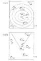
- Figs. 17 to 20 are bird's-eye views of virtual spaces, showing examples of the grading of voices into some levels of quality in accordance with the relationship between the avatar A1 and the other avatars. For the sake of brevity, this example will be described in connection with the case of classifying the voices of the other avatars in terms of sound pressure level.
- concentric circles are drawn about the avatar A1 and the voices of avatars in circles of smaller radii are graded up to higher levels of quality.
- This example uses five levels of quality. That is, the voice of the avatar A2 closest to the avatar A1 is graded up to the highest level(loss rate: 0 dB) and the voice of the avatar A3 is graded to the second highest level (loss rate: -10 dB).
- the voices of the avatars A4 and A5 (loss rate: -13 dB), the voice of the avatar A6 (loss rate: -16 dB) and the voices of the avatars A7 and A8 (loss rate: -19 dB) are thus graded down in this order.
- This processing is carried out for each of all the remaining avatars in the virtual space. While this example employs the simplest grading method which uses concentric circles, various other methods can be used. For example, the voice of an avatar in front of the noted one A1 is graded to a higher level than the voice of an avatar behind through utilization of human hearing or auditory characteristics.
- the field of vision of the avatar A1 is calculated from the direction of eyes thereof and the voices of avatars in that field of vision are preferentially graded up to higher levels.
- This example employs two levels of quality. That is, the sound pressure levels of the voices of the avatars A2, A4 and A7 are increased (loss rate: 0 dB), whereas the sound pressure levels of the voices of the avatars A3, A5, A6 and A8 not in the field of vision are decreased (loss rate: -19 dB).
- This processing is carried out for each of the other remaining avatars in the virtual space. In this case, the visual angle of each avatar is predetermined in the system.
- Fig. 19 employs the angle ⁇ between the direction of eyes or line of sight EL of the avatar A1 and a straight line joining the avatar A1 and each of the other avatars.
- the voices from the avatars of smaller angle are preferentially graded up to higher levels of quality. This example uses five levels of quality.
- This processing is carried out for each of all the other remaining avatars.
- the avatar A1 and each of the other avatars are joined by a straight line as indicated by the broken line and the line of sight of the avatar A1 is turned until it comes into alignment with the straight line and the turning angle ⁇ is calculated.
- the direction of rotation in this case is the direction in which the angle ⁇ , decreases.
- the line of sight of the other avatar is turned until it comes into alignment with the straight line and the turning angle ⁇ is calculated.
- the direction of turn in this case is the direction in which the angle ⁇ decreases.
- the voices of the avatars of the smaller angles are graded up to higher levels of quality. This example uses five levels of quality.
- Figs. 17, 18 and 20 may be used singly or in combination. With the combined use of the methods of Figs. 17, 18 and 20, for instance, it is possible to make the voice of the avatar in the field of vision of the avatar A1 larger as the distance between them decreases and as the degree of coincidence of their directions of eyes increases.
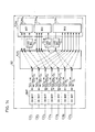
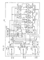
- Fig. 21 illustrates an example of the configuration of the server 50 which effects the above-described voice quality control in the centralized connection type virtual space sharing apparatus.
- the server 50 is shown to accommodate three terminals.
- the server 50 is connected to terminals 10 1 , 10 2 and 10 3 (see Figs. 2A and 2B) via the channels CH 1 , CH 2 and CH 3 and receives data therefrom in the channel interface parts INF 1 , INF 2 and INF 3 , respectively.
- the channel interface parts INF 1 to INF 3 transfer them to the position information distributing part 52A and, at the same time, write them into the table memory 53.
- the position information distributing part 52A copies the position data and direction-of-eyes data received from the channel interface part INF 1 and transfers them to the channel interface parts INF 2 and INF 3 , copies and transfers the position data and direction-of-eyes data received from the channel interface part INF 2 to those INF 1 and INF 3 , and copies and transfers the position data and direction-of-eyes data received from the channel interface part INF 3 to those INF 1 and INF 2 .
- a loss determining part 52E 1 uses the position data and direction-of-eyes data read out of the table memory 53 to calculate, by the methods described previously with reference to Figs. 17 to 20, the loss rates of voices of other users to be provided to the user of the terminal accommodated in the channel interface part INF 1 . Based on the loss rates thus determined, the loss determining part 52E 1 sends loss-inserting instructions to loss inserting parts 5L 12 and 5L 13 corresponding to the users of the terminals accommodated in the channel interface parts INF 2 and INF 3 .
- a loss determining part 52E 2 also sends loss-inserting instructions to loss inserting parts 5L 21 and 5L 23 corresponding to the users of the terminals accommodated in the channel interface parts INF 1 and INF 3 .
- a loss determining part 52E 3 similarly sends loss-inserting instructions to loss inserting parts 5L 31 and 5L 32 corresponding to the users of the terminals accommodated in the channel interface parts INF 1 and INF 2 .
- the channel interface part INF 1 analyses received data and, if it is speech data, transfers the speech data SD 1 to the loss inserting parts 5L 21 and 5L 31 .
- the channel interface part INF 2 analyses received data and, if it is speech data, transfers the speech data SD 2 to the loss inserting parts 5L 12 and 5L 32 .
- the channel interface part INF 3 similarly analyses received data and, if it is speech data, then transfers the speech data SD 3 to the loss inserting parts 5L 13 and 5L 23 .
- a speech mixing part 52M 1 mixes the speech data with the losses inserted therein by the loss inserting parts 5L 12 and 5L 13 and transfers the mixed output to the channel interface part INF 1 , from which it is sent to the terminal 10 1 via the channel CH 1 .
- a speech mixing part 52M 2 mixes the speech data with the losses inserted therein by the loss inserting parts 5L 21 and 5L 23 and transfers the mixed output to the channel interface part INF 2 , from which it is sent to the terminal 10 2 via the channel CH 2 .
- a speech mixing part 52M 3 also mixes speech data with losses inserted therein by the loss inserting parts 5L 31 and 5L 32 and transfers the mixed output to the channel interface part INF 3 , from which it is sent to the terminal 10 3 via the channel CH 3 .
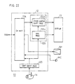
- Fig. 22 illustrates in block form an example of one terminal 10 which is connected to the server 50 shown in Fig. 21.
- the parts corresponding to those in Figs. 3 and 7 are identified by the same reference numerals and characters.
- the channel interface part 12A of the terminal control part 12 is connected via the communication network NW to the server 50 depicted in Fig. 21.
- the control input processing part 12D sends position data and direction-of-eyes data of the user's avatar inputted from the control device 14 to the server 50 via the channel interface part 12A and the communication network NW and, at the same time, sends the same data to a viewing point shift processing part 12Gv of the video image generating part 12G.
- the viewing point shift processing part 12Gv of the video image generating part 12G uses the position data and direction-of-eyes data of the avatar received from the control input processing part 12D to shift the viewing point in the virtual space and display on a display 13 video images that come into the field of vision.
- An other avatar shift processing part 12Gm forms avatar images of other users at specified positions and in specified directions in the visual field image in correspondence with position data and direction-of-eyes data of the other users' avatars received from the server 50 via the channel interface part 12A and displays them on the display 13.
- the voice received in the channel interface part 12A is outputted to the speaker SP.
- the voice of the user of this terminal inputted from the microphone MC, is sent via the channel interface part 12A to the server 50.
- FIGs. 21 and 22 show examples of the constructions of the server and the terminal for use in the centralized connection type virtual space display apparatus, the same principles described above can also be applied to the distributed connection type virtual space sharing apparatus.
- Fig. 23 illustrates an example of the configuration of one terminal 10 for use in the distributed connection type virtual space sharing apparatus which effects the afore-mentioned speech quality control.
- the number of terminals of other users is three.
- the terminal 10 of Fig. 22 sends and receives position data, direction-of-eyes data and speech data to and from the server 50 of Fig. 21 and voices are mixed in the server 50 in correspondence with respective users.
- a speech quality control part 12Q is provided in the terminal control part 12 of each user terminal and, based on the position data and/or direction-of-eyes data received from the other terminals and stored in the table memory 12E, the sound pressure level for each of the other users' avatars is determined in a loss determining part 2E by a desired one of the methods described previously with respect to Figs. 17 to 20; the losses thus determined are set in loss inserting parts 2L 1 , 2L 2 and 2L 3 , respectively.
- the pieces of speech data received from the other terminals are attenuated by the losses set in the loss inserting parts 2L 1 to 2L 3 and then mixed by a mixer 2M, thereafter being outputted to the speaker SP.
- the basic principles and operations are the same as those described previously.
- Fig. 23 lends realism to the virtual space by changing the sound pressure levels of voices of users to be mixed according to the distances and/or directions of eyes of the corresponding avatars relative to that of the user of each particular one of the terminals, it is also possible to request the speech data sending terminal or server to send the speech data of specified quality.
- Fig. 24 illustrates another example of the terminal for use in the distributed connection type system as is the case with the Fig. 23 example.
- each user terminal requests the other user terminals to send their voices of speech quality specified on the basis of the position and/or direction-of-eyes relationship between their avatars in Fig. 23.
- the requested terminals each send speech data of the specified quality to the requesting terminals--this enhances an auditory sense of reality of the mixed speech more than in the above-described examples, lending more realism to the virtual space.
- the quality of speech data to be sent can be debased according to the circumstances, an average amount of information sent can be reduced; hence, the traffic congestion of the communication network can be eased accordingly.
- the Fig. 24 example has a construction in which a speech quality requesting part 12R, a speech quality request analyzing part 12S and a speech processing part 12K are added to the Fig. 23 example.
- the speech quality requesting part 12R is supplied with speech quality determining parameters for respective avatars which are calculated from their position data and/or direction-of-eyes data in a loss determining part 2E to determine losses, such as distances from each avatar to the others; the speech quality determining part 12R determines the necessary speech quality corresponding to each distance and provides the information to a packet assembling and disassembling part 12H.
- the packet assembling and disassembling part 12H assembles into a packet a signal which requests each terminal to send speech of the determined quality and sends the packet to each terminal via the channel interface part 12A.
- the speech quality that is defined in terms of distance can be obtained, for example, by changing the transmission rate of speech data. For instance, four distance threshold values D 1 to D 4 are predetermined which bear the relationship D 1 ⁇ D 2 ⁇ D 3 ⁇ D 4 .
- Each avatar requests another avatar with the distance d in the range of d ⁇ D 1 to send speech data of a 64 Kb/s transmission rate, another avatar with the distance d in the range of D 1 ⁇ d ⁇ D 2 to send speech data of a 32 Kb/s transmission rate, another avatar with the distance d in the range of D 3 ⁇ d ⁇ D 4 to send speech data of a 16 Kb/s transmission rate and still another avatar with the distance d in the range of D 4 ⁇ d to send speech data of an 8 Kb/s transmission rate.
- the speech quality requests received from other terminals are analyzed in the speech quality request analyzing part 12S to identify the speech transmission rates requested by the individual terminals and it provides the information to the speech processing part 12K.
- the speech processing part 12K digitally processes speech signal inputted from the microphone MC to convert it into speech data of the requested bit rates, which are provided to the packet assembling and disassembling part 12H.
- the packet assembling and disassembling part 12H sends the speech data of the respective bit rates as packets addressed to the requesting terminals via the channel interface part 12A.
- the speech data packets received from the respective terminals in response to the requests of the terminal concerned are disassembled into speech data of the requested bit rates, which are provided to the loss inserting parts 2L 1 , 2L 2 and 2L 3 , respectively, wherein they are subjected to the same processing as described above in respect of the Fig. 23 example, thereafter being mixed by the mixer 2M and then provided to the speaker SP.
- the bit rate (and consequently the speech quality in terms of frequency characteristic) increases as the avatar concerned is approached--this provides enhanced sense of reality more than in the Fig. 23 example.
- the bit rate of the speech data decreases with distance from the avatar concerned. Hence, the amount of information sent is reduced as a whole and consequently the traffic congestion of the communication network is eased accordingly.
- Each user terminal picks up a high quality image of the user with a video camera, digitizes it for each frame and sends it to the server.
- the server has an image memory corresponding to each user and, upon every reception of user's image, overwrites and stores it in the image memory.
- the quality of video image is defined by the number of frames per seconds, resolution (lines/mm), or a combination thereof. The number of frames per second contributes to the smoothness of movement of the video image and the resolution contributes to its definition.
- each terminal specifies, fore each user, a different interval at which to send its video image from the server (the number of frames per second) or different resolution of the video image.
- the server sends to the requesting terminal the video image of the specified user with the specified resolution and/or the number of frames per second--this permits reduction of the amount of information that is sent throughout the system.
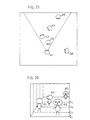
- Fig. 25 is a diagram of the virtual space viewed from above, showing how the terminal specifies the quality of the video image that it requests the server to send.
- Fig. 25 there is depicted the field of vision of the avatar A1 in the visual space.
- the avatar A2 is closest to the avatar A1 and also keeps eye contact therewith; hence, for the avatar A2, the terminal of the avatar A1 requests the server to send a video image of the highest quality.
- the terminal Since the avatar A5 is facing the avatar A1 but remains a little out of eye contact with the latter, the terminal requests the server of a video image of lower quality.
- the terminal of the avatar A1 requests the server of a video image of the lowest quality since no eye contact is not established between them.
- Fig. 26 shows display images of the visual field image that the avatar A1 observes in the virtual space depicted in Fig. 25.
- the broken lines indicate distance threshold values D 1 , D 2 , D 3 and D 4 relative to the avatar A1 (which are not displayed in practice).
- the avatar images in respective regions defined by these threshold values are each displayed in the quality determined as described previously.
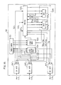
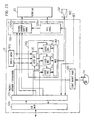
- Fig. 27 illustrates an example of the configuration of the server 50 in the virtual space sharing apparatus of the centralized connection type system.
- the server 50 is shown to accommodate three terminals and no audio-related parts are shown.
- the server 50 sends and receives position information (position coordinates and direction of eyes) and video images to and from the terminals via channels CH 1 , CH 2 and CH 3 .
- the data received from the channels CH 1 ,CH 2 and CH 3 are received in the channel interface parts INF 1 , INF 2 and INF 3 , respectively.
- the channel interface parts INF 1 to INF 3 each analyze the received data and, if it is video image data, transfer it to a video storage part 52K.
- the video storage part 52K writes the received video image in a memory which stores video images in correspondence with terminals accommodated.
- the channel interface parts INF 1 to INF 3 each transfer it to a position information distributing part 52A.
- the position information distributing part 52A copies the position information received from the channel interface part INF 1 and transfers it to the channel interface parts INF 2 and INF 3 ; the position information distributing part 52A copies the position information received from the channel interface part INF 2 and transfers it to the INF 1 and INF 3 ; and the position information distributing part 52A copies the position information received from the channel interface part INF 3 and transfers it to the channel interface parts INF 1 and INF 3 .
- the channel interface parts INF 1 to INF 2 each transfers it to an image requests analyzing part 52J.
- the image request analyzing part 52J analyzes the received request and informs the image storage part 52K of the requested image and, at the same time, informs video processing part 52N of the requested resolution and/or the number of frames per second and the requesting terminal.
- the video storage part 52K reads out of its memory the requested image specified by the image request analyzing part 52N and transfers it to the video processing part 52N.
- the video processing part 52N converts the video image received from the video storage part 52K to the resolution and/or the number of frames per second specified by the video image request analyzing part 52J and, on the basis of the specified requesting terminal information, sends the video image to the requesting terminal via the channel interface part INF 1 and the channel CH 1 , the channel interface part INF 2 and the channel CH 2 , or the channel interface part INF 3 and the channel CH 3 .
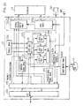
- Fig. 28 illustrates an example of the construction of the terminal in the virtual space sharing apparatus of the centralized connection type system. No audio-related parts are shown.
- the terminal 10 sends and receives video images and position information to and from the server 50 via a communication network NW and a channel CH.
- the terminal 10 picks up the video image of the user by the video camera VC and transfers it to a digital video processing part 12J.
- the digital video processing part 12J digitizes the received video image frame by frame and sends it to the server 50 via the channel interface part 12A and the channel CH.
- updated position information (coordinates and direction of eyes) is provided to the control input processing part 12D.
- the control input processing part 12D sends the position information to the server 50 via the channel interface part 12A and the channel CH. At the same time, the control input processing part 12D send the position information to the viewing point shift processing part 12Gv as well.
- the viewing point shift processing part 12Gv responds to the updated position information to change the visual field image in the virtual space to be presented to the user and displays it on the display 13.
- the control input processing part 12D sends move information to a distance/eye contact deciding part 12N.
- the channel interface part 12A transfers it to an other avatar position and direction-of-eyes analyzing part 12L.
- the other avatar position and direction-of-eyes analyzing part 12L transfers position coordinates and directions of eyes of other avatars to an other avatar shift processing part 12Gm and the distance/eye contact deciding part 12N, respectively.
- the distance/eye contact deciding part 12N operates in the same manner as do the distance decision part 52B and the eye contact deciding part 52C described previously with respect to Figs. 10 and 11.
- the distance/eye contact deciding part 12N decides the distance and/or eye contact between the user and each of the other avatars, then decides the image quality for the avatar by the method described previously in respect of Fig. 25 and requests the server 50 via the channel interface part 12A and the channel CH to send the video image of the specified quality.
- the method described previously with respect to Fig. 19 that is, as the angle ⁇ between the direction EL of eyes of the avatar of the user and each avatar increases, the resolution and/or the number of frames per time is reduced.
- the method described in respect of Fig. 20 may also be used; that is, as the sum of angles ⁇ and ⁇ between the directions of eyes of the two avatars and the straight line joining them increases, the resolution and/or the number of frames per time is reduced.
- the channel interface part 12A transfers it to the other avatar move processing part 12Gm.
- the other avatar shift processing part 12Gm changes the position and direction of eyes of each avatar, then pastes the video image (facial videos) received from the channel interface part 12A to the corresponding avatar in a size corresponding to the distance from the user's viewing point to the avatar, then converts the avatar image to the position viewed from the user's viewing point and displays it on the display 13.
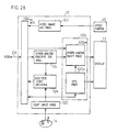
- Fig. 29 illustrates an example of the configuration of the terminal in the virtual space sharing apparatus of the distributed connection type system.
- the terminal 12 directly sends and receives video data and position information (position coordinates and direction of eyes) to and from other terminals via the communication network NW and the channel CH.
- each terminal is provided with a video storage and processing part 12Q and a video request analyzing part 12R in place of the digital video processing part 12J.
- the video camera VC picks up video of the user and transfers it to the video storage and processing part 12Q.
- the video storage and processing part 12Q digitizes the received video image on a framewise basis and stores it.
- the channel interface part 12A transfers the request information to the video request analyzing part 12R.
- the video request analyzing part 12R analyzes the received request and informs the image storage and processing part 12Q of the requested resolution and the requesting terminal.
- the video storage and processing part 12Q converts its stored video image to the specified resolution and/or number of frames per time and sends it to the requesting terminal via the channel interface 12A and the channel CH.
- each terminal in the distributed connection type system or the server in the centralized connection type system stores high-quality video of each user in its memory and, only when requested by each terminal, sends the video in specified quality.
- these embodiments effectively avoid the traffic congestion of the communication network and lessen the burden of processing for receiving video images at the terminal, resulting in the effect of preventing degradation of image quality.
- the on-demand system has been described, but when the on-demand system is not utilized, since in the centralized connection type systems of Figs. 27 and 28 the latest position information of avatars of all terminals is stored in the position information distributing part 52A of the server 50 in Fig. 27, the distances between the avatar of each terminal and the avatars of the other terminals are calculated through the use of the stored position information, then the levels of resolution and/or the numbers of frames per second of the video images to be sent to each terminal from the others are determined according to the distances between them, and the video images are processed in the video processing part 52K accordingly. In this instance, the distance/eye contact decision part 12N need not be provided in the terminal of Fig. 28.
- the levels of image quality of the avatar of each terminal user relative to the avatars of the other users are determined in the distance/eye contact deciding part 12N on the basis of the relationship between the position information of the avatars of the other users received in the terminal of Fig. 29 from the other terminals and the position information of the avatar of the user of this terminal, and the video image of the terminal user is sent at the determined levels of quality from the video storage and processing part 12O to the other terminals, respectively.
- the video image request analyzing part 12R is not needed and, as indicated by the broken line, the distance/eye contact decision part 12N informs the video storage and processing part 12Q of the determined image quality.
Landscapes
- Engineering & Computer Science (AREA)
- Physics & Mathematics (AREA)
- Theoretical Computer Science (AREA)
- Multimedia (AREA)
- Signal Processing (AREA)
- Geometry (AREA)
- Computer Graphics (AREA)
- General Physics & Mathematics (AREA)
- Computer Networks & Wireless Communication (AREA)
- Software Systems (AREA)
- Information Transfer Between Computers (AREA)
- Processing Or Creating Images (AREA)
- Computer And Data Communications (AREA)
- Telephonic Communication Services (AREA)
Claims (14)
- Vorrichtung zur gemeinsamen Benutzung eines virtuellen Raums, die eine Mehrzahl von mit einem Kommunikationsnetzwerk (NW) verbundenen Terminals (101 - 103) und eine durch das Kommunikationsnetzwerk an die jeweiligen Terminals angeschlossene Server-Anordnung (50) aufweist, wobei die Terminals einen vorbestimmten gemeinsamen virtuellen Raum gemeinsam benutzen und jedes Terminal ein Gesichtsfeldbild erzeugt und anzeigt, das sich ändert, wenn ein jeweiliger Avatar (A1 - A3), der einen Benutzer des jeweiligen Terminals repräsentiert, sich in dem virtuellen Raum an dem jeweiligen Terminal bewegt, wobei
jedes Terminal umfaßt:die Server-Anordnung (50) umfaßt:eine Sende- und Empfangsanordnung (12A), die Videobilddaten des Benutzers des jeweiligen Terminals und Positionsinformation des jeweiligen Avatars an die Server-Anordnung (50) sendet und Videobilddaten der Benutzer der anderen Terminals sowie Positionsinformation von deren Avataren von der Server-Anordnung empfängt;eine Kameraanordnung (VC), die das Videobild des Benutzers des jeweiligen Terminals aufnimmt und ein Videosignal ausgibt;eine Videoverarbeitungsanordnung (12J), die das Videosignal digital verarbeitet und es über die Sende- und Empfangsanordnung an die Server-Anordnung (50) sendet;eine Qualitätsspezifizierungs- und Videoanforderungsanordnung (12N), welche die Bildqualität für den Avatar jedes der anderen Terminalbenutzer auf der Basis der Beziehung zwischen der Positionsinformation jenes Avatars und der Positionsinformation des jeweiligen Avatars ermittelt und über die Sende- und Empfangsanordnung an die Server-Anordnung (50) ein Videoanforderungssignal sendet, mit dem ein Videobild mit der ermittelten Qualität angefordert wird; undeine Anordnung (12Gm), die ein Avatarbild auf der Basis der von der Server-Anordnung empfangenen Videobilddaten jedes der anderen Terminalbenutzer erzeugt und es in einem Gesichtsfeldbild des Benutzers des jeweiligen Terminals an einer Position anzeigt, die durch die Positionsinformation des Avatars des entsprechenden anderen Terminalbenutzers spezifiziert ist; undeine Positionsinformationsverteilungsanordnung (52A), die von dem jeweiligen Terminal empfangene Positionsinformation des jeweiligen Avatars an alle anderen Terminals sendet;eine Videospeicheranordnung (52K), die Videobilddaten entsprechend den Terminals (101 - 103) speichert;eine Anordnung, die empfangene Videobilddaten in die Videospeicheranordnung schreibt; undeine Qualitätsverarbeitungsanordnung (52J, 52N), die ein jeweiliges Videobildanforderungssignal analysiert, das von den einzelnen anderen Terminals empfangen wurde, dann die angeforderten Videobilddaten aus der Videospeicheranordnung ausliest und sie an das anfordernde Terminal sendet, nachdem sie so bearbeitet wurden, daß sie die spezifizierte Qualität aufweisen. - Vorrichtung zur gemeinsamen Benutzung eines virtuellen Raums, die eine Mehrzahl von über ein Kommunikationsnetzwerk (NW) untereinander verbundenen Terminals (101 - 103) aufweist, wobei die Terminals einen vorbestimmten gemeinsamen virtuellen Raum gemeinsam benutzen und jedes Terminal ein Gesichtsfeldbild erzeugt und anzeigt, das sich ändert, wenn ein jeweiliger Avatar (A1 - A3), der einen Benutzer des jeweiligen Terminals repräsentiert, sich in dem virtuellen Raum an dem jeweiligen Terminal bewegt, wobei jedes Terminal umfaßt:eine Sende- und Empfangsanordnung (12A), die Videobilddaten des Benutzers des jeweiligen Terminals und Positionsinformation des jeweiligen Avatars an die anderen Terminals sendet und Videobilddaten der Benutzer der anderen Terminals sowie Positionsinformation von deren Avataren empfängt;eine Qualitätsspezifizierungs- und Videoanforderungsanordnung (12N), welche die Bildqualität für den Avatar jedes der anderen Terminalbenutzer auf der Basis der Beziehung zwischen der von dem entsprechenden anderen Terminal empfangenen Positionsinformation jenes Avatars und der Positionsinformation des jeweiligen Avatars ermittelt und über die Sende- und Empfangsanordnung an jedes der anderen Terminals ein Videoanforderungssignal sendet, mit dem ein Videobild mit der ermittelten Qualität angefordert wird;eine Videospeicheranordnung (12Q), die Videodaten speichert;eine Kameraanordnung (VC), die das Videobild des Benutzers des jeweiligen Terminals aufnimmt;eine Videoverarbeitungsanordnung (12Q), die das Videosignal digital verarbeitet und es in die Videospeicheranordnung schreibt;eine Anordnung (12R, 12Q), die ein von einem anderen Terminal empfangenes Videobildanforderungssignal analysiert, dann die angeforderten Videobilddaten aus der Videospeicheranordnung ausliest und sie an das anfordernde Terminal sendet, nachdem sie so bearbeitet worden sind, daß sie die spezifizierte Qualität aufweisen; undeine Anordnung (12Gm), die ein Avatarbild auf der Basis der von den anderen Terminals empfangenen Videobilddaten jedes der anderen Terminalbenutzer erzeugt und es in einem Gesichtsfeldbild des Benutzers des jeweiligen Terminals an einer Position anzeigt, die durch die vom entsprechenden anderen Terminal empfangenen Positionsinformation spezifiziert ist.
- Vorrichtung nach Anspruch 1 oder 2, bei der die Bildqualität die Auflösung des Videobilds ist.
- Vorrichtung nach Anspruch 1 oder 2, bei der die Bildqualität die Anzahl an Rahmen der Videobilddaten pro Zeiteinheit ist.
- Vorrichtung nach Anspruch 1 oder 2, bei der die Positionsinformation eines Avatars (A1 - A3) dessen Positionskoordinaten umfaßt und die Qualitätsspezifizierungs- und Videoanforderungsanordnung eine Anordnung umfaßt, welche die Bildqualität jedes der anderen Terminalbenutzer so ermittelt, daß dessen Bildqualität mit zunehmender Länge einer geraden Linie abnimmt, welche die Positionskoordinaten des jeweiligen Avatars und die Positionskoordinaten des Avatars des entsprechenden anderen Terminalbenutzers im Gesichtsfeld des erstgenannten verbindet.
- Vorrichtung nach Anspruch 1 oder 2, bei der die Positionsinformation eines Avatars (A1 - A3) dessen Positionskoordinaten umfaßt und die Qualitätsspezifizierungs- und Videoanforderungsanordnung eine Anordnung umfaßt, welche die Bildqualität jedes der anderen Terminalbenutzer so ermittelt, daß die Bildqualität mit einer Zunahme des Winkels zwischen der Augenrichtung des jeweiligen Avatars und der Position des Avatars des entsprechenden anderen Terminalbenutzers im Gesichtsfeld des erstgenannten abnimmt.
- Vorrichtung nach Anspruch 1 oder 2, bei der die Positionsinformation eines Avatars (A1 - A3) dessen Positionskoordinaten und die Augenrichtung umfaßt und die Qualitätsspezifizierungs- und Videobildanforderungsanordnung eine Anordnung umfaßt, welche die Bildqualität jedes der anderen Terminalbenutzer so ermittelt, daß die Bildqualität mit einer Zunahme der Summe des Drehwinkels der Augenrichtung des jeweiligen Avatars und desjenigen des Avatars des entsprechenden anderen Terminalbenutzers im Gesichtsfeld des jeweiligen Avatars zu einer geraden Linie abnimmt, welche deren Koordinaten verbindet.
- Anzeigeverfahren für einen virtuellen Raum, der durch eine Mehrzahl von Terminals (101 - 103) definiert ist, die über ein Kommunikationsnetzwerk (NW) mit einer Server-Anordnung (50) verbundenen sind und einen vorbestimmten gemeinsamen virtuellen Raum gemeinsam benutzen, wobei jedes Terminal ein Gesichtsfeldbild erzeugt und anzeigt, das sich ändert, wenn ein jeweiliger Avatar (A1 - A3), der einen Benutzer des jeweiligen Terminals repräsentiert, sich in dem virtuellen Raum an dem jeweiligen Terminal bewegt,
wobei jedes Terminal folgende Schritte ausführt:(a) Aufnehmen des Videobilds des Benutzers des jeweiligen Terminals, digitales Verarbeiten des Videosignals und Senden der Videobilddaten des Benutzers an die Server-Anordnung (50);(b) Senden von Positionsinformation des jeweiligen Avatars des jeweiligen Terminals an die Server-Anordnung (50);(c) Empfangen von Positionsinformation des Avatars jedes Benutzers der anderen Terminals von der Server-Anordnung;(d) Ermitteln der Bildqualität für den Avatar jedes der anderen Terminalbenutzer auf der Basis der Beziehung zwischen der Positionsinformation des Avatars eines jeweiligen anderen Terminalbenutzers und der Positionsinformation des jeweiligen Avatars;(e) Senden eines Videoanforderungssignals, mit dem ein Videobild mit der ermittelten Qualität angefordert wird, an die Server-Anordnung (50); und(f) Erzeugen eines Avatarbilds auf der Basis der von der Server-Anordnung (50) empfangenen Videobilddaten jedes der anderen Terminalbenutzer und dessen Anzeige in einem Gesichtsfeldbild des Benutzers des jeweiligen Terminals an der durch die Positionsinformation des Avatars der entsprechenden anderen Terminalbenutzer spezifizierten Position; und
wobei die Server-Anordnung (50) folgende Schritte ausführt:(g) Schreiben von Videobilddaten, die von den einzelnen Terminals empfangen wurden, diesen zugeordnet, in eine Videospeicheranordnung (52K);(h) Senden von Positionsinformation des Avatars des jeweiligen Benutzers, die von den einzelnen Terminals empfangen wurde, an alle anderen Terminals; und(i) Analysieren eines von jedem der anderen Terminals empfangenen Videobildanforderungssignals, anschließendes Auslesen der angeforderten Videobilddaten aus der Videospeicheranordnung und deren Senden an das anfordernde Terminal, nachdem sie so verarbeitet worden sind, daß sie die spezifizierte Qualität aufweisen. - Anzeigeverfahren für einen virtuellen Raum, der durch eine Mehrzahl von Terminals (101 - 103) definiert ist, die über ein Kommunikationsnetzwerk (NW) untereinander verbunden sind und einen vorbestimmten gemeinsamen virtuellen Raum gemeinsam benutzen, wobei jedes Terminal ein Gesichtsfeldbild erzeugt und anzeigt, das sich ändert, wenn ein jeweiliger Avatar (A1 - A3), der einen Benutzer des jeweiligen Terminals repräsentiert, sich in dem virtuellen Raum an dem jeweiligen Terminal bewegt, wobei jedes Terminal folgende Schritte ausführt:(a) Aufnehmen des Videobilds des Benutzers des jeweiligen Terminals, digitales Verarbeiten des Videosignals und dessen Schreiben in eine Videospeicheranordnung;(b) Senden von Positionsinformation des jeweiligen Avatars an die anderen Terminals;(c) Empfangen von Positionsinformation des Avatars des jeweiligen Benutzers jedes der anderen Terminals;(d) Ermitteln der Bildqualität für den Avatar jedes der anderen Terminalbenutzer auf der Basis der Beziehung zwischen der Positionsinformation des Avatars des entsprechenden anderen Terminalbenutzers und der Positionsinformation des jeweiligen Avatars;(e) Senden eines Videoanforderungssignals, mit dem ein Videobild mit der ermittelten Qualität angefordert wird, an jedes der anderen Terminals;(f) Empfangen des Videoanforderungssignals von jedem der anderen Terminals;(g) Senden der aus der Videospeicheranordnung ausgelesenen Videodaten an die anfordernden Terminals, nachdem sie so bearbeitet worden sind, daß sie die von dem Videoanforderungssignal spezifizierte Qualität aufweisen; und(h) Erzeugen eines Avatarbilds auf der Basis der Videobilddaten jedes der anderen Terminalbenutzer, die von ihnen empfangen wurden, und dessen Anzeige in einem Gesichtsfeldbild des Benutzers des jeweiligen Terminals an der durch die Positionsinformation des Avatars des entsprechenden anderen Terminalbenutzers spezifizierten Position.
- Verfahren nach Anspruch 8 oder 9, bei dem die Bildqualität die Auflösung des Videobilds ist.
- Verfahren nach Anspruch 8 oder 9, bei dem die Bildqualität die Anzahl an Rahmen der Videobilddaten pro Zeiteinheit ist.
- Verfahren nach Anspruch 8 oder 9, bei dem die Positionsinformation eines Avatars (A1 - A3) dessen Positionskoordinaten umfaßt und Schritt (d) einen Schritt der Bestimmung der Bildqualität jedes der anderen Terminalbenutzer so umfaßt, daß dessen Bildqualität mit zunehmender Länge einer geraden Linie abnimmt, welche die Positionskoordinaten des jeweiligen Avatars und die Positionskoordinaten des Avatars des entsprechenden anderen Terminalbenutzers im Gesichtsfeld des erstgenannten verbindet.
- Verfahren nach Anspruch 8 oder 9, bei dem die Positionsinformation eines Avatars (A1 - A3) dessen Positionskoordinaten und die Augenrichtung umfaßt und Schritt (d) einen Schritt der Bestimmung der Bildqualität jedes der anderen Terminalbenutzer so umfaßt, daß die Bildqualität mit einer Zunahme des Winkels zwischen der Augenrichtung des jeweiligen Avatars und der Position des Avatars des entsprechenden anderen Terminalbenutzers im Gesichtsfeld des erstgenannten abnimmt.
- Verfahren nach Anspruch 8 oder 9, bei dem die Positionsinformation eines Avatars (A1 - A3) dessen Positionskoordinaten und die Augenrichtung umfaßt und Schritt (d) einen Schritt der Bestimmung der Bildqualität jedes der anderen Terminalbenutzer so umfaßt, daß die Bildqualität mit einer Zunahme der Summe des Drehwinkels der Augenrichtung des jeweiligen Avatars und desjenigen des Avatars des entsprechenden anderen Terminalbenutzers im Gesichtsfeld des jeweiligen Avatars zu einer geraden Linie abnimmt, welche deren Koordinaten verbindet.
Priority Applications (2)
| Application Number | Priority Date | Filing Date | Title |
|---|---|---|---|
| EP99112201A EP0942396B1 (de) | 1994-08-03 | 1995-08-02 | Anzeigeverfahren für einen gemeinsamen virtuellen Raum und Vorrichtung unter Verwendung dieses Verfahrens |
| EP99112202A EP0942397B1 (de) | 1994-08-03 | 1995-08-02 | Anzeigeverfahren fur einen gemeinsamen virtuellen Raum und Vorrichtung unter Verwendung dieses Verfahrens |
Applications Claiming Priority (15)
| Application Number | Priority Date | Filing Date | Title |
|---|---|---|---|
| JP182058/94 | 1994-08-03 | ||
| JP6182058A JP3027793B2 (ja) | 1994-08-03 | 1994-08-03 | 仮想空間共有装置 |
| JP18205894 | 1994-08-03 | ||
| JP6325858A JP3019291B2 (ja) | 1994-12-27 | 1994-12-27 | 仮想空間共有装置 |
| JP325858/94 | 1994-12-27 | ||
| JP32585894 | 1994-12-27 | ||
| JP4235/95 | 1995-01-13 | ||
| JP00423595A JP3182736B2 (ja) | 1994-01-14 | 1995-01-13 | 仮想空間表示システム |
| JP423595 | 1995-01-13 | ||
| JP15050195A JP3183496B2 (ja) | 1995-06-16 | 1995-06-16 | 仮想空間共有システム |
| JP15050195 | 1995-06-16 | ||
| JP150501/95 | 1995-06-16 | ||
| JP169919/95 | 1995-07-05 | ||
| JP7169919A JP3070719B2 (ja) | 1995-07-05 | 1995-07-05 | 仮想空間共有方法およびこの方法を実施する装置 |
| JP16991995 | 1995-07-05 |
Related Child Applications (2)
| Application Number | Title | Priority Date | Filing Date |
|---|---|---|---|
| EP99112201A Division EP0942396B1 (de) | 1994-08-03 | 1995-08-02 | Anzeigeverfahren für einen gemeinsamen virtuellen Raum und Vorrichtung unter Verwendung dieses Verfahrens |
| EP99112202A Division EP0942397B1 (de) | 1994-08-03 | 1995-08-02 | Anzeigeverfahren fur einen gemeinsamen virtuellen Raum und Vorrichtung unter Verwendung dieses Verfahrens |
Publications (3)
| Publication Number | Publication Date |
|---|---|
| EP0696018A2 EP0696018A2 (de) | 1996-02-07 |
| EP0696018A3 EP0696018A3 (de) | 1997-05-14 |
| EP0696018B1 true EP0696018B1 (de) | 2001-06-20 |
Family
ID=27518464
Family Applications (3)
| Application Number | Title | Priority Date | Filing Date |
|---|---|---|---|
| EP99112202A Expired - Lifetime EP0942397B1 (de) | 1994-08-03 | 1995-08-02 | Anzeigeverfahren fur einen gemeinsamen virtuellen Raum und Vorrichtung unter Verwendung dieses Verfahrens |
| EP99112201A Expired - Lifetime EP0942396B1 (de) | 1994-08-03 | 1995-08-02 | Anzeigeverfahren für einen gemeinsamen virtuellen Raum und Vorrichtung unter Verwendung dieses Verfahrens |
| EP95112163A Expired - Lifetime EP0696018B1 (de) | 1994-08-03 | 1995-08-02 | Anzeigeverfahren für einen gemeinsamen virtuellen Raum und Vorrichtung unter Verwendung dieses Verfahrens |
Family Applications Before (2)
| Application Number | Title | Priority Date | Filing Date |
|---|---|---|---|
| EP99112202A Expired - Lifetime EP0942397B1 (de) | 1994-08-03 | 1995-08-02 | Anzeigeverfahren fur einen gemeinsamen virtuellen Raum und Vorrichtung unter Verwendung dieses Verfahrens |
| EP99112201A Expired - Lifetime EP0942396B1 (de) | 1994-08-03 | 1995-08-02 | Anzeigeverfahren für einen gemeinsamen virtuellen Raum und Vorrichtung unter Verwendung dieses Verfahrens |
Country Status (4)
| Country | Link |
|---|---|
| US (1) | US5736982A (de) |
| EP (3) | EP0942397B1 (de) |
| CA (1) | CA2155254C (de) |
| DE (3) | DE69521369T2 (de) |
Cited By (1)
| Publication number | Priority date | Publication date | Assignee | Title |
|---|---|---|---|---|
| WO2003058473A1 (en) * | 2002-01-09 | 2003-07-17 | Lake Technology Limited | Interactive spatalized audiovisual system |
Families Citing this family (240)
| Publication number | Priority date | Publication date | Assignee | Title |
|---|---|---|---|---|
| US7859551B2 (en) * | 1993-10-15 | 2010-12-28 | Bulman Richard L | Object customization and presentation system |
| US5956028A (en) * | 1995-09-14 | 1999-09-21 | Fujitsu Ltd. | Virtual space communication system, three-dimensional image display method, and apparatus therefor |
| US6219045B1 (en) * | 1995-11-13 | 2001-04-17 | Worlds, Inc. | Scalable virtual world chat client-server system |
| US6183364B1 (en) * | 1995-12-21 | 2001-02-06 | Karen I. Trovato | Simulated environment using procedural animation in a simulated city |
| US6323857B1 (en) | 1996-04-19 | 2001-11-27 | U.S. Philips Corporation | Method and system enabling users to interact, via mutually coupled terminals, by reference to a virtual space |
| US6374255B1 (en) * | 1996-05-21 | 2002-04-16 | Immersion Corporation | Haptic authoring |
| US6314411B1 (en) * | 1996-06-11 | 2001-11-06 | Pegasus Micro-Technologies, Inc. | Artificially intelligent natural language computational interface system for interfacing a human to a data processor having human-like responses |
| US6222939B1 (en) | 1996-06-25 | 2001-04-24 | Eyematic Interfaces, Inc. | Labeled bunch graphs for image analysis |
| JPH1040197A (ja) * | 1996-07-19 | 1998-02-13 | Fujitsu Ltd | 通信管理装置 |
| US6229533B1 (en) * | 1996-08-02 | 2001-05-08 | Fujitsu Limited | Ghost object for a virtual world |
| US6154211A (en) * | 1996-09-30 | 2000-11-28 | Sony Corporation | Three-dimensional, virtual reality space display processing apparatus, a three dimensional virtual reality space display processing method, and an information providing medium |
| US5926179A (en) * | 1996-09-30 | 1999-07-20 | Sony Corporation | Three-dimensional virtual reality space display processing apparatus, a three-dimensional virtual reality space display processing method, and an information providing medium |
| US6437777B1 (en) | 1996-09-30 | 2002-08-20 | Sony Corporation | Three-dimensional virtual reality space display processing apparatus, a three-dimensional virtual reality space display processing method, and an information providing medium |
| US6954906B1 (en) * | 1996-09-30 | 2005-10-11 | Sony Corporation | Image display processing apparatus that automatically changes position of sub-window relative to main window depending on distance at watch sub window is commanded to be displayed |
| US6057856A (en) * | 1996-09-30 | 2000-05-02 | Sony Corporation | 3D virtual reality multi-user interaction with superimposed positional information display for each user |
| US20010055039A1 (en) * | 1996-09-30 | 2001-12-27 | Koichi Matsuda | Three-dimensional virtual reality space display processing apparatus, a three-dimensional virtual reality space display processing method, and an information providing medium |
| US6025801A (en) * | 1996-10-01 | 2000-02-15 | Philips Electronics North America Corporation | Video game with local updates mitigates latency effects in wide area network |
| US6317127B1 (en) | 1996-10-16 | 2001-11-13 | Hughes Electronics Corporation | Multi-user real-time augmented reality system and method |
| US20010044725A1 (en) * | 1996-11-19 | 2001-11-22 | Koichi Matsuda | Information processing apparatus, an information processing method, and a medium for use in a three-dimensional virtual reality space sharing system |
| JP3745475B2 (ja) * | 1996-12-06 | 2006-02-15 | 株式会社セガ | ゲーム装置及び画像処理装置 |
| US5812126A (en) * | 1996-12-31 | 1998-09-22 | Intel Corporation | Method and apparatus for masquerading online |
| US6271843B1 (en) * | 1997-05-30 | 2001-08-07 | International Business Machines Corporation | Methods systems and computer program products for transporting users in three dimensional virtual reality worlds using transportation vehicles |
| US6094677A (en) * | 1997-05-30 | 2000-07-25 | International Business Machines Corporation | Methods, systems and computer program products for providing insertions during delays in interactive systems |
| IL121178A (en) * | 1997-06-27 | 2003-11-23 | Nds Ltd | Interactive game system |
| US6094196A (en) * | 1997-07-03 | 2000-07-25 | International Business Machines Corporation | Interaction spheres of three-dimensional objects in three-dimensional workspace displays |
| GB2346526B (en) * | 1997-07-25 | 2001-02-14 | Motorola Inc | Method and apparatus for providing virtual actors using neural network and text-to-linguistics |
| GB9722343D0 (en) | 1997-10-22 | 1997-12-17 | British Telecomm | Distributed virtual environment |
| JPH11154178A (ja) * | 1997-11-19 | 1999-06-08 | Fujitsu Ltd | 通信管理装置及び記録媒体 |
| US6366285B1 (en) * | 1997-11-21 | 2002-04-02 | International Business Machines Corporation | Selection by proximity with inner and outer sensitivity ranges |
| US6091410A (en) * | 1997-11-26 | 2000-07-18 | International Business Machines Corporation | Avatar pointing mode |
| US6270414B2 (en) * | 1997-12-31 | 2001-08-07 | U.S. Philips Corporation | Exoskeletal platform for controlling multi-directional avatar kinetics in a virtual environment |
| GB9800397D0 (en) * | 1998-01-09 | 1998-03-04 | Philips Electronics Nv | Virtual environment viewpoint control |
| JPH11212934A (ja) * | 1998-01-23 | 1999-08-06 | Sony Corp | 情報処理装置および方法、並びに提供媒体 |
| US6329986B1 (en) * | 1998-02-21 | 2001-12-11 | U.S. Philips Corporation | Priority-based virtual environment |
| US6396509B1 (en) * | 1998-02-21 | 2002-05-28 | Koninklijke Philips Electronics N.V. | Attention-based interaction in a virtual environment |
| US6625299B1 (en) | 1998-04-08 | 2003-09-23 | Jeffrey Meisner | Augmented reality technology |
| CA2327304A1 (en) | 1998-04-13 | 1999-10-21 | Johannes Bernhard Steffens | Wavelet-based facial motion capture for avatar animation |
| US6272231B1 (en) | 1998-11-06 | 2001-08-07 | Eyematic Interfaces, Inc. | Wavelet-based facial motion capture for avatar animation |
| US6301370B1 (en) | 1998-04-13 | 2001-10-09 | Eyematic Interfaces, Inc. | Face recognition from video images |
| SE521209C2 (sv) | 1998-06-05 | 2003-10-14 | Ericsson Telefon Ab L M | Anordning och förfarande för användning i en virtuell miljö |
| GB9817834D0 (en) * | 1998-08-14 | 1998-10-14 | British Telecomm | Predicting avatar movement in a distributed virtual environment |
| JP4232232B2 (ja) * | 1998-09-30 | 2009-03-04 | ソニー株式会社 | 情報処理装置および方法、並びに記録媒体 |
| JP2000113221A (ja) * | 1998-09-30 | 2000-04-21 | Sony Corp | 情報処理装置および方法、並びに提供媒体 |
| US7050655B2 (en) * | 1998-11-06 | 2006-05-23 | Nevengineering, Inc. | Method for generating an animated three-dimensional video head |
| US6714661B2 (en) | 1998-11-06 | 2004-03-30 | Nevengineering, Inc. | Method and system for customizing facial feature tracking using precise landmark finding on a neutral face image |
| US6857572B2 (en) * | 1998-12-03 | 2005-02-22 | Metrologic Instruments, Inc. | Automatically-activated hand-supportable laser scanning bar code symbol reading system with omnidirectional and unidirectional scanning modes in addition to a data transmission activation switch |
| US7111786B2 (en) | 1998-12-03 | 2006-09-26 | Metrologic Instruments, Inc. | Automatically-activated wireless hand-supportable laser scanning bar code symbol reading system with data transmission activation switch and automatic communication range dependent control |
| AU1930600A (en) * | 1998-12-03 | 2000-06-19 | Metrologic Instruments, Inc. | Automatically-activated hand-supportable laser scanning bar code symbol reading system having data-transmission activation switch |
| US7050624B2 (en) * | 1998-12-04 | 2006-05-23 | Nevengineering, Inc. | System and method for feature location and tracking in multiple dimensions including depth |
| US6415188B1 (en) | 1998-12-23 | 2002-07-02 | Dennis Sunga Fernandez | Method and apparatus for multi-sensor processing |
| US7143358B1 (en) * | 1998-12-23 | 2006-11-28 | Yuen Henry C | Virtual world internet web site using common and user-specific metrics |
| GB2351216B (en) * | 1999-01-20 | 2002-12-04 | Canon Kk | Computer conferencing apparatus |
| GB2351635B (en) * | 1999-01-20 | 2003-03-19 | Canon Kk | Video conferencing apparatus |
| US7139767B1 (en) | 1999-03-05 | 2006-11-21 | Canon Kabushiki Kaisha | Image processing apparatus and database |
| JP3368226B2 (ja) * | 1999-03-26 | 2003-01-20 | キヤノン株式会社 | 情報処理方法及び情報処理装置 |
| JP2000279637A (ja) | 1999-03-30 | 2000-10-10 | Square Co Ltd | ゲーム装置、ゲーム表示制御方法、およびコンピュータ読取り可能な記録媒体 |
| GB2349055B (en) | 1999-04-16 | 2004-03-24 | Mitel Corp | Virtual meeting rooms with spatial audio |
| US7006616B1 (en) | 1999-05-21 | 2006-02-28 | Terayon Communication Systems, Inc. | Teleconferencing bridge with EdgePoint mixing |
| US6466695B1 (en) | 1999-08-04 | 2002-10-15 | Eyematic Interfaces, Inc. | Procedure for automatic analysis of images and image sequences based on two-dimensional shape primitives |
| US7136080B1 (en) * | 1999-09-02 | 2006-11-14 | Sony Computer Entertainment Inc. | Entertainment system, entertainment apparatus, recording medium, and program providing color coded display messages |
| JP3842493B2 (ja) * | 1999-10-04 | 2006-11-08 | 富士通株式会社 | 3次元オブジェクト共有処理方法及び記憶媒体 |
| JP3450760B2 (ja) * | 1999-10-14 | 2003-09-29 | 富士通株式会社 | コミュニケーション促進方法及びシステム |
| JP4221852B2 (ja) * | 1999-11-24 | 2009-02-12 | ソニー株式会社 | 仮想空間システム、仮想空間制御装置、仮想空間制御方法、及び記録媒体 |
| US6928087B2 (en) * | 2000-02-10 | 2005-08-09 | Telefonaktiebolaget Lm Ericsson (Publ) | Method and apparatus for automatic cross-media selection and scaling |
| US7210104B2 (en) * | 2000-02-16 | 2007-04-24 | Sega Corporation | Information display method and information display system for finding another user in a plurality of users based upon registered information |
| US6539354B1 (en) | 2000-03-24 | 2003-03-25 | Fluent Speech Technologies, Inc. | Methods and devices for producing and using synthetic visual speech based on natural coarticulation |
| US6970931B1 (en) | 2000-04-03 | 2005-11-29 | International Business Machines Corporation | Method for translucent online interaction |
| JP4479051B2 (ja) * | 2000-04-28 | 2010-06-09 | ソニー株式会社 | 情報処理装置および方法、並びに記録媒体 |
| US6784901B1 (en) | 2000-05-09 | 2004-08-31 | There | Method, system and computer program product for the delivery of a chat message in a 3D multi-user environment |
| US20060067500A1 (en) * | 2000-05-15 | 2006-03-30 | Christofferson Frank C | Teleconferencing bridge with edgepoint mixing |
| DE10026489A1 (de) * | 2000-05-27 | 2001-12-06 | Bosch Gmbh Robert | Verfahren zum Betrieb einer Videokonferenz und Vorrichtung zur Durchführung einer Videokonferenz |
| US6453294B1 (en) | 2000-05-31 | 2002-09-17 | International Business Machines Corporation | Dynamic destination-determined multimedia avatars for interactive on-line communications |
| WO2001093209A1 (de) * | 2000-06-02 | 2001-12-06 | Eidgenössische Technische Hochschule Zürich, Gruppe Für Graphische Datenverarbeitung, Institut Für Wissenschaftliches Rechnen, | Verfahren zur bereitstellung einer virtual-reality-umgebung |
| US20020008716A1 (en) * | 2000-07-21 | 2002-01-24 | Colburn Robert A. | System and method for controlling expression characteristics of a virtual agent |
| US20020015003A1 (en) * | 2000-08-07 | 2002-02-07 | Masami Kato | Virtual space system structured by plural user terminals and server device |
| JP2002082840A (ja) * | 2000-09-06 | 2002-03-22 | Sony Corp | 個人情報保護方法 |
| US7249180B2 (en) * | 2000-09-14 | 2007-07-24 | International Business Machines Corporation | Method and system for marketplace social proxies |
| US6731307B1 (en) * | 2000-10-30 | 2004-05-04 | Koninklije Philips Electronics N.V. | User interface/entertainment device that simulates personal interaction and responds to user's mental state and/or personality |
| US6910186B2 (en) | 2000-12-08 | 2005-06-21 | Kyunam Kim | Graphic chatting with organizational avatars |
| US7251788B2 (en) * | 2000-12-21 | 2007-07-31 | Nokia Corporation | Simulated speed-of-light delay for recreational benefit applications |
| FR2819920B1 (fr) * | 2001-01-22 | 2003-04-04 | France Telecom | Procede et dispositif d'animation d'avatar pour assurer la communication dans un environnement virtuel collaboratif non-immersif |
| GB2374505B (en) * | 2001-01-29 | 2004-10-20 | Hewlett Packard Co | Audio announcements with range indications |
| DE10106072A1 (de) * | 2001-02-09 | 2002-08-14 | Deutsche Telekom Ag | Verfahren zur Darstellung visueller Informationen in einer Telekommunikationsvorrichtung und Telekommunikationsvorrichtung |
| US6917703B1 (en) | 2001-02-28 | 2005-07-12 | Nevengineering, Inc. | Method and apparatus for image analysis of a gabor-wavelet transformed image using a neural network |
| WO2002078328A1 (fr) * | 2001-03-26 | 2002-10-03 | Fujitsu Limited | Processeur d'informations multicanal |
| US7392287B2 (en) * | 2001-03-27 | 2008-06-24 | Hemisphere Ii Investment Lp | Method and apparatus for sharing information using a handheld device |
| US8108509B2 (en) * | 2001-04-30 | 2012-01-31 | Sony Computer Entertainment America Llc | Altering network transmitted content data based upon user specified characteristics |
| US20020175911A1 (en) * | 2001-05-22 | 2002-11-28 | Light John J. | Selecting a target object in three-dimensional space |
| US7266532B2 (en) * | 2001-06-01 | 2007-09-04 | The General Hospital Corporation | Reconfigurable autonomous device networks |
| US6834115B2 (en) | 2001-08-13 | 2004-12-21 | Nevengineering, Inc. | Method for optimizing off-line facial feature tracking |
| US6876364B2 (en) | 2001-08-13 | 2005-04-05 | Vidiator Enterprises Inc. | Method for mapping facial animation values to head mesh positions |
| US6853379B2 (en) * | 2001-08-13 | 2005-02-08 | Vidiator Enterprises Inc. | Method for mapping facial animation values to head mesh positions |
| US7080124B1 (en) | 2001-08-21 | 2006-07-18 | Amazon Technologies, Inc. | Digital media resource messaging |
| US20030087602A1 (en) * | 2001-11-05 | 2003-05-08 | Palm, Inc. | Data prioritization and distribution limitation system and method |
| US6816159B2 (en) * | 2001-12-10 | 2004-11-09 | Christine M. Solazzi | Incorporating a personalized wireframe image in a computer software application |
| US7093007B2 (en) * | 2001-12-21 | 2006-08-15 | Hewlett-Packard Development Company, L.P. | Identifying a physical device's avatar using a unique, substantially non-removable communication identifier |
| US20030177019A1 (en) * | 2002-03-18 | 2003-09-18 | Santos Richard A. | System and method for visual representation of an electroni community |
| US6817979B2 (en) * | 2002-06-28 | 2004-11-16 | Nokia Corporation | System and method for interacting with a user's virtual physiological model via a mobile terminal |
| AU2002950502A0 (en) * | 2002-07-31 | 2002-09-12 | E-Clips Intelligent Agent Technologies Pty Ltd | Animated messaging |
| TWI255422B (en) * | 2002-11-20 | 2006-05-21 | Jen-Hwang Weng | Method for pseudo operation of digital content |
| US7386799B1 (en) | 2002-11-21 | 2008-06-10 | Forterra Systems, Inc. | Cinematic techniques in avatar-centric communication during a multi-user online simulation |
| US7426539B2 (en) * | 2003-01-09 | 2008-09-16 | Sony Computer Entertainment America Inc. | Dynamic bandwidth control |
| US20040189701A1 (en) * | 2003-03-25 | 2004-09-30 | Badt Sig Harold | System and method for facilitating interaction between an individual present at a physical location and a telecommuter |
| US7862428B2 (en) * | 2003-07-02 | 2011-01-04 | Ganz | Interactive action figures for gaming systems |
| CN100482149C (zh) * | 2003-08-19 | 2009-04-29 | 索尼株式会社 | 图像显示系统、图像显示装置及图像显示方法 |
| US20050055424A1 (en) * | 2003-09-10 | 2005-03-10 | Government Of The United States Of America As Represented By The Secretary Of The Navy. | Read-only baseline web site to which changes are made via mirror copy thereof in cut-and-paste manner |
| US7503006B2 (en) * | 2003-09-25 | 2009-03-10 | Microsoft Corporation | Visual indication of current voice speaker |
| US7677948B2 (en) | 2003-12-31 | 2010-03-16 | Ganz | System and method for toy adoption and marketing |
| US7465212B2 (en) | 2003-12-31 | 2008-12-16 | Ganz | System and method for toy adoption and marketing |
| US7534157B2 (en) | 2003-12-31 | 2009-05-19 | Ganz | System and method for toy adoption and marketing |
| US7814153B2 (en) * | 2004-03-12 | 2010-10-12 | Prototerra, Inc. | System and method for client side managed data prioritization and connections |
| KR101167058B1 (ko) * | 2004-04-16 | 2012-07-30 | 스마트 인터넷 테크놀로지 씨알씨 피티와이 엘티디 | 오디오 신을 생성함에 사용되는 장치, 방법 및 컴퓨터로 읽기 가능한 매체 |
| KR100452089B1 (ko) * | 2004-06-23 | 2004-10-13 | 엔에이치엔(주) | 게임 화면을 갱신하기 위한 오브젝트를 로딩하는 이미지리소스 로딩 시스템 및 이미지 리소스 로딩 방법 |
| US8627213B1 (en) * | 2004-08-10 | 2014-01-07 | Hewlett-Packard Development Company, L.P. | Chat room system to provide binaural sound at a user location |
| US7626569B2 (en) * | 2004-10-25 | 2009-12-01 | Graphics Properties Holdings, Inc. | Movable audio/video communication interface system |
| US20070035548A1 (en) * | 2005-08-12 | 2007-02-15 | Searete Llc | Rating technique for virtual world environment |
| KR100714192B1 (ko) * | 2005-04-08 | 2007-05-02 | 엔에이치엔(주) | 노출 부위가 가변되는 아바타 제공 시스템 및 그 방법 |
| JP2006343447A (ja) * | 2005-06-08 | 2006-12-21 | Konami Digital Entertainment:Kk | 仮想空間共有システム及び仮想空間共有システムの制御方法 |
| US7549123B1 (en) * | 2005-06-15 | 2009-06-16 | Apple Inc. | Mixing input channel signals to generate output channel signals |
| US10155164B2 (en) * | 2005-06-24 | 2018-12-18 | Dolby Laboratories Licensing Corporation | Immersive audio communication |
| DE102005037841B4 (de) * | 2005-08-04 | 2010-08-12 | Gesellschaft zur Förderung angewandter Informatik e.V. | Verfahren und Anordnung zur Bestimmung der relativen Lage eines ersten Objektes bezüglich eines zweiten Objektes, sowie ein entsprechendes Computerprogramm und ein entsprechendes computerlesbares Speichermedium |
| US7779004B1 (en) | 2006-02-22 | 2010-08-17 | Qurio Holdings, Inc. | Methods, systems, and products for characterizing target systems |
| JP4177381B2 (ja) * | 2006-03-01 | 2008-11-05 | 株式会社スクウェア・エニックス | 画像生成方法、画像生成装置、および画像生成プログラム |
| JP2007304667A (ja) * | 2006-05-08 | 2007-11-22 | Sony Computer Entertainment Inc | ユーザインタフェース装置、ユーザインタフェース方法及びプログラム |
| JP4281925B2 (ja) * | 2006-06-19 | 2009-06-17 | 株式会社スクウェア・エニックス | ネットワークシステム |
| US7831928B1 (en) | 2006-06-22 | 2010-11-09 | Digg, Inc. | Content visualization |
| US8869037B2 (en) | 2006-06-22 | 2014-10-21 | Linkedin Corporation | Event visualization |
| US8683386B2 (en) * | 2006-10-03 | 2014-03-25 | Brian Mark Shuster | Virtual environment for computer game |
| US7966567B2 (en) * | 2007-07-12 | 2011-06-21 | Center'd Corp. | Character expression in a geo-spatial environment |
| NZ564006A (en) * | 2006-12-06 | 2009-03-31 | 2121200 Ontario Inc | System and method for product marketing using feature codes |
| US7840903B1 (en) | 2007-02-26 | 2010-11-23 | Qurio Holdings, Inc. | Group content representations |
| US9098167B1 (en) * | 2007-02-26 | 2015-08-04 | Qurio Holdings, Inc. | Layered visualization of content representations |
| US7849420B1 (en) | 2007-02-26 | 2010-12-07 | Qurio Holdings, Inc. | Interactive content representations enabling content sharing |
| US20080215975A1 (en) * | 2007-03-01 | 2008-09-04 | Phil Harrison | Virtual world user opinion & response monitoring |
| JP4519883B2 (ja) * | 2007-06-01 | 2010-08-04 | 株式会社コナミデジタルエンタテインメント | キャラクター表示装置、キャラクター表示方法、ならびに、プログラム |
| US8260266B1 (en) | 2007-06-26 | 2012-09-04 | Qurio Holdings, Inc. | Method and system for third-party discovery of proximity-based services |
| JP4964057B2 (ja) * | 2007-08-08 | 2012-06-27 | 株式会社コナミデジタルエンタテインメント | ゲーム装置、ゲーム装置の制御方法及びプログラム |
| US8345049B2 (en) * | 2007-08-16 | 2013-01-01 | International Business Machine Corporation | Method and apparatus for predicting avatar movement in a virtual universe |
| US9003304B2 (en) * | 2007-08-16 | 2015-04-07 | International Business Machines Corporation | Method and apparatus for moving an avatar in a virtual universe |
| US7990387B2 (en) | 2007-08-16 | 2011-08-02 | International Business Machines Corporation | Method and apparatus for spawning projected avatars in a virtual universe |
| US9111285B2 (en) * | 2007-08-27 | 2015-08-18 | Qurio Holdings, Inc. | System and method for representing content, user presence and interaction within virtual world advertising environments |
| US20090077186A1 (en) * | 2007-09-17 | 2009-03-19 | Inventec Corporation | Interface, system and method of providing instant messaging service |
| US8196050B2 (en) * | 2007-09-17 | 2012-06-05 | Mp 1, Inc. | System and method for embedding a view of a virtual space in a banner ad and enabling user interaction with the virtual space within the banner ad |
| US20090077475A1 (en) * | 2007-09-17 | 2009-03-19 | Areae, Inc. | System for providing virtual spaces with separate places and/or acoustic areas |
| US9968850B2 (en) * | 2007-09-17 | 2018-05-15 | Disney Enterprises, Inc. | System for providing virtual spaces for access by users |
| US8531514B2 (en) * | 2007-09-20 | 2013-09-10 | Nec Corporation | Image providing system and image providing method |
| KR102083219B1 (ko) * | 2007-09-26 | 2020-03-02 | 에이큐 미디어 인크 | 오디오-비주얼 내비게이션 및 통신 |
| US8514842B1 (en) * | 2007-09-28 | 2013-08-20 | Adobe Systems Incorporated | Systems and methods for enabling communication between users of common virtual spaces |
| US8024407B2 (en) * | 2007-10-17 | 2011-09-20 | Citrix Systems, Inc. | Methods and systems for providing access, from within a virtual world, to an external resource |
| US8261307B1 (en) | 2007-10-25 | 2012-09-04 | Qurio Holdings, Inc. | Wireless multimedia content brokerage service for real time selective content provisioning |
| US8553028B1 (en) * | 2007-10-29 | 2013-10-08 | Julian Michael Urbach | Efficiently implementing and displaying independent 3-dimensional interactive viewports of a virtual world on multiple client devices |
| JP2009122776A (ja) * | 2007-11-12 | 2009-06-04 | Internatl Business Mach Corp <Ibm> | 仮想世界における情報制御方法および装置 |
| US8127235B2 (en) | 2007-11-30 | 2012-02-28 | International Business Machines Corporation | Automatic increasing of capacity of a virtual space in a virtual world |
| US8167724B2 (en) * | 2007-12-10 | 2012-05-01 | Gary Stephen Shuster | Guest management in an online multi-player virtual reality game |
| EP2219749A2 (de) * | 2007-12-14 | 2010-08-25 | France Telecom | Verfahren zur verwaltung der anzeige oder der löschung einer darstellung eines benutzern in einer virtuellen umgebung |
| JP5390093B2 (ja) * | 2007-12-21 | 2014-01-15 | 任天堂株式会社 | ゲームプログラムおよびゲーム装置 |
| US20090164919A1 (en) | 2007-12-24 | 2009-06-25 | Cary Lee Bates | Generating data for managing encounters in a virtual world environment |
| US8140340B2 (en) * | 2008-01-18 | 2012-03-20 | International Business Machines Corporation | Using voice biometrics across virtual environments in association with an avatar's movements |
| US8717411B2 (en) * | 2008-02-05 | 2014-05-06 | Olympus Imaging Corp. | Virtual image generating apparatus, virtual image generating method, and recording medium storing virtual image generating program |
| WO2009104564A1 (ja) * | 2008-02-20 | 2009-08-27 | インターナショナル・ビジネス・マシーンズ・コーポレーション | 仮想空間における会話サーバ、会話のための方法及びコンピュータ・プログラム |
| US8595631B2 (en) * | 2008-02-20 | 2013-11-26 | International Business Machines Corporation | Accessibility in virtual worlds using tags |
| US8321513B2 (en) * | 2008-03-04 | 2012-11-27 | Ganz | Multiple-layer chat filter system and method |
| US8616970B2 (en) * | 2008-04-07 | 2013-12-31 | Palo Alto Research Center Incorporated | System and method for managing a multiplicity of text messages in an online game |
| US20090253512A1 (en) * | 2008-04-07 | 2009-10-08 | Palo Alto Research Center Incorporated | System And Method For Providing Adjustable Attenuation Of Location-Based Communication In An Online Game |
| US8265252B2 (en) * | 2008-04-11 | 2012-09-11 | Palo Alto Research Center Incorporated | System and method for facilitating cognitive processing of simultaneous remote voice conversations |
| US8875026B2 (en) * | 2008-05-01 | 2014-10-28 | International Business Machines Corporation | Directed communication in a virtual environment |
| US8671349B2 (en) * | 2008-05-15 | 2014-03-11 | International Business Machines Corporation | Virtual universe teleportation suggestion service |
| US8271475B2 (en) * | 2008-05-27 | 2012-09-18 | International Business Machines Corporation | Application of user context to searches in a virtual universe |
| US8799787B2 (en) * | 2008-05-27 | 2014-08-05 | International Business Machines Corporation | Explicit use of user context objects in a virtual universe |
| US9403087B2 (en) * | 2008-06-09 | 2016-08-02 | Disney Enterprises, Inc. | System and method of providing access to virtual spaces that are associated with physical analogues in the real world |
| US8066571B2 (en) * | 2008-06-09 | 2011-11-29 | Metaplace, Inc. | System and method for enabling characters to be manifested within a plurality of different virtual spaces |
| US20090303984A1 (en) * | 2008-06-09 | 2009-12-10 | Clark Jason T | System and method for private conversation in a public space of a virtual world |
| US9324173B2 (en) * | 2008-07-17 | 2016-04-26 | International Business Machines Corporation | System and method for enabling multiple-state avatars |
| US8957914B2 (en) | 2008-07-25 | 2015-02-17 | International Business Machines Corporation | Method for extending a virtual environment through registration |
| CN101639927A (zh) * | 2008-07-31 | 2010-02-03 | 国际商业机器公司 | 调整虚拟世界中的虚拟显示设备的方法和系统 |
| US10166470B2 (en) | 2008-08-01 | 2019-01-01 | International Business Machines Corporation | Method for providing a virtual world layer |
| US20100069138A1 (en) * | 2008-09-15 | 2010-03-18 | Acres-Fiore, Inc. | Player selected identities and lucky symbols |
| US20100077318A1 (en) * | 2008-09-22 | 2010-03-25 | International Business Machines Corporation | Modifying environmental chat distance based on amount of environmental chat in an area of a virtual world |
| US9384469B2 (en) * | 2008-09-22 | 2016-07-05 | International Business Machines Corporation | Modifying environmental chat distance based on avatar population density in an area of a virtual world |
| US8218690B1 (en) | 2008-09-29 | 2012-07-10 | Qualcomm Atheros, Inc. | Timing offset compensation for high throughput channel estimation |
| US9100249B2 (en) | 2008-10-10 | 2015-08-04 | Metaplace, Inc. | System and method for providing virtual spaces for access by users via the web |
| US20100094936A1 (en) * | 2008-10-15 | 2010-04-15 | Nokia Corporation | Dynamic Layering of an Object |
| US9529423B2 (en) * | 2008-12-10 | 2016-12-27 | International Business Machines Corporation | System and method to modify audio components in an online environment |
| US20100169796A1 (en) * | 2008-12-28 | 2010-07-01 | Nortel Networks Limited | Visual Indication of Audio Context in a Computer-Generated Virtual Environment |
| US20100269053A1 (en) * | 2009-04-15 | 2010-10-21 | International Business Machines | Method for security and market surveillance of a virtual world asset through interactions with a real world monitoring center |
| US8441486B2 (en) | 2009-04-27 | 2013-05-14 | Jagex Ltd. | Position tracking in a virtual world |
| US8788943B2 (en) * | 2009-05-15 | 2014-07-22 | Ganz | Unlocking emoticons using feature codes |
| US20110078052A1 (en) * | 2009-05-28 | 2011-03-31 | Yunus Ciptawilangga | Virtual reality ecommerce with linked user and avatar benefits |
| US20100306084A1 (en) * | 2009-05-28 | 2010-12-02 | Yunus Ciptawilangga | Need-based online virtual reality ecommerce system |
| US20100306121A1 (en) * | 2009-05-28 | 2010-12-02 | Yunus Ciptawilangga | Selling and delivering real goods and services within a virtual reality world |
| US20100306120A1 (en) * | 2009-05-28 | 2010-12-02 | Yunus Ciptawilangga | Online merchandising and ecommerce with virtual reality simulation of an actual retail location |
| US8638332B2 (en) * | 2009-08-28 | 2014-01-28 | International Business Machines Corporation | Teleport preview provisioning in virtual environments |
| US8458602B2 (en) * | 2009-08-31 | 2013-06-04 | Ganz | System and method for limiting the number of characters displayed in a common area |
| US20110207529A1 (en) | 2010-02-25 | 2011-08-25 | Acres John F | Personal electronic device for gaming and bonus system |
| US9286761B2 (en) | 2010-03-02 | 2016-03-15 | Patent Investment & Licensing Company | System for trade-in bonus |
| KR20110116525A (ko) * | 2010-04-19 | 2011-10-26 | 엘지전자 주식회사 | 3d 오브젝트를 제공하는 영상표시장치, 그 시스템 및 그 동작 제어방법 |
| US8323068B2 (en) | 2010-04-23 | 2012-12-04 | Ganz | Villagers in a virtual world with upgrading via codes |
| JP2011250311A (ja) | 2010-05-28 | 2011-12-08 | Panasonic Corp | 聴覚ディスプレイ装置及び方法 |
| US8380725B2 (en) | 2010-08-03 | 2013-02-19 | Ganz | Message filter with replacement text |
| CA2767720C (en) | 2011-02-10 | 2015-11-17 | Ganz | Method and system for creating a virtual world where user-controlled characters interact with non-player characters |
| EP2506568A1 (de) * | 2011-03-30 | 2012-10-03 | Alcatel Lucent | Verfahren, System, Vorrichtung, Computerprogramm und Computerprogrammprodukt zur Durchführung einer Videokonferenz |
| JP2013009073A (ja) * | 2011-06-23 | 2013-01-10 | Sony Corp | 情報処理装置、情報処理方法、プログラム、及びサーバ |
| JP2013088878A (ja) | 2011-10-13 | 2013-05-13 | Sony Corp | 情報処理システム、情報処理方法、およびプログラム |
| US9088426B2 (en) | 2011-12-13 | 2015-07-21 | Google Inc. | Processing media streams during a multi-user video conference |
| US9088697B2 (en) | 2011-12-13 | 2015-07-21 | Google Inc. | Processing media streams during a multi-user video conference |
| WO2014021814A1 (en) | 2012-07-30 | 2014-02-06 | Hewlett-Packard Development Company, L.P. | Providing agreement information to allow access by a client device of selected equipment from among multiple equipment |
| US20140121007A1 (en) * | 2012-10-30 | 2014-05-01 | Zynga Inc. | Playing a social game with automatic players |
| CN104782120B (zh) * | 2012-12-17 | 2018-08-10 | 英特尔公司 | 化身动画制作方法、计算设备和存储介质 |
| US20140173467A1 (en) * | 2012-12-19 | 2014-06-19 | Rabbit, Inc. | Method and system for content sharing and discovery |
| US8970656B2 (en) * | 2012-12-20 | 2015-03-03 | Verizon Patent And Licensing Inc. | Static and dynamic video calling avatars |
| US9301069B2 (en) | 2012-12-27 | 2016-03-29 | Avaya Inc. | Immersive 3D sound space for searching audio |
| US10203839B2 (en) | 2012-12-27 | 2019-02-12 | Avaya Inc. | Three-dimensional generalized space |
| US9892743B2 (en) | 2012-12-27 | 2018-02-13 | Avaya Inc. | Security surveillance via three-dimensional audio space presentation |
| US9838824B2 (en) | 2012-12-27 | 2017-12-05 | Avaya Inc. | Social media processing with three-dimensional audio |
| WO2014119098A1 (ja) * | 2013-02-01 | 2014-08-07 | ソニー株式会社 | 情報処理装置、端末装置、情報処理方法及びプログラム |
| US9990373B2 (en) * | 2013-02-06 | 2018-06-05 | John A. Fortkort | Creation and geospatial placement of avatars based on real-world interactions |
| US9566509B2 (en) * | 2013-03-12 | 2017-02-14 | Disney Enterprises, Inc. | Adaptive rendered environments using user context |
| CN104516659A (zh) * | 2013-09-27 | 2015-04-15 | 联想(北京)有限公司 | 一种信息处理方法及装置 |
| KR101659849B1 (ko) | 2015-01-09 | 2016-09-29 | 한국과학기술원 | 아바타를 이용한 텔레프레즌스 제공 방법, 상기 방법을 수행하는 시스템 및 컴퓨터 판독 가능한 기록 매체 |
| US10824320B2 (en) * | 2016-03-07 | 2020-11-03 | Facebook, Inc. | Systems and methods for presenting content |
| CN106293070B (zh) * | 2016-07-27 | 2019-11-15 | 网易(杭州)网络有限公司 | 虚拟角色视角方向控制方法及装置 |
| CN106569605B (zh) * | 2016-11-03 | 2019-06-18 | 腾讯科技(深圳)有限公司 | 基于虚拟现实的控制方法和装置 |
| JP7124715B2 (ja) * | 2017-01-18 | 2022-08-24 | ソニーグループ株式会社 | 情報処理装置、および情報処理方法、並びにプログラム |
| US10325396B2 (en) | 2017-02-14 | 2019-06-18 | Linden Research, Inc. | Virtual reality presentation of eye movement and eye contact |
| US10438393B2 (en) | 2017-03-16 | 2019-10-08 | Linden Research, Inc. | Virtual reality presentation of body postures of avatars |
| US11294615B2 (en) * | 2017-03-29 | 2022-04-05 | Disney Enterprises, Inc. | Incorporating external guests into a virtual reality environment |
| US10701308B2 (en) * | 2017-07-31 | 2020-06-30 | Noah Zimmerman | Methods and systems for a natural and realistic telepresence experience |
| US11179635B2 (en) * | 2017-10-11 | 2021-11-23 | Sony Interactive Entertainment LLC | Sound localization in an augmented reality view of a live event held in a real-world venue |
| JP6724110B2 (ja) * | 2018-10-31 | 2020-07-15 | 株式会社ドワンゴ | 仮想空間中のアバター表示システム、仮想空間中のアバター表示方法、コンピュータプログラム |
| US11110350B2 (en) | 2018-12-03 | 2021-09-07 | Intuitive Research And Technology Corporation | Multiplayer teleportation and summoning |
| CN116312572A (zh) * | 2019-01-31 | 2023-06-23 | 华为技术有限公司 | 一种音频信号处理方法及装置 |
| WO2020210298A1 (en) * | 2019-04-10 | 2020-10-15 | Ocelot Laboratories Llc | Techniques for participation in a shared setting |
| US11389735B2 (en) | 2019-10-23 | 2022-07-19 | Ganz | Virtual pet system |
| US11358059B2 (en) | 2020-05-27 | 2022-06-14 | Ganz | Live toy system |
| US11589008B2 (en) * | 2020-10-19 | 2023-02-21 | Sophya Inc. | Systems and methods for triggering livestream communications between users based on motions of avatars within virtual environments that correspond to users |
| US11070768B1 (en) * | 2020-10-20 | 2021-07-20 | Katmai Tech Holdings LLC | Volume areas in a three-dimensional virtual conference space, and applications thereof |
| CN114578969B (zh) * | 2020-12-30 | 2023-10-20 | 北京百度网讯科技有限公司 | 用于人机交互的方法、装置、设备和介质 |
| US11743430B2 (en) * | 2021-05-06 | 2023-08-29 | Katmai Tech Inc. | Providing awareness of who can hear audio in a virtual conference, and applications thereof |
| WO2022242854A1 (en) * | 2021-05-19 | 2022-11-24 | Telefonaktiebolaget Lm Ericsson (Publ) | Prioritizing rendering by extended reality rendering device responsive to rendering prioritization rules |
| GB2607331A (en) * | 2021-06-03 | 2022-12-07 | Kal Atm Software Gmbh | Virtual interaction system |
Family Cites Families (9)
| Publication number | Priority date | Publication date | Assignee | Title |
|---|---|---|---|---|
| US5469511A (en) * | 1990-10-05 | 1995-11-21 | Texas Instruments Incorporated | Method and apparatus for presentation of on-line directional sound |
| EP0593228B1 (de) * | 1992-10-13 | 2000-01-05 | Matsushita Electric Industrial Co., Ltd. | Schallumgebungsimulator und Verfahren zur Schallfeldanalyse |
| JPH06175942A (ja) * | 1992-12-08 | 1994-06-24 | Toshiba Corp | マルチメディア電子会議装置 |
| US5598478A (en) * | 1992-12-18 | 1997-01-28 | Victor Company Of Japan, Ltd. | Sound image localization control apparatus |
| US5633993A (en) * | 1993-02-10 | 1997-05-27 | The Walt Disney Company | Method and apparatus for providing a virtual world sound system |
| GB2279204A (en) * | 1993-06-17 | 1994-12-21 | Ibm | Communication terminal |
| US5513129A (en) * | 1993-07-14 | 1996-04-30 | Fakespace, Inc. | Method and system for controlling computer-generated virtual environment in response to audio signals |
| GB2284968A (en) * | 1993-12-18 | 1995-06-21 | Ibm | Audio conferencing system |
| US5615132A (en) * | 1994-01-21 | 1997-03-25 | Crossbow Technology, Inc. | Method and apparatus for determining position and orientation of a moveable object using accelerometers |
-
1995
- 1995-08-01 US US08/509,091 patent/US5736982A/en not_active Expired - Lifetime
- 1995-08-02 DE DE69521369T patent/DE69521369T2/de not_active Expired - Fee Related
- 1995-08-02 EP EP99112202A patent/EP0942397B1/de not_active Expired - Lifetime
- 1995-08-02 EP EP99112201A patent/EP0942396B1/de not_active Expired - Lifetime
- 1995-08-02 DE DE69525551T patent/DE69525551T2/de not_active Expired - Fee Related
- 1995-08-02 CA CA002155254A patent/CA2155254C/en not_active Expired - Lifetime
- 1995-08-02 DE DE69531009T patent/DE69531009T2/de not_active Expired - Fee Related
- 1995-08-02 EP EP95112163A patent/EP0696018B1/de not_active Expired - Lifetime
Non-Patent Citations (2)
| Title |
|---|
| PROC OF ECSCW 1993, 13-17 SEPTEMBER 1993, PAGES 109-124, BENFORD ET AL: A SPATIAL MODEL OF INTERACTION IN LARGE VIRTUAL ENVIRONMENTS * |
| PROC OF HUMAN- COMPUTER INTERACTION, vol 2, 8-13 August 1993, pages 694-698, Benford et al: AWARENESS,FOCUS AND AURA:A SPATIAL MODEL OF INTERACTION IN VIRTUAL WORLDS * |
Cited By (1)
| Publication number | Priority date | Publication date | Assignee | Title |
|---|---|---|---|---|
| WO2003058473A1 (en) * | 2002-01-09 | 2003-07-17 | Lake Technology Limited | Interactive spatalized audiovisual system |
Also Published As
| Publication number | Publication date |
|---|---|
| CA2155254C (en) | 2000-10-31 |
| EP0942396A2 (de) | 1999-09-15 |
| EP0696018A2 (de) | 1996-02-07 |
| EP0942397A2 (de) | 1999-09-15 |
| DE69521369D1 (de) | 2001-07-26 |
| EP0696018A3 (de) | 1997-05-14 |
| DE69525551T2 (de) | 2002-08-08 |
| EP0942396A3 (de) | 1999-09-22 |
| US5736982A (en) | 1998-04-07 |
| DE69531009T2 (de) | 2004-01-29 |
| DE69525551D1 (de) | 2002-03-28 |
| DE69531009D1 (de) | 2003-07-10 |
| EP0942397B1 (de) | 2002-02-20 |
| EP0942396B1 (de) | 2003-06-04 |
| DE69521369T2 (de) | 2002-01-10 |
| EP0942397A3 (de) | 1999-09-29 |
Similar Documents
| Publication | Publication Date | Title |
|---|---|---|
| EP0696018B1 (de) | Anzeigeverfahren für einen gemeinsamen virtuellen Raum und Vorrichtung unter Verwendung dieses Verfahrens | |
| US6330022B1 (en) | Digital processing apparatus and method to support video conferencing in variable contexts | |
| KR100617183B1 (ko) | 피호출측 또는 호출측의 이전 지식/경험 및 적은 통신자원을 사용하는 네트워크에서의 미디어 정보 다중화시스템 및 그 방법 | |
| US9041767B2 (en) | Method and system for adapting a CP layout according to interaction between conferees | |
| US5737011A (en) | Infinitely expandable real-time video conferencing system | |
| US7197126B2 (en) | Human communication system | |
| JPH07255044A (ja) | アニメーション式電子会議室及びビデオ会議システム及びビデオ会議方法 | |
| EP1161053B1 (de) | Kommunikationssystem für Netzwerkwerbung | |
| CN111064919A (zh) | 一种vr远程会议方法及装置 | |
| US8210848B1 (en) | Method and apparatus for determining user feedback by facial expression | |
| US20100153858A1 (en) | Uniform virtual environments | |
| JPH04351188A (ja) | 遠隔会議システム | |
| CN112839196B (zh) | 一种实现在线会议的方法、装置以及存储介质 | |
| JPH0730877A (ja) | 多地点間マルチメディア通信会議システム | |
| JP3488096B2 (ja) | 3次元共有仮想空間通信サービスにおける顔画像制御方法,3次元共有仮想空間通信用装置およびそのプログラム記録媒体 | |
| JP3452348B2 (ja) | 仮想空間における発話者特定方法及びそのプログラムを記録した記録媒体 | |
| Taylor et al. | Gaze communication using semantically consistent spaces | |
| JPH09247638A (ja) | テレビ会議システム | |
| EP2355499A1 (de) | Videokonferenzverfahren, zugehöriges System, zugehörige Clientvorrichtung und zugehöriges Netzwerkelement | |
| EP2355500A1 (de) | Verfahren und System zur Durchführung einer Videokonferenz mit konsequentem Betrachtungswinkel | |
| RU2218593C2 (ru) | Способ телекоммуникаций в компьютерных сетях | |
| JP2016048855A (ja) | 遠隔意思疎通装置及びプログラム | |
| KR20000054437A (ko) | 화상 채팅 처리 방법 | |
| WO2023074898A1 (ja) | 端末、情報処理方法、プログラム、および記録媒体 | |
| JP2003163906A (ja) | テレビ会議システム及びテレビ会議方法 |
Legal Events
| Date | Code | Title | Description |
|---|---|---|---|
| PUAI | Public reference made under article 153(3) epc to a published international application that has entered the european phase |
Free format text: ORIGINAL CODE: 0009012 |
|
| 17P | Request for examination filed |
Effective date: 19950802 |
|
| AK | Designated contracting states |
Kind code of ref document: A2 Designated state(s): DE FR GB |
|
| RAP1 | Party data changed (applicant data changed or rights of an application transferred) |
Owner name: NIPPON TELEGRAPH AND TELEPHONE CORPORATION |
|
| PUAL | Search report despatched |
Free format text: ORIGINAL CODE: 0009013 |
|
| AK | Designated contracting states |
Kind code of ref document: A3 Designated state(s): DE FR GB |
|
| 17Q | First examination report despatched |
Effective date: 19970820 |
|
| RIC1 | Information provided on ipc code assigned before grant |
Free format text: 7G 06T 15/00 A, 7H 04N 7/15 B |
|
| GRAG | Despatch of communication of intention to grant |
Free format text: ORIGINAL CODE: EPIDOS AGRA |
|
| GRAG | Despatch of communication of intention to grant |
Free format text: ORIGINAL CODE: EPIDOS AGRA |
|
| GRAH | Despatch of communication of intention to grant a patent |
Free format text: ORIGINAL CODE: EPIDOS IGRA |
|
| GRAH | Despatch of communication of intention to grant a patent |
Free format text: ORIGINAL CODE: EPIDOS IGRA |
|
| GRAA | (expected) grant |
Free format text: ORIGINAL CODE: 0009210 |
|
| AK | Designated contracting states |
Kind code of ref document: B1 Designated state(s): DE FR GB |
|
| REF | Corresponds to: |
Ref document number: 69521369 Country of ref document: DE Date of ref document: 20010726 |
|
| ET | Fr: translation filed | ||
| REG | Reference to a national code |
Ref country code: GB Ref legal event code: IF02 |
|
| PLBE | No opposition filed within time limit |
Free format text: ORIGINAL CODE: 0009261 |
|
| STAA | Information on the status of an ep patent application or granted ep patent |
Free format text: STATUS: NO OPPOSITION FILED WITHIN TIME LIMIT |
|
| 26N | No opposition filed | ||
| PGFP | Annual fee paid to national office [announced via postgrant information from national office to epo] |
Ref country code: DE Payment date: 20070824 Year of fee payment: 13 |
|
| PGFP | Annual fee paid to national office [announced via postgrant information from national office to epo] |
Ref country code: GB Payment date: 20070801 Year of fee payment: 13 |
|
| PGFP | Annual fee paid to national office [announced via postgrant information from national office to epo] |
Ref country code: FR Payment date: 20070618 Year of fee payment: 13 |
|
| GBPC | Gb: european patent ceased through non-payment of renewal fee |
Effective date: 20080802 |
|
| REG | Reference to a national code |
Ref country code: FR Ref legal event code: ST Effective date: 20090430 |
|
| PG25 | Lapsed in a contracting state [announced via postgrant information from national office to epo] |
Ref country code: FR Free format text: LAPSE BECAUSE OF NON-PAYMENT OF DUE FEES Effective date: 20080901 Ref country code: DE Free format text: LAPSE BECAUSE OF NON-PAYMENT OF DUE FEES Effective date: 20090303 |
|
| PG25 | Lapsed in a contracting state [announced via postgrant information from national office to epo] |
Ref country code: GB Free format text: LAPSE BECAUSE OF NON-PAYMENT OF DUE FEES Effective date: 20080802 |