EP0656661A1 - DMOSFET avec une résistance pour améliorer la conduction en polarisation inverse - Google Patents
DMOSFET avec une résistance pour améliorer la conduction en polarisation inverse Download PDFInfo
- Publication number
- EP0656661A1 EP0656661A1 EP94117694A EP94117694A EP0656661A1 EP 0656661 A1 EP0656661 A1 EP 0656661A1 EP 94117694 A EP94117694 A EP 94117694A EP 94117694 A EP94117694 A EP 94117694A EP 0656661 A1 EP0656661 A1 EP 0656661A1
- Authority
- EP
- European Patent Office
- Prior art keywords
- region
- source
- body region
- resistance
- electrode
- Prior art date
- Legal status (The legal status is an assumption and is not a legal conclusion. Google has not performed a legal analysis and makes no representation as to the accuracy of the status listed.)
- Granted
Links
- 239000004065 semiconductor Substances 0.000 claims abstract description 98
- 239000000758 substrate Substances 0.000 claims abstract description 35
- 229910052710 silicon Inorganic materials 0.000 claims abstract description 33
- 239000010703 silicon Substances 0.000 claims abstract description 33
- XUIMIQQOPSSXEZ-UHFFFAOYSA-N Silicon Chemical compound [Si] XUIMIQQOPSSXEZ-UHFFFAOYSA-N 0.000 claims abstract description 10
- 230000003071 parasitic effect Effects 0.000 claims description 31
- 210000000746 body region Anatomy 0.000 claims description 30
- PXHVJJICTQNCMI-UHFFFAOYSA-N Nickel Chemical compound [Ni] PXHVJJICTQNCMI-UHFFFAOYSA-N 0.000 claims description 21
- 239000000463 material Substances 0.000 claims description 8
- 229910052759 nickel Inorganic materials 0.000 claims description 4
- 229910052782 aluminium Inorganic materials 0.000 claims description 2
- XAGFODPZIPBFFR-UHFFFAOYSA-N aluminium Chemical compound [Al] XAGFODPZIPBFFR-UHFFFAOYSA-N 0.000 claims description 2
- 238000009792 diffusion process Methods 0.000 claims 2
- 229910000838 Al alloy Inorganic materials 0.000 claims 1
- 229910000990 Ni alloy Inorganic materials 0.000 claims 1
- 229910021421 monocrystalline silicon Inorganic materials 0.000 claims 1
- 230000000149 penetrating effect Effects 0.000 claims 1
- HBMJWWWQQXIZIP-UHFFFAOYSA-N silicon carbide Chemical compound [Si+]#[C-] HBMJWWWQQXIZIP-UHFFFAOYSA-N 0.000 claims 1
- 230000000903 blocking effect Effects 0.000 description 10
- 239000008186 active pharmaceutical agent Substances 0.000 description 7
- 238000010586 diagram Methods 0.000 description 4
- 230000000694 effects Effects 0.000 description 3
- 239000012535 impurity Substances 0.000 description 3
- 230000002411 adverse Effects 0.000 description 2
- 239000000969 carrier Substances 0.000 description 2
- 239000013078 crystal Substances 0.000 description 2
- 238000012986 modification Methods 0.000 description 2
- 230000004048 modification Effects 0.000 description 2
- 229920006395 saturated elastomer Polymers 0.000 description 2
- 230000004888 barrier function Effects 0.000 description 1
- 230000005669 field effect Effects 0.000 description 1
- 239000002184 metal Substances 0.000 description 1
- 229910052751 metal Inorganic materials 0.000 description 1
Images


Classifications
-
- H—ELECTRICITY
- H01—ELECTRIC ELEMENTS
- H01L—SEMICONDUCTOR DEVICES NOT COVERED BY CLASS H10
- H01L29/00—Semiconductor devices specially adapted for rectifying, amplifying, oscillating or switching and having potential barriers; Capacitors or resistors having potential barriers, e.g. a PN-junction depletion layer or carrier concentration layer; Details of semiconductor bodies or of electrodes thereof ; Multistep manufacturing processes therefor
- H01L29/66—Types of semiconductor device ; Multistep manufacturing processes therefor
- H01L29/68—Types of semiconductor device ; Multistep manufacturing processes therefor controllable by only the electric current supplied, or only the electric potential applied, to an electrode which does not carry the current to be rectified, amplified or switched
- H01L29/76—Unipolar devices, e.g. field effect transistors
- H01L29/772—Field effect transistors
- H01L29/78—Field effect transistors with field effect produced by an insulated gate
- H01L29/7801—DMOS transistors, i.e. MISFETs with a channel accommodating body or base region adjoining a drain drift region
- H01L29/7802—Vertical DMOS transistors, i.e. VDMOS transistors
-
- H—ELECTRICITY
- H01—ELECTRIC ELEMENTS
- H01L—SEMICONDUCTOR DEVICES NOT COVERED BY CLASS H10
- H01L29/00—Semiconductor devices specially adapted for rectifying, amplifying, oscillating or switching and having potential barriers; Capacitors or resistors having potential barriers, e.g. a PN-junction depletion layer or carrier concentration layer; Details of semiconductor bodies or of electrodes thereof ; Multistep manufacturing processes therefor
- H01L29/02—Semiconductor bodies ; Multistep manufacturing processes therefor
- H01L29/06—Semiconductor bodies ; Multistep manufacturing processes therefor characterised by their shape; characterised by the shapes, relative sizes, or dispositions of the semiconductor regions ; characterised by the concentration or distribution of impurities within semiconductor regions
- H01L29/10—Semiconductor bodies ; Multistep manufacturing processes therefor characterised by their shape; characterised by the shapes, relative sizes, or dispositions of the semiconductor regions ; characterised by the concentration or distribution of impurities within semiconductor regions with semiconductor regions connected to an electrode not carrying current to be rectified, amplified or switched and such electrode being part of a semiconductor device which comprises three or more electrodes
- H01L29/1095—Body region, i.e. base region, of DMOS transistors or IGBTs
-
- H—ELECTRICITY
- H01—ELECTRIC ELEMENTS
- H01L—SEMICONDUCTOR DEVICES NOT COVERED BY CLASS H10
- H01L29/00—Semiconductor devices specially adapted for rectifying, amplifying, oscillating or switching and having potential barriers; Capacitors or resistors having potential barriers, e.g. a PN-junction depletion layer or carrier concentration layer; Details of semiconductor bodies or of electrodes thereof ; Multistep manufacturing processes therefor
- H01L29/02—Semiconductor bodies ; Multistep manufacturing processes therefor
- H01L29/12—Semiconductor bodies ; Multistep manufacturing processes therefor characterised by the materials of which they are formed
- H01L29/16—Semiconductor bodies ; Multistep manufacturing processes therefor characterised by the materials of which they are formed including, apart from doping materials or other impurities, only elements of Group IV of the Periodic Table
- H01L29/1608—Silicon carbide
-
- H—ELECTRICITY
- H01—ELECTRIC ELEMENTS
- H01L—SEMICONDUCTOR DEVICES NOT COVERED BY CLASS H10
- H01L29/00—Semiconductor devices specially adapted for rectifying, amplifying, oscillating or switching and having potential barriers; Capacitors or resistors having potential barriers, e.g. a PN-junction depletion layer or carrier concentration layer; Details of semiconductor bodies or of electrodes thereof ; Multistep manufacturing processes therefor
- H01L29/40—Electrodes ; Multistep manufacturing processes therefor
- H01L29/43—Electrodes ; Multistep manufacturing processes therefor characterised by the materials of which they are formed
- H01L29/45—Ohmic electrodes
-
- H—ELECTRICITY
- H01—ELECTRIC ELEMENTS
- H01L—SEMICONDUCTOR DEVICES NOT COVERED BY CLASS H10
- H01L29/00—Semiconductor devices specially adapted for rectifying, amplifying, oscillating or switching and having potential barriers; Capacitors or resistors having potential barriers, e.g. a PN-junction depletion layer or carrier concentration layer; Details of semiconductor bodies or of electrodes thereof ; Multistep manufacturing processes therefor
- H01L29/66—Types of semiconductor device ; Multistep manufacturing processes therefor
- H01L29/68—Types of semiconductor device ; Multistep manufacturing processes therefor controllable by only the electric current supplied, or only the electric potential applied, to an electrode which does not carry the current to be rectified, amplified or switched
- H01L29/76—Unipolar devices, e.g. field effect transistors
- H01L29/772—Field effect transistors
- H01L29/78—Field effect transistors with field effect produced by an insulated gate
- H01L29/7801—DMOS transistors, i.e. MISFETs with a channel accommodating body or base region adjoining a drain drift region
- H01L29/7802—Vertical DMOS transistors, i.e. VDMOS transistors
- H01L29/7813—Vertical DMOS transistors, i.e. VDMOS transistors with trench gate electrode, e.g. UMOS transistors
Definitions
- the present invention generally relates to a semiconductor device. More particularly, the present invention relates to a semiconductor device having a vertical MOSFET (Metal-Oxide-Semiconductor Field-Effect Transistors) structure.
- MOSFET Metal-Oxide-Semiconductor Field-Effect Transistors
- FIG. 12 is a cross-sectional view illustrating the structure of a conventional n-channel type DMOSFET (Diffused self-alignment MOSFET).
- a semiconductor substrate 125 is composed of two layers, an n+ silicon layer 111 and an n ⁇ silicon layer 112, and substrate 125 operates as a drain region.
- a gate electrode 117 on top of the semiconductor substrate 125 with a gate oxide film (insulating film) 116 disposed therebetween and doubly diffusing p-type impurities and n-type impurities using the gate electrode 117 as a common mask, a p-body region 113 and an n+ source region 114 are formed.
- a channel region 118 is defined within the surface region of the p-body region 113.
- a source electrode 119 is formed all over the top of the semiconductor substrate 125 to be electrically connected to the p-body region 113 and the n+ source region 114.
- a metal drain electrode 120 is formed all over the bottom of the semiconductor substrate 125 so as to be electrically connected to the n+ silicon layer 111.
- the gate electrode 117, the source electrode 119 and the drain electrode 120 are connected to a gate terminal G, a source terminal S and a drain terminal D, respectively.
- FIG. 13 is a graph illustrating the relation between drain current I D , i.e., electronic current 121, and drain-source voltage V DS .
- Main voltage is applied in such a way that the drain terminal D is low in electrical potential and the source terminal S is high in electric potential.
- a certain voltage e.g., -0.7V
- a forward bias is applied to the gate terminal G
- an inversion layer is formed within the channel region 118, and electrons flow from the n ⁇ silicon layer 112 through the channel region 118 into the n+ source region 114.
- electronic current 122 flows and the transistor is turned to the ON state.
- a parasitic diode 123 formed between the p-body region 113 and the silicon layer 112 operates. This is because the cathode terminal of the parasitic diode 123 is connected to the drain terminal D and the anode terminal of the same is connected to the source terminal S. Therefore, the parasitic diode 123 is forward biased and the transistor is turned to the ON state regardless of the bias voltage of the gate terminal G. Therefore, in the equivalent circuit of the n-channel type DMOSFET illustrated in FIG. 12, a MOSFET 127 and the parasitic diode 123 are connected in parallel to each other as illustrated in FIG. 14.
- a certain voltage e.g., -0.7V
- the details of the electric properties when the transistor is ON with a reverse bias are illustrated in the third quadrant of FIG. 13.
- the conduction characteristics of the parasitic diode 123 are indicated by a curve A in FIG. 13.
- the drain current I D can take amperage controlled by the gate-source voltage V GS only within the region where the voltage is lower than the voltage defined by the curve A.
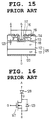
- FIG. 15 is a cross-sectional view illustrating the structure of a conventional n-channel UMOSFET (U-Shaped MOSFET).
- the n-channel UMOSFET has the same forward and reverse conduction characteristics as those of the n-channel DMOSFET illustrated in FIG. 12, and has the same electric characteristics and equivalent circuit illustrated in FIG. 13 and FIG. 14 respectively.
- the drain current I D is defined by the parasitic diode characteristics regardless of the gate-source voltage V GS with respect to the drain-source voltage V DS higher than the forward ON voltage (threshold) of the parasitic diode 123 (e.g., 1V or more).
- the current I D cannot be controlled by the bias voltage of the gate terminal with respect to the drain-source voltage V DS higher than the forward ON voltage of the parasitic diode 123 (e.g., 1V or more) and therefore, electric conduction can not always be prevented.
- V DS the drain-source voltage
- the parasitic diode 123 e.g. 1V or more
- a blocking diode 128 is connected in series to the drain terminal D as illustrated in FIG.
- FIG. 17 The forward electric characteristics illustrated in FIG. 17 are the electric characteristics illustrated in FIG. 13 but shifted to the right by the amount of the forward voltage drop V AD (e.g., 0.7V) of the blocking diode 128.
- V AD forward voltage drop
- a pair of circuits illustrated in FIG. 16 must be connected so as to be reverse parallel to each other as illustrated in FIG. 18. Therefore, in the circuit illustrated in FIG. 18, a problem exists that the number of parts and components, as well as the volume taken up by the device, are doubled. There is also a problem that due to the voltage drop at forward conduction, the forward voltage drop V AD (e.g., 0.7V) of the blocking diode 128 is added to the voltage drop of the MOSFET 127, resulting in increase in voltage loss.
- V AD e.g., 0.7V
- the semiconductor device that achieves the above object is a semiconductor device having a MOSFET structure which can control the current flowing therethrough by the voltage applied to a gate electrode.
- This semiconductor device comprises a semiconductor substrate having a low-resistance semiconductor layer of a first conductivity type and a high-resistance semiconductor layer of the first conductivity type formed on the low-resistance semiconductor layer; a body region of a second conductivity type formed on the semiconductor substrate; a source region of the first conductivity type formed within the body region and having a resistance lower than that of the high-resistance semiconductor layer; a source electrode contacting the source region; a gate electrode located on the surface of the body region with an insulating film disposed therebetween for forming a channel region at a surface of the body region between the high-resistance semiconductor layer and the source region; and a current controlling means connected between the body region and the source electrode for controlling a control current flowing from the source region to the semiconductor substrate via the channel region so as to predominate over a parasitic
- the electric potential of the body region to the source region is determined by connecting a current controlling means between the body region and the source region. Furthermore, by varying the electric potential of the gate electrode, a channel region is formed at the surface of the body region between the high-resistance semiconductor layer and the source region.
- the control current substantially predominates as the current flowing through the whole semiconductor device. Furthermore, as this control current flows through the channel region, the amperage thereof can be controlled by the voltage applied to the gate electrode.
- the amperage of the current flowing through the same device can be controlled for both forward and reverse biases according to the voltage applied to the gate electrode.
- the voltage loss does not increase. Therefore, a semiconductor device can be obtained which can control the amperage for both forward and reverse biases and does not increase the voltage loss without increasing (by minimizing) the number of parts and components and the volume of the device.
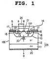
- FIG. 1 is a cross-sectional view illustrating an embodiment of the present invention used in an n-channel type DMOSFET 100, which is a power semiconductor device.
- n-type is used as the first conductivity type
- p-type is used as the second conductivity type.
- an n ⁇ silicon layer 12 high-resistance semiconductor layer
- an n+ silicon layer 11 low-resistance semiconductor layer
- these two silicon layers 11 and 12 compose a semiconductor substrate 25.
- a p-body region 13 Within the n ⁇ silicon layer 12 is formed a p-body region 13 (first semiconductor region).
- Within the p-body region 13 is formed an n+ source region 14 (second semiconductor region).
- a source electrode 191 electrically in contact only with the n+ source region 14 and a base electrode 21 electrically in contact only with the p-body region 13.
- the base electrode 21 is connected to a base terminal B.
- the base terminal B is connected to a source terminal S through a resistance 26.
- FIG. 2 is a graph illustrating characteristics between the drain current I D and the drain-source voltage V DS . The details of the electric characteristics when the transistor is ON in the forward conduction is illustrated in the first quadrant of FIG. 2. As the voltage V DS increases, the current I D increases and becomes saturated at a specific amperage. On the other hand, as the voltage gate-source V GS is increased, the saturation amperage rises simultaneously.
- the exciting current of the parasitic diode 23 can be restrained to a low, negligible value as compared with the exciting current of the MOSFET 27 (electronic current flowing through the channel region 18 into the n+ source region 14).
- the details of the electric properties when this semiconductor device is ON in a reverse conduction state are illustrated in the third quadrant of FIG. 2.
- the exciting characteristics of the parasitic diode 23 illustrated in the third quadrant of FIG. 13 are blocked by the resistance 26, and with respect to reverse conduction, the characteristics only of the MOSFET 27 appear as illustrated in the third quadrant of FIG. 2. Therefore, the semiconductor device can securely be turned ON and OFF by the gate-source voltage V GS .
- the increase in voltage drop as illustrated in the first quadrant of FIG. 17 does not occur in this embodiment. Therefore, in this embodiment, the current flow through the device can be controlled also with respect to the reverse bias, whereby AC signals can be controlled only by a single n-channel type DMOSFET.
- such a semiconductor device as illustrated in FIG. 1 is used to describe the basic composition.
- thousands of the unit cells illustrated in FIG. 1 are connected in parallel.
- it is preferable that a single resistance 26 is used per whole device or per any given block. It is a matter of course, however, that the resistance 26 can be used per unit cell. Also the resistance 26 can be formed within other regions on the semiconductor substrate or an external resistance can be connected.
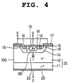
- FIG. 4 is a cross-sectional view illustrating an embodiment of a n-channel type DMOSFET 100 in which the resistance in the first embodiment is formed within a p-body region 13.
- n-channel type DMOSFET 100 on an n+ silicon layer 11 (low-resistance semiconductor layer) is formed an n ⁇ silicon layer 12 (high-resistance semiconductor layer), and these two layers 11 and 12 make up a semiconductor substrate 25.
- n ⁇ silicon layer 12 Within the n ⁇ silicon layer 12 is formed a p-body region 13 (first semiconductor region), and within the p-body region 13 are formed an n+ source region 14 (second semiconductor region) and a p ⁇ base region 15 (third semiconductor region).
- the case of forward conduction is the same as the case with the n-channel type DMOSFET illustrated in FIG. 1.
- a main voltage is applied in such a way that the drain terminal D can be high in electric potential and the source terminal S can be low in electric potential and a positive bias is applied to the gate terminal G, an inversion layer is formed within a channel region 18 and electronic current flows from n+ source region 14 through the channel region 18 into the n ⁇ silicon semiconductor layer 12, so that the n-channel type DMOSFET is turned to be in the ON state.
- the relational characteristics between the drain current I D and the drain-source voltage V DS are the same as those illustrated in the first quadrant of FIG. 2.
- the drain terminal D When a main voltage is applied in such a way that the drain terminal D is low in electric potential and the source terminal S is high in electric potential and a positive bias is applied to the gate terminal G, an inversion layer is formed within the channel region 18 and electronic current flows from the n ⁇ silicon layer 12 through the channel region 18 into the n+ source region 14, and therefore the n-channel type DMOSFET 100 is turned to be in the ON state.
- the main voltage is higher that a certain voltage (e.g., 0.7V)
- a parasitic diode 23 formed between the p-body region 13 and the n ⁇ silicon layer 12 operates.
- the concentration of impurities within the p ⁇ base region 15 is set to be very low, so that the resistance 261 is set to be very large. Therefore, the exciting current of the parasitic diode 23 can be restrained to be negligibly small as compared with the exciting current of the MOSFET 27 (electronic current flowing through the channel region 18 into the n+ source region 14).
- the details of the electric characteristics when the semiconductor device is ON with reverse conduction are illustrated in the third quadrant of FIG. 2 as in the first embodiment.
- the conduction characteristics of the parasitic diode 23 illustrated in the third quadrant in FIG. 2 are blocked by the resistance 261, and with respect to reverse conduction, the characteristics only of the MOSFET 27 appear as illustrated in the third quadrant of FIG. 2. That is, the drain current I D flowing through the device can securely be turned ON and OFF by the gate-source voltage V GS . In addition, increases in the voltage drop, as seen in the first quadrant of FIG. 17, do not occur. Therefore, also in this embodiment, the current flowing through the device can be controlled with respect to reverse bias, whereby AC signals can be controlled only by a single n-channel DMOSFET.
- FIG. 5 is a cross-sectional view of an n-channel type UMOSFET 101 to which a power semiconductor device according to the present invention is applied.
- a p-body region 13 on the n ⁇ silicon layer 12 is formed a p-body region 13, and within the p-body region 13 is formed an n+ source region 14.
- a trench of a gate oxide film (insulating film) 16 is formed extending from the top side of a substrate 25 to the n ⁇ silicon layer 12, and through the gate oxide film (insulating film) 16 is formed a gate electrode 17.
- a source electrode 191 electrically in contact only with the n+ source region 14 and a base electrode 21 electrically in contact only with the p-body region 13.
- the base electrode 21 is connected to a base terminal B, and the base terminal B is connected to a source terminal S through a resistance 26.
- the equivalent circuit of this embodiment of the n-channel type UMOSFET 101 is the same circuit as that of the n-channel type DMOSFET of FIG. 1, with the circuit illustrated in FIG. 3.
- the electric characteristics thereof are the same as those illustrated in FIG. 2. Accordingly, also in this embodiment, the conduction characteristics of a parasitic diode 23 are blocked by the resistance 26 connected to the outside as in the first embodiment.
- the drain current flowing through the device can be controlled by the gate voltage also with respect to a reverse bias without increasing the current loss. Therefore, also in this embodiment, an n-channel type UMOSFET which can control AC signals with the minimum number of parts and components can be obtained.
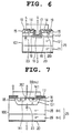
- FIG. 6 is a cross-sectional view illustrating an n-channel type UMOSFET 101 in which the resistance used in the third embodiment is formed within a p-body region 13.
- a p-body region 13 on an n ⁇ silicon layer 12 is formed a p-body region 13, and within the p-body region 13 are formed an n+ source region 14 and a p ⁇ base region 15.
- a trench of a gate oxide film (insulating film) 16 is formed extending from the top side of the substrate to the n ⁇ silicon layer 12, and through the gate oxide film (insulating film) 16 is formed a gate electrode 17.
- the equivalent circuit of this embodiment of the n-channel type UMOSFET 101 is the same as the circuit shown in FIG. 3, which is the circuit for the n-channel type DMOSFET illustrated in FIG. 1.
- the electric characteristics thereof are the same as those illustrated in FIG. 2. Accordingly, also in this embodiment, the conduction characteristics of a parasitic diode 23 are blocked by the resistance 261 formed in the p ⁇ base region 15 as in the second embodiment.
- the drain current flowing through the device can be controlled by the gate voltage also with respect to a reverse bias without increasing the current loss. Therefore, also in this embodiment, an n-channel type UMOSFET which can control AC signals without increasing the number of parts and components can be obtained.
- FIG. 7 is a cross-sectional view illustrating an n-channel type DMOSFET 100 which is the fifth embodiment of a semiconductor device according to the present invention.
- a semiconductor substrate 25, a p-body region 131 and an n+ source region 141 are hexagonal system SiC single crystals.
- the azimuth of the surface of the semiconductor substrate 25 is the (0001) plane, and on this plane is formed a p-body region 131 by epitaxial growth.
- a Ni source electrode 30 electrically in contact with and common to the p-body region 131 and the n+ source region 141 is formed using nickel ("Ni").
- the contact resistance of the part where the p-body region 131 is in contact with the Ni source electrode 30 is set to be larger than that of the part where the n+ source region 141 is in contact with the Ni source electrode 30, and a resistance 262 is substantially formed in the part where the p-body region 131 is in contact with the Ni source electrode 30. Accordingly, the equivalent circuit of the n-channel type DMOSFET 100 illustrated in FIG. 7 is the same as that illustrated in FIG. 3 due to the resistance 262 in the part where the p-body region 131 is in contact with the Ni source electrode 30.
- the conduction characteristics of the parasitic diode 23 illustrated in the third quadrant of FIG. 2 are blocked by the resistance 262, and with respect to reverse conduction characteristics illustrated in the third quadrant of FIG. 2, the characteristics only of the MOSFET 27 appear as in the first embodiment.
- the drain current flowing through the device can be controlled by the gate voltage without increasing the current loss.
- the gate-source voltage V GS of an n-channel type DMOSFET but also, as there is no need for an external resistance, the number of parts and components can be reduced.
- the time required for design is not more than the time required for conventional MOSFETs.
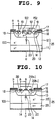
- FIG. 8 is a cross-sectional view illustrating the sixth embodiment of an n-channel type UMOSFET 101 according to the present invention.
- a semiconductor substrate 25, a p-body region 131 and an n+ source region 141 are hexagonal system SiC single crystals as in the fifth embodiment.
- the azimuth of the surface of the semiconductor substrate 25 is on the (0001) plane, and on this plane is formed a p-body region 131 by epitaxial growth.
- a trench of a gate oxide film (insulating film) 16 is formed extending from the top side of the substrate to the n ⁇ SiC layer 28, and through the gate oxide film (insulating film) 16 is formed a gate electrode 17.
- a Ni source electrode 30 electrically in contact with and common to the p-body region 131 and the n+ source region 141 is formed using nickel ("Ni").
- Ni nickel
- the contact resistance of the part where the p-body region 131 is in contact with the Ni source electrode 30 is set to be larger than that of the part where the n+ source region 141 is in contact with the Ni source electrode 30, and a resistance 262 is substantially formed within the part where the p-body region 131 is in contact with the Ni source electrode 30.
- the equivalent circuit of the n-channel type UMOSFET illustrated in FIG. 8 is substantially the same as that illustrated in FIG. 3 due to the resistance 262 within the part where the p-body region 131 in contact with the Ni source electrode 30, and the electric characteristics thereof are the same as those illustrated in FIG. 2.
- the conducting characteristics of the parasitic diode 23 illustrated in the third quadrant of FIG. 2 are blocked by the resistance 262, and with respect to reverse conducting characteristics illustrated in the third quadrant of FIG. 2, the characteristics only of the MOSFET 27 appear as in the first embodiment.
- the number of parts and components can be reduced.
- the structure except for the semiconductor material is the same as that of conventional MOSFETs, increases in the time required for design, for example, can be avoided.
- the source electrode is divided into two source electrodes.
- One is a source electrode electrically in contact only with the n+ source region
- the other is a base electrode electrically in contact only with the p-body region.
- the base electrode is connected to the source terminal S through a resistance, or otherwise the source electrode is provided so that the resistance of the part where the p-body area is in contact with the source electrode is set to be larger than that of the part where the n+ source region is in contact with the source electrode to have a resistance substantially formed within the part where the p-body region contacts the source electrode.
- the conducting characteristics of the parasitic diode are blocked by the resistance, and with respect to the reverse conducting characteristics of the semiconductor device, the characteristics only of the MOSFET appear.
- the semiconductor device can securely be turned ON and OFF by the gate-source voltage even if the semiconductor device is reverse biased.
- AC signals can be controlled only by a single semiconductor device.
- increase in voltage drop in forward conduction characteristics does not occur.
- the resistance used in the first and third embodiments may either be connected to the outside or buried inside as illustrated in FIG. 9 (in this case, although a resistance layer is formed within the p-body region, the resistance layer may be formed within any other separate region on the semiconductor substrate), for example.
- the semiconductor device when the semiconductor device is actually used as a power semiconductor device, thousands of the unit cells illustrated are connected. Therefore, when the resistance is connected to the outside, the resistance may be connected for each unit cell. However, it is preferable that one resistance should be used for the whole device or in any block unit for higher productivity.
- the base layer 15 is set to be p ⁇ type.
- the base layer 15 may be set to be a compensation type (intrinsic type) or a non-doped layer to further increase the resistance therein. If the base layer 15 is set to be an n type or n ⁇ type in this structure, an energy barrier is produced between the base layer 15 and the p-body region 13. Therefore, when the base layer 15 of FIG. 4 is set to be an n type or n ⁇ type, as shown by n ⁇ base layer 152 in FIG. 9, it is preferable that an electrode 192 should be included within the structure as illustrated in FIG. 9, for example.
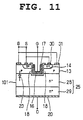
- the source electrode 30 may be divided into a source electrode 30 and a base electrode 31 as illustrated in FIGs. 10 and 11.
- nickel is used as the material of the electrode, which provides high contact resistance to p ⁇ type SiC and low contact resistance to n+ SiC.
- any material, such as aluminum may be used as long as the material has the characteristics described above.
- the structure of the trench described above is not limited to that illustrated in the figure, and may be U-shaped or V-shaped, for example.
- the present invention is not limited to power MOSFETs, but may be applied to any other type of vertical MOSFET.
- a plurality of positions are disclosed as parts at which the resistance is provided, including the inside of the semiconductor substrate, outside thereof, and the electrode contacting part.
- various modifications are possible for blocking the conducting characteristics of a parasitic diode, and these modifications are included within the scope of the claims.
Landscapes
- Engineering & Computer Science (AREA)
- Microelectronics & Electronic Packaging (AREA)
- Power Engineering (AREA)
- Physics & Mathematics (AREA)
- Ceramic Engineering (AREA)
- Condensed Matter Physics & Semiconductors (AREA)
- General Physics & Mathematics (AREA)
- Computer Hardware Design (AREA)
- Metal-Oxide And Bipolar Metal-Oxide Semiconductor Integrated Circuits (AREA)
- Insulated Gate Type Field-Effect Transistor (AREA)
Applications Claiming Priority (2)
| Application Number | Priority Date | Filing Date | Title |
|---|---|---|---|
| JP283240/93 | 1993-11-12 | ||
| JP28324093A JP3334290B2 (ja) | 1993-11-12 | 1993-11-12 | 半導体装置 |
Publications (2)
| Publication Number | Publication Date |
|---|---|
| EP0656661A1 true EP0656661A1 (fr) | 1995-06-07 |
| EP0656661B1 EP0656661B1 (fr) | 1999-03-10 |
Family
ID=17662910
Family Applications (1)
| Application Number | Title | Priority Date | Filing Date |
|---|---|---|---|
| EP94117694A Expired - Lifetime EP0656661B1 (fr) | 1993-11-12 | 1994-11-09 | DMOSFET avec une résistance pour améliorer la conduction en polarisation inverse |
Country Status (4)
| Country | Link |
|---|---|
| US (1) | US5696396A (fr) |
| EP (1) | EP0656661B1 (fr) |
| JP (1) | JP3334290B2 (fr) |
| DE (1) | DE69416950T2 (fr) |
Cited By (17)
| Publication number | Priority date | Publication date | Assignee | Title |
|---|---|---|---|---|
| FR2750799A1 (fr) * | 1996-06-11 | 1998-01-09 | Mitsubishi Electric Corp | Dispositif a semiconducteurs empechant le deverrouillage et procede de fabrication de ce dispositif |
| US5708352A (en) * | 1993-12-07 | 1998-01-13 | Nippondenso Co., Ltd. | A.C. Generator for vehicles |
| US5719760A (en) * | 1995-06-06 | 1998-02-17 | Nippondenso Co., Ltd. | Direct-mounted vehicle generator using low heat producing SiC rectifiers |
| EP0746042A3 (fr) * | 1995-06-02 | 1998-04-01 | SILICONIX Incorporated | MOSFET de puissance avec tranchée bloquant bidirectionnel |
| US5744826A (en) * | 1996-01-23 | 1998-04-28 | Denso Corporation | Silicon carbide semiconductor device and process for its production |
| FR2764119A1 (fr) * | 1997-05-27 | 1998-12-04 | Mitsubishi Electric Corp | Transistor bipolaire a grille isolee et procede pour sa fabrication |
| EP0921619A2 (fr) * | 1997-12-08 | 1999-06-09 | Nec Corporation | Circuit d'alimentation pour circuit intégré semi-conducteur |
| US5976936A (en) * | 1995-09-06 | 1999-11-02 | Denso Corporation | Silicon carbide semiconductor device |
| US6096608A (en) * | 1997-06-30 | 2000-08-01 | Siliconix Incorporated | Bidirectional trench gated power mosfet with submerged body bus extending underneath gate trench |
| US6133587A (en) * | 1996-01-23 | 2000-10-17 | Denso Corporation | Silicon carbide semiconductor device and process for manufacturing same |
| US6262439B1 (en) | 1997-11-28 | 2001-07-17 | Denso Corporation | Silicon carbide semiconductor device |
| DE10001871A1 (de) * | 2000-01-18 | 2001-08-02 | Infineon Technologies Ag | Verfahren zur Herstellung eines steuerbaren Halbleiterschalt-elements und steuerbares Halbleiterschaltelement |
| US6512251B2 (en) | 2000-05-30 | 2003-01-28 | Infineon Technologies Ag | Semiconductor switching element that blocks in both directions |
| US6573534B1 (en) | 1995-09-06 | 2003-06-03 | Denso Corporation | Silicon carbide semiconductor device |
| US6686625B2 (en) | 2000-12-05 | 2004-02-03 | Infineon Technologies Ag | Field effect-controllable semiconductor component with two-directional blocking, and a method of producing the semiconductor component |
| WO2008069145A1 (fr) | 2006-12-04 | 2008-06-12 | Sanken Electric Co., Ltd. | Tec à grille isolante et son procédé de fabrication |
| EP2302683A1 (fr) * | 2008-06-02 | 2011-03-30 | Sanken Electric Co., Ltd. | Dispositif à semi-conducteur à effet de champ et son procédé de fabrication |
Families Citing this family (44)
| Publication number | Priority date | Publication date | Assignee | Title |
|---|---|---|---|---|
| US5998837A (en) * | 1995-06-02 | 1999-12-07 | Siliconix Incorporated | Trench-gated power MOSFET with protective diode having adjustable breakdown voltage |
| US6140678A (en) * | 1995-06-02 | 2000-10-31 | Siliconix Incorporated | Trench-gated power MOSFET with protective diode |
| US6049108A (en) * | 1995-06-02 | 2000-04-11 | Siliconix Incorporated | Trench-gated MOSFET with bidirectional voltage clamping |
| JP2988871B2 (ja) * | 1995-06-02 | 1999-12-13 | シリコニックス・インコーポレイテッド | トレンチゲートパワーmosfet |
| JPH1167786A (ja) * | 1997-08-25 | 1999-03-09 | Mitsubishi Electric Corp | 半導体装置及びその製造方法 |
| US6002277A (en) * | 1998-04-06 | 1999-12-14 | Intersil Corporation | Sample-and-hold circuit having reduced parasitic diode effects and related methods |
| US6016067A (en) * | 1998-04-06 | 2000-01-18 | Intersil Corporation | Sample-and-hold circuit having reduced amplifier offset effects and related methods |
| US6069502A (en) * | 1998-04-06 | 2000-05-30 | Intersil Corporation | Sample-and-hold circuit having reduced subthreshold conduction effects and related methods |
| US6117602A (en) * | 1999-01-19 | 2000-09-12 | Xerox Corporation | Electrostatic printing method and apparatus having enhanced image resolution characteristics |
| US6191447B1 (en) | 1999-05-28 | 2001-02-20 | Micro-Ohm Corporation | Power semiconductor devices that utilize tapered trench-based insulating regions to improve electric field profiles in highly doped drift region mesas and methods of forming same |
| US6809348B1 (en) * | 1999-10-08 | 2004-10-26 | Denso Corporation | Semiconductor device and method for manufacturing the same |
| WO2001031786A1 (fr) * | 1999-10-27 | 2001-05-03 | Fuji Electric Co., Ltd. | Transistor unipolaire et convertisseur de puissance equipe de celui-ci |
| JP2001145369A (ja) * | 1999-11-18 | 2001-05-25 | Fuji Electric Co Ltd | インバータ |
| IT1311309B1 (it) * | 1999-12-10 | 2002-03-12 | St Microelectronics Srl | Resistore verticale integrato ad alta tensione e relativo processo difabbricazione. |
| DE10001869B4 (de) * | 2000-01-18 | 2006-10-26 | Infineon Technologies Ag | In beiden Richtungen sperrendes steuerbares Halbleiterschaltelement |
| DE10024518B4 (de) * | 2000-05-18 | 2006-12-07 | Infineon Technologies Ag | Integriertes Halbleiterschaltelement und Herstellungsverfahren |
| US6534828B1 (en) * | 2000-09-19 | 2003-03-18 | Fairchild Semiconductor Corporation | Integrated circuit device including a deep well region and associated methods |
| US6504208B2 (en) | 2001-02-27 | 2003-01-07 | International Business Machines Corporation | Power MOSFET device, structures employing the same and methods of fabrication |
| DE10117360B4 (de) * | 2001-04-06 | 2006-03-16 | Infineon Technologies Ag | Halbbrückenschaltung |
| DE10217610B4 (de) * | 2002-04-19 | 2005-11-03 | Infineon Technologies Ag | Metall-Halbleiter-Kontakt, Halbleiterbauelement, integrierte Schaltungsanordnung und Verfahren |
| US7164155B2 (en) * | 2002-05-15 | 2007-01-16 | Semiconductor Energy Laboratory Co., Ltd. | Light emitting device |
| JP2004055803A (ja) * | 2002-07-19 | 2004-02-19 | Renesas Technology Corp | 半導体装置 |
| US6885065B2 (en) * | 2002-11-20 | 2005-04-26 | Freescale Semiconductor, Inc. | Ferromagnetic semiconductor structure and method for forming the same |
| EP1519419B1 (fr) | 2003-09-24 | 2018-02-21 | Nissan Motor Co., Ltd. | Dispositif semiconducteur et procédé pour sa fabrication |
| JP4852876B2 (ja) * | 2005-04-27 | 2012-01-11 | トヨタ自動車株式会社 | 半導体装置 |
| DE102006031538A1 (de) * | 2006-07-07 | 2008-01-17 | Infineon Technologies Ag | Integrierte Halbleiteranordnung und Herstellverfahren dafür |
| US9437729B2 (en) * | 2007-01-08 | 2016-09-06 | Vishay-Siliconix | High-density power MOSFET with planarized metalization |
| US9947770B2 (en) | 2007-04-03 | 2018-04-17 | Vishay-Siliconix | Self-aligned trench MOSFET and method of manufacture |
| US9484451B2 (en) | 2007-10-05 | 2016-11-01 | Vishay-Siliconix | MOSFET active area and edge termination area charge balance |
| US7915944B2 (en) * | 2009-04-27 | 2011-03-29 | General Electric Company | Gate drive circuitry for non-isolated gate semiconductor devices |
| WO2010125819A1 (fr) | 2009-04-30 | 2010-11-04 | パナソニック株式会社 | Élément semi-conducteur, dispositif à semi-conducteurs et convertisseur de puissance |
| US8283973B2 (en) | 2009-08-19 | 2012-10-09 | Panasonic Corporation | Semiconductor element, semiconductor device, and electric power converter |
| US9443974B2 (en) | 2009-08-27 | 2016-09-13 | Vishay-Siliconix | Super junction trench power MOSFET device fabrication |
| US9431530B2 (en) * | 2009-10-20 | 2016-08-30 | Vishay-Siliconix | Super-high density trench MOSFET |
| CN102725849B (zh) * | 2010-01-27 | 2015-09-09 | 住友电气工业株式会社 | 碳化硅半导体器件及其制造方法 |
| EP2482315B1 (fr) * | 2010-10-29 | 2015-08-12 | Panasonic Intellectual Property Management Co., Ltd. | Element semi-conducteur |
| US9842911B2 (en) | 2012-05-30 | 2017-12-12 | Vishay-Siliconix | Adaptive charge balanced edge termination |
| US9722041B2 (en) | 2012-09-19 | 2017-08-01 | Vishay-Siliconix | Breakdown voltage blocking device |
| US9887259B2 (en) | 2014-06-23 | 2018-02-06 | Vishay-Siliconix | Modulated super junction power MOSFET devices |
| CN107078161A (zh) | 2014-08-19 | 2017-08-18 | 维西埃-硅化物公司 | 电子电路 |
| EP3183754A4 (fr) | 2014-08-19 | 2018-05-02 | Vishay-Siliconix | Transistor à effet de champ à semi-conducteur d'oxyde de métal à super jonction |
| JP6515842B2 (ja) * | 2016-03-10 | 2019-05-22 | 豊田合成株式会社 | 半導体装置 |
| DE102016109235B4 (de) * | 2016-05-19 | 2019-02-14 | Infineon Technologies Ag | Elektrische baugruppe, die eine rückwärts leitende schaltvorrichtung und eine gleichrichtende vorrichtung enthält |
| CN114068675A (zh) * | 2021-11-16 | 2022-02-18 | 大连海事大学 | 一种双极分裂栅增强型功率晶体管 |
Citations (5)
| Publication number | Priority date | Publication date | Assignee | Title |
|---|---|---|---|---|
| JPS5974674A (ja) * | 1982-10-22 | 1984-04-27 | Hitachi Ltd | 絶縁ゲ−ト半導体装置とその製造法 |
| JPS6180858A (ja) * | 1984-09-28 | 1986-04-24 | Hitachi Ltd | パワ−mosfet |
| DE3824836A1 (de) * | 1987-07-21 | 1989-02-02 | Nippon Denso Co | Isolierschicht-bipolartransistor |
| JPH01135072A (ja) * | 1987-11-20 | 1989-05-26 | Nissan Motor Co Ltd | 縦形mosfet |
| EP0399530A1 (fr) * | 1989-05-23 | 1990-11-28 | Kabushiki Kaisha Toshiba | Dispositif semi-conducteur ayant une couche intermédiaire entre une électrode et une électrode de connexion |
Family Cites Families (12)
| Publication number | Priority date | Publication date | Assignee | Title |
|---|---|---|---|---|
| US4837606A (en) * | 1984-02-22 | 1989-06-06 | General Electric Company | Vertical MOSFET with reduced bipolar effects |
| JPS6212167A (ja) * | 1985-07-10 | 1987-01-21 | Tdk Corp | 溝部を有する縦形半導体装置の製造方法 |
| JPH01134974A (ja) * | 1987-11-20 | 1989-05-26 | Hitachi Ltd | 縦型mosfet |
| JPH0783118B2 (ja) * | 1988-06-08 | 1995-09-06 | 三菱電機株式会社 | 半導体装置およびその製造方法 |
| JP2542448B2 (ja) * | 1990-05-24 | 1996-10-09 | シャープ株式会社 | 電界効果トランジスタおよびその製造方法 |
| JP2917532B2 (ja) * | 1991-01-24 | 1999-07-12 | 富士電機株式会社 | 電界効果トランジスタ |
| JP3321189B2 (ja) * | 1991-10-04 | 2002-09-03 | 株式会社東芝 | 電力用半導体素子 |
| US5233215A (en) * | 1992-06-08 | 1993-08-03 | North Carolina State University At Raleigh | Silicon carbide power MOSFET with floating field ring and floating field plate |
| US5389799A (en) * | 1992-06-12 | 1995-02-14 | Kabushiki Kaisha Toshiba | Semiconductor device |
| US5506421A (en) * | 1992-11-24 | 1996-04-09 | Cree Research, Inc. | Power MOSFET in silicon carbide |
| US5399515A (en) * | 1993-07-12 | 1995-03-21 | Motorola, Inc. | Method of fabricating a silicon carbide vertical MOSFET and device |
| US5323040A (en) * | 1993-09-27 | 1994-06-21 | North Carolina State University At Raleigh | Silicon carbide field effect device |
-
1993
- 1993-11-12 JP JP28324093A patent/JP3334290B2/ja not_active Expired - Lifetime
-
1994
- 1994-11-09 DE DE69416950T patent/DE69416950T2/de not_active Expired - Lifetime
- 1994-11-09 EP EP94117694A patent/EP0656661B1/fr not_active Expired - Lifetime
-
1996
- 1996-10-21 US US08/734,132 patent/US5696396A/en not_active Expired - Lifetime
Patent Citations (5)
| Publication number | Priority date | Publication date | Assignee | Title |
|---|---|---|---|---|
| JPS5974674A (ja) * | 1982-10-22 | 1984-04-27 | Hitachi Ltd | 絶縁ゲ−ト半導体装置とその製造法 |
| JPS6180858A (ja) * | 1984-09-28 | 1986-04-24 | Hitachi Ltd | パワ−mosfet |
| DE3824836A1 (de) * | 1987-07-21 | 1989-02-02 | Nippon Denso Co | Isolierschicht-bipolartransistor |
| JPH01135072A (ja) * | 1987-11-20 | 1989-05-26 | Nissan Motor Co Ltd | 縦形mosfet |
| EP0399530A1 (fr) * | 1989-05-23 | 1990-11-28 | Kabushiki Kaisha Toshiba | Dispositif semi-conducteur ayant une couche intermédiaire entre une électrode et une électrode de connexion |
Non-Patent Citations (4)
| Title |
|---|
| JOHN W. PALMOUR ET AL: "6H-Silicon Carbide Power Devices for Aerospace Applications", PROCEEDINGS OF THE 28TH INTERSOCIETY ENERGY CONVERSION ENGINEERING CONFERENCE VOLUME 1, AUGUST 8-13, 1993 ATLANTA, GEORGIA, pages 1249 - 1254 * |
| PATENT ABSTRACTS OF JAPAN vol. 10, no. 251 (E - 432) 28 August 1986 (1986-08-28) * |
| PATENT ABSTRACTS OF JAPAN vol. 13, no. 386 (E - 812) 25 August 1989 (1989-08-25) * |
| PATENT ABSTRACTS OF JAPAN vol. 8, no. 181 (E - 261) 21 August 1984 (1984-08-21) * |
Cited By (26)
| Publication number | Priority date | Publication date | Assignee | Title |
|---|---|---|---|---|
| US5708352A (en) * | 1993-12-07 | 1998-01-13 | Nippondenso Co., Ltd. | A.C. Generator for vehicles |
| EP0746042A3 (fr) * | 1995-06-02 | 1998-04-01 | SILICONIX Incorporated | MOSFET de puissance avec tranchée bloquant bidirectionnel |
| US5877538A (en) * | 1995-06-02 | 1999-03-02 | Silixonix Incorporated | Bidirectional trench gated power MOSFET with submerged body bus extending underneath gate trench |
| US5719760A (en) * | 1995-06-06 | 1998-02-17 | Nippondenso Co., Ltd. | Direct-mounted vehicle generator using low heat producing SiC rectifiers |
| US6573534B1 (en) | 1995-09-06 | 2003-06-03 | Denso Corporation | Silicon carbide semiconductor device |
| US5976936A (en) * | 1995-09-06 | 1999-11-02 | Denso Corporation | Silicon carbide semiconductor device |
| US6020600A (en) * | 1995-09-06 | 2000-02-01 | Nippondenso Co., Ltd. | Silicon carbide semiconductor device with trench |
| US5744826A (en) * | 1996-01-23 | 1998-04-28 | Denso Corporation | Silicon carbide semiconductor device and process for its production |
| US6133587A (en) * | 1996-01-23 | 2000-10-17 | Denso Corporation | Silicon carbide semiconductor device and process for manufacturing same |
| FR2750799A1 (fr) * | 1996-06-11 | 1998-01-09 | Mitsubishi Electric Corp | Dispositif a semiconducteurs empechant le deverrouillage et procede de fabrication de ce dispositif |
| FR2764119A1 (fr) * | 1997-05-27 | 1998-12-04 | Mitsubishi Electric Corp | Transistor bipolaire a grille isolee et procede pour sa fabrication |
| US5925899A (en) * | 1997-05-27 | 1999-07-20 | Mitsubishi Denki Kabushiki Kaisha | Vertical type insulated gate bipolar transistor having a planar gate structure |
| US6096608A (en) * | 1997-06-30 | 2000-08-01 | Siliconix Incorporated | Bidirectional trench gated power mosfet with submerged body bus extending underneath gate trench |
| US6262439B1 (en) | 1997-11-28 | 2001-07-17 | Denso Corporation | Silicon carbide semiconductor device |
| EP0921619A3 (fr) * | 1997-12-08 | 1999-12-22 | Nec Corporation | Circuit d'alimentation pour circuit intégré semi-conducteur |
| EP0921619A2 (fr) * | 1997-12-08 | 1999-06-09 | Nec Corporation | Circuit d'alimentation pour circuit intégré semi-conducteur |
| DE10001871A1 (de) * | 2000-01-18 | 2001-08-02 | Infineon Technologies Ag | Verfahren zur Herstellung eines steuerbaren Halbleiterschalt-elements und steuerbares Halbleiterschaltelement |
| US6512251B2 (en) | 2000-05-30 | 2003-01-28 | Infineon Technologies Ag | Semiconductor switching element that blocks in both directions |
| US6686625B2 (en) | 2000-12-05 | 2004-02-03 | Infineon Technologies Ag | Field effect-controllable semiconductor component with two-directional blocking, and a method of producing the semiconductor component |
| WO2008069145A1 (fr) | 2006-12-04 | 2008-06-12 | Sanken Electric Co., Ltd. | Tec à grille isolante et son procédé de fabrication |
| EP2093802A1 (fr) * | 2006-12-04 | 2009-08-26 | Sanken Electric Co., Ltd. | Tec à grille isolante et son procédé de fabrication |
| EP2093802A4 (fr) * | 2006-12-04 | 2011-03-02 | Sanken Electric Co Ltd | Tec à grille isolante et son procédé de fabrication |
| EP2302683A1 (fr) * | 2008-06-02 | 2011-03-30 | Sanken Electric Co., Ltd. | Dispositif à semi-conducteur à effet de champ et son procédé de fabrication |
| EP2302683A4 (fr) * | 2008-06-02 | 2011-07-27 | Sanken Electric Co Ltd | Dispositif à semi-conducteur à effet de champ et son procédé de fabrication |
| US8334563B2 (en) | 2008-06-02 | 2012-12-18 | Sanken Electric Co., Ltd. | Field-effect semiconductor device and method of producing the same |
| CN102047429B (zh) * | 2008-06-02 | 2013-05-08 | 三垦电气株式会社 | 场效应半导体装置及其制造方法 |
Also Published As
| Publication number | Publication date |
|---|---|
| DE69416950T2 (de) | 1999-11-11 |
| US5696396A (en) | 1997-12-09 |
| JP3334290B2 (ja) | 2002-10-15 |
| JPH07142722A (ja) | 1995-06-02 |
| DE69416950D1 (de) | 1999-04-15 |
| EP0656661B1 (fr) | 1999-03-10 |
Similar Documents
| Publication | Publication Date | Title |
|---|---|---|
| US5696396A (en) | Semiconductor device including vertical MOSFET structure with suppressed parasitic diode operation | |
| US11024731B2 (en) | Power module for supporting high current densities | |
| US8598620B2 (en) | MOSFET with integrated field effect rectifier | |
| US4656493A (en) | Bidirectional, high-speed power MOSFET devices with deep level recombination centers in base region | |
| US5710455A (en) | Lateral MOSFET with modified field plates and damage areas | |
| US9142662B2 (en) | Field effect transistor devices with low source resistance | |
| US11444155B2 (en) | Silicon carbide semiconductor device | |
| US20050224838A1 (en) | Semiconductor device with heterojunction | |
| US20090014719A1 (en) | Semiconductor device with large blocking voltage | |
| KR100922914B1 (ko) | 절연 기판 상에 형성된 전계 효과 트랜지스터 | |
| KR100381845B1 (ko) | 트렌치-게이트형파워mosfet | |
| US11522058B2 (en) | Semiconductor device with field plate electrode | |
| EP0697739A1 (fr) | Structure intégrée d'un dispositif de puissance à basse tension de saturation | |
| JP2009065026A (ja) | 電気回路のスイッチング装置 | |
| SE513284C3 (sv) | Halvledarkomponent med linjär ström-till-spänningskarakteristik | |
| US9029945B2 (en) | Field effect transistor devices with low source resistance | |
| JP2590863B2 (ja) | 導電変調型mosfet | |
| EP4169076A1 (fr) | Dispositifs d'alimentation dotés d'une structure de grille hybride | |
| US5360983A (en) | Insulated gate bipolar transistor having a specific buffer layer resistance | |
| EP0108945B1 (fr) | Dispositifs semi-conducteurs à haute tension à résistance de conductivité réduite | |
| GB2181890A (en) | Semiconductor power device | |
| WO2009134812A1 (fr) | Mosfet à redresseur à effet de champ intégré | |
| JPH01276769A (ja) | 絶縁ゲート型半導体装置 | |
| KR20200003593A (ko) | 반도체장치 | |
| JPH01169970A (ja) | 半導体装置 |
Legal Events
| Date | Code | Title | Description |
|---|---|---|---|
| PUAI | Public reference made under article 153(3) epc to a published international application that has entered the european phase |
Free format text: ORIGINAL CODE: 0009012 |
|
| AK | Designated contracting states |
Kind code of ref document: A1 Designated state(s): DE FR GB |
|
| 17P | Request for examination filed |
Effective date: 19950613 |
|
| 17Q | First examination report despatched |
Effective date: 19960821 |
|
| RAP1 | Party data changed (applicant data changed or rights of an application transferred) |
Owner name: DENSO CORPORATION |
|
| GRAG | Despatch of communication of intention to grant |
Free format text: ORIGINAL CODE: EPIDOS AGRA |
|
| GRAG | Despatch of communication of intention to grant |
Free format text: ORIGINAL CODE: EPIDOS AGRA |
|
| GRAH | Despatch of communication of intention to grant a patent |
Free format text: ORIGINAL CODE: EPIDOS IGRA |
|
| GRAH | Despatch of communication of intention to grant a patent |
Free format text: ORIGINAL CODE: EPIDOS IGRA |
|
| GRAA | (expected) grant |
Free format text: ORIGINAL CODE: 0009210 |
|
| AK | Designated contracting states |
Kind code of ref document: B1 Designated state(s): DE FR GB |
|
| REF | Corresponds to: |
Ref document number: 69416950 Country of ref document: DE Date of ref document: 19990415 |
|
| ET | Fr: translation filed | ||
| PLBE | No opposition filed within time limit |
Free format text: ORIGINAL CODE: 0009261 |
|
| STAA | Information on the status of an ep patent application or granted ep patent |
Free format text: STATUS: NO OPPOSITION FILED WITHIN TIME LIMIT |
|
| 26N | No opposition filed | ||
| REG | Reference to a national code |
Ref country code: GB Ref legal event code: 746 Effective date: 20000607 |
|
| REG | Reference to a national code |
Ref country code: GB Ref legal event code: IF02 |
|
| PGFP | Annual fee paid to national office [announced via postgrant information from national office to epo] |
Ref country code: GB Payment date: 20131120 Year of fee payment: 20 Ref country code: FR Payment date: 20131120 Year of fee payment: 20 Ref country code: DE Payment date: 20131121 Year of fee payment: 20 |
|
| REG | Reference to a national code |
Ref country code: DE Ref legal event code: R071 Ref document number: 69416950 Country of ref document: DE |
|
| REG | Reference to a national code |
Ref country code: GB Ref legal event code: PE20 Expiry date: 20141108 |
|
| PG25 | Lapsed in a contracting state [announced via postgrant information from national office to epo] |
Ref country code: GB Free format text: LAPSE BECAUSE OF EXPIRATION OF PROTECTION Effective date: 20141108 |