EP0633094B1 - Multi-stage automatic press and assembly machine - Google Patents
Multi-stage automatic press and assembly machine Download PDFInfo
- Publication number
- EP0633094B1 EP0633094B1 EP94109502A EP94109502A EP0633094B1 EP 0633094 B1 EP0633094 B1 EP 0633094B1 EP 94109502 A EP94109502 A EP 94109502A EP 94109502 A EP94109502 A EP 94109502A EP 0633094 B1 EP0633094 B1 EP 0633094B1
- Authority
- EP
- European Patent Office
- Prior art keywords
- cylinder
- work
- gripping
- press
- circuit
- Prior art date
- Legal status (The legal status is an assumption and is not a legal conclusion. Google has not performed a legal analysis and makes no representation as to the accuracy of the status listed.)
- Expired - Lifetime
Links
Images


Classifications
-
- B—PERFORMING OPERATIONS; TRANSPORTING
- B23—MACHINE TOOLS; METAL-WORKING NOT OTHERWISE PROVIDED FOR
- B23P—METAL-WORKING NOT OTHERWISE PROVIDED FOR; COMBINED OPERATIONS; UNIVERSAL MACHINE TOOLS
- B23P19/00—Machines for simply fitting together or separating metal parts or objects, or metal and non-metal parts, whether or not involving some deformation; Tools or devices therefor so far as not provided for in other classes
- B23P19/001—Article feeders for assembling machines
- B23P19/007—Picking-up and placing mechanisms
-
- B—PERFORMING OPERATIONS; TRANSPORTING
- B21—MECHANICAL METAL-WORKING WITHOUT ESSENTIALLY REMOVING MATERIAL; PUNCHING METAL
- B21K—MAKING FORGED OR PRESSED METAL PRODUCTS, e.g. HORSE-SHOES, RIVETS, BOLTS OR WHEELS
- B21K27/00—Handling devices, e.g. for feeding, aligning, discharging, Cutting-off means; Arrangement thereof
- B21K27/02—Feeding devices for rods, wire, or strips
- B21K27/04—Feeding devices for rods, wire, or strips allowing successive working steps
-
- B—PERFORMING OPERATIONS; TRANSPORTING
- B23—MACHINE TOOLS; METAL-WORKING NOT OTHERWISE PROVIDED FOR
- B23P—METAL-WORKING NOT OTHERWISE PROVIDED FOR; COMBINED OPERATIONS; UNIVERSAL MACHINE TOOLS
- B23P19/00—Machines for simply fitting together or separating metal parts or objects, or metal and non-metal parts, whether or not involving some deformation; Tools or devices therefor so far as not provided for in other classes
- B23P19/02—Machines for simply fitting together or separating metal parts or objects, or metal and non-metal parts, whether or not involving some deformation; Tools or devices therefor so far as not provided for in other classes for connecting objects by press fit or for detaching same
-
- Y—GENERAL TAGGING OF NEW TECHNOLOGICAL DEVELOPMENTS; GENERAL TAGGING OF CROSS-SECTIONAL TECHNOLOGIES SPANNING OVER SEVERAL SECTIONS OF THE IPC; TECHNICAL SUBJECTS COVERED BY FORMER USPC CROSS-REFERENCE ART COLLECTIONS [XRACs] AND DIGESTS
- Y10—TECHNICAL SUBJECTS COVERED BY FORMER USPC
- Y10T—TECHNICAL SUBJECTS COVERED BY FORMER US CLASSIFICATION
- Y10T29/00—Metal working
- Y10T29/51—Plural diverse manufacturing apparatus including means for metal shaping or assembling
- Y10T29/5136—Separate tool stations for selective or successive operation on work
- Y10T29/5137—Separate tool stations for selective or successive operation on work including assembling or disassembling station
-
- Y—GENERAL TAGGING OF NEW TECHNOLOGICAL DEVELOPMENTS; GENERAL TAGGING OF CROSS-SECTIONAL TECHNOLOGIES SPANNING OVER SEVERAL SECTIONS OF THE IPC; TECHNICAL SUBJECTS COVERED BY FORMER USPC CROSS-REFERENCE ART COLLECTIONS [XRACs] AND DIGESTS
- Y10—TECHNICAL SUBJECTS COVERED BY FORMER USPC
- Y10T—TECHNICAL SUBJECTS COVERED BY FORMER US CLASSIFICATION
- Y10T29/00—Metal working
- Y10T29/53—Means to assemble or disassemble
- Y10T29/53026—Means to assemble or disassemble with randomly actuated stopping or disabling means
-
- Y—GENERAL TAGGING OF NEW TECHNOLOGICAL DEVELOPMENTS; GENERAL TAGGING OF CROSS-SECTIONAL TECHNOLOGIES SPANNING OVER SEVERAL SECTIONS OF THE IPC; TECHNICAL SUBJECTS COVERED BY FORMER USPC CROSS-REFERENCE ART COLLECTIONS [XRACs] AND DIGESTS
- Y10—TECHNICAL SUBJECTS COVERED BY FORMER USPC
- Y10T—TECHNICAL SUBJECTS COVERED BY FORMER US CLASSIFICATION
- Y10T29/00—Metal working
- Y10T29/53—Means to assemble or disassemble
- Y10T29/53313—Means to interrelatedly feed plural work parts from plural sources without manual intervention
- Y10T29/53383—Means to interrelatedly feed plural work parts from plural sources without manual intervention and means to fasten work parts together
- Y10T29/53387—Means to interrelatedly feed plural work parts from plural sources without manual intervention and means to fasten work parts together by deforming
-
- Y—GENERAL TAGGING OF NEW TECHNOLOGICAL DEVELOPMENTS; GENERAL TAGGING OF CROSS-SECTIONAL TECHNOLOGIES SPANNING OVER SEVERAL SECTIONS OF THE IPC; TECHNICAL SUBJECTS COVERED BY FORMER USPC CROSS-REFERENCE ART COLLECTIONS [XRACs] AND DIGESTS
- Y10—TECHNICAL SUBJECTS COVERED BY FORMER USPC
- Y10T—TECHNICAL SUBJECTS COVERED BY FORMER US CLASSIFICATION
- Y10T29/00—Metal working
- Y10T29/53—Means to assemble or disassemble
- Y10T29/53478—Means to assemble or disassemble with magazine supply
- Y10T29/53522—Means to fasten by deforming
Definitions
- the present invention relates to a progressive automatic press and assembly machine.
- a conventional press machine comprises the features set out in the preamble of claim 1.
- Such a press machine is known from EP 405 894.
- the cylinder operates so that press work can be performed on the base plate of a die set.
- a sequence controller operates the press machine.
- Another type of power press machine with progressive dies is conventionally used to produce a work from hoop material fed with a roller feeder.
- the work is progressively transferred by a robot. Accordingly, the press machine is comparatively complicated in construction and costly.
- An object of the present invention is to provide a progressive multi-stage press machine using a die set with an actuator and having a progressive pick-and-place device, whereby the machine may be simplified in structure, reduced in size and weight, and manufactured at a low cost.
- a multi-stage press and assembly machine comprises the features set out in claim 1.
- a press and assembly machine with a die set having a base plate, vertical guide posts securely mounted on the base plate, a horizontal cylinder plate securely mounted on top portions of the guide posts, a movable plate, slidably mounted on said guide posts.
- the press and assembly machine further comprises a cylinder vertically mounted on the cylinder plate, the press cylinder having a piston rod which is connected to the movable plate.
- the machine also includes an upper die secured to the movable plate and a lower die secured to the base plate and a pick-and-place device mounted on the base plate.
- the pick-and-place device comprises a pair of horizontally movable members and gripping deices mounted thereon and means for vertically moving the members.
- the pick-and-place device progressively transfers first works and sends the first work to the lower die.
- the machine also includes a parts-feeder means for feeding second works one by one to the pick-and-place device, and for engaging the second work with the first work mounted on the lower die for assembling the first and second works.
- the sequence controller operates the press and assembly machine to perform progressive press and assembly operation of the first and second works.
- the pick-and-place device comprises a pair of guide rails mounted on the base plate at opposite sides of the lower die.
- the movable members are slidably mounted on the guide rails and a connecting member connects the movable members.
- a reciprocating cylinder reciprocates the connected movable members, and the plurality of gripping devices provided on the opposite movable members.
- the gripping devices have opposite gripping cylinders, opposite gripping fingers, operated by a piston rod of the corresponding cylinder for gripping a work.
- a parts-feeder is provided at an inlet side of the press machine for feeding the work one by one to the pick-and-place device.
- the sequence controller is provided for operating the press machine and the pick-and-place device to perform progressive feeding of works.
- a lifting device is provided for lifting the pick-and-place device.
- the lifting device has lifting cylinders provided on the base plate, a piston rod of each of the lifting cylinders being connected to the corresponding guide rail for lifting the guide rail.
- the sequence controller comprises a main circuit and a sub-circuit operated by a command signal from the main circuit at a predetermined cycle time.
- the cycle time of the main circuit is longer than the sub-circuit in order to control the sub-circuit.
- a sensor is provided on an outlet of the machine for detecting a discharge of the work at every cycle end and producing a discharge signal which is fed to the sub-circuit.
- the sub-circuit is re-started by the command signal from the main circuit. When abnormality occurs, the sensor does not produce the discharge signal and a stop control circuit produces stop signals to stop the main circuit and the sub-circuit. The machine is stopped at the top dead center.
- the present invention further provides a press and assembly line comprising a plurality of multi-stage press and assembly machines which are connected in series.
- a multi-stage progressive cold forging press machine a multi-stage progressive power press machine can be provided, and a press and assembly line can be provided.
- Each of the cold forging and power press machines comprises a parts-feeder provided at an inlet thereof, a die set having a pick-and-place device for progressively transferring works, a base plate secured to a holster of the press machine, and a movable plate secured to a slider of the press machine, a sensor provided on a discharge shoot for detecting and the discharging of a product, and a sequence controller mounted on the press machine for controlling operation of the press machine.
- the press and assembly line comprises a multi-stage progressive cold forging press machine, and a plurality of multi-stage press and assembly machines connected in series to the cold forging press machine at an outlet of the shoot.
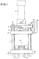
- two vertical guide posts 1 are securely mounted on a base plate 2 which is secured on a table 2a.
- a movable plate 4 is slidably mounted on the guide posts 1 by slidably engaging a guide bush 3 with each guide post 1.
- a conventional die set is composed by the four members 1, 2, 3 and 4.
- a horizontal cylinder plate 7 is secured to the guide post 1 at the top of each post and secured thereto by a screw 8.
- a hydraulic cylinder 5 such as an oil hydraulic cylinder or pneumatic cylinder is vertically mounted on the cylinder plate 7 and secured thereto by screws 6.
- a piston rod 9 of the cylinder 5 has a screw thread.
- the piston rod 9 is secured to the movable plate 4 by engaging the screw thread with a thread formed in the movable plate and locked by a lock nut 10.
- a lower die 17 is mounted and an upper die 17a is secured to the underside of the movable plate 4.
- a read-only sequence controller 12 which is covered by a cover 14 is attached to the cylinder plate 7 through a connector 13 in order to automatically operate the press machine.
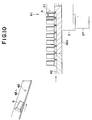
- a progressive multi-stage pick-and-place device 11 for supplying works A and B on the die 17 and for taking out a processed work.
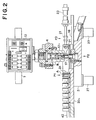
- a pair of slide guide rails 16 are mounted on the base plate 2 parallel with each other at the opposite sides of the lower die 17.
- a pair of slide blocks 15 are slidably mounted on each of the guide rails 16 at a predetermined distance therebetween.
- An L-shaped supporting plate 19 is secured to each pair of slide blocks 15.
- Two pairs of gripping actuators are provided on the supporting plates 19.
- Each gripping actuator comprises opposite pneumatic cylinders 18 and 18a secured to the opposite supporting plates 19.
- the cylinders 18 and 18a are positioned on a first position P1 and a second position P2 at a predetermined equidistance, respectively.
- the ends of the supporting plates 19 are connected by a connecting plate 20.
- Opposite gripping fingers 21 are secured to piston rods 18b of cylinders 18 and 18a of each of the gripping actuators and by nuts 22 for gripping a work A.
- a supporting plate 20a is secured to the ends of the slide guide rails 16.
- a pneumatic cylinder 23 is secured to the supporting plate 20a and a piston rod 24 is connected to the connecting plate 20.
- the cylinders 18 and 18a on the supporting plates 19 are reciprocated on the slide guide rails 16 between the positions P1, P2 and P3 by the operation of the cylinder 23, which will be described hereinafter in detail.
- a pair of lifting devices for lifting the pick-and-place device 11 are provided on the underside of the slide guide rail 16.
- Each of the lifting devices has a guide post 25 which is secured to the guide rail 16 and slidably engaged in a guide bush 26 embedded in the base plate 2 by force fitting.
- a vertical pneumatic cylinder 27 is secured on the underside of the base plate 2, corresponding to each of the guide posts 25 and a piston rod 28 of the cylinder 27 is connected to the guide post 25.
- a parts-feeder 29 is provided for automatically lining up a plurality of works B.
- a pair of vertical pneumatic cylinders 31 are secured on a holding plate 30 which is securely mounted on the base plate 2.
- a slide guide rail 16a is secured to piston rods 32 of the cylinders 31 by screws 33.
- a pair of slide blocks 15a are slidably mounted on the slide guide rail 16a.
- a supporting plate 34 is secured to the slide blocks 15a.
- a horizontal pneumatic cylinder 35 is secured to the supporting plate 34 through a connecting plate 35b, and a piston rod 36 of the cylinder 35 is connected to the slide guide rail 16a through a connecting plate 36b.
- On the underside of the supporting plate 34 a horizontal pneumatic cylinder 38 having a chuck 37 is secured.
- the chuck 37 is opened in a normal state.
- the chuck is closed for gripping the work B and opened again for releasing the work in accordance with the operation of the cylinder 38.
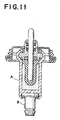
- the work A is a heat conductive cylinder for a thermo-actuator provided in a wax-pellet thermostat for a cooling system of an automotive engine.
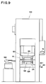
- Fig. 9 shows a cold forging automatic press machine of a capacity of 160t according to the present invention for producing the works A.
- the press machine 123 has a parts-feeder 124 and a die set 125 provided with a pick-and-place device according to the present invention.
- a base plate 2A of the die set 125 is slidably mounted on guide posts 1A and secured to a holster 126, and a movable plate 4A of the die set is secured to a slider 127 of the press machine.
- a sensor 40 is provided on a shoot 42a and the sequence controller 12 is mounted on the machine.
- a progressive multi-stage cold forging press machine is formed.
- the machine is sequentially operated at three processes with a full automatic control to press a bar material of copper of 15mm in outer diameter and 14mm in length to produce cylindrical works A.
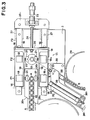
- the works A are fed by the shoot 42a of the cold forging automatic press machine to a parts-feeder 29a (Fig. 3) and lined up in a guide groove 42 formed on a guide plate 30a mounted on the base plate 2.
- the head of the works A is stopped at the first position P1.
- the slide guide rails 16 are lowered by the operations of cylinders 27 to lower the cylinders 18 and 18a, and the piston rods 18b of the cylinders 18 and 18a are moved in the forward directions so that the corresponding fingers 21 are closed to grip the head work A in the guide groove 42 at the first position P1. Then, the slide guide rails 16 are upwardly moved and the cylinder 23 is operated to horizontally move the supporting plates 19 on the slides 15 along the guide rails 16.
- the cylinders 18 and 18a at the first position P1 are moved to the second position P2 and the cylinders 18 and 18a at the second position P2 are moved to the third position P3.
- the slide guide rails 16 are lowered again, at the position P2, the work A is engaged with the lower die 17, and then the piston rods 18b of the cylinders 18 and 81a are retracted so that the fingers 21 are disengaged from the work A. Thereafter, the cylinders 18 and 18a are raised and returned to the first position P1 and the second position P2, respectively.
- automatic centering means is provided as described below.
- each of the cylinders 18a at a side of the machine is set to a larger value than that of the cylinder 18 at the other side, so that each cylinder 18a has a larger air pressure than that of the cylinder 18. Therefore, the work A engaged with the finger 21 of the cylinder 18a is not moved if the work A is pushed by the finger 21 of the cylinder 18. Namely, the position of the work A is determined by only the finger 21 of the cylinder 18a. Thus, the centering of the work is accurately determined with respect to the die 17 by the cylinder 18a. Consequently, the break of the die due to eccentric positioning of the work is prevented.
- the slide guide rail 16a is lowered by the cylinders 31 to lower the cylinder 38 on the supporting plate 34.
- the chuck 37 operatively connected to the piston rod of the cylinder 38 grips the head work B and the guide rail 16a is upwardly moved.
- the supporting plate 34 on the slide blocks 15a is horizontally moved along the guide rail 16a by the operation of the cylinder 35 to the die 17.
- the guide rail 16a is lowered at the position P2 and the chuck 37 is opened so that the work B is inserted in the work A. Thereafter, the supporting plate 34 is returned to the initial position.
- the movable plate 4 is lowered by the operation of the hydraulic cylinder 5 to press the work B to the work A with the upper and lower dies 17 and 17a.
- the work B is press-fitted in the work A.
- the plate 4 is upwardly moved.
- the slide guide rails 16 are lowered.
- the fingers 21 of the cylinders 18 and 18a at the second position P2 grip the pressed work, and the fingers 21 of the cylinders 18 and 18a at the first position P1 grip the next work A.
- the supporting plates 19 are raised and moved to the right in Fig. 3 so that the cylinders 18 and 18a at the second position P2 are moved to the third position P3.
- the cylinders are lowered and the fingers are retracted.
- the pressed work is disengaged from the fingers 21 to be discharged in a shoot.
- the cylinders 18 and 18a at the first position P1 are moved to the second position P2 where the next work A is engaged with the die 17 by the fingers 21.
- the next work B is engaged in the work A and pressed by the dies 17 and 17a in the same manners as described hereinbefore.
- Fig. 11 shows a thermo-actuator comprising works A A and B provided in a wax-pellet thermostat for a cooling system of an automotive engine.
- a progressive assembly line for manufacturing the thermostat can be composed.
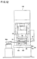
- Fig. 12 shows a power press machine 128 as a third embodiment of the present invention.
- the press machine 128 has a parts-feeder 124a at an inlet thereof and a die set 129 provided with a pick-and-place device according to the present invention.
- a base plate 2B of the die set 129 is secured to a holster 130, and a movable plate 4B of the die set is slidably mounted on guide posts 1B and secured to a slider 131 of the power press machine.
- the sensor 40 is provided on the shoot 42a and the sequence controller 12 is mounted on the machine. Thus, a progressive multi-stage power press and assembly machine is formed.
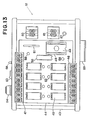
- the read-only sequence controller 12 comprises a read clock pulse control unit 43 having a supply source and an output relay unit 44 mounted on the clock pulse control unit 43.
- the output relay unit 44 comprises a board detachably secured to the control unit 43.
- a number of relays 45 such as eight relays are mounted on the board.
- Terminal units 46 and 47 are disposed adjacent to the relay unit 44.
- the terminal unit 46 has eight terminals for four relays and the terminal unit 47 has ten terminals for the other four relays and for an alternating current power supply.
- An EPROM 48 is detachably fixed to a connector 49.
- Numeral 50 is a transistor array, and 51 is a connector for the clock pulse control unit 43 and the output relay unit 44.
- Eight displays 52 each comprising an LED are provided for displaying the operation of each relay.
- a power switch 53 On the read clock pulse control unit 43, a power switch 53, fuse 54, pilot lamp 55 of an LED, abnormality display 56 of an LED, start switch 57, reset switch 58, input terminals 59, a preset code switch 60 for a main circuit A, and a preset code switch 61 for a sub-circuit B are provided.
- a program for controlling the above described sequential operation is stored in the EPROM 48.
- Fig. 6 shows a transparent program sheet 120 for storing a program.
- the sheet is provided with predetermined items such as parallel data lines 120a printed by opaque ink thereon.
- a program comprising an eight-step time chart is formed by adhering opaque tapes 121 on the parallel data lines 120a.
- the opaque tape 121 is cut by a cutter.
- the time chart is easily changed.
- Fig. 8 shows an EPROM programmer 122 for storing the program stored in the program sheet 120 in the EPROM 48.
- the program sheet 120 is inserted into an opening 41 of the programmer 122 and extracted from another opening (not shown) provided on an opposite side thereof.
- the data on the program sheet 120 is stored in the EPROM 48.
- the EPROM 48 is detachably fixed to the read-only sequence controller 12.
- the circuit comprises the main circuit A and the sub-circuit B which are divided by a dot-dash line in Fig. 15.
- the cycle time of the main circuit A is set to 2.5 seconds by the present code switch 60.
- the cycle time of the sub-circuit B is set to 1.5 seconds by the preset code switch 61.
- the supply voltage Vcc is obtained by a switching regulator 62, and a system supply voltage is applied to an initial reset circuit 63, so that an inverter 64 produces an output at a 1 level.
- the output is inverted into a 0 level by an inverter 65 to reset or set each of R-S latches of first to sixth flip-flops.
- a second flip-flop 73 is set through a 2-input NAND gate 74.
- a one-shot pulse "0" appears at an output of a one-shot pulse generating circuit 75.
- a fourth flip-flop 78 When a fourth flip-flop 78 is reset through a 2-input NAND gate 79, the output at a 0 level is applied to a reset input R of a clock pulse generating circuit 80 to stop the operation thereof.
- the 0-level output is further applied to inputs PE of presettable down counters 82 and 83 through a 2-input NAND gate 81 to preset the digit "15" of preset code switch 61 in counters 83 and 82, respectively.
- the 0 output of the sixth flip-flop 87 is further applied to a seventh flip-flop 91 through a 2-input NAND gate 90 and to a clock pulse generating circuit 94 provided with a crystal oscillator through an inverter 92 and a 2-input NOR gate 93 to stop producing clock pulses.
- the sixth flip-flop 87 When the start switch 57 of the main circuit A is depressed, the sixth flip-flop 87 is set through a chatter preventing circuit C and an inverter 95. Thus, an output at a 1 level is applied to the clock pulse generating circuit 94 through the inverter 92 and the 2-input NOR gate 93.
- the output of the clock pulse generating circuit 94 provided with a crystal oscillator is 10 Hz, as clock pulses.
- the clock pulses are applied to clock lines C of the presettable down counters 71 and 72, respectively.
- the output "0" of the gate 98 is further applied to the set terminal of the seventh flip-flop 91 through an inverter 99.
- a command signal of 1 level is applied from the seventh flip-flop 91 to the sub-circuit B through a transistor 100 and an inverter 101.
- the output of the inverter 97 is inverted into "0" to reset the seventh flip-flop 91 through a 2-input NAND gate 90.
- the command signal is continuously applied to a reset terminal R of the second flip-flop 73 of the sub-circuit B at every 2.5 seconds.
- the output "1" of the fourth flip-flop 78 is applied to a 3-input NAND gate 102, and three inputs thereof go to "1".
- the gate 102 produces an output at a 0 level which is applied to the terminal CI of the presettable down counter 82 to produce clock pulses.
- the one-shot pulse "1" of the one-shot pulse generating circuit 75 is further applied to the reset terminal of the third flip-flop 76, the output 0 thereof is applied to the terminal CE of the EPROM 48 through the connector 51 and the EPROM in turn is set to an output state.
- each read clock pulse is generated from the gate 105.
- the read clock pulse is applied to the clock line C of a binary counter 106. Accordingly, the binary counter 106 produces outputs through address lines Q1 to Q7, so that the outputs are applied to the address in the EPROM 48 through the connector 51.
- the EPROM 48 produces a data signal in response to the address signals, so that respective actuators for cylinders of the press machine are operated through relay unit 44.
- Time of one cycle is decided by the number of read clock pulses. Operation in the case of 100 read clock pulses in one cycle will be explained hereinafter.
- address lines Q3, Q6 and Q7 of the binary counter 106 are selected as the inputs of a 3-input NAND gate 107. Since the binary number of "100" is 1100100, when the 100th read clock pulse is applied to the input of the binary counter 106, outputs on the address lines Q3, Q6 and Q7 go to "1" and the 3-input NAND gate 107 produces a one-cycle end signal "0".
- the third flip-flop 76 is set through the 2-input NAND gate 77, so that an output 1 is applied to CE of the EPROM 48 to stop producing the output.
- the fifth flip-flop 84 is set through an inverter 108.
- a first input of the abnormality signal output gate of 2-input NAND gate 86 is changed to "1".
- the one cycle end signal 0 is applied to the 3-input NAND gate 102, so that a signal at the "1" level is applied to CI of the counter 82 through the gate 102.
- the fourth flip-flop 78 is reset through the 2-input NAND gate 79 to stop the clock pulse generating circuit 80.
- a signal having a 0 level is applied to the set terminal of the second flip-flop 73 through an input terminal 109, chatter preventing circuit C, Schmitt circuit, inverter and 2-input NAND gate 74.
- the fifth flip-flop 84 is reset through 2-input NAND gate 85 to change the first input signal of the abnormality signal output gate of 2-input NAND gate 86 into a "0".
- the second flip-flop 73 is reset by the command signal of the main circuit A at the next 2.5 seconds, thereby re-starting the operations of the sub-circuit B and actuators of the machine. The operations of the actuators are continued unless an abnormality occurs.
- the reset switch 58 is depressed and the start switch 57 is depressed, so that the machine starts operation.
- press work and assembling are combined to provide a progressive automatic press and assembly machine. Since the press machine is formed extremely small in size, the machine can be operated on a table, thereby improving operability at a low cost.
Landscapes
- Engineering & Computer Science (AREA)
- Mechanical Engineering (AREA)
- Press Drives And Press Lines (AREA)
- Automatic Assembly (AREA)
- Mounting, Exchange, And Manufacturing Of Dies (AREA)
Applications Claiming Priority (2)
| Application Number | Priority Date | Filing Date | Title |
|---|---|---|---|
| JP5187689A JPH071199A (ja) | 1993-06-21 | 1993-06-21 | 多工程順送の自動プレス機械 |
| JP187689/93 | 1993-06-21 |
Publications (2)
| Publication Number | Publication Date |
|---|---|
| EP0633094A1 EP0633094A1 (en) | 1995-01-11 |
| EP0633094B1 true EP0633094B1 (en) | 1998-09-09 |
Family
ID=16210429
Family Applications (1)
| Application Number | Title | Priority Date | Filing Date |
|---|---|---|---|
| EP94109502A Expired - Lifetime EP0633094B1 (en) | 1993-06-21 | 1994-06-20 | Multi-stage automatic press and assembly machine |
Country Status (10)
| Country | Link |
|---|---|
| US (1) | US5519932A (OSRAM) |
| EP (1) | EP0633094B1 (OSRAM) |
| JP (1) | JPH071199A (OSRAM) |
| KR (1) | KR0136234B1 (OSRAM) |
| CN (1) | CN1056336C (OSRAM) |
| AU (1) | AU669440B2 (OSRAM) |
| CA (1) | CA2125752C (OSRAM) |
| DE (1) | DE69413142T2 (OSRAM) |
| RU (1) | RU2104817C1 (OSRAM) |
| TW (1) | TW307712B (OSRAM) |
Cited By (2)
| Publication number | Priority date | Publication date | Assignee | Title |
|---|---|---|---|---|
| CN107498281A (zh) * | 2017-09-04 | 2017-12-22 | 梦天木门集团有限公司 | 一种节能型门芯板组件组装装置 |
| US10535970B2 (en) | 2017-01-25 | 2020-01-14 | International Business Machines Corporation | Press-fit apparatus for connectors |
Families Citing this family (54)
| Publication number | Priority date | Publication date | Assignee | Title |
|---|---|---|---|---|
| JPH11797A (ja) * | 1997-06-06 | 1999-01-06 | Giichi Kuze | ダイセット型多工程順送のロボット機械 |
| US6253448B1 (en) * | 1999-03-23 | 2001-07-03 | Electroimpact, Inc. | Gripper systems for rivets and collars used in large-scale assembly operations |
| US7592495B2 (en) * | 2000-07-11 | 2009-09-22 | King Industries | Compositions of Group II and/or Group III base oils and alkylated fused and/or polyfused aromatic compounds |
| KR100419958B1 (ko) * | 2001-05-29 | 2004-03-03 | 주식회사 대흥알앤티 | 자동 부싱 스웨징기 |
| JP2005219097A (ja) * | 2004-02-05 | 2005-08-18 | Daido Machinery Ltd | 多段式圧造成形機 |
| JP2005224820A (ja) * | 2004-02-10 | 2005-08-25 | Daido Machinery Ltd | 多段式圧造成形機 |
| US7021111B2 (en) * | 2004-07-08 | 2006-04-04 | Fwu Kuang Enterprises Co., Ltd. | Forging machine with a guiding roller mechanism for guiding movement of a sliding plate unit |
| FR2884162B1 (fr) * | 2005-04-12 | 2008-12-19 | Renault Sas | Dispositif de frettage pour l'emmanchement d'un pignon sur un arbre |
| JP4382019B2 (ja) * | 2005-09-02 | 2009-12-09 | 本田技研工業株式会社 | コンロッドのブッシュの供給圧入装置 |
| JP4937361B2 (ja) * | 2008-02-20 | 2012-05-23 | 平田機工株式会社 | 生産装置 |
| CN101905415B (zh) * | 2010-07-12 | 2011-12-07 | 西安交通大学 | 一种用于盘式周向多根拉杆转子的拉杆液压预紧装置 |
| CN102133703A (zh) * | 2010-12-29 | 2011-07-27 | 尹贤海 | 一种发动机缸套装配检测机 |
| CN103372615B (zh) * | 2012-04-18 | 2015-06-03 | 珠海格力电器股份有限公司 | 冲铆夹紧装置 |
| FR2992876B1 (fr) * | 2012-07-09 | 2015-01-30 | Pronic | Dispositif d'insertion de bague |
| CN102794644A (zh) * | 2012-08-31 | 2012-11-28 | 杭州日月电器股份有限公司 | 一种智能电子自动组装机 |
| KR101482170B1 (ko) * | 2013-04-29 | 2015-01-14 | 임국건 | 작업용 차량의 그릴 제조장치 |
| CN103962469B (zh) * | 2014-05-29 | 2016-08-17 | 苏州瑞玛金属成型有限公司 | 拉深类产品无料带运送装置 |
| CN104191203A (zh) * | 2014-08-22 | 2014-12-10 | 苏州昌飞自动化设备厂 | 大型电热棒双头旋转压接机的横向传送机构 |
| CN104308019B (zh) * | 2014-10-23 | 2016-05-18 | 平湖市品耀机器自动化有限公司 | 全自动螺帽压扁成型机送料机构 |
| CN104723106A (zh) * | 2015-03-31 | 2015-06-24 | 吴中区木渎蒯斌模具加工厂 | 简易滑轨组装机的导珠压入装置 |
| CN104923492B (zh) * | 2015-06-11 | 2017-11-17 | 江苏大学 | 非接触式镜片瑕疵分拣装置 |
| CN104942152B (zh) * | 2015-06-26 | 2017-02-01 | 燕山大学 | 一种冲压模具组合式压边圈 |
| CN105216173A (zh) * | 2015-09-30 | 2016-01-06 | 芜湖市万华塑料制品有限公司 | 一种塑料件冲压模具组装台 |
| CN105149931A (zh) * | 2015-10-19 | 2015-12-16 | 无锡清杨机械制造有限公司 | 一种治具 |
| CN106514253A (zh) * | 2016-12-28 | 2017-03-22 | 重庆市银钢通科技有限公司 | 一种凸轮装配分选装置 |
| CN108620864A (zh) * | 2017-03-16 | 2018-10-09 | 上海轩田工业设备有限公司 | 一种玻珠焊圈自动组装设备 |
| CN107486721B (zh) * | 2017-06-26 | 2023-10-03 | 东莞洁澳思精密科技股份有限公司 | 一种齿轮加工设备 |
| CN107486533B (zh) * | 2017-09-29 | 2019-02-05 | 宁波市鄞州风名工业产品设计有限公司 | 一种三次冷轧头部成型机 |
| CN108177018A (zh) * | 2018-03-20 | 2018-06-19 | 安徽工程大学 | 一种圆柱工件上料压紧装置 |
| CN108801190A (zh) * | 2018-05-25 | 2018-11-13 | 浙江特利隆精密机械有限公司 | 一种多工位自动皮带轮检测仪 |
| CN108772678B (zh) * | 2018-08-01 | 2023-06-16 | 捷云智能装备(苏州)有限公司 | 集成式二级递进抬升装置、其加工方法及防压损构件压装机 |
| CN109531107A (zh) * | 2018-12-07 | 2019-03-29 | 安徽金寨金鸿诺科技有限公司 | 一种半自动化方管组装设备 |
| CN109465619B (zh) * | 2019-01-02 | 2020-01-14 | 盛瑞传动股份有限公司 | 合箱设备 |
| CN110303324A (zh) * | 2019-06-24 | 2019-10-08 | 上海飞尔汽车零部件股份有限公司 | 一种金属镶件压入etrs电子排挡支架的工装 |
| CN110587288B (zh) * | 2019-08-19 | 2020-10-09 | 宁波立研智能科技有限公司 | 一种汽车出风口总成的装配设备 |
| CN110948211B (zh) * | 2019-12-17 | 2024-08-09 | 坤泰车辆系统(常州)有限公司 | 互锁式多压头压机 |
| CN113458740B (zh) * | 2020-03-31 | 2024-05-17 | 常州星宇车灯股份有限公司 | 灯具零件自动装配到位检测集成装置 |
| CN111545621A (zh) * | 2020-05-14 | 2020-08-18 | 扬州兆森电子科技有限公司 | 一种用于打印机配件生产的可调行程冲压机 |
| CN111730893A (zh) * | 2020-06-18 | 2020-10-02 | 王志超 | 一种生态产品用降解杯挤压控制系统 |
| US11262131B2 (en) * | 2020-06-26 | 2022-03-01 | L & M Radiator, Inc. | Tube stay installation assembly |
| CN112091587A (zh) * | 2020-08-31 | 2020-12-18 | 宁波市鄞州承润科技有限公司 | 一种锂电池装配装置的工作方法 |
| CN112253589B (zh) * | 2020-10-15 | 2022-04-29 | 浏阳市胡记农林科技开发有限公司 | 一种食用油瓶盖密封垫粘接设备 |
| CN113022002B (zh) * | 2021-04-08 | 2024-06-14 | 南通锻压设备如皋有限公司 | 一种板框缠绕组合式钛电极压块成型装备 |
| CN113547298B (zh) * | 2021-07-12 | 2022-12-06 | 烟台市正海包装材料有限公司 | 一种千秋盖组合机 |
| CN113814700B (zh) * | 2021-10-20 | 2023-01-06 | 苏州通锦精密工业股份有限公司 | 一种双工位泵体球涨式堵头压装设备 |
| CN113960974B (zh) * | 2021-12-22 | 2022-03-22 | 南京尚景智造科技有限公司 | 一种发动机缸体堵盖压装控制方法及系统 |
| CN115138738A (zh) * | 2022-05-26 | 2022-10-04 | 王力安防科技股份有限公司 | 一种可自动换模的冲压设备 |
| KR102505120B1 (ko) | 2022-11-03 | 2023-02-28 | 박진오 | 광케이블용 엔드캡 반사판 조립장치 |
| CN117020091B (zh) * | 2023-07-07 | 2024-04-05 | 重庆荆江汽车半轴股份有限公司 | 一种多工位立式摆辗机 |
| CN116852072B (zh) * | 2023-07-12 | 2024-05-03 | 合肥亿昌兴精密机械有限公司 | 冰箱底座一体式装配成型装置及装配成型方法 |
| CN117124071B (zh) * | 2023-07-18 | 2025-10-21 | 陕西法士特汽车传动集团有限责任公司 | 一种adb球轮组件自动装配装置及工作方法 |
| CN117484136B (zh) * | 2023-11-02 | 2024-05-07 | 广东肇庆德通有限公司 | 一种外转子管道换气扇风轮压装专用装置 |
| CN117226478B (zh) * | 2023-11-13 | 2024-01-30 | 张家港市锦力标准件制造有限公司 | 一种螺栓生产装配机 |
| CN119910068B (zh) * | 2025-02-21 | 2025-08-22 | 广东广润精密制造有限公司 | 一种抽屉滑轨的加工方法 |
Family Cites Families (23)
| Publication number | Priority date | Publication date | Assignee | Title |
|---|---|---|---|---|
| US2155958A (en) * | 1937-02-03 | 1939-04-25 | Schmidt Alfred | Shell assembling machine |
| US3077660A (en) * | 1960-03-07 | 1963-02-19 | Western Electric Co | Article-assembling apparatus |
| DE1170893B (de) * | 1960-09-30 | 1964-05-27 | Metallwaren Und Maschinenfabri | Vorrichtung zur UEberwachung des Auswurfes einzelner bearbeiteter Werkstuecke |
| US3319087A (en) * | 1964-04-22 | 1967-05-09 | Ind Controls Inc | Control system for automatic machine |
| GB1169524A (en) * | 1965-12-06 | 1969-11-05 | Aida Tekkosho Kk | Unit-Type Transfer Press System. |
| US3656139A (en) * | 1970-04-28 | 1972-04-11 | Ind Controls Inc | Malfunction detector |
| US3715077A (en) * | 1970-12-18 | 1973-02-06 | Gen Ind Inc | Sheet metal two-part sprinkler head and apparatus and process for making |
| US3683482A (en) * | 1971-01-14 | 1972-08-15 | American Flange & Mfg | Closure flange feed apparatus |
| US3798736A (en) * | 1971-10-27 | 1974-03-26 | E Gibbons | Rubber stamp assembler |
| JPS50143805A (OSRAM) * | 1974-05-09 | 1975-11-19 | ||
| US3939992A (en) * | 1974-09-26 | 1976-02-24 | Mikulec Richard A | Workpiece transfer mechanism |
| US4178672A (en) * | 1978-05-17 | 1979-12-18 | Amico Peter J | Apparatus for assembling and banding an expansion shell |
| US4257153A (en) * | 1979-04-23 | 1981-03-24 | Amico Peter J | Device for assembling an expansion shell |
| SU984585A1 (ru) * | 1980-06-09 | 1982-12-30 | За витель ) Б, Бориславский и В. С. К | Грейферный механизм подачи к штампу дл в зки крючковых цепей |
| JPS57146431A (en) * | 1981-03-06 | 1982-09-09 | Aida Eng Ltd | Driving device for feed bar in transfer press |
| US4462521A (en) * | 1981-12-29 | 1984-07-31 | Sumitomo Heavy Industries, Ltd. | Transfer mechanism |
| US4428221A (en) * | 1982-01-22 | 1984-01-31 | Owens Roland G | Transfer apparatus for straight side press |
| US4454743A (en) * | 1982-02-02 | 1984-06-19 | Redicon Corporation | Integrated container manufacturing system and method |
| JPS59120033U (ja) * | 1983-01-28 | 1984-08-13 | アイダエンジニアリング株式会社 | プレス間搬送装置 |
| JPS601856U (ja) * | 1983-06-20 | 1985-01-09 | 瀬戸内金網商工株式会社 | 金網柵 |
| AU583988B2 (en) * | 1986-06-02 | 1989-05-11 | Yoshikazu Kuze | Read-only sequence control system |
| JPH07112639B2 (ja) * | 1989-06-28 | 1995-12-06 | 義一 久世 | ダイセット型自動プレス機械の製造方法 |
| JP2820758B2 (ja) * | 1990-01-30 | 1998-11-05 | 川鉄アドバンテック株式会社 | トランスファ・プレスの異常検出装置 |
-
1993
- 1993-06-21 JP JP5187689A patent/JPH071199A/ja active Pending
-
1994
- 1994-06-13 CA CA002125752A patent/CA2125752C/en not_active Expired - Fee Related
- 1994-06-16 AU AU64720/94A patent/AU669440B2/en not_active Ceased
- 1994-06-16 RU RU94021343A patent/RU2104817C1/ru active
- 1994-06-17 TW TW083105497A patent/TW307712B/zh active
- 1994-06-20 US US08/262,640 patent/US5519932A/en not_active Expired - Fee Related
- 1994-06-20 DE DE69413142T patent/DE69413142T2/de not_active Expired - Fee Related
- 1994-06-20 EP EP94109502A patent/EP0633094B1/en not_active Expired - Lifetime
- 1994-06-21 CN CN94107501A patent/CN1056336C/zh not_active Expired - Fee Related
- 1994-06-21 KR KR1019940013981A patent/KR0136234B1/ko not_active Expired - Fee Related
Cited By (4)
| Publication number | Priority date | Publication date | Assignee | Title |
|---|---|---|---|---|
| US10535970B2 (en) | 2017-01-25 | 2020-01-14 | International Business Machines Corporation | Press-fit apparatus for connectors |
| US11289869B2 (en) | 2017-01-25 | 2022-03-29 | International Business Machines Corporation | Manufacturing a press-fit apparatus |
| CN107498281A (zh) * | 2017-09-04 | 2017-12-22 | 梦天木门集团有限公司 | 一种节能型门芯板组件组装装置 |
| CN107498281B (zh) * | 2017-09-04 | 2023-09-15 | 梦天家居集团股份有限公司 | 一种节能型门芯板组件组装装置 |
Also Published As
| Publication number | Publication date |
|---|---|
| CA2125752C (en) | 2000-08-15 |
| RU2104817C1 (ru) | 1998-02-20 |
| CN1056336C (zh) | 2000-09-13 |
| KR950000251A (ko) | 1995-01-03 |
| US5519932A (en) | 1996-05-28 |
| KR0136234B1 (ko) | 1998-07-01 |
| AU6472094A (en) | 1995-01-05 |
| DE69413142D1 (de) | 1998-10-15 |
| TW307712B (OSRAM) | 1997-06-11 |
| RU94021343A (ru) | 1997-05-20 |
| DE69413142T2 (de) | 1999-01-28 |
| AU669440B2 (en) | 1996-06-06 |
| JPH071199A (ja) | 1995-01-06 |
| CA2125752A1 (en) | 1994-12-22 |
| EP0633094A1 (en) | 1995-01-11 |
| CN1117410A (zh) | 1996-02-28 |
Similar Documents
| Publication | Publication Date | Title |
|---|---|---|
| EP0633094B1 (en) | Multi-stage automatic press and assembly machine | |
| JP2003122427A (ja) | 設備モニタ装置 | |
| KR101005210B1 (ko) | 기계 부품 제조장치 | |
| CA2019951C (en) | Press machine | |
| CN110405687A (zh) | 一种剪刀脚的装配设备 | |
| JPH07275971A (ja) | トランスファー装置のトルク監視による異常検出装置 | |
| KR900006300B1 (ko) | 서어보모우터로 구동되는 사출성형기의 제어방식 | |
| JPH11114757A (ja) | 工具交換制御方法 | |
| JPH0550479A (ja) | 射出成形機の型開閉オプシヨン動作の設定方法 | |
| CN109551813B (zh) | 一种送料控制装置及其送料控制方法 | |
| JPH081400A (ja) | 多工程順送の自動プレス機械 | |
| CN114558966A (zh) | 一种细长类零件端部自动化锻造装置以及方法 | |
| CN208444195U (zh) | 钢质门门框锁孔数控定位电气控制装置 | |
| US3163087A (en) | Machine tool control system | |
| JP4690826B2 (ja) | 射出成形機 | |
| KR100403139B1 (ko) | 자동 팔레트 교환기의 팔레트 충돌방지 장치 | |
| SU1311907A1 (ru) | Устройство дл выдачи заготовок | |
| JPH0679589A (ja) | 生産システム制御装置 | |
| JPH06106459A (ja) | トランスファマシン | |
| JPH11179445A (ja) | カートリッジ式パンチプレス | |
| JP2749438B2 (ja) | 射出成形機の動作表示装置 | |
| JPH0557499A (ja) | ワーク搬送ロボツトの制御装置 | |
| KR0115951Y1 (ko) | 자동취출장치의 제어장치 | |
| JPH01150616A (ja) | 取付部品の定数供給装置 | |
| GB1597947A (en) | Control circuits in or for power presses |
Legal Events
| Date | Code | Title | Description |
|---|---|---|---|
| PUAI | Public reference made under article 153(3) epc to a published international application that has entered the european phase |
Free format text: ORIGINAL CODE: 0009012 |
|
| 17P | Request for examination filed |
Effective date: 19940620 |
|
| AK | Designated contracting states |
Kind code of ref document: A1 Designated state(s): DE FR GB IT |
|
| 17Q | First examination report despatched |
Effective date: 19960617 |
|
| GRAG | Despatch of communication of intention to grant |
Free format text: ORIGINAL CODE: EPIDOS AGRA |
|
| GRAG | Despatch of communication of intention to grant |
Free format text: ORIGINAL CODE: EPIDOS AGRA |
|
| GRAH | Despatch of communication of intention to grant a patent |
Free format text: ORIGINAL CODE: EPIDOS IGRA |
|
| GRAH | Despatch of communication of intention to grant a patent |
Free format text: ORIGINAL CODE: EPIDOS IGRA |
|
| GRAA | (expected) grant |
Free format text: ORIGINAL CODE: 0009210 |
|
| AK | Designated contracting states |
Kind code of ref document: B1 Designated state(s): DE FR GB IT |
|
| REF | Corresponds to: |
Ref document number: 69413142 Country of ref document: DE Date of ref document: 19981015 |
|
| ET | Fr: translation filed | ||
| PLBE | No opposition filed within time limit |
Free format text: ORIGINAL CODE: 0009261 |
|
| STAA | Information on the status of an ep patent application or granted ep patent |
Free format text: STATUS: NO OPPOSITION FILED WITHIN TIME LIMIT |
|
| 26N | No opposition filed | ||
| PGFP | Annual fee paid to national office [announced via postgrant information from national office to epo] |
Ref country code: GB Payment date: 20010608 Year of fee payment: 8 |
|
| PGFP | Annual fee paid to national office [announced via postgrant information from national office to epo] |
Ref country code: FR Payment date: 20010621 Year of fee payment: 8 |
|
| PGFP | Annual fee paid to national office [announced via postgrant information from national office to epo] |
Ref country code: DE Payment date: 20010726 Year of fee payment: 8 |
|
| REG | Reference to a national code |
Ref country code: GB Ref legal event code: IF02 |
|
| PG25 | Lapsed in a contracting state [announced via postgrant information from national office to epo] |
Ref country code: GB Free format text: LAPSE BECAUSE OF NON-PAYMENT OF DUE FEES Effective date: 20020620 |
|
| PG25 | Lapsed in a contracting state [announced via postgrant information from national office to epo] |
Ref country code: DE Free format text: LAPSE BECAUSE OF NON-PAYMENT OF DUE FEES Effective date: 20030101 |
|
| GBPC | Gb: european patent ceased through non-payment of renewal fee |
Effective date: 20020620 |
|
| PG25 | Lapsed in a contracting state [announced via postgrant information from national office to epo] |
Ref country code: FR Free format text: LAPSE BECAUSE OF NON-PAYMENT OF DUE FEES Effective date: 20030228 |
|
| REG | Reference to a national code |
Ref country code: FR Ref legal event code: ST |
|
| PG25 | Lapsed in a contracting state [announced via postgrant information from national office to epo] |
Ref country code: IT Free format text: LAPSE BECAUSE OF NON-PAYMENT OF DUE FEES Effective date: 20050620 |