EP0613639B1 - Ausziehführung für Schlubladen - Google Patents
Ausziehführung für Schlubladen Download PDFInfo
- Publication number
- EP0613639B1 EP0613639B1 EP94102388A EP94102388A EP0613639B1 EP 0613639 B1 EP0613639 B1 EP 0613639B1 EP 94102388 A EP94102388 A EP 94102388A EP 94102388 A EP94102388 A EP 94102388A EP 0613639 B1 EP0613639 B1 EP 0613639B1
- Authority
- EP
- European Patent Office
- Prior art keywords
- pull
- rails
- drawer
- rollers
- rail
- Prior art date
- Legal status (The legal status is an assumption and is not a legal conclusion. Google has not performed a legal analysis and makes no representation as to the accuracy of the status listed.)
- Expired - Lifetime
Links
Images


Classifications
-
- A—HUMAN NECESSITIES
- A47—FURNITURE; DOMESTIC ARTICLES OR APPLIANCES; COFFEE MILLS; SPICE MILLS; SUCTION CLEANERS IN GENERAL
- A47B—TABLES; DESKS; OFFICE FURNITURE; CABINETS; DRAWERS; GENERAL DETAILS OF FURNITURE
- A47B88/00—Drawers for tables, cabinets or like furniture; Guides for drawers
- A47B88/40—Sliding drawers; Slides or guides therefor
- A47B88/402—Profiles or supporting structures for supporting single drawers
-
- A—HUMAN NECESSITIES
- A47—FURNITURE; DOMESTIC ARTICLES OR APPLIANCES; COFFEE MILLS; SPICE MILLS; SUCTION CLEANERS IN GENERAL
- A47B—TABLES; DESKS; OFFICE FURNITURE; CABINETS; DRAWERS; GENERAL DETAILS OF FURNITURE
- A47B2210/00—General construction of drawers, guides and guide devices
- A47B2210/0002—Guide construction for drawers
- A47B2210/0029—Guide bearing means
- A47B2210/0043—Wheels
- A47B2210/0045—Wheels whereof only one per slide
-
- A—HUMAN NECESSITIES
- A47—FURNITURE; DOMESTIC ARTICLES OR APPLIANCES; COFFEE MILLS; SPICE MILLS; SUCTION CLEANERS IN GENERAL
- A47B—TABLES; DESKS; OFFICE FURNITURE; CABINETS; DRAWERS; GENERAL DETAILS OF FURNITURE
- A47B2210/00—General construction of drawers, guides and guide devices
- A47B2210/02—Drawers with hollow lateral walls in two parts
Definitions
- the invention relates to a pull-out guide for drawers with cabinet-side Carrier rails and pull-out rails on the shop side, load-bearing on the rails Rollers or sliders are stored and the rails are catwalks for the rollers or Have sliders, the rollers or sliders of the mounting rails with respect to the Rollers or sliders of the pull-out rails perpendicular to the pull-out direction of the Pull-out rails are offset in such a way that the pull-out rails are guided in two lanes.
- the drawer side casters of each drawer are in relation to the body side Carrier rollers offset in a plane perpendicular to the side wall of the furniture
- the object of the invention is to provide a pull-out guide of the type mentioned above improve that it has an anti-lift device that prevents accidental lifting of the Drawer prevented from the cabinet side rails, but taking out the drawer from the furniture body is not hindered, not even then, if there is little free space between the drawers of a furniture body arranged one above the other is available.
- the object of the invention is achieved in that the pull-out rails are horizontal Have rags that protrude under the catwalks of the mounting rails and a lifting device form for the drawer.
- each pull-out rail three has horizontal lobes.
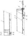
- Fig. 1 shows an end view of a frame of the drawer and on one side of the pull-out guide;
- Fig. 2 shows a side view of the drawer and the
- the Fig. 3 shows a side view of a drawer and a Pull-out guide set with the drawer pulled out;
- the Fig. 4 shows a horizontal section through a frame and a pull-out guide set on one side of the drawer with the drawer closed;
- 5 shows a side view the pull-out rail partly in section;
- 6 shows a horizontal section through a pull-out rail and 7 shows a cross section through a pull-out rail.
- the pull-out guide is on each side of the drawer the drawer frame 1 is covered. It is supported by a mounting rail 4, which is attached to a body side wall, and a pull-out rail 5 on the drawer side wall or the drawer bottom 2 is formed.
- the support rail 4 has a horizontal to the drawer Walkway 6 on the top of a vertical walkway 7 is formed.
- the vertical web 7 carries on front end of the mounting rail 4 a roller 8, the the side of the vertical catwalk opposite the catwalk 6 is attached. That is, the roller 8 is located between the vertical web 7 and the body side wall or the outer wall 1 'of the double-walled drawer frame 1.
- the pull-out rail 5 engages over the catwalk 6 and the vertical catwalk 7 and the roller 8 of the mounting rail 4. Your The catwalk 9 is therefore outside the catwalk 6 of the mounting rail 4. Furthermore, the pull-out rail 5 has an outer one free edge web 10 in which the drawer 1 with its outer wall 1 'is suspended.
- each pull-out rail 5 has two rollers 11 provided, which are arranged one above the other and each from above or from below on the runway 6 of the mounting rail 4 expire.
- each pull-out rail is 5 provided with three horizontal tabs 12 by the side to below the catwalk 6 of the mounting rail 4 protrude. These tabs 12 form a lifting safety device unwanted lifting of the pull-out rail 5 and thus the entire Prevent the drawer from the mounting rails 4.
- each pull-out rail 5 Stored in the foremost tab 12 of each pull-out rail 5 an eccentric 15 which is rotatable about a vertical axis.
- the eccentric 15 bumps, as in particular from FIGS. 5 and 6 can be seen, with the drawer pushed in on the associated one Mounting rail 4.
- By adjusting the eccentric 15 is achieved that when inserting the drawer
- the front panel does not strike the cabinet.
- the distance between the front panel and the furniture body or its Side walls are adjusted by turning the eccentric 15.
- the fact that the driving energy of the drawer between the rails 4, 5 is included, is prevented the front cover is held by the drawer frames 1 loosens.
Landscapes
- Drawers Of Furniture (AREA)
- Fishing Rods (AREA)
- Inorganic Compounds Of Heavy Metals (AREA)
- Crystals, And After-Treatments Of Crystals (AREA)
- Semiconductor Lasers (AREA)
- Platform Screen Doors And Railroad Systems (AREA)
- Lift-Guide Devices, And Elevator Ropes And Cables (AREA)
Description
Claims (3)
- Ausziehführung für Schubladen mit korpusseitigen Tragschienen (4) und ladenseitigen Ausziehschienen (5) wobei an den Schienen (4,5) Tastübertragende Laufrollen (8,11) oder Gleiter gelagert sind und die Schienen (4,5) Laufstege für die Laufrollen (8,11) Gleiter aufweisen, wobei die Laufrollen (8) oder Gleiter der Tragschienen (4) in bezug auf die Laufrollen (11) oder Gleiter der Ausziehschienen (5) senkrecht zur Ausziehrichtung der Ausziehschienen (5) versetzt sind, derart, daß die Ausziehschienen (5) zweispurig geführt sind, dadurch gekennzeichnet, daß die Ausziehschienen (5) horizontale Lappen (12) aufweisen, die unter die Laufstege (6) der Tragschienen (4) ragen und eine Anhebesicherung für die Schublade bilden.
- Ausziehführung nach Anspruch 1, dadurch gekennzeichnet, daß jede Ausziehschiene (5) drei horizontale Lappen (12) aufweist.
- Ausziehführung nach Anspruch 1, dadurch gekennzeichnet, daß die Laufrollen (8) oder Gleiter der Tragschienen (4) an der den Laufstegen (6) der Tragschienen (4) abgewandten Seite gelagert sind.
Applications Claiming Priority (3)
| Application Number | Priority Date | Filing Date | Title |
|---|---|---|---|
| AT412/93 | 1993-03-04 | ||
| AT41293 | 1993-03-04 | ||
| AT0041293A AT400218B (de) | 1993-03-04 | 1993-03-04 | Ausziehführung für schubladen |
Publications (3)
| Publication Number | Publication Date |
|---|---|
| EP0613639A2 EP0613639A2 (de) | 1994-09-07 |
| EP0613639A3 EP0613639A3 (de) | 1998-01-21 |
| EP0613639B1 true EP0613639B1 (de) | 2000-11-29 |
Family
ID=3489943
Family Applications (1)
| Application Number | Title | Priority Date | Filing Date |
|---|---|---|---|
| EP94102388A Expired - Lifetime EP0613639B1 (de) | 1993-03-04 | 1994-02-17 | Ausziehführung für Schlubladen |
Country Status (7)
| Country | Link |
|---|---|
| US (1) | US5395169A (de) |
| EP (1) | EP0613639B1 (de) |
| JP (1) | JP2722167B2 (de) |
| AT (2) | AT400218B (de) |
| CA (1) | CA2116203C (de) |
| DE (1) | DE59409596D1 (de) |
| ES (1) | ES2152268T3 (de) |
Families Citing this family (6)
| Publication number | Priority date | Publication date | Assignee | Title |
|---|---|---|---|---|
| GB9401310D0 (en) * | 1994-01-25 | 1994-03-23 | Metsec Plc | Drawer slide |
| AT648U1 (de) | 1995-03-09 | 1996-03-25 | Blum Gmbh Julius | Ausziehführung für schubladen |
| JP3901415B2 (ja) * | 1999-12-20 | 2007-04-04 | 株式会社リコー | スライドレール |
| AT512899B1 (de) | 2012-11-15 | 2013-12-15 | Blum Gmbh Julius | Verfahren zur Herstellung eines Blechprofils für eine Schubladen-Ausziehführung |
| JP6393631B2 (ja) * | 2015-01-27 | 2018-09-19 | 株式会社イノアックコーポレーション | 車両用引出装置 |
| KR102611208B1 (ko) * | 2016-09-09 | 2023-12-08 | 김종원 | 가구 서랍용 풀아웃 가이드 |
Family Cites Families (16)
| Publication number | Priority date | Publication date | Assignee | Title |
|---|---|---|---|---|
| US1676991A (en) * | 1928-07-10 | A gobi-ora | ||
| US2574162A (en) * | 1950-10-16 | 1951-11-06 | Bertrand M Baker | Roller bearing drawer guide |
| US2747943A (en) * | 1953-08-10 | 1956-05-29 | Frank H Metcalf | Guide structure for drawers and the like |
| GB903221A (en) * | 1958-12-09 | 1962-08-15 | Autoset Production Ltd | Improvements relating to extensible supports for drawers, shelves and other slidablestructures |
| US3026149A (en) * | 1959-06-24 | 1962-03-20 | Garcy Corp | Drawer slide mechanism |
| US2985491A (en) * | 1959-10-09 | 1961-05-23 | Lloyd M Hayes | Adjsutable drawer guide |
| US3477770A (en) * | 1967-05-19 | 1969-11-11 | Impex Corp | Drawer guide |
| US3876263A (en) * | 1973-10-09 | 1975-04-08 | Cooper Slide Sales Inc | Slide assembly for extension table |
| DE2701712C2 (de) * | 1977-01-17 | 1982-05-13 | Hagenhenrich Gmbh & Co Kg Metallwarenfabrik, 4837 Verl | Schubladenführung mit einseitiger Seitenführung |
| US4176890A (en) * | 1978-04-05 | 1979-12-04 | Ajax Hardware Corporation | Drawer and support system |
| NL7901727A (nl) * | 1979-03-05 | 1980-09-09 | Oda V H H J Van De Kamp B V | Ondersteuningsconstructie voor een schuiflade zoals van een bureau of dergelijke. |
| AT378899B (de) * | 1981-02-19 | 1985-10-10 | Blum Gmbh Julius | Ausziehfuehrungsgarnitur fuer schubladen, fachboeden od. dgl. |
| AT387897B (de) * | 1984-12-20 | 1989-03-28 | Blum Gmbh Julius | Unterflur-fuehrungsschienengarnitur |
| US4666221A (en) * | 1986-04-03 | 1987-05-19 | Mayline Company, Inc. | Multidrawer cabinet |
| DE3703051A1 (de) * | 1987-02-03 | 1988-08-11 | Lautenschlaeger Kg Karl | Ausziehfuehrung |
| AT403648B (de) * | 1993-03-30 | 1998-04-27 | Blum Gmbh Julius | Schubladenbausatz |
-
1993
- 1993-03-04 AT AT0041293A patent/AT400218B/de not_active IP Right Cessation
-
1994
- 1994-02-17 AT AT94102388T patent/ATE197755T1/de not_active IP Right Cessation
- 1994-02-17 EP EP94102388A patent/EP0613639B1/de not_active Expired - Lifetime
- 1994-02-17 ES ES94102388T patent/ES2152268T3/es not_active Expired - Lifetime
- 1994-02-17 DE DE59409596T patent/DE59409596D1/de not_active Expired - Fee Related
- 1994-02-22 CA CA002116203A patent/CA2116203C/en not_active Expired - Fee Related
- 1994-02-24 US US08/201,127 patent/US5395169A/en not_active Expired - Fee Related
- 1994-03-04 JP JP6058371A patent/JP2722167B2/ja not_active Expired - Fee Related
Also Published As
| Publication number | Publication date |
|---|---|
| ATE197755T1 (de) | 2000-12-15 |
| ES2152268T3 (es) | 2001-02-01 |
| DE59409596D1 (de) | 2001-01-04 |
| JPH06315419A (ja) | 1994-11-15 |
| CA2116203C (en) | 2001-01-30 |
| JP2722167B2 (ja) | 1998-03-04 |
| ATA41293A (de) | 1995-03-15 |
| EP0613639A2 (de) | 1994-09-07 |
| EP0613639A3 (de) | 1998-01-21 |
| AT400218B (de) | 1995-11-27 |
| US5395169A (en) | 1995-03-07 |
| CA2116203A1 (en) | 1994-09-05 |
Similar Documents
| Publication | Publication Date | Title |
|---|---|---|
| AT407473B (de) | Vollauszug für schubladen | |
| DE2918572C2 (de) | ||
| EP0545329B1 (de) | Ausziehführungsgarnitur für eine Schublade | |
| EP0219733B1 (de) | Vollauszugsgarnitur für Schubladen | |
| EP1168945A1 (de) | Teleskop-schrankauszug | |
| DE8610856U1 (de) | Vollauszugsgarnitur für Schubladen | |
| EP0613639B1 (de) | Ausziehführung für Schlubladen | |
| DE2752779C2 (de) | Ausziehführung für Schubladen o.dgl. | |
| EP0098511B1 (de) | Ausziehführungsgarnitur für Schubladen od.dgl. | |
| EP0809956A2 (de) | Auszugeinrichtung für ein in einem Schrankelement einschieb- und ausziehbaren Einbauteil | |
| DE3010089A1 (de) | Ausziehfuehrung fuer schubladen o.dgl. | |
| DE29619413U1 (de) | Ausziehführungsgarnitur für Schubladen | |
| EP0528218B1 (de) | Mit einer Dreh-Schiebetür verschliessbares Möbelstück, insbesondere Schrank | |
| DE3537335C2 (de) | ||
| DE3120263C2 (de) | Frontauszug für einen Hochschrank, insbesondere Küchenhochschrank | |
| AT399265B (de) | Ausziehführung für schubladen | |
| DE7242315U (de) | Schubkasten mit Führung | |
| EP0333981A1 (de) | Dreh-Schiebetürbeschlag für ein Möbel | |
| DE29718758U1 (de) | Werkzeugwagen | |
| AT393350B (de) | Schubladenauszug | |
| DE2600753A1 (de) | Ausziehtisch, insbesondere hoehenverstellbarer ausziehtisch | |
| AT406109B (de) | Ausziehführungsgarnitur für schubladen | |
| AT403343B (de) | Ausziehführung für schubladen | |
| DE3913953C2 (de) | ||
| DE2625364C3 (de) | Ausziehführung |
Legal Events
| Date | Code | Title | Description |
|---|---|---|---|
| PUAI | Public reference made under article 153(3) epc to a published international application that has entered the european phase |
Free format text: ORIGINAL CODE: 0009012 |
|
| AK | Designated contracting states |
Kind code of ref document: A2 Designated state(s): AT DE ES FR GB IT |
|
| PUAL | Search report despatched |
Free format text: ORIGINAL CODE: 0009013 |
|
| AK | Designated contracting states |
Kind code of ref document: A3 Designated state(s): AT DE ES FR GB IT |
|
| 17P | Request for examination filed |
Effective date: 19980218 |
|
| 17Q | First examination report despatched |
Effective date: 19990629 |
|
| GRAG | Despatch of communication of intention to grant |
Free format text: ORIGINAL CODE: EPIDOS AGRA |
|
| GRAG | Despatch of communication of intention to grant |
Free format text: ORIGINAL CODE: EPIDOS AGRA |
|
| GRAH | Despatch of communication of intention to grant a patent |
Free format text: ORIGINAL CODE: EPIDOS IGRA |
|
| GRAH | Despatch of communication of intention to grant a patent |
Free format text: ORIGINAL CODE: EPIDOS IGRA |
|
| GRAH | Despatch of communication of intention to grant a patent |
Free format text: ORIGINAL CODE: EPIDOS IGRA |
|
| GRAA | (expected) grant |
Free format text: ORIGINAL CODE: 0009210 |
|
| AK | Designated contracting states |
Kind code of ref document: B1 Designated state(s): AT DE ES FR GB IT |
|
| REF | Corresponds to: |
Ref document number: 197755 Country of ref document: AT Date of ref document: 20001215 Kind code of ref document: T |
|
| ITF | It: translation for a ep patent filed | ||
| GBT | Gb: translation of ep patent filed (gb section 77(6)(a)/1977) |
Effective date: 20001129 |
|
| REF | Corresponds to: |
Ref document number: 59409596 Country of ref document: DE Date of ref document: 20010104 |
|
| REG | Reference to a national code |
Ref country code: ES Ref legal event code: FG2A Ref document number: 2152268 Country of ref document: ES Kind code of ref document: T3 |
|
| PGFP | Annual fee paid to national office [announced via postgrant information from national office to epo] |
Ref country code: GB Payment date: 20010214 Year of fee payment: 8 |
|
| PGFP | Annual fee paid to national office [announced via postgrant information from national office to epo] |
Ref country code: FR Payment date: 20010222 Year of fee payment: 8 |
|
| ET | Fr: translation filed | ||
| PLBE | No opposition filed within time limit |
Free format text: ORIGINAL CODE: 0009261 |
|
| STAA | Information on the status of an ep patent application or granted ep patent |
Free format text: STATUS: NO OPPOSITION FILED WITHIN TIME LIMIT |
|
| 26N | No opposition filed | ||
| REG | Reference to a national code |
Ref country code: GB Ref legal event code: IF02 |
|
| PG25 | Lapsed in a contracting state [announced via postgrant information from national office to epo] |
Ref country code: GB Free format text: LAPSE BECAUSE OF NON-PAYMENT OF DUE FEES Effective date: 20020217 |
|
| GBPC | Gb: european patent ceased through non-payment of renewal fee |
Effective date: 20020217 |
|
| PG25 | Lapsed in a contracting state [announced via postgrant information from national office to epo] |
Ref country code: FR Free format text: LAPSE BECAUSE OF NON-PAYMENT OF DUE FEES Effective date: 20021031 |
|
| REG | Reference to a national code |
Ref country code: FR Ref legal event code: ST |
|
| PGFP | Annual fee paid to national office [announced via postgrant information from national office to epo] |
Ref country code: AT Payment date: 20030214 Year of fee payment: 10 |
|
| PGFP | Annual fee paid to national office [announced via postgrant information from national office to epo] |
Ref country code: ES Payment date: 20030226 Year of fee payment: 10 |
|
| PGFP | Annual fee paid to national office [announced via postgrant information from national office to epo] |
Ref country code: DE Payment date: 20030425 Year of fee payment: 10 |
|
| PG25 | Lapsed in a contracting state [announced via postgrant information from national office to epo] |
Ref country code: AT Free format text: LAPSE BECAUSE OF NON-PAYMENT OF DUE FEES Effective date: 20040217 |
|
| PG25 | Lapsed in a contracting state [announced via postgrant information from national office to epo] |
Ref country code: ES Free format text: LAPSE BECAUSE OF NON-PAYMENT OF DUE FEES Effective date: 20040218 |
|
| PG25 | Lapsed in a contracting state [announced via postgrant information from national office to epo] |
Ref country code: DE Free format text: LAPSE BECAUSE OF NON-PAYMENT OF DUE FEES Effective date: 20040901 |
|
| REG | Reference to a national code |
Ref country code: ES Ref legal event code: FD2A Effective date: 20040218 |
|
| PGFP | Annual fee paid to national office [announced via postgrant information from national office to epo] |
Ref country code: IT Payment date: 20070627 Year of fee payment: 14 |
|
| PG25 | Lapsed in a contracting state [announced via postgrant information from national office to epo] |
Ref country code: IT Free format text: LAPSE BECAUSE OF NON-PAYMENT OF DUE FEES Effective date: 20080217 |