EP0611725A1 - Grue montée sur un vehicule - Google Patents
Grue montée sur un vehicule Download PDFInfo
- Publication number
- EP0611725A1 EP0611725A1 EP94102435A EP94102435A EP0611725A1 EP 0611725 A1 EP0611725 A1 EP 0611725A1 EP 94102435 A EP94102435 A EP 94102435A EP 94102435 A EP94102435 A EP 94102435A EP 0611725 A1 EP0611725 A1 EP 0611725A1
- Authority
- EP
- European Patent Office
- Prior art keywords
- crane
- vehicle
- vehicle frame
- driver
- driving
- Prior art date
- Legal status (The legal status is an assumption and is not a legal conclusion. Google has not performed a legal analysis and makes no representation as to the accuracy of the status listed.)
- Granted
Links
Images
Classifications
-
- B—PERFORMING OPERATIONS; TRANSPORTING
- B66—HOISTING; LIFTING; HAULING
- B66C—CRANES; LOAD-ENGAGING ELEMENTS OR DEVICES FOR CRANES, CAPSTANS, WINCHES, OR TACKLES
- B66C23/00—Cranes comprising essentially a beam, boom, or triangular structure acting as a cantilever and mounted for translatory of swinging movements in vertical or horizontal planes or a combination of such movements, e.g. jib-cranes, derricks, tower cranes
- B66C23/62—Constructional features or details
-
- B—PERFORMING OPERATIONS; TRANSPORTING
- B62—LAND VEHICLES FOR TRAVELLING OTHERWISE THAN ON RAILS
- B62D—MOTOR VEHICLES; TRAILERS
- B62D33/00—Superstructures for load-carrying vehicles
- B62D33/06—Drivers' cabs
-
- B—PERFORMING OPERATIONS; TRANSPORTING
- B66—HOISTING; LIFTING; HAULING
- B66C—CRANES; LOAD-ENGAGING ELEMENTS OR DEVICES FOR CRANES, CAPSTANS, WINCHES, OR TACKLES
- B66C23/00—Cranes comprising essentially a beam, boom, or triangular structure acting as a cantilever and mounted for translatory of swinging movements in vertical or horizontal planes or a combination of such movements, e.g. jib-cranes, derricks, tower cranes
- B66C23/18—Cranes comprising essentially a beam, boom, or triangular structure acting as a cantilever and mounted for translatory of swinging movements in vertical or horizontal planes or a combination of such movements, e.g. jib-cranes, derricks, tower cranes specially adapted for use in particular purposes
- B66C23/36—Cranes comprising essentially a beam, boom, or triangular structure acting as a cantilever and mounted for translatory of swinging movements in vertical or horizontal planes or a combination of such movements, e.g. jib-cranes, derricks, tower cranes specially adapted for use in particular purposes mounted on road or rail vehicles; Manually-movable jib-cranes for use in workshops; Floating cranes
- B66C23/42—Cranes comprising essentially a beam, boom, or triangular structure acting as a cantilever and mounted for translatory of swinging movements in vertical or horizontal planes or a combination of such movements, e.g. jib-cranes, derricks, tower cranes specially adapted for use in particular purposes mounted on road or rail vehicles; Manually-movable jib-cranes for use in workshops; Floating cranes with jibs of adjustable configuration, e.g. foldable
-
- B—PERFORMING OPERATIONS; TRANSPORTING
- B60—VEHICLES IN GENERAL
- B60K—ARRANGEMENT OR MOUNTING OF PROPULSION UNITS OR OF TRANSMISSIONS IN VEHICLES; ARRANGEMENT OR MOUNTING OF PLURAL DIVERSE PRIME-MOVERS IN VEHICLES; AUXILIARY DRIVES FOR VEHICLES; INSTRUMENTATION OR DASHBOARDS FOR VEHICLES; ARRANGEMENTS IN CONNECTION WITH COOLING, AIR INTAKE, GAS EXHAUST OR FUEL SUPPLY OF PROPULSION UNITS IN VEHICLES
- B60K7/00—Disposition of motor in, or adjacent to, traction wheel
- B60K7/0015—Disposition of motor in, or adjacent to, traction wheel the motor being hydraulic
Definitions
- the invention relates to a crane vehicle of the type specified in the preamble of claim 1.
- the invention is therefore based on the object of designing a generic crane vehicle in such a way that it can be used in a variety of ways even in confined spaces, can be moved easily and quickly from place to place and is particularly efficient despite small dimensions.
- the technical progress that can be achieved with the aid of the crane vehicle according to the invention results primarily from the fact that the vehicle construction leads to a particularly low overall height, as a result of which low road bridges and low hall gates can be easily passed under, that the crane vehicle according to the invention is suitable for use on the motorway in the sense of the Road Traffic Licensing Regulations (STVZO) , ie, a minimum cruising speed of 62 km / h is permitted and a mechanical steering action on the vehicle wheels to be steered is guaranteed for driving speeds of above 62 km / h. Furthermore, the construction of the crane vehicle according to the invention enables the visibility circle diameter required by the STVZO with a radius R ⁇ 12 m to be achieved by lowering the crane mast deeply and by means of a short base mast length despite the low overall height.
- STVZO Road Traffic Licensing Regulations
- the arrangement of a common motor device for the driving operation as well as for the crane operation in the rear end of the rotary table has a special part.
- This arrangement of travel drive and crane drive in the turntable i.e. essentially above the rear vehicle wheels, on the one hand enables the vehicle frame to be arranged essentially at the center of the vehicle wheels and on the other hand allows the counterweight required in or on the turntable to be reduced by the weight of the engine for the travel and crane drive.
- the hydrostatic individual drives integrated into the hubs of the vehicle wheels, which do not require a connection to the vehicle frame by means of cardan shafts or the like, and thus make it possible for the vehicle frame to be essentially, have a significant part in enabling the advantageous low overall height of the crane vehicle according to the invention could be lowered to the height of the wheel hubs.
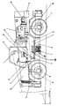
- the crane vehicle has a flexurally and torsionally rigid vehicle frame 10, on which wheels 11 are individually suspended in pairs.
- a nominal load of 35/40 t the vehicle shown only has two pairs of wheels in order to ensure the desired short overall length.
- the wheels 11 can be steered at least in part with the aid of a steering device which has a divisible steering spindle 6.
- This divisible steering spindle can be hydraulically unlocked and locked and ensures that there is mechanical steering intervention when the crane vehicle is moving at speeds of more than 62 km / h on public roads (motorways).
- a turntable 12 which can be pivoted horizontally on the vehicle frame 10, is provided, the axis of rotation of which, not shown, is arranged in the region of a rotary feedthrough 2 for the wheel drives to be described later.
- a combined travel and crane motor 1 is provided in the rear area of the rotary table 12 above the rear half of the vehicle frame, i.e. essentially above the rear pair of wheels.
- This drive motor for driving operation and for crane operation is preferably designed as a diesel machine and drives a driving pump 1a for hydraulic oil. Through hoses, not shown, the hydraulic oil passes from the drive pump 1a to the rotary feedthrough 2 and from there to the hydrostatic wheel drives 3.
- the hydrostatic wheel drives are supplied with hydraulic oil either by spring cylinders 16 assigned to each wheel 11 or by the wheel suspension of the driven ones, not shown in detail Vehicle wheels.
- the rotary feedthrough 2 is provided in the vehicle frame 10, which is cut out at this point, but is of sufficiently strong construction.
- the rotating union 2 is located exactly in the middle with respect to the ball slewing ring 7, which represents the connection between the vehicle frame 10 and the rotary table 12.
- the rotary feedthrough 2 basically consists of two parts that can rotate against one another, one of these parts being fastened to the vehicle frame 10 and the other rotatable part being carried along by the turntable 12.
- the first assembly of the rotating union 2, which is firmly connected to the vehicle frame 10, is shown in hatched lines (hatching from bottom left to top right), whereas the second assembly of the rotating union, which is non-rotatably connected to the rotary table 12, is shown in the drawing hatched (hatching from top left to bottom right) is shown.
- oil supply channels are formed which are connected at their upper ends to hydraulic oil inlets, three of which are shown schematically in the drawing, designated by the reference number 18. These oil supply channels each open into an annular channel that is open to the adjacent component of the first assembly, which is fixed to the frame. Hydraulic oil supply lines, which are formed in the frame-fixed parts and through which the oil flows from the respective ring channels to the outer surface of the frame-fixed assembly, open into these ring channels (of the rotatable assembly).
- a telescopic crane mast 13 Connected to the turntable 12 and articulated on it in a vertically pivotable manner is a telescopic crane mast 13 which, in the exemplary embodiment shown, has a base mast and seven telescopic parts which can be pushed in and out.
- the crane mast 13 is raised with the aid of a luffing cylinder 8 from its rest and transport position shown in the drawing into its working position (not shown).
- the travel and crane motor 1 With its not inconsiderable weight, the travel and crane motor 1 also acts as a counterweight for the crane mast 13.
- the mass of the counterweight prescribed in accordance with the specifications of the crane vehicle manufacturers, which is arranged in or on the turntable 12, can thus be about the mass of the travel and Crane motor 1 are reduced, whereby the total weight of the crane vehicle is reduced by the weight of the driving and crane motor 1. If the travel and crane motor 1 were not arranged in the turntable 12, an additional counterweight carried along for the crane operation would have to be made heavier by the weight of the motor device 1.
- the crane vehicle has a driver's cabin 14 arranged in front of the driving and crane motor 1 with the driver's seat 15 arranged therein.
- the vehicle frame 10 is essentially lowered to the height of the center points of the wheels 11, at least some of the wheels being provided with the above-mentioned hydrostatic individual drives 3, which in turn are arranged in the region of the hubs of the driven wheels 11.
- the driver's cab 14 can be bolted to the undercarriage while driving, which essentially takes place together with the hydraulic locking of the split steering spindle 6, in order to ensure the mechanical steering intervention required by road traffic approval when driving speeds of more than 62 km / h are reached.
- the front end of the crane mast 13 can be placed on the lowered vehicle frame 10. Furthermore, the crane mast has such a short base mast length that the crane mast length essentially corresponds to the length of the vehicle frame.
- the driver has an unrestricted all-round view in the travel position of the crane vehicle within the radius of vision radius of a maximum of 12 m required by the road traffic approval regulations.
- This unrestricted all-round view for the driver is all the more noteworthy since it was not achieved by increasing the driver's position, but despite the realization of a surprisingly low vehicle height.
- An additional counterweight 5 for crane operation can be placed in driving operation in the front area of the crane vehicle, preferably on the front end section of the vehicle frame 10.
- the additional counterweight 5 can be arranged at the rear end of the turntable 12, as shown in dash-dotted lines in the drawing. If, as discussed above, the travel and crane motor 1 were not arranged in the turntable 12, the additional counterweight 5 would have to be made heavier by the weight of the motor 1 in order to apply the counterweights required according to the usual crane tables.
- the driver's cabin 14 has a removable upper part in order to be able to reduce the overall height of the crane vehicle if necessary. Furthermore, the driver's seat 15 provided in the driver's cabin can be deflected to such an extent that the driver's head can be moved below the highest vehicle edge 17.
- the hydraulic oil is supplied to the hydrostatic wheel drives 3 - as already mentioned - via the rotary union 2.
- the hydraulic oil is supplied to the respective driven vehicle wheels 11 either through the spring cylinders 16 assigned to each wheel or through the wheel suspension assigned to each wheel if no spring cylinders are provided.
Applications Claiming Priority (2)
| Application Number | Priority Date | Filing Date | Title |
|---|---|---|---|
| DE9302376U DE9302376U1 (fr) | 1993-02-18 | 1993-02-18 | |
| DE9302376U | 1993-02-18 |
Publications (2)
| Publication Number | Publication Date |
|---|---|
| EP0611725A1 true EP0611725A1 (fr) | 1994-08-24 |
| EP0611725B1 EP0611725B1 (fr) | 1996-12-27 |
Family
ID=6889583
Family Applications (1)
| Application Number | Title | Priority Date | Filing Date |
|---|---|---|---|
| EP94102435A Expired - Lifetime EP0611725B1 (fr) | 1993-02-18 | 1994-02-17 | Grue montée sur un vehicule |
Country Status (5)
| Country | Link |
|---|---|
| US (1) | US5405028A (fr) |
| EP (1) | EP0611725B1 (fr) |
| JP (1) | JP2753799B2 (fr) |
| AT (1) | ATE146759T1 (fr) |
| DE (2) | DE9302376U1 (fr) |
Cited By (3)
| Publication number | Priority date | Publication date | Assignee | Title |
|---|---|---|---|---|
| DE19603966A1 (de) * | 1996-01-26 | 1997-07-31 | Kirow Leipzig Rail & Port Ag M | Mobilkran |
| DE202008005033U1 (de) * | 2008-04-11 | 2009-08-20 | Liebherr-Werk Ehingen Gmbh | Mobilkran |
| EP2095987A1 (fr) * | 2008-02-26 | 2009-09-02 | Kobelco Cranes Co., Ltd. | Appareil de transmission de puissance pour véhicule de travail |
Families Citing this family (9)
| Publication number | Priority date | Publication date | Assignee | Title |
|---|---|---|---|---|
| JPH07242130A (ja) * | 1994-03-07 | 1995-09-19 | Komatsu Ltd | 作業用車両の走行駆動装置 |
| EP1008549A3 (fr) | 1998-12-09 | 2000-08-02 | Compact Truck AG | Grue montée sur un véhicule |
| DE19948831B4 (de) * | 1999-10-06 | 2005-06-30 | Terex-Demag Gmbh & Co. Kg | Fahrzeugkran |
| WO2003029126A1 (fr) * | 2001-09-28 | 2003-04-10 | Kobelco Construction Machinery Co., Ltd. | Machine de travail autotractee |
| DE102014004803A1 (de) | 2014-04-03 | 2015-10-08 | Tadano Faun Gmbh | Mobilkran |
| CN104091004B (zh) * | 2014-06-27 | 2017-09-22 | 北京工业大学 | 一种基于改进的粒子群算法的定量式静压转台优化设计方法 |
| DE202015002816U1 (de) | 2015-04-20 | 2016-04-21 | Steffen Kaspar | Antrieb für einen Kran |
| DE102016202365B3 (de) * | 2016-02-16 | 2017-07-13 | Tadano Faun Gmbh | Mobilkran |
| CN106430018B (zh) * | 2016-08-31 | 2021-04-16 | 浙江鼎力机械股份有限公司 | 具有低重心的车体及高空作业平台 |
Citations (14)
| Publication number | Priority date | Publication date | Assignee | Title |
|---|---|---|---|---|
| DE2142750A1 (de) * | 1971-08-26 | 1973-04-12 | Krupp Gmbh | Autokran |
| FR2181565A1 (fr) * | 1972-04-28 | 1973-12-07 | Haulotte Georges | |
| DE2300643A1 (de) * | 1973-01-08 | 1974-07-18 | Rheinstahl Ag | Fahrzeugkran |
| DE2455961A1 (de) * | 1974-11-27 | 1976-08-12 | Huet Aloysius T Van | Auf der ladeflaeche eines transportfahrzeuges laengsverfahrbarer kran |
| DE2837398A1 (de) * | 1978-08-26 | 1980-03-06 | Gottwald Kg Leo | Fahrzeugkran |
| GB2056407A (en) * | 1977-09-21 | 1981-03-18 | Jlg Ind Inc | Industrial cranes |
| GB2066430A (en) * | 1979-12-24 | 1981-07-08 | Linde Ag | Hydrostatic drive system for an excavator |
| GB2082984A (en) * | 1980-09-03 | 1982-03-17 | Coles Cranes Ltd | Chassis for platform vehicles |
| DE3640183A1 (de) * | 1986-01-27 | 1987-07-30 | Kobe Steel Ltd | Hydraulik-antriebssystem fuer einen gegenmassewagen eines gegenmassekrans |
| EP0325064A1 (fr) * | 1987-12-18 | 1989-07-26 | Manitou Bf | Amélioration à la stabilité des chariots élévateurs à bras télescopique |
| GB2218397A (en) * | 1988-05-12 | 1989-11-15 | Grove Coles Ltd | Telescopic boom crane |
| DE9001589U1 (fr) * | 1990-02-12 | 1990-06-13 | Liebherr-Werk Ehingen Gmbh, 7930 Ehingen, De | |
| US4984695A (en) * | 1989-09-14 | 1991-01-15 | Kabushiki Kaisha Kobe Seiko Sho | Wheel crane |
| EP0543276A1 (fr) * | 1991-11-21 | 1993-05-26 | Krupp Industrietechnik Gmbh | Grue mobile |
Family Cites Families (12)
| Publication number | Priority date | Publication date | Assignee | Title |
|---|---|---|---|---|
| US3249336A (en) * | 1963-06-18 | 1966-05-03 | Baldwin Lima Hamilton Corp | Hydraulic winch control mechanism |
| JPS4914805A (fr) * | 1972-06-05 | 1974-02-08 | ||
| GB1529302A (en) * | 1974-10-05 | 1978-10-18 | Coles Cranes Ltd | Steering arrangements for mobile cranes |
| GB1518798A (en) * | 1974-10-05 | 1978-07-26 | Coles Cranes Ltd | Rough terrain cranes (swingable cb) |
| US4189021A (en) * | 1976-10-26 | 1980-02-19 | Firma Johannes Fuchs | High-speed mobile working machine |
| US4177869A (en) * | 1978-04-21 | 1979-12-11 | Dresser Industries, Inc. | Swivel joint for a vehicle |
| JPS57186976A (en) * | 1981-05-08 | 1982-11-17 | Nippon Densan Kk | Brushless motor |
| JPS592071U (ja) * | 1982-06-28 | 1984-01-07 | 新神戸電機株式会社 | 蓄電池 |
| JPS6111336U (ja) * | 1984-06-25 | 1986-01-23 | 唯志 毛利 | 頭髪用ブラシ |
| JPS6137195A (ja) * | 1984-07-31 | 1986-02-22 | 蛇の目ミシン工業株式会社 | ミシンにおける糸巻安全装置 |
| JPH08665B2 (ja) * | 1986-07-12 | 1996-01-10 | 株式会社加藤製作所 | 特殊車両の運転室移動装置 |
| JPH0641360B2 (ja) * | 1991-02-08 | 1994-06-01 | 株式会社神戸製鋼所 | ホイールクレーン |
-
1993
- 1993-02-18 DE DE9302376U patent/DE9302376U1/de not_active Expired - Lifetime
-
1994
- 1994-02-10 US US08/194,355 patent/US5405028A/en not_active Expired - Fee Related
- 1994-02-17 EP EP94102435A patent/EP0611725B1/fr not_active Expired - Lifetime
- 1994-02-17 AT AT94102435T patent/ATE146759T1/de not_active IP Right Cessation
- 1994-02-17 DE DE59401359T patent/DE59401359D1/de not_active Expired - Fee Related
- 1994-02-17 JP JP6020320A patent/JP2753799B2/ja not_active Expired - Lifetime
Patent Citations (14)
| Publication number | Priority date | Publication date | Assignee | Title |
|---|---|---|---|---|
| DE2142750A1 (de) * | 1971-08-26 | 1973-04-12 | Krupp Gmbh | Autokran |
| FR2181565A1 (fr) * | 1972-04-28 | 1973-12-07 | Haulotte Georges | |
| DE2300643A1 (de) * | 1973-01-08 | 1974-07-18 | Rheinstahl Ag | Fahrzeugkran |
| DE2455961A1 (de) * | 1974-11-27 | 1976-08-12 | Huet Aloysius T Van | Auf der ladeflaeche eines transportfahrzeuges laengsverfahrbarer kran |
| GB2056407A (en) * | 1977-09-21 | 1981-03-18 | Jlg Ind Inc | Industrial cranes |
| DE2837398A1 (de) * | 1978-08-26 | 1980-03-06 | Gottwald Kg Leo | Fahrzeugkran |
| GB2066430A (en) * | 1979-12-24 | 1981-07-08 | Linde Ag | Hydrostatic drive system for an excavator |
| GB2082984A (en) * | 1980-09-03 | 1982-03-17 | Coles Cranes Ltd | Chassis for platform vehicles |
| DE3640183A1 (de) * | 1986-01-27 | 1987-07-30 | Kobe Steel Ltd | Hydraulik-antriebssystem fuer einen gegenmassewagen eines gegenmassekrans |
| EP0325064A1 (fr) * | 1987-12-18 | 1989-07-26 | Manitou Bf | Amélioration à la stabilité des chariots élévateurs à bras télescopique |
| GB2218397A (en) * | 1988-05-12 | 1989-11-15 | Grove Coles Ltd | Telescopic boom crane |
| US4984695A (en) * | 1989-09-14 | 1991-01-15 | Kabushiki Kaisha Kobe Seiko Sho | Wheel crane |
| DE9001589U1 (fr) * | 1990-02-12 | 1990-06-13 | Liebherr-Werk Ehingen Gmbh, 7930 Ehingen, De | |
| EP0543276A1 (fr) * | 1991-11-21 | 1993-05-26 | Krupp Industrietechnik Gmbh | Grue mobile |
Cited By (6)
| Publication number | Priority date | Publication date | Assignee | Title |
|---|---|---|---|---|
| DE19603966A1 (de) * | 1996-01-26 | 1997-07-31 | Kirow Leipzig Rail & Port Ag M | Mobilkran |
| WO1997027138A1 (fr) * | 1996-01-26 | 1997-07-31 | Maschinenbau Kirow Leipzig Rail & Port Ag | Grue mobile |
| EP2095987A1 (fr) * | 2008-02-26 | 2009-09-02 | Kobelco Cranes Co., Ltd. | Appareil de transmission de puissance pour véhicule de travail |
| DE202008005033U1 (de) * | 2008-04-11 | 2009-08-20 | Liebherr-Werk Ehingen Gmbh | Mobilkran |
| EP2119663A2 (fr) * | 2008-04-11 | 2009-11-18 | Liebherr-Werk Ehingen GmbH | Grue mobile avec bras de cabine télescopique |
| EP2119663B1 (fr) * | 2008-04-11 | 2013-05-15 | Liebherr-Werk Ehingen GmbH | Grue mobile avec bras de cabine télescopique |
Also Published As
| Publication number | Publication date |
|---|---|
| DE9302376U1 (fr) | 1993-06-24 |
| EP0611725B1 (fr) | 1996-12-27 |
| US5405028A (en) | 1995-04-11 |
| DE59401359D1 (de) | 1997-02-06 |
| JPH07137984A (ja) | 1995-05-30 |
| ATE146759T1 (de) | 1997-01-15 |
| JP2753799B2 (ja) | 1998-05-20 |
Similar Documents
| Publication | Publication Date | Title |
|---|---|---|
| EP0110415B1 (fr) | Petit engin de travaux divers | |
| EP0611725B1 (fr) | Grue montée sur un vehicule | |
| DE602005002020T2 (de) | Lenkachse für fahrzeuge, insbesondere für arbeitsmaschinen oder ackerschlepper | |
| DE3912194C2 (de) | Fahrzeug | |
| DE2544958A1 (de) | Selbstfahrende maschine fuer einsatz in hoch- und tiefbau | |
| DE3425838A1 (de) | Loeffelbagger | |
| EP1008549A2 (fr) | Grue montée sur un véhicule | |
| DE2840665A1 (de) | Industriekran | |
| WO1998005581A2 (fr) | Grue automotrice | |
| EP0446599B1 (fr) | Grue montée sur un véhicule | |
| DE3230220C2 (fr) | ||
| EP0814052A1 (fr) | Plate-forme de travail mobile | |
| DE2156282C3 (de) | Maschine zum schichtweisen Abtragen von verschlissenen Straßendecken | |
| EP0543276B1 (fr) | Grue mobile | |
| DE4220456C1 (de) | Schienenschleifmaschine | |
| EP0899173B1 (fr) | Véhicule avec chassis stabilisé | |
| DE2022427A1 (de) | Fahrzeug mit zwei Arbeitsgeraeten | |
| DE3406412A1 (de) | Bewegliche maschine, insbesondere kranfahrzeug | |
| DE102012001377A1 (de) | Ballastwagen für einen Derrickkran | |
| DE2905528A1 (de) | Achsschenkelgelenktes kraftfahrzeug | |
| DE3409515C2 (fr) | ||
| DE4217261A1 (de) | Antriebsanordnung, insbesondere für Omnibusse | |
| DE3230659C2 (de) | Selbstfahrende Arbeitsmaschine | |
| EP0514672A1 (fr) | Dispositif pour amortir respectivement commander la mise en portefeuille entre les véhicules partiels d'un véhicule articulé | |
| DE102006045995B4 (de) | Fahrantrieb insbesondere eines Universalfahrzeuges für Unterstützungssysteme |
Legal Events
| Date | Code | Title | Description |
|---|---|---|---|
| PUAI | Public reference made under article 153(3) epc to a published international application that has entered the european phase |
Free format text: ORIGINAL CODE: 0009012 |
|
| AK | Designated contracting states |
Kind code of ref document: A1 Designated state(s): AT BE CH DE DK ES FR GB IT LI LU MC NL PT SE |
|
| 17P | Request for examination filed |
Effective date: 19941223 |
|
| GRAG | Despatch of communication of intention to grant |
Free format text: ORIGINAL CODE: EPIDOS AGRA |
|
| 17Q | First examination report despatched |
Effective date: 19960212 |
|
| GRAH | Despatch of communication of intention to grant a patent |
Free format text: ORIGINAL CODE: EPIDOS IGRA |
|
| GRAH | Despatch of communication of intention to grant a patent |
Free format text: ORIGINAL CODE: EPIDOS IGRA |
|
| GRAA | (expected) grant |
Free format text: ORIGINAL CODE: 0009210 |
|
| AK | Designated contracting states |
Kind code of ref document: B1 Designated state(s): AT BE CH DE DK ES FR GB IT LI LU MC NL PT SE |
|
| PG25 | Lapsed in a contracting state [announced via postgrant information from national office to epo] |
Ref country code: NL Free format text: LAPSE BECAUSE OF FAILURE TO SUBMIT A TRANSLATION OF THE DESCRIPTION OR TO PAY THE FEE WITHIN THE PRESCRIBED TIME-LIMIT Effective date: 19961227 Ref country code: IT Free format text: LAPSE BECAUSE OF FAILURE TO SUBMIT A TRANSLATION OF THE DESCRIPTION OR TO PAY THE FEE WITHIN THE PRESCRIBED TIME-LIMIT;WARNING: LAPSES OF ITALIAN PATENTS WITH EFFECTIVE DATE BEFORE 2007 MAY HAVE OCCURRED AT ANY TIME BEFORE 2007. THE CORRECT EFFECTIVE DATE MAY BE DIFFERENT FROM THE ONE RECORDED. Effective date: 19961227 Ref country code: ES Free format text: THE PATENT HAS BEEN ANNULLED BY A DECISION OF A NATIONAL AUTHORITY Effective date: 19961227 Ref country code: DK Effective date: 19961227 |
|
| REF | Corresponds to: |
Ref document number: 146759 Country of ref document: AT Date of ref document: 19970115 Kind code of ref document: T |
|
| REF | Corresponds to: |
Ref document number: 59401359 Country of ref document: DE Date of ref document: 19970206 |
|
| PG25 | Lapsed in a contracting state [announced via postgrant information from national office to epo] |
Ref country code: AT Free format text: LAPSE BECAUSE OF NON-PAYMENT OF DUE FEES Effective date: 19970217 |
|
| GBT | Gb: translation of ep patent filed (gb section 77(6)(a)/1977) |
Effective date: 19970125 |
|
| PG25 | Lapsed in a contracting state [announced via postgrant information from national office to epo] |
Ref country code: LU Free format text: LAPSE BECAUSE OF NON-PAYMENT OF DUE FEES Effective date: 19970228 Ref country code: LI Effective date: 19970228 Ref country code: CH Effective date: 19970228 Ref country code: BE Effective date: 19970228 |
|
| PGFP | Annual fee paid to national office [announced via postgrant information from national office to epo] |
Ref country code: FR Payment date: 19970228 Year of fee payment: 4 |
|
| ET | Fr: translation filed | ||
| PG25 | Lapsed in a contracting state [announced via postgrant information from national office to epo] |
Ref country code: SE Effective date: 19970327 Ref country code: PT Effective date: 19970327 |
|
| NLV1 | Nl: lapsed or annulled due to failure to fulfill the requirements of art. 29p and 29m of the patents act | ||
| PG25 | Lapsed in a contracting state [announced via postgrant information from national office to epo] |
Ref country code: MC Effective date: 19970831 |
|
| PLBI | Opposition filed |
Free format text: ORIGINAL CODE: 0009260 |
|
| PLBQ | Unpublished change to opponent data |
Free format text: ORIGINAL CODE: EPIDOS OPPO |
|
| REG | Reference to a national code |
Ref country code: CH Ref legal event code: PL |
|
| PLBF | Reply of patent proprietor to notice(s) of opposition |
Free format text: ORIGINAL CODE: EPIDOS OBSO |
|
| 26 | Opposition filed |
Opponent name: DEUTSCHE GROVE GMBH Effective date: 19970926 |
|
| PG25 | Lapsed in a contracting state [announced via postgrant information from national office to epo] |
Ref country code: GB Free format text: LAPSE BECAUSE OF NON-PAYMENT OF DUE FEES Effective date: 19980217 |
|
| PG25 | Lapsed in a contracting state [announced via postgrant information from national office to epo] |
Ref country code: FR Free format text: THE PATENT HAS BEEN ANNULLED BY A DECISION OF A NATIONAL AUTHORITY Effective date: 19980228 |
|
| PLBF | Reply of patent proprietor to notice(s) of opposition |
Free format text: ORIGINAL CODE: EPIDOS OBSO |
|
| PLBF | Reply of patent proprietor to notice(s) of opposition |
Free format text: ORIGINAL CODE: EPIDOS OBSO |
|
| GBPC | Gb: european patent ceased through non-payment of renewal fee |
Effective date: 19980217 |
|
| REG | Reference to a national code |
Ref country code: FR Ref legal event code: ST |
|
| PLBL | Opposition procedure terminated |
Free format text: ORIGINAL CODE: EPIDOS OPPC |
|
| PLBM | Termination of opposition procedure: date of legal effect published |
Free format text: ORIGINAL CODE: 0009276 |
|
| STAA | Information on the status of an ep patent application or granted ep patent |
Free format text: STATUS: OPPOSITION PROCEDURE CLOSED |
|
| 27C | Opposition proceedings terminated |
Effective date: 19991128 |
|
| PGFP | Annual fee paid to national office [announced via postgrant information from national office to epo] |
Ref country code: DE Payment date: 20020328 Year of fee payment: 9 |
|
| PG25 | Lapsed in a contracting state [announced via postgrant information from national office to epo] |
Ref country code: DE Free format text: LAPSE BECAUSE OF NON-PAYMENT OF DUE FEES Effective date: 20030902 |