EP0606490B1 - Procede d'impression par jet d'encre du type a transfert intermediaire - Google Patents
Procede d'impression par jet d'encre du type a transfert intermediaire Download PDFInfo
- Publication number
- EP0606490B1 EP0606490B1 EP93914949A EP93914949A EP0606490B1 EP 0606490 B1 EP0606490 B1 EP 0606490B1 EP 93914949 A EP93914949 A EP 93914949A EP 93914949 A EP93914949 A EP 93914949A EP 0606490 B1 EP0606490 B1 EP 0606490B1
- Authority
- EP
- European Patent Office
- Prior art keywords
- ink
- water
- thermoplastic resin
- image
- jet recording
- Prior art date
- Legal status (The legal status is an assumption and is not a legal conclusion. Google has not performed a legal analysis and makes no representation as to the accuracy of the status listed.)
- Expired - Lifetime
Links
Images


Classifications
-
- C—CHEMISTRY; METALLURGY
- C09—DYES; PAINTS; POLISHES; NATURAL RESINS; ADHESIVES; COMPOSITIONS NOT OTHERWISE PROVIDED FOR; APPLICATIONS OF MATERIALS NOT OTHERWISE PROVIDED FOR
- C09D—COATING COMPOSITIONS, e.g. PAINTS, VARNISHES OR LACQUERS; FILLING PASTES; CHEMICAL PAINT OR INK REMOVERS; INKS; CORRECTING FLUIDS; WOODSTAINS; PASTES OR SOLIDS FOR COLOURING OR PRINTING; USE OF MATERIALS THEREFOR
- C09D11/00—Inks
- C09D11/30—Inkjet printing inks
-
- B—PERFORMING OPERATIONS; TRANSPORTING
- B41—PRINTING; LINING MACHINES; TYPEWRITERS; STAMPS
- B41J—TYPEWRITERS; SELECTIVE PRINTING MECHANISMS, i.e. MECHANISMS PRINTING OTHERWISE THAN FROM A FORME; CORRECTION OF TYPOGRAPHICAL ERRORS
- B41J2/00—Typewriters or selective printing mechanisms characterised by the printing or marking process for which they are designed
- B41J2/005—Typewriters or selective printing mechanisms characterised by the printing or marking process for which they are designed characterised by bringing liquid or particles selectively into contact with a printing material
- B41J2/0057—Typewriters or selective printing mechanisms characterised by the printing or marking process for which they are designed characterised by bringing liquid or particles selectively into contact with a printing material where an intermediate transfer member receives the ink before transferring it on the printing material
-
- B—PERFORMING OPERATIONS; TRANSPORTING
- B41—PRINTING; LINING MACHINES; TYPEWRITERS; STAMPS
- B41M—PRINTING, DUPLICATING, MARKING, OR COPYING PROCESSES; COLOUR PRINTING
- B41M5/00—Duplicating or marking methods; Sheet materials for use therein
- B41M5/025—Duplicating or marking methods; Sheet materials for use therein by transferring ink from the master sheet
- B41M5/0256—Duplicating or marking methods; Sheet materials for use therein by transferring ink from the master sheet the transferable ink pattern being obtained by means of a computer driven printer, e.g. an ink jet or laser printer, or by electrographic means
-
- B—PERFORMING OPERATIONS; TRANSPORTING
- B41—PRINTING; LINING MACHINES; TYPEWRITERS; STAMPS
- B41M—PRINTING, DUPLICATING, MARKING, OR COPYING PROCESSES; COLOUR PRINTING
- B41M7/00—After-treatment of prints, e.g. heating, irradiating, setting of the ink, protection of the printed stock
- B41M7/009—After-treatment of prints, e.g. heating, irradiating, setting of the ink, protection of the printed stock using thermal means, e.g. infrared radiation, heat
-
- B—PERFORMING OPERATIONS; TRANSPORTING
- B41—PRINTING; LINING MACHINES; TYPEWRITERS; STAMPS
- B41J—TYPEWRITERS; SELECTIVE PRINTING MECHANISMS, i.e. MECHANISMS PRINTING OTHERWISE THAN FROM A FORME; CORRECTION OF TYPOGRAPHICAL ERRORS
- B41J2/00—Typewriters or selective printing mechanisms characterised by the printing or marking process for which they are designed
- B41J2/005—Typewriters or selective printing mechanisms characterised by the printing or marking process for which they are designed characterised by bringing liquid or particles selectively into contact with a printing material
- B41J2/01—Ink jet
- B41J2/17—Ink jet characterised by ink handling
- B41J2/175—Ink supply systems ; Circuit parts therefor
- B41J2/17593—Supplying ink in a solid state
Definitions
- the present invention relates to an ink composition for use in an intermediate transfer ink jet recording device and an intermediate transfer ink jet recording method and an intermediate transfer ink jet recording device using the ink composition.
- An ink jet recording system is advantageously excellent in the simplicity of the mechanism and noiseless.
- This type of printing has problems including that the quality of prints varies depending upon recording media (for example, depending upon properties of recording paper) and also including that the image of a portion remaining undried of an ink image is disturbed when the recording medium is discharged.
- a proposal has been made on a method called an "intermediate transfer system" wherein an ink image is once formed on a transfer medium by an ink jet recording process and then transferred to a recording medium (Japanese Patent Laid-Open No. 225958/1984 and U.S. Patent No. 4,538,156).
- a recording head can be disposed apart from the recording paper.
- this method successfully prevents the recording head from clogging which is due to the possibility that the recording head contacts with the recording paper since they are disposed closely or that paper lint from the recording paper is attached to the recording head.
- the intermediate transfer ink jet recording method there is room for an improvement in the quality of the image transferred on the recording medium.
- Japanese Patent Laid-Open Nos. 92849/1987, 169643/1991 and 284948/1991 and U.S. Patent No. 5099256 propose a method which comprises the steps of ejecting ink droplets on a transfer medium to form an ink image, evaporating a large proportion of water in the ink image to dehydrate the ink image to a substantially dry state and transferring the concentrated ink to recording paper.
- this transfer ink jet recording method however, high pressure is necessary for transferring the ink image to the recording medium, since the bonding force between the recording medium and the ink image is small.
- the provision of means for applying necessary pressure renders the recording device complicated.
- EP-A-0 571 190 which partially belongs to the prior art according to Article 54(3), discloses ink compositions for ink jet printing, which comprise (a) a pigment, (b) a component selected from the group consisting of saccharides, derivatives thereof and polyols having 5 or more hydroxyl groups, and (c) a resin emulsion.
- JP-A 60-76343 discloses an ink jet recording device comprising an intermediate transfer medium; recording means for ejecting droplets to form an ink image on the intermediate transfer medium; first heating means for concentrating the image formed on the intermediate transfer medium; transfer means for pressing the ink image on the intermediate transfer medium against a recording medium to transfer the image to the recording medium; and second heating means to transfer the ink to the recording medium.
- an object of the present invention is to provide an ink composition for intermediate transfer ink jet recording that enables an excellent quality and a good fixing strength of prints to be attained independently of a recording medium used.
- Another object of the present invention is to provide an ink composition for intermediate transfer ink jet recording that is free from the clogging of the ink jet recording head and can simplify the transfer and fixing operation.
- a further object of the present invention is to provide an intermediate transfer ink jet recording method using the above ink composition for ink jet recording, which method enables an excellent quality and a good fixing strength of prints to be attained independently of a recording medium used.
- a further object of the present invention is to provide an intermediate transfer ink jet recording method that enables a good ink image to be transferred from an intermediate transfer medium to a recording medium under low pressure.
- a further object of the present invention is to provide an intermediate transfer ink jet recording device suitable for an ink jet recording method using the above ink composition.
- the intermediate transfer ink jet recording method comprises the steps of:
- the intermediate transfer ink jet recording method comprises the steps of:
- the ink composition for use in the intermediate transfer ink jet recording method according to the first aspect of the present invention comprises water, a thermoplastic resin, a colorant and a water-soluble organic solvent.
- the ink composition for use in the intermediate transfer ink jet recording method according to the second aspect of the present invention comprises water, a thermoplastic resin, a colorant and a water-soluble organic solvent and, when the thermoplastic resin is a water-insoluble resin, further comprises a water-soluble polymer.
- the first intermediate transfer ink jet recording device used in the method according to the first aspect of the present invention comprises:
- the second intermediate transfer ink jet recording device used in the method according to the second aspect of the present invention comprises:
- an ink composition comprising water, a colorant, a thermoplastic resin and a water-soluble organic solvent is employed (This method is hereinafter often referred to as “recording method A”.
- the device used for practicing this method is hereinafter referred to as “recording device A”).
- an ink composition comprising water, a colorant, a thermoplastic resin and a water-soluble organic solvent and, when the thermoplastic resin is a water-insoluble resin, further comprising a water-soluble polymer is employed (This method being hereinafter often referred to as “recording method B”.
- the device used for practicing this method is hereinafter referred to as “recording device B").
- Fig. 1 is a perspective view of a device for the recording method A according to the present invention.
- Fig. 2 is a cross-sectional view in the direction of X of the device shown in Fig. 1.
- This device comprises a transfer drum 1 as an intermediate transfer medium and ink jet recording means 2 and a pressure roller 3 which are disposed around the transfer drum 1 from the upstream side in the direction of rotation of the transfer drum 1.
- the transfer drum 1 comprises an elastic layer 11 constituting the surface of the drum 1 and an internal drum 12.
- a recording medium 4 is sandwiched and supported between the transfer drum 1 and the pressure roller 3, and carried with the rotation of the recording drum 1 and the pressure roller 3.
- the transfer drum 1 is heated by a heater 5 which is heating means provided inside the transfer drum 1.
- the heater 7 heats the surface of the transfer drum 1 to at least the softening or melting temperature of the thermoplastic resin contained in the ink so that the ink image can be transferred in the following manner. (The transfer in the following manner is hereinafter often referred to as "interfacial transfer".
- the ink image ready for the interfacial transfer is hereinafter often referred to as an ink image "brought to a film form”.
- the pressure roller 3 can press the recording medium 6 against the transfer drum 1 by taking advantage of the pressure applied by pressurizing means 30. If necessary, the pressing of the pressure roller 3 against the recording medium 4 can be released by pressure release means 31. Furthermore, if necessary, cleaning means 7 for removing a remaining ink or the like after the transfer of the ink image may be provided downstream of the pressure roller 3.
- printing is effected as follows.
- recording means 2 an ink jet recording head
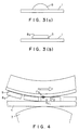
- the ink image 8 immediately after formed can take a form as shown in Fig. 3(a).
- the ink image 8 is heated on the transfer drum 1 by the heater 5.
- the heating causes the solvent to be evaporated from the ink image 8.
- This increases the solid component concentration.
- an agglomerate consisting essentially of solid components is formed on the transfer drum 1.
- the agglomerate is heated on the transfer drum 1 to at least the softening or melting temperature of the thermoplastic resin contained in the ink, particles constituting the agglomerate of solid components are softened or melted.
- a layer 9 of a water-soluble organic solvent (hereinafter often referred to as a "peeling layer”) is formed between the ink image 8a and the transfer drum 1 with forming the ink image 8a.
- a peeling layer is formed between the ink image 8a and the transfer drum 1 with forming the ink image 8a.
- the ink image 8a in the heated state is carried to a region facing the pressure roller 3 with the rotation of the transfer drum 1 and then transferred to the recording medium 4.
- the transfer drum 1 is pressed through the recording medium 4 against the pressure roller 3.
- three forces that is, an adhesive force (F1) between the ink image 8a and the recording medium 4, a cohesive force (F2) of the ink image 8a and an adhesive force (F3) between the ink image 8a and the surface of the transfer roller 1 have the relationship F1 > F2 > F3.
- one interface of the ink image 8a is wholly peeled off from the surface of the transfer drum 1 whereas the other interface of the ink image is wholly adhered to the recording medium 4.
- the presence of the layer 9 of the organic solvent is advantageous because the F3 value becomes smaller.
- the ink image 8a is peeled and adhered at its interface, so that the untransferred remaining image can be effectively prevented.
- the ink composition may further comprises a saccharide.
- the saccharide serves to bind the solid component in the ink image to increase the cohesive force F2 and, at the same time, to increase the adhesive force F1 when the ink image has been brought to a film form.
- stable cohesive force F2 which stabilizes the ink image can be obtained independently of the printing pattern, so that not only good transfer and printing can be effected but also the ink image can be transferred from the transfer drum to the transfer medium under low pressure.
- the saccharide serves to stably impart the increased adhesive force to the ink image for a long period of time. Therefore, the time taken from the formation of the ink image to the transfer of the ink image can be advantageously set at will.
- a further great advantage of the present invention is that a thickness of about 2 to 10 ⁇ m suffices as the thickness of the ink image brought to a film form on the transfer drum for finally obtaining a sufficient image density (for example, 1.4 or more of the OD value) on the recording medium 4.
- the pressure applied in the transfer of the ink image to the recording medium is so high that the ink image is unfavorably deformed (that is, defaced), which causes the deterioration in the quality of the image.
- the thickness of the ink image on the transfer drum 1 is about 2 to 10 ⁇ m, that is, sufficiently smaller than 120 ⁇ m which is the diameter of one dot as the minimum pixel in 300 dpi recording. Therefore, the present invention is advantageous also in that the deformation of the ink image is so small that no defacing of the image is observed in the transfer of the image to the recording medium.
- good transfer can be effected independently of the kind of the recording medium, more specifically, independently of the surface profile of the recording paper.
- the ink image 8a can be transferred in "one" onto the recording medium 4 since the ink image 8a brought to a film form has a certain cohesive force F2.
- the recording medium is significantly uneven (for example, bond paper)
- the ink image 8a can be transferred with maintaining its shape because the ink image 8a can be adhered to the recording medium with an adhesive force attained merely by the contact of the ink image 8a with protrusions of the recording medium. Therefore, good transfer can be provided as no deficiency of the image attributable to the uneven surface of the recording medium occurs.
- the ink image 8a transferred to the recording medium 4 is not heated any more and then solidified. Even after the solidification, the adhesive force F1 of the ink image 8a remains still large, so that a good fixation of the ink image can be provided.
- ink image used herein is intended to mean both an image consisting of one dot as the minimum pixel alone and an image comprising a gathering of a plurality of dots adjacent and connected to each other.
- Fig. 5 is a schematic cross-sectional view of a device for the recording method B according to the present invention.
- Fig. 6 is a cross-sectional view in the direction of X of the device shown in Fig. 5.
- the some parts of this device is the same as that of the device shown in Fig. 1.
- Figs. 5 and 6 the parts common to Figs. 5 and 6 and Fig. 1 are indicated with the same reference numerals.
- the difference of the devices shown in Figs. 5 and 6 from the device shown in Fig. 1 is, firstly, that a heat 5 "concentrates" the ink image formed on the transfer drum 1 in such a manner that the ink image can be transferred by the interfacial transfer.
- this device is further provided with heating means 9.
- the heating means 9 comprises a roller 9b internally having a heating element 9a and a roller 9c facing the roller 9a with a recording medium between the rollers 9b and 9c.
- the heating means 9 is constructed so that the surface of the recording medium is heated to at least the softening or melting temperature of the thermoplastic resin contained in the ink.
- Printing is performed as follows. Firstly, recording means 2 ejects droplets of the ink composition onto the transfer drum 1 to form an ink image 8 on the transfer drum.
- the ink image 8 can take a form as shown in Fig. 3(a) as the recording method A.
- the formed ink image 8 is heated on the transfer drum 1 by the heating means 5.
- the heating causes the solvent to be evaporated from the ink image 8.
- the heating is effected in such a manner that the thermoplastic resin contained in the ink composition is neither softened nor melted.
- the heating in this recording method and the heating in the recording method A are common to evaporation of most water in the ink image to enhance the solid component concentration.
- this recording method is different from the recording method A in that the thermoplastic resin contained in the ink composition is neither softened nor melted. The heating increases the solid component concentration.
- an agglomerate consisting of solid components is formed on the transfer drum 1.
- the agglomerate has a cohesive force considered attributable to the water-soluble thermoplastic resin or the water-soluble polymer incorporated when the thermoplastic resin is a water-insoluble resin.
- This cohesive force brings the ink image to an ink image 8a in a film form having a substantially homogeneous thickness as shown in Fig. 3(b).
- the surface of the ink image 8a is viscous in the heated state.
- the concentrated ink image can be transferred to the recording medium by the interfacial transfer.
- the ink image in this state is often called an ink image "brought to a film form".
- the way of the "concentration” is not limited to any specific embodiment so far as, as described above, it serves to increase the solid component concentration of the ink image while preventing the softening or melting the thermoplastic resin.
- it is preferred to use any one of a method where a large amount of energy is applied in a short time to evaporate the solvent for example, heating is effected at a temperature of 100°C or above in a short time
- a method where heating is effected at a low temperature for example, at a temperature of 100°C or below
- the ink composition used in this method contains a water-soluble polymer even when the thermoplastic resin is a water-soluble resin.
- the agglomerate, i.e., the ink image 8 brought to a film form is conveyed to a region facing the pressure roller 3 with the rotation of the transfer drum 1 and then transferred to the recording medium 4.
- the three forces, i.e., the adhesive force (F1) between the ink image 8 and the recording medium 4, the cohesive force (F2) of the ink image 8 and the adhesive force (F3) between the ink image 8 and the surface of the transfer roller 1 have the relationship F1 > F2 > F3, so that the ink image can be transferred by the interfacial transfer.
- the ink composition contains a water-soluble organic solvent, and an organic solvent layer 9 is formed.
- F3 becomes smaller, which is advantageous for the interfacial transfer.
- an ink composition containing a saccharide may be employed. This enables the recording method B to enjoy the advantage as described in connection with the recording method A.
- the ink image transferred to the recording medium is then heated by the heating means 9. Since the heating temperature is at least the softening or melting temperature of the thermoplastic resin contained in the ink, particles constituting the agglomerate of solid components are softened or melted and mutually dissolved in one another to form a homogeneous ink image in a film form. As a result, improvements in cohesive force within the ink image and also in adhesion to the recording medium can be attained, so that a good print quality can be realized.
- a thickness of about 2 to 10 ⁇ m suffices as the thickness of the ink image brought to a film form on the transfer drum for finally obtaining a sufficient image density (for example, 1.4 or more of the OD value) on the recording medium 4. Therefore, recording method B also can enjoy the advantage that a deterioration in the image due to defacing of the image is hardly observed.
- the elastic layer 11 of the transfer drum 1 preferably comprises a rubber material, particularly preferably comprises a material that permits an ink image to be easily peeled off therefrom and is heat-resistant.
- the rubber material include a chloroprene rubber, a nitrile rubber, an ethylene/propylene rubber, a silicone rubber, a fluorosilicone rubber, a fluororubber, a natural rubber, a styrene rubber, an isoprene rubber, a butadiene rubber, an ethylene/propylene/butadiene polymer and a nitrile/butadiene rubber.
- a silicone rubber, a fluorosilicone rubber and a fluororubber are preferred from the viewpoint of heat resistance.
- the ink ejected as an ink droplet forms an ink image 8 on the transfer drum 1. If the ink image 8 is repelled or flows on the transfer drum, no desired ink image (for example, having a desired dot diameter) can be realized. In order to prevent this unfavorable phenomenon, it is preferred to use an ink composition adjusted to have a suitable capability of wetting the surface of the transfer drum by adding a surfactant.
- the image on the transfer drum 1 is formed with the ink jet recording means 2.
- the recording means 2 include an ink jet recording head using a piezoelectric element.
- An image on the transfer drum 1 with this recording head 2 can be formed by using various methods.
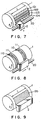
- the formation of the image by using the transfer drum 1 and the recording head 2 shown in Fig. 1 will now be described as an example with reference to Fig. 7.
- scanning is performed in the direction of arrow Y along a carriage shaft 20 parallel to the shaft of the transfer drum 1.
- the recording head 2 reciprocates along the carriage shaft, the head effects printing when it is in a printing region L except that the printing is suspended when the recording head 2 is outside the region L.
- the rotation of the transfer drum 1 is suspended when the recording head 2 is in the region L.
- the transfer drum 1 is rotated in the direction of A shown in the Figure at a given angle when the recording head 2 is outside the region L.
- the repetition of the reciprocated scanning of the recording head 2 with the intermittent rotation of the transfer drum 1 causes a region having an image formed on the transfer drum 1 to be increased as a striped region. As shown Fig. 7, striped regions 101, 102, 103 and 104 are successively formed.
- the recording head 2 is moved at a given rate along the carriage shaft 20 parallel to the shaft of the transfer drum 1 while rotating the transfer drum 1 at a given rate. As a result, regions 110, 111 printed on the transfer drum 1 are increased in a spiral form.
- the recording head 2 has two ink jet recording heads.
- a recording head 2 all over the printing region L is employed.
- the recording head 2 is fixed.
- the transfer drum 1 is rotated at a given rate, which causes a printing region 120 to be continuously increased in the circumferential direction of the transfer drum.
- the transfer of the ink image onto the recording medium should be effected after one page of an ink image is formed on the transfer drum 1.
- the transfer of the ink image onto the recording medium may be effected after one page of an ink image is formed on the transfer drum 1 (provided that the circumferential length of the transfer drum 1 is sufficient to record one page of ink image), or alternatively the transfer may be effected in the course of the formation of one page of the ink image.
- a device shown in Fig. 7 i.e., a device shown in Fig.
- the pressure roller 3 is aparted from the transfer drum 1 by the pressure release means 31 (the recording medium 4 as well remaining uncarried yet) until one page of the ink image is formed on the transfer drum 1.
- the pressure roller 3 is pressed against the transfer drum 1 by the pressurizing means 30.
- the recording medium 4 is carried to transfer the ink image onto the recording medium 4.
- the process is performed as follows. Specifically, the pressure roller 3 is previously pressed against the transfer drum 1 by the pressurizing means 30. The ink image brought to a film form by heating is continuously transferred to the recording medium 4 before one page of the ink image is completely formed.
- the heater 5 heats the surface of the transfer drum 1 to at least the softening or melting temperature of the thermoplastic resin contained in the ink composition so that the ink image can be brought to a film form.
- the heating temperature may be arbitrarily determined by taking the recording conditions such as the ink image forming method into consideration.
- the softening or melting temperature is between 50°C and 150°C, the image is heated in such a manner that the temperature is at least the softening or melting temperature of the thermoplastic resin and preferably in the range of from 50 to 200°C, still preferably in the range of from 50 to 180°C.
- heating means may be arbitrarily selected, preferred examples of the heating means include a combination of a heater lamp with a reflecting mirror.
- the heater 5 may be provided outside the transfer drum 1 but not inside the transfer drum 1.
- This embodiment is advantageous in that the ink image alone can be directly heated and reduce the heat conduction to the portion other than the ink image, for example, recording head 2.
- the warm up time taken for reaching a desired temperature in the transfer drum 1 can be shortened.
- the transfer drum may be provided integrally with the heating means.
- a heater layer 14 (for example, a ceramic heater) is provided on the insulating layer 13 which is provided on an internal drum 12.
- the elastic layer 11 is provided on the heater layer 14. The surface of the transfer drum is heated by the heater layer 14.
- the heater 5 is constructed integrally with the pressure roller 3 as shown in Fig. 12.
- heating means 5 for example, a heater
- printing is effected as follows.
- the pressure roller 3 is first provided somewhat apart from the transfer drum 1 by the pressure release means 31.
- the transfer drum 1 is heated to a desired temperature by the heater 5 provided inside the pressure roller 3.
- the ink image 8 formed by the recording head 2 is heated and brought to a film form by the heater 5.
- the pressure roller 3 is pressed against the transfer drum 1 by the pressurizing means 30.
- the recording medium 4 is carried to transfer the ink image to the recording medium.
- the pressure roller 3 may be pressed against the transfer drum 1 to heat the transfer drum 1.
- a series of procedures comprising the formation or an ink image, the conversion of the ink image to a film form and the transfer of the ink image in a film form to the recording medium may be performed in a continuous manner.
- the ink image formed by the recording head 2 is heated while pressed between the pressure roller 3 and the transfer drum 1 against the recording medium 4 to bring the ink image to a film form and transfer the ink image to the recording drum.
- a recording device as shown in Fig. 13.
- Fig. 14 is a partially perspective view of the device shown in Fig. 13.
- the device shown in Fig. 13 comprises the elements shown in Fig. 12 and further several elements.
- This device is provided with a carrier guide 40 and a carrier roller 41 that serve to carry the recording medium 4 also after pressing means of the pressure roller 3 with the recording medium in contact with or in close vicinity to the transfer drum 1.
- the carrier roller 41 is pressed by pressure applying means 42 and is separated from the transfer drum 1 by pressure release means 43.
- the carrier guide 40 is provided with a notch window 50. Air is sent to the notch window 50 with a cooling fan 44 to cool the recording medium 6 from the reverse of the print face.
- This device is further provided with means for cooling the recording medium having a transferred ink image, that is a cooling roller 45.
- the cooling roller 45 may comprise a metal having a good heat conductivity or a hollow roller filled with a cooling medium.
- the cooling roller 45 can be also pressed by the pressure applying means 46 and aparted from the transfer drum 1 by the pressure release means 47.
- printing is effected as follows. Specifically, as described above with reference to Fig. 12, firstly, the ink image formed on the transfer drum 1 by the recording head 2 is heated between the pressure roller 3 and the transfer drum 1 while the ink image is pressed against the recording medium 4, so that the ink image is brought to a film form and simultaneously transferred to the recording medium 4.
- the recording medium 4 is carried with the rotation of the transfer drum 1.
- the recording medium 4 is carried in contact with or in close vicinity to the transfer drum 1 by the carrier guide 40 and the carrier roller 41.
- the recording medium 4 is cooled by air sent from the cooling fan 44.
- the recording medium 4 is cooled with a cooling roller 45 and finally separated from the transfer drum 1 by a peeling claw 48.
- the ink image on the transfer drum to the recording medium can be successfully transferred under a low pressure of about 11.8 kN/m (12 kg/cm) or less, preferably about 9.8 kN/m (10 kg/cm).
- a low pressure of about 11.8 kN/m (12 kg/cm) or less, preferably about 9.8 kN/m (10 kg/cm).
- good transfer can be realized under a lower pressure than the above, specifically a pressure of about 9.8 kN/m (10 kg/cm) or less, preferably about 0.59 kN/m (0.6 kg/cm) or less.
- a pressure of 0.59 kN/m (0.6 kg/cm) or less is very advantageous from a reduction in size of the device and a reduction in cost of parts used.
- the recording device B for the recording method B will now be described. As described above, some parts of the recording device B are the same as that of the recording device A. Specifically, in the recording device B, the transfer drum 1, the recording head 2, the pressure roller 3, the heating means 5 and the cleaner means 7 may be the same as those described above in connection with the recording device A. Therefore, also in the devices shown in Figs. 5 and 6, these parts may be the same as those of the device shown in Figs. 1 and 2. Furthermore, the embodiments shown in Figs. 7 to 11 can be also utilized in the recording device B.
- the recording device B of the present invention and the recording device A are different from each other in that the recording device B has heating means that can sufficiently concentrate the ink image on the transfer drum 1 with the thermoplastic resin remaining unsoftened or unmelted. Thereafter, the ink image which has been concentrated and brought to a film form by heating is then transferred to the recording medium 4.
- the recording device B of the present invention has means for heating the ink image transferred to the recording medium 4 to at least the softening or melting temperature of the thermoplastic resin, i.e., post-heating means.
- the softening or melting temperature is between 50°C and 150°C
- the post heating is effected in such a manner that the heating temperature is at least the softening or melting temperature of the thermoplastic resin and preferably in the range of from 50 to 200°C, still preferably in the range of from 50 to 180°C.
- the roller 9b and the roller 9c comprise, for example, a metal having a good heat conductivity.
- the heating element in the post-heating means may be constructed, for example, as shown in Fig. 15. Specifically, the recording medium 4 having a transferred image is heated in a non-contact system with radiant heat from heating means 5 comprising a heater 52 and a reflecting mirror 53.
- the ink image can be successfully transferred from the transfer drum to the recording medium under a low pressure of about 14.7 kN/m (15 kg/cm) or less, preferably 9.8 kN/m (10 kg/cm) or less. Furthermore, when an ink composition containing a saccharide according to the preferred embodiment of the present invention is employed, good transfer can be realized under a lower pressure than that described above, specifically about 9.8 kN/m (10 kg/cm) or less, preferably about 0.59 kN/m (0.6 kg/cm) or less.
- the pressure is specifically in the range or from about 0.29 to 1.47 kN/m (0.3 to 1.5 kg/cm), preferably in the range of from about 0.29 to 0.78 kN/m (0.3 to 0.8 kg/cm.
- an ink composition used in the above recording methods.
- an ink composition comprising water, a colorant, a thermoplastic resin and a water-soluble organic solvent is employed.
- an ink composition comprising water, a colorant, a thermoplastic resin and a water-soluble organic solvent and, when the thermoplastic resin is a water-insoluble resin, further comprising a water-soluble polymer is employed.
- the colorant used in the ink composition according to the present invention may preferably have a good affinity for the solvent or can be homogeneously dispersed in a solvent when it is used in combination with a dispersant.
- Preferred examples of the colorant include water-soluble dyes, disperse dyes, water-insoluble dyes (when knead with a thermoplastic resin) and pigments.
- water-soluble dyes examples include direct dyes, acidic dyes, basic dyes and food dyes. Specific preferred examples thereof include:
- water-insoluble dye examples include:
- Preferred examples of the disperse dye include:
- the amount of these dyes added is determined depending upon, for example, kinds of dyes, kinds of solvent component and properties required to the ink. It is generally in the range of 0.2 to 10 % by weight, preferably in the range of 0.5 to 5 % by weight.
- the pigment usable as the colorant include organic pigments and inorganic pigments.
- Preferred specific examples of pigments for a black ink include carbon black (C.I. Pigment Black 7), such as furnace black, lamp black, acetylene black and channel black, metals, such as copper, iron (C.I. Pigment Black 11) and titanium oxide, and organic pigments, such as aniline black (C.I. Pigment Black 1).
- Preferred specific examples of the pigment for a color ink include:
- the amount of addition of the pigment is preferably about 1 to 30% by weight.
- the particle diameter of the pigment is preferably 25 ⁇ m or less, particularly preferably 1 ⁇ m or less.
- a dispersant in an amount of 1 to 100% by weight based on the pigment followed by a dispersion treatment with a ball mill or the like may be carried out for the purpose of homogeneously dispersing the pigment.
- thermoplastic resin used in the ink composition according to the present invention has a softening or hot-melt temperature of 50 to 150°C, preferably 60 to 100°C.
- softening or melting temperature used herein is intended to mean the lowest temperature in the glass transition point, melting point, temperature necessary for providing a coefficient of viscosity of 10 11 to 10 12 poises and fluid point.
- the softening or melting point of the thermoplastic resin is under 50°C may bring unfavorable phenomena, for example, when the ink is allowed to stand in an environment around 50°C, deterioration in the ink, such as gelation of the ink, and clogging due to the formation of a resin film during drying within the ink jet head .
- the melting temperature exceeds 150°C, the energy efficiency becomes poor.
- a material having heat resistance should be used, which gives rise to problems such as an increase in cost of the device.
- the amount of the thermoplastic resin used is preferably up to about 30% by weight based on the ink. These resins are preferably able to form a solid or a fragile solid matter without becoming a film form upon drying at room temperature and, on the other hand, to form a strong and water-resistant film upon heating at the softening or melting temperature or more followed by cooling.
- the water-insoluble thermoplastic resin include, but not limited to, polyacrylic acid, polymethacrylic acid, polymethacrylic esters, polyethylacrylic acid, styrene/butadiene copolymer, butadiene copolymers, acrylonitrile/butadiene copolymer, chloroprene copolymer, crosslinked acrylic resin, crosslinked styrene resin, fluororesin, fluorinated vinylidene, benzoguanamine resin, phenolic resin, polyolefin resin, cellulose resin, styrene/acrylic acid copolymer, styrene/methacrylic acid copolymer, polystyrene, styrene/acrylamide copolymer, n-isobutyl acrylate, acrylonitrile, vinyl acetate, acrylamide, silicone resin, polyvinylacetal, polyamide, rosin resin, polyethylene, polycarbonate, vinyli
- thermoplastic resin examples include ⁇ -olefin/maleic anhydride copolymer.
- resin emulsion added to the ink according to the present invention is intended to mean an emulsion comprising water as a continuous phase and the above resin component as a disperse phase.
- the resin constituting the resin emulsion is preferably a polymer having a combination of a hydrophilic portion with a hydrophilic portion.
- the particle diameter of the resin component is not particularly limited so far as the resin forms an emulsion, it is preferably about 150 nm or less, still preferably about 5 to 100 nm.
- the resin emulsion can be prepared by mixing resin particles optionally together with a surfactant in water.
- a surfactant for example, an emulsion of an acrylic resin or a styrene-acrylic resin can be prepared by mixing a (meth)acrylic ester or styrene and a (meth)acrylic ester, optionally together with (meth)acrylic acid, and a surfactant into water.
- the surfactant is not particularly limited. Preferred examples thereof include anionic surfactants. They may be used alone or in the form of a mixture of two or more of them.
- resin emulsions may be used as the resin emulsion.
- resin emulsions described in, for example, Japanese Patent Publication No. 1426/1987, Japanese Patent Laid-Open Nos. 56573/1991, 79678/1991, 160068/1991 and 18462/1992 may be used.
- emulsions can also be utilized. Examples thereof include Microgel E-1002 and E-5002 (a styrene-acrylic resin emulsion manufactured by Nippon Paint Co., Ltd.), Voncoat 4001 (an acrylic resin emulsion manufactured by Dainippon Ink and Chemicals, Inc.), Voncoat 5454 (a styrene-acrylic resin emulsion manufactured by Dainippon Ink and Chemicals, Inc.), SAE1014 (a styrene-acrylic resin emulsion manufactured by Nippon Zeon Co., Ltd.) and Saivinol SK-200 (an acrylic resin emulsion manufactured by Saiden Chemical Industry Co., Ltd.).
- Microgel E-1002 and E-5002 a styrene-acrylic resin emulsion manufactured by Nippon Paint Co., Ltd.
- Voncoat 4001 an acrylic resin emulsion manufactured by Dainippon Ink and Chemicals, Inc.
- Voncoat 5454 a styren
- a water-soluble thermoplastic resin may be employed.
- Preferred examples thereof include polyethylene oxide, glue, gelatin, casein, albumin, gum arabic, alginic acid, methyl cellulose, carboxymethyl cellulose, hydroxyethyl cellulose and polyvinyl ether.
- the ink composition according to the present invention it is also possible to use particles of a colored resin comprising a thermoplastic resin integrated with a colorant.
- the colored resin particles may be prepared by mixing the thermoplastic resin with the colorant by means of, e.g. a mixer, kneading the mixture by means of, e.g. a three-roll mill and granulating the kneaded product.
- the diameter of the colored resin particles is preferably 10 ⁇ m or less, particularly preferably 5 ⁇ m or less, from the viewpoint of preventing clogging of the recording head.
- colored resin particles may also be used, and examples thereof include colored Microgel (manufactured by Nippon Paint Co., Ltd.) and toners for electrophotography.
- the ink composition used in the recording method B may further comprise a water-soluble polymer, when the thermoplastic resin is a water-insoluble resin.
- the water-soluble polymer serves to bind the solid component in the agglomerate which is formed by evaporating the solvent from the ink and also serves to render the surface of the agglomerate viscose.
- Preferred examples of the water-soluble polymer used in the present invention include polyalkyl oxides, such as polyethylene oxide, polyvinyl pyrrolidone, polyvinyl alcohol, polyvinyl butyral, polyacrylic acid, glue, gelatin, casein, albumin, gum arabic, alginic acid, methyl cellulose, carboxymethyl cellulose, hydroxyethyl cellulose, polyvinyl ether, starch, polyethylene glycol and polyvinyl methyl ether.
- polyalkyl oxides such as polyethylene oxide, polyvinyl pyrrolidone, polyvinyl alcohol, polyvinyl butyral, polyacrylic acid, glue, gelatin, casein, albumin, gum arabic, alginic acid, methyl cellulose, carboxymethyl cellulose, hydroxyethyl cellulose, polyvinyl ether, starch, polyethylene glycol and polyvinyl methyl ether.
- the amount of the water-soluble polymer added is preferably in the range of from about 1 to 30% by weight, still preferably in the range of from 1 to 20% by weight.
- thermoplastic resin When the thermoplastic resin is soluble in water, since it serves to as a water-soluble polymer, the addition of a further water-soluble polymer is not indispensable. However, the addition thereof is preferred.
- saccharide used in the present invention examples include monosaccharides, disaccharides, trisaccharides, tetrasaccharides, polysaccharides and their derivatives, such as reduction derivatives, oxidation derivatives, dehydration derivatives, amino acids, thiosaccharides and other saccharides.
- saccharide examples include glucose, diose, maltose, triose, tetrose, pentose, hexose, heptose, octose, nonose, sucrose, inositol, xylose, maltotriose, galactose, sugar alcohol, deoxy sugar, aldonic acid, uronic acid, glycoseen and ⁇ -cyclodextrin.
- the polysaccharide means saccharides in a broad sense and includes also naturally widely occurring substances such as dextrin and starch.
- These saccharides are used in the ink in such an amount that the content ratio of the saccharide to the thermoplastic resin is in the range of from 1:4 to 4:1.
- Water is used as the solvent in the ink composition according to the present invention.
- Water is particularly preferably pure water or ultrapure water subjected to purification processes such as ion exchange or distillation.
- Use of water as the solvent leads to advantages including low viscosity, excellent safety, no fear of adverse effect on human body, easiness to handle, low cost and odorless.
- the ink composition according to the present invention further comprises a water-soluble organic solvent as the solvent.
- the addition of the water-soluble organic solvent can improve the moisture retention of the ink to prevent clogging and further improve the stability of the ink. Furthermore, the water-soluble organic solvent promotes the formation of the peeling layer. Without intending to be bound by theory, it is believed that the mechanism through which the "peeling layer" is formed is as follows. When the solid component (that is, composed mainly of a colorant and a resin component) contained in the ink composition has a high hydrophobicity, the solid component and the water-soluble organic solvent are compatible with each other so far as water is present.
- the two components become uncompatible with each other, which leads to a phase separation. Therefore, in the recording methods A and B according to the present invention, when the ink image is heated to form an agglomerate of the solid component, the water-soluble organic solvent is phase-separated from the solid component and bleeds out on the agglomerate, especially between the intermediate transfer medium and the agglomerate.
- the layer thus formed is considered to be a peeling layer.
- a combination of a solid component having a high hydrophobicity and a water-soluble organic solvent having a high hydrophilicity and a high boiling point may be advantageous.
- water-soluble organic solvent examples include nitrogen-containing organic solvents, such as polyhydric alcohols having a high boiling point and a low volatility, such as glycerin, ethylene glycol, diethylene glycol, triethylene glycol, propylene glycol, dipropylene glycol, hexylene glycol, polyethylene glycol and polypropylene glycol.
- nitrogen-containing organic solvents such as polyhydric alcohols having a high boiling point and a low volatility, such as glycerin, ethylene glycol, diethylene glycol, triethylene glycol, propylene glycol, dipropylene glycol, hexylene glycol, polyethylene glycol and polypropylene glycol.
- water-soluble organic solvent examples include monoetherification products, dietherification products and esterification products of the above-described polyhydric alcohols, such as ethylene glycol monomethyl ether, ethylene glycol monoethyl ether, ethylene glycol monobutyl ether, diethylene glycol monomethyl ether, diethylene glycol monoethyl ether and diethylene glycol monobutyl ether.
- water-soluble organic solvent include N-methyl-2-pyrrolidone, 1,3-dimethylimidazolidinone, monoethanolamine, N,N-dimethylethanolamine, N,N-diethylethanolamine, diethanolamine, N,N-butyldiethanolamine, triisopropanolamine and triethanolamine.
- the main solvent is water
- high volatile monohydric alcohols such as ethanol, propanol, isopropanol and butanol
- relatively low volatile alcohols such as hexanol, butanol and octanol
- water-soluble organic solvents may be used alone or in any combination of two or more of them.
- the amount of these water-soluble organic solvents added is preferably in the range of from about 2 to 30% by weight, still preferably in the range of from 3 to 15% by weight, based on the ink.
- the ink composition of the present invention may further contain various additives.
- the surfactant lowers the surface tension of the ink.
- the surfactant improves the wettability of the rubber material by the ink to prevent the occurrence of repelling and flow of the ink on the transfer medium., thus enabling the ink image to be fixed.
- anionic surfactant examples include a salt of a higher fatty acid, a salt of a higher alkyldicarboxylic acid, a salt of a higher alcohol sulfuric acid ester, a salt of a higher alkylsulfonic acid, a salt of an alkylbenzenesulfonic acid, a salt of an alkylnaphthalenesulfonic acid, a formalin condensate of a salt (Na, K, Li or Ca) of naphthalenesulfonic acid, a condensate of a higher fatty acid with an amino acid, a salt of an ester of a dialkylsulfosuccinic acid, a salt of an alkylsulfosuccinic acid, a salt of naphthalenic acid, a salt of an alkyl ether caboxylic acid, an acylated peptide, a salt of an ⁇ -olefinsulfonic acid, N-
- cationic surfactant examples include a fatty acid amine salt, a quaternary ammonium salt, a sulfonium salt and a phosphonium salt.
- amphoteric surfactant examples include a carboxybetaine type surfactant, a salt of aminocarboxylic acid and lecithin.
- nonionic surfactant examples include a fluorine surfactant, a silicone surfactant, a copolymer of acrylic acid, polyoxyethylene alkyl ether, polyoxyethylene alkylphenyl ether, polyoxyethylene secondary alcohol ether, polyoxyethylene sterol ether, a lanolin derivative of polyoxyethylene, an ethylene oxide derivative of a formalin condensate of an alkylphenol, a polyoxyethylene/polyoxypropylene block polymer, a fatty acid ester of a polyoxyethylene polyoxypropylene alkyl ether polyoxyethylene compound, a polyethylene oxide condensation type polyethylene glycol fatty acid ester, a ratty acid monoglyceride, a polyglycerin fatty acid ester, a sorbitan fatty acid ester, a propylene glycol fatty acid ester, a sucrose fatty acid ester, a fatty acid alkanolamide, a polyoxyethylene fatty acid amide and a polyoxy
- the amount of addition of these surfactants is preferably about 0.01 to 10% by weight, still preferably about 0.1 to 5% by weight, based on the ink.
- pH adjustors such as potassium dihydrogenphosphate and disodium hydrogenphosphate, benzoic acid, dichlorophene, hexachlorophene, sorbic acid, a p-hydroxybenzoic acid ester, ethylenediaminetetraacetic acid (EDTA), sodium dehydroacetate, 1,2-benzothiazolin-3-one, 3,4-isothiazolin-3-one may be added as a fungicide, a preservative and a rust preventive.
- urea, thiourea, ethyleneurea may be added for the purpose of preventing the nozzle from drying.
- the viscosity of the ink composition of the present invention is preferably 50 mPa ⁇ sec or less, particularly preferably 25 mPa ⁇ sec or less, from the viewpoint of ensuring stable ejection of the ink from the nozzle and stable supply of the ink to the head.
- the ink composition of the present invention can be produced, for example, by the following method. Specifically, a colorant, thermoplastic particles and optionally a dispersant (a surfactant), or thermoplastic colored resin particles and optionally a dispersant (a surfactant) are added to water, and they are mixed while stirring for 30 min or more in a paint shaker or a ball mill until particles in the resultant dispersion are confirmed under a microscope to be in a monodisperse state. A water-soluble polymer, a water-soluble organic solvent, a surfactant are added thereto, and mixing is further effected while stirring for additional 30 min or more to provide a completely homogeneous mixture. Thereafter, additives, such as preservatives, are added and completely dissolved therein. The mixture is filtered with a filter having a pore diameter of 20 to 5 ⁇ m to remove foreign particles and coarse particles, thereby providing an ink composition.
- recording device (1) represents a device shown in Fig. 1
- recording device (2) represents a device shown in Fig. 5.
- composition ratio is % by weight unless otherwise noted.
- An ink composition was produced as follows. The colorant and the dispersant were added to the solvent and mixed together and stirred in a paint shaker for 1 hr until particles in the resultant dispersion were confirmed under a microscope to be in a monodisperse state. Thereafter, the thermoplastic resin was added thereto, and mixing was further effected for additional 1 hr to provide a homogeneous dispersion. The dispersion was filtered with a filter having a pore diameter of 10 ⁇ m to provide an ink composition.
- the ink composition was heated at 100°C on a transfer drum of the recording device (1), the ink was able to be brought to a film form.
- Example 1 The ink composition of Example 1 was put on the transfer drum of the recording device (1) at room temperature (25°C) but not brought to a film form.
- Components Composition ratio Ion-exchanged water 67.9 Colored resin particles (colorant: carbon black; thermoplastic resin: styrene/acrylic copolymer) 20 Dispersant (nonionic surfactant) 0.1 Water-soluble organic solvent (glycerin) 7 Water-soluble organic solvent (ethanol) 5 Total 100
- the colored resin particles were prepared by kneading carbon black with a styrene/acrylic copolymer and granulating the kneaded product and had an average particle diameter of 3.5 ⁇ m, a specific gravity of 1.1 and a softening temperature of 86°C.
- An ink was produced according to the following procedure.
- the colored resin particles and the dispersant were stirred and mixed together in water by means of a paint shaker for 30 min or more until particles in the resultant dispersion were confirmed under a microscope to be in a monodisperse state.
- the dispersion was filtered with a membrane filter having a pore diameter of 20 ⁇ m to remove foreign particles and coarse particles. After ethanol was added to the filtrate, they were mixed together for 5 min to provide a recording ink.
- Components Composition ratio Ion-exchanged water 72.9 Colored resin particles (colored microgel) (colorant: anthraquinone black oil dye, thermoplastic resin: PMMA) 15 Dispersant (nonionic surfactant) 0.1 Water-soluble organic solvent (glycerin) 7 Water-soluble organic solvent (ethanol) 5 Total 100
- the colored resin particles comprised a colored microgel comprising an internally three-dimensional crosslinked microgel and, incorporated thereinto, a black oil dye and had an average particle diameter of 0.1 ⁇ m, a specific gravity of 1.1 and a softening temperature of 96°C.
- the ink was prepared in a similar manner as that of Example 2.
- Components Composition ratio Ion-exchanged water 67.9 Colored resin particles (colorant: nonaqueous dye C.I. Solvent Violet 32; thermoplastic resin: Polystyrene) 20 Dispersant (nonionic surfactant) 0.1 Water-soluble organic solvent (glycerin) 7 Water-soluble organic solvent (ethanol) 5 Total 100
- the colored resin particles were prepared by kneading C.I. Solvent Violet 32 as an aqueous dye with polystyrene as a thermoplastic resin and granulating the kneaded product and had an average particle diameter of 8.5 ⁇ m, a specific gravity of 1.2 and a softening temperature of 73°C.
- the ink was prepared in a similar manner as that of Example 2.
- Component Composition ratio Distilled water 72.5 Colorant (organic pigment: phthalocyanine blue) 10 Thermoplastic resin particles (polymethacrylic acid) 5 Dispersant (fluorosurfactant) 0.5 Water-soluble organic solvent (polyethylene glycol) 7 Water-soluble organic solvent (propanol) 5 Total 100
- thermoplastic resin particles had an average particle diameter of 0.05 ⁇ m, a specific gravity of 1.19 and a softening temperature of 100°C.
- An ink was produced according to the following procedure.
- the colorant, the thermoplastic resin particles and the dispersant were mixed together with stirring in water by means of a paint shaker for 1 hr or more until particles in the resultant dispersion were confirmed under a microscope to be in a monodisperse state.
- polyethylene glycol was added thereto, the mixture was further stirred for additional 30 min for complete dissolution.
- the dispersion was filtered with a membrane filter having a pore diameter of 5 ⁇ m to remove foreign particles and coarse particles. After propanol was added to the filtrate, they were mixed together for 5 min to provide a recording ink.
- Component Composition ratio Distilled water 80.5 Colorant (water-soluble dye: C.I. Acid Blue 9) 2 Thermoplastic resin particles (PMMA) 5 Dispersant (nonionic surfactant) 0.5 Water-soluble organic solvent (ethylene glycol) 7 Water-soluble organic solvent (ethanol) 5 Total 100
- thermoplastic resin particles had an average particle diameter of 0.15 ⁇ m, a specific gravity of 1.1 and a softening temperature of 115°C.
- the ink was prepared in a similar manner as that of Example 5.
- Component Composition ratio Distilled water 69.9 Colorant (organic pigment: brilliant carmine 6B) 10 Thermoplastic water-soluble resin (polyethylene oxide) 8 Dispersant (anionic surfactant) 0.1 Water-soluble organic solvent (triethylene glycol) 7 Water-soluble organic solvent (ethanol) 5 Total 100
- thermoplastic resin particles comprised a water-soluble resin and had a softening temperature of 65°C.
- An ink was prepared according to the following procedure.
- the water-soluble thermoplastic resin was mixed in water and stirred with a paint shaker for 1 hr or more (optionally while heating) until the resin was completely dissolved in water.
- the colorant and the dispersant were added thereto, they were mixed together and stirred for additional 1 hr until particles in the resultant dispersion were confirmed under a microscope to be in a monodisperse state.
- triethylene glycol was added thereto, the mixture was further stirred for additional 30 min to completely dissolve triethylene glycol.
- the dispersion was filtered with a membrane filter having a pore diameter of 5 ⁇ m to remove foreign particles and coarse particles. After ethanol was added thereto, they were mixed together for 5 min to provide the above recording ink.
- Component Composition ratio Distilled water 80.4 Colorant (water-soluble dye: C.I. Acid Red 52) 1.5 Thermoplastic water-soluble resin (polyvinyl ether) 6 Dispersant (cationic surfactant) 0.1 Water-soluble organic solvent (propylene glycol) 7 Water-soluble organic solvent (ethanol) 5 Total 100
- thermoplastic resin particles comprised a water-soluble resin and had a softening temperature of 55°C.
- the ink was prepared in a similar manner as that of Example 7.
- Component Composition ratio Distilled water 77.9 Colorant (organic pigment: fast yellow G) 6 Thermoplastic resin emulsion (polyacrylic acid) 6 Dispersant (nonionic surfactant) 0.1 Water-soluble organic solvent (water-soluble silicone oil) 7 Water-soluble organic solvent (isopropanol) 3 Total 100
- thermoplastic resin emulsion had a softening temperature of 93°C and an average particle diameter of 0.15 ⁇ m. This emulsion was able to be present at room temperature or above. In addition, at room temperature, while the emulsion dried, it is not able to be brought a "film form" but brought to soft or fragile.
- An ink was prepared according to the following procedure.
- the colorant, the dispersant and the thermoplastic resin emulsion were mixed together and stirred in water by means of a paint shaker for 1 hr (optionally while heating). Therefore, it was confirmed that the resin was completely dissolved.
- the colorant was confirmed under a microscope to be in a homogeneously dispersed state.
- water-soluble silicone oil was added thereto, they were further mixed together and stirred for additional 30 min to completely dissolve the silicone oil.
- the dispersion was filtered with a membrane filter having a pore diameter of 5 ⁇ m to remove foreign particles and coarse particles. After iso-propanol was added thereto, and they were mixed together for 5 min to provide the above recording ink.
- Component Composition ratio Distilled water 80.9 Colorant (water-soluble dye: Acid Yellow 23) 2.5 Thermoplastic resin emulsion (carnauba wax) 4 Dispersant (nonionic surfactant) 0.1 Water-soluble organic solvent (glycerin) 6.5 Water-soluble organic solvent (ethanol) 6 Total 100
- thermoplastic resin emulsion had a softening temperature of 68°C and an average particle diameter of 0.1 ⁇ m.
- emulsion of Example 9 at room temperature, while the emulsion dried, it is not able to be brought a "film form" but brought to soft or fragile.
- the ink was prepared in a similar manner as that of Example 9.
- Component Composition ratio Distilled water 80.5 Colorant (carbon black) 7 Dispersant (nonionic dispersant) 0.5 Water-soluble organic solvent (polyethylene glycol) 7 Water-soluble organic solvent (ethanol) 5 Total 100
- the ink composition of this comparative example did not contain any thermoplastic resin component.
- the ink was prepared in a similar manner as that of Example 5.
- Component Composition ratio Distilled water 75.5 Colorant (carbon black) 7 Nonthermoplastic resin particles (polyurethane particles) 7 Dispersant (nonionic dispersant) 0.5 Water-soluble organic solvent (polyethylene glycol) 5 Water-soluble organic solvent (ethanol) 5 Total 100
- the ink composition of this comparative example contained a resin component not having a thermoplasticity (a thermosetting resin).
- the ink was prepared in a similar manner as that of Example 5.
- the ink composition of this comparative example contained a thermoplastic resin having a melting temperature below 50°C.
- the ink was prepared in a similar manner as that of Example 5.
- Component Composition ratio Ion-exchanged water 72.9 Colored resin particles (colorant: carbon black; thermoplastic resin: styrene/acrylic copolymer) 20 Dispersant (anionic surfactant) 0.1 Water-soluble organic solvent (glycerin) 7 Total 100
- the colored resin particles were prepared by kneading carbon black with a styrene/acrylic copolymer and granulating the kneaded product and had an average particle diameter of 3.5 ⁇ m, a specific gravity of 1.1 and a softening temperature of 86°C.
- An ink was produced according to the following procedure.
- the colored resin particles and the dispersant were stirred and mixed together in water by means of a paint shaker for 30 min or more until particles in the resultant dispersion were confirmed under a microscope to be in a monodisperse state.
- the dispersion was filtered with a membrane filter having a pore diameter of 20 ⁇ m to remove foreign particles and coarse particles to provide a recording ink.
- Component Composition ratio Ion-exchanged water 78.9 Colored resin particles (Microgel manufactured by Nippon Paint Co., Ltd.) (colorant: anthraquinone black oil dye; thermoplastic resin: n-Butyl methacrylate) 15 Dispersant (nonionic surfactant) 0.1 Water-soluble organic solvent (glycerin) 1 Water-soluble organic solvent (ethanol) 5 Total 100
- the colored resin particles comprised a colored microgel comprising an internally three-dimensional crosslinked microgel and, incorporated thereinto, a black oil dye and had an average particle diameter of 0.1 ⁇ m, a specific gravity of 1.1 and a softening temperature of 73°C.
- An ink was produced according to the following procedure.
- the colored resin particles and the dispersant were stirred and mixed together in water by means of a paint shaker for 1 hr or more until the colored resin particles were confirmed under a microscope to be in a monodisperse state.
- the dispersion was filtered with a membrane filter having a pore diameter of 5 ⁇ m to remove foreign particles and coarse particles. After propanol was added to the filtrate, they were mixed together for 5 min to provide a recording ink.
- Component Composition ratio Distilled water 64.9 Colorant (nonaqueous dye C.I. Solvent Violet 32; thermoplastic resin: polystyrene) 20 Dispersant (fluorosurfactant) 0.1 Water-soluble organic solvent (ethylene glycol) 10 Water-soluble organic solvent (propanol) 5 Total 100
- the colored resin particles had an average particle diameter of 0.05 ⁇ m, a specific gravity of 1.19 and a softening temperature of 73°C.
- the ink was prepared in a similar manner as that of Example 12.
- Component Composition ratio Distilled water 54.5 Colored resin particles (colorant: carbon black; thermoplastic resin: PMMA) 25 Dispersant (fluorosurfactant) 0.5 Water-soluble organic solvent (polyethylene glycol) 15 Water-soluble organic solvent (ethanol) 5 Total 100
- the colored resin particles had an average particle diameter of 0.05 ⁇ m, a specific gravity of 1.19 and a softening temperature of 100°C.
- the ink was prepared in a similar manner as that of Example 12.
- Component Composition ratio Distilled water 42 Colored resin particles (colorant: brilliant carmine 6B; thermoplastic resin: polyethylene oxide) 30 Dispersant (anionic surfactant) 3 Water-soluble organic solvent (propylene glycol) 20 Water-soluble organic solvent (ethanol) 5 Total 100
- thermoplastic resin particles had an average particle diameter of 0.15 ⁇ m, a specific gravity of 1.1 and a softening temperature of 120°C.
- the ink was prepared in a similar manner as that of Example 12.
- Component Composition ratio Distilled water 61 Colored resin particles (colorant: carbon black; thermoplastic resin: styrene/acrylic copolymer) 20 Dispersant (anionic surfactant) 3 Water-soluble organic solvent (glycerin) 10 Water-soluble organic solvent (ethanol) 6 Total 100
- thermoplastic resin particles comprised a toner for electrophotography having an average particle diameter of 9 ⁇ m, a specific gravity of 1.7 and a softening temperature of 120°C.
- the ink was prepared in a similar manner as that of Example 11.
- Component Composition ratio Distilled water 62 Colored resin particles (colorant: carbon black; thermoplastic resin: fumaric acid/etherified diphenolic polyester) 20 Dispersant (anionic surfactant) 3 Water-soluble organic solvent (glycerin) 10 Water-soluble organic solvent (ethanol) 5 Total 100
- thermoplastic resin particles comprised a toner for electrophotography having an average particle diameter of 7 ⁇ m, a specific gravity of 1.6 and a softening temperature of 110°C.
- the ink was prepared in a similar manner as that of Example 11.
- Component Composition ratio Distilled water 80.9 Colorant (carbon black) 7 Dispersant (nonionic dispersant) 0.1 Water-soluble organic solvent (polyethylene glycol) 7 Water-soluble organic solvent (ethanol) 5 Total 100
- the ink composition of this comparative example did not contain any thermoplastic resin component.
- An ink was produced according to the following procedure.
- the colorant, the thermoplastic resin particles and the dispersant were mixed together with stirring in water by means of a paint shaker for 1 hr or more until particles in the resultant dispersion were confirmed under a microscope to be in a monodisperse state.
- polyethylene glycol was added thereto, the mixture was further stirred for additional 30 min for complete dissolution.
- the dispersion was filtered with a membrane filter having a pore diameter of 5 ⁇ m to remove foreign particles and coarse particles. After ethanol was added to the filtrate, they were mixed together for 5 min to provide a recording ink.
- the ink composition of this comparative example contained a thermoplastic resin component having a melting temperature below 50°C.
- the ink was prepared in a similar manner as that of Comparative Example 5.
- the ink composition of this comparative example contained a thermoplastic resin component having a heat-softening temperature above 150°C.
- the ink was prepared in a similar manner as that of Comparative Example 5.
- Component Composition ratio Ion-exchanged water 79.7 Colored resin particles (colorant: carbon black; thermoplastic resin: styrene/acrylic copolymer) 20 Dispersant (anionic surfactant) 0.3 Water-soluble organic solvent (glycerin) None Total 100
- the ink composition of this comparative example did not contain any water-soluble organic solvent.
- the procedure of Example 11 was repeated to prepare an ink, except that only the step of adding the water-soluble organic solvent was omitted.
- Component Composition ratio Ion-exchanged water 72 Colored resin particles (colorant: carbon black) (thermoplastic resin: styrene/acrylic copolymer) 20 Dispersant (silicone surfactant: Silwet L-7604 manufactured by Nippon Unicar Co., Ltd.) 1 Water-soluble organic solvent (glycerin) 7 Total 100
- the colored resin particles were prepared by kneading carbon black with a styrene/acrylic copolymer and granulating the kneaded product and had an average particle diameter of 3.5 ⁇ m, a specific gravity of 1.1 and a softening temperature of 86°C.
- An ink was produced according to the following procedure.
- the colored resin particles and the dispersant were stirred and mixed together in water by means of a paint shaker for 30 min or more until particles in the resultant dispersion were confirmed under a microscope to in a monodisperse state. After glycerin was added thereto, the mixture was stirred for additional 30 min for complete dissolution.
- the dispersion was filtered with a membrane filter having a pore diameter of 20 ⁇ m to remove foreign particles and coarse particles to provide an ink.
- Component Composition ratio Ion-exchanged water 75 Colored resin particles (colored microgel manufactured by Nippon Paint Co., Ltd.) (colorant: anthraquinone black oil dye) (thermoplastic resin: n-Butyl methacrylate) 15 Dispersant (anionic surfactant: trade name: AEROSOL OT-100; manufactured by Mitsui-Cyanamid, Ltd.) 1 Water-soluble organic solvent (triethylene glycol) 9 Total 100
- the colored resin particles comprised a colored microgel comprising an internally three-dimensional crosslinked microgel and, incorporated thereinto, a black oil dye and had an average particle diameter of 0.1 ⁇ m, a specific gravity of 1.1 and a softening temperature of 50°C.
- Component Composition ratio Ion-exchanged water 64 Colored resin particles (colorant: carbon black) (thermoplastic resin: fumaric acid/etherified diphenolic polyester) 20 Dispersant (fluorosurfactant: trade name: FC-170C manufactured by Sumitomo 3M Ltd.) 1 Water-soluble organic solvent (polyethylene glycol) 5 (glycerin) 5 (ethanol) 5 Total 100
- thermoplastic resin particles comprised a toner for electrophotography having an average particle diameter of 7 ⁇ m, a specific gravity of 1.6 and a softening temperature of 110°C. They can be used in the ink for ink jet recording.
- the ink was prepared in a similar manner as that of Example 18.
- Component Composition ratio Ion-exchanged water 79 Colored resin particles (colorant: carbon black) (thermoplastic resin: Styrene/acrylic copolymer) 20 Dispersant (silicone surfactant: trade name: Silwet L-7604 manufactured by Nippon Unicar Co., Ltd.) 1 Total 100
- the ink composition of this comparative example did not contain any water-soluble organic solvent.
- the thermoplastic resin is the same toner for electrophotography as that used in Example 20 and can be used in the ink for ink jet recording according to the present invention.
- the ink was prepared in a similar manner as that of Example 18.
- Component Composition ratio Colorant (20 % water dispersion of carbon black) 15 Thermoplastic resin (Styrene/acrylic copolymer: Microgel; resin emulsion manufactured by Nippon Paint Co., Ltd.) 3 Water-soluble polymer (polyvinyl pyrrolidone) 1.5 Surfactant (fluorosurfactant: Fluorad FC-170C; perfluoroalkylpolyoxyethylene ethanol manufactured by Sumitomo 3M Ltd.) 1 Surfactant (sodium dioctylsulfosuccinate) 1 Water-soluble organic solvent (glycerin) 5 Ion-exchanged water 73.5 Total 100
- An ink was prepared according to the following procedure. After a water dispersion of the colorant and the dispersant were mixed and confirmed under a microscope to be in a monodisperse state, the water-soluble polymer, the thermoplastic resin, the surfactant and glycerin were added thereto. They were mixed together and stirred for 30 min to provide a completely homogeneous mixture. Thereafter, additives, such as a preservative, were added and completely dissolved therein. The dispersion was filtered with a membrane filter having a pore diameter of 10 ⁇ m to remove foreign particles and coarse particles to provide a recording ink.
- the thermoplastic resin had an internal three-dimensional crosslinking and a particle diameter of 0.2 ⁇ m and a softening point of 65°C.
- the 20% water dispersion of carbon black was prepared by dissolving a dispersant (sodium dioctylsulfosuccinate) in a ratio of the dispersant to the pigment (MA-100 manufactured by Mitsubishi Kasei Corp.) of 0.1 in pure water, adding the pigment in the solution, and dispersing the pigment in an average particle diameter of 0.5 ⁇ m by means of a ball mill.
- Component Composition ratio Colorant (20 % water dispersion of carbon black: prepared as described in Example 30) 15 Thermoplastic resin (polyacrylic ester: Primal manufactured by Japan Acrylic Chemical Co., Ltd.) 5 Water-soluble polymer (carboxymethyl cellulose) 5 Surfactant (fluorosurfactant: Fluorad FC-430; fluoroalkyl ester manufactured by Sumitomo 3M Ltd.) 2 Water-soluble organic solvent (dipropylene glycol) 7 Sodium dehydroacetate 0.1 Ion-exchanged water 65.9 Total 100
- the ink was prepared in a similar manner as that of Example 21.
- the thermoplastic resin had a softening point of 86°C.
- thermoplastic resin toner for electrophotography containing carbon black and styrene/acrylic copolymer
- Water-soluble polymer polyvinyl alcohol
- Surfactant sicone surfactant: Silwet L-7604 manufactured by Nippon Unicar Co., Ltd.
- Surfactant fluorosurfactant: Fluorad FC-170; fluoroalkyl ester manufactured by Sumitomo 3M Ltd.
- Water-soluble organic solvent ethylene glycol
- Water-soluble organic solvent ethanol
- Ethylenediaminetetraacetic acid 0.1 Ion-exchanged water 72.9 Total 100
- An ink was prepared according to the following procedure.
- the toner, the surfactant and ethylene glycol were mixed together in a ball mill or a paint shaker until the toner was confirmed under a microscope to be in a monodisperse state.
- the mixture was further stirred for additional 30 min to provide a completely homogeneous mixture.
- additives such as a preservative, were added and completely dissolved therein.
- the dispersion was then filtered with a membrane filter having a pore diameter of 20 ⁇ m to remove foreign particles and coarse particles to provide a recording ink.
- the toner used had a particle diameter of 7 ⁇ m and a softening temperature of 90°C.
- Component Composition ratio Colorant (20 % water dispersion of carbon black: prepared as described in Example 21) 15 Thermoplastic water-soluble resin (polyethylene oxide) 5 Surfactant (fluorosurfactant: Fluorad FC-170C; perfluoroalkylpolyoxyethylene ethanol manufactured by Sumitomo 3M Ltd.) 3 Surfactant (sodium dioctylsulfosuccinate) 3 Water-soluble organic solvent (polyethylene glycol #200) 5 Ion-exchanged water 69 Total 100
- Example 21 The procedure of Example 21 was repeated to prepare an ink.
- the above resin had a combination of the properties of the thermoplastic resin with the effect of the water-soluble polymer and a softening temperature of 60°C.
- An ink was prepared in a similar manner as that of Example 21, except that phthalocyanine blue as a color organic pigment was used.
- Component Composition ratio Colorant water-soluble dye: C.I. Direct Black 9
- Thermoplastic resin ethylene/vinyl acetate copolymer: resin emulsion manufactured by Denki Kagaku Kogyo K.K.
- Water-soluble polymer water-soluble acrylic resin: Primal P-6N manufactured by Japan Acrylic Chemical Co., Ltd.
- Surfactant nonionic surfactant: Sorgen TW-60 polyoxyethylene sorbitan monostearate manufactured by Dai-ichi Kogyo Seiyaku Co., Ltd.
- 1 Water-soluble organic solvent triethanolamine
- Water-soluble organic solvent Propanol
- An ink was prepared according to the following procedure.
- the water-soluble dye, the surfactant, diethylene glycol and the ion-exchanged water were mixed together in a paint shaker until the dye was confirmed under a microscope to be in a monodisperse state.
- the thermoplastic resin, the water-soluble polymer, the surfactant and propanol were added thereto, the mixture was further stirred for additional 30 min to provide a completely homogeneous mixture. Thereafter, additives, such as a preservative, were added and completely dissolved therein.
- the dispersion was then filtered with a membrane filter having a pore diameter of 50 ⁇ m to remove foreign particles and coarse particles to provide a recording ink.
- the thermoplastic resin had a softening temperature of 82°C.
- the ink was prepared in a similar manner as that of Example 21, except that the thermoplastic resin was not added.
- the ink was prepared in a similar manner as that of Example 21, except that the water-soluble polymer was not added.
- the ink was prepared in a similar manner as that of Example 21, except that the thermoplastic resin (a styrene/acrylic copolymer) used had a softening point of 36°C.
- the ink was prepared in a similar manner as that of Example 30, except that the thermoplastic resin (a styrene/acrylic copolymer) used had a softening point of 180°C.
- the thermoplastic resin a styrene/acrylic copolymer
- thermoplastic resin toner for electrophotography containing carbon black and styrene/acrylic copolymer
- Water-soluble polymer polyvinyl alcohol: trade name: Denka Poval manufactured by Denki Kagaku Kogyo K.K., molecular weight: about 40,000
- Surfactant sicone surfactant: trade name: Silwet L-7604 manufactured by Nippon Unicar Co., Ltd.
- Surfactant fluorosurfactant: trade name: Fluorad FC-170; fluoroalkyl ester manufactured by Sumitomo 3M Ltd.
- Water-soluble organic solvent ethylene glycol
- Water-soluble organic solvent ethanol
- Ethylenediaminetetraacetic acid 0.1 Ion-exchanged water 72.9 Total 100
- An ink was prepared according to the following procedure.
- the toner, the surfactant and ethylene glycol were mixed together in a ball mill or a paint shaker until the toner was confirmed under a microscope to be in a monodisperse state.
- the mixture was further stirred for additional 30 min to provide a completely homogeneous mixture.
- additives such as a preservative, were added and completely dissolved therein.
- the dispersion was then filtered with a membrane filter having a pore diameter of 20 ⁇ m to remove foreign particles and coarse particles to provide a recording ink.
- the toner used had a particle diameter of 7 ⁇ m and a softening temperature of 90°C.
- thermoplastic resin toner for electrophotography containing carbon black and styrene/acrylic copolymer
- Water-soluble polymer polyvinyl pyrrolidone: manufactured by Tokyo Chemical Industry Co., Ltd., molecular weight: about 40,000
- Surfactant sicone surfactant: trade name: Silwet L-7604 manufactured by Nippon Unicar Co., Ltd.
- Surfactant fluorosurfactant: trade name: Fluorad FC-170; fluoroalkyl ester manufactured by Sumitomo 3M Ltd.
- water-soluble organic solvent ethylene glycol
- Water-soluble organic solvent ethanol
- Ethylenediaminetetraacetic acid 0.1 Ion-exchanged water 72.9 Total 100
- the ink was prepared in a similar manner as that of Example 27.
- the toner used had a particle diameter of 3 ⁇ m and a softening temperature of 65°C.
- thermoplastic resin toner: toner for electrophotography
- Water-soluble polymer water-soluble acrylic resin: trade name: Primal manufactured by Japan Acrylic Chemical Co., Ltd.
- Surfactant sicone surfactant: trade name: Silwet L-7604 manufactured by Nippon Unicar Co., Ltd.
- Surfactant fluorosurfactant: trade name: Fluorad FC-170; fluoroalkyl ester manufactured by Sumitomo 3M Ltd.
- Water-soluble organic solvent ethylene glycol
- Water-soluble organic solvent ethanol
- Ethylenediaminetetraacetic acid 0.1 Ion-exchanged water 72.9 Total 100
- the ink was prepared in a similar manner as that of Example 27.
- the toner used had a particle diameter of 2.5 ⁇ m and a softening temperature of 90°C.
- Component Composition ratio Colorant carbon black: MA-100 manufactured by Mitsubishi Kasei Corp.
- Thermoplastic resin styrene-n-Butyl methacrylate copolymer: Himer SBM-73 manufactured by Sanyo Chemical Industry Co., Ltd.
- Water-soluble polymer polyvinyl alcohol: trade name: Denka Poval manufactured by Denki Kagaku Kogyo K.K., molecular weight: about 40,000
- Surfactant sicone surfactant: trade name: Silwet L-7604 manufactured by Nippon Unicar Co., Ltd.
- 1 Surfactant fluorosurfactant: trade name: Fluorad FC-170; fluoroalkyl ester manufactured by Sumitomo 3M Ltd.
- Water-soluble organic solvent ethylene glycol
- Water-soluble organic solvent ethanol
- Ethylenediaminetetraacetic acid 0.1 Ion-exchanged water 72.9 Total 100
- An ink was prepared according to the following procedure.
- the carbon black and the thermoplastic resin were mixed together by means of a mixer, kneaded at 90°C or below by means of a three-roll mill, cooled and subjected to coarse crushing to provide coarse particles of a colored resin.
- the coarse particles, water, the surfactant and ethylene glycol were mixed together by means of a ball mill to disperse the colored resin particles.
- the water-soluble polymer and ethanol were added thereto.
- the mixture was further stirred for additional 30 min to provide a completely homogeneous mixture. Thereafter, additives, such as a preservative, were added and completely dissolved therein.
- the dispersion was then filtered with a membrane filter having a pore diameter of 20 ⁇ m to remove foreign particles and coarse particles to provide a recording ink.
- the toner used had a particle diameter of 5 ⁇ m and a softening temperature of 65°C.
- composition was the same as that or Example 27, except that the thermoplastic resin was not added.
- Component Composition ratio Colorant (20 % water dispersion of carbon black) 15 Water-soluble polymer (polyvinyl alcohol: trade name: Denka Poval manufactured by Denki Kagaku Kogyo K.K., molecular weight: about 40,000) 5 Surfactant (sodium dioctylsulfosuccinate) 1 Surfactant (fluorosurfactant: trade name: Fluorad FC-170; fluoroalkyl ester manufactured by Sumitomo 3M Ltd.) 1 Water-soluble organic solvent (ethylene glycol) 5 Water-soluble organic solvent (ethanol) 5 Ethylenediaminetetraacetic acid (EDTA) 0.1 Ion-exchanged water 67.9 Total 100
- An ink was prepared according to the following procedure. After a water dispersion comprising the colorant and the dispersant was confirmed under a microscope to be in a monodisperse state, the water-soluble polymer, surfactant and ethylene glycol were added thereto. The mixture was further stirred for additional 30 min to provide a completely homogeneous mixture. Thereafter, additives, such as a preservative, were added and completely dissolved therein. The dispersion was then filtered with a membrane filter having a pore diameter of 10 ⁇ m to remove foreign particles and coarse particles to provide a recording ink.
- the 20% water dispersion of carbon black was prepared by dissolving a dispersant (sodium dioctylsulfosuccinate) in a ratio of the dispersant to the pigment (MA-100 manufactured by Mitsubishi Kasei Corp.) of 0.1 in pure water, adding the pigment in the solution, and dispersing the pigment in an average particle diameter of 0.5 ⁇ m by means of a ball mill.
- a dispersant sodium dioctylsulfosuccinate
- MA-100 manufactured by Mitsubishi Kasei Corp.
- the average particle diameter of the carbon black was 0.5 ⁇ m.
- the ink was prepared in a similar manner as that of Example 27, except that the water-soluble polymer was not added.
- An ink was prepared according to the following procedure.
- the 20% water dispersion of carbon black was prepared by dissolving a dispersant (sodium dioctylsulfosuccinate) in a ratio of the dispersant to the pigment (#1000 manufactured by Mitsubishi Kasei Corp.) of 0.1 in pure water, adding the pigment in the solution and dispersing the pigment in an average particle diameter of 0.5 ⁇ m by means of a ball mill.
- a dispersant sodium dioctylsulfosuccinate
- the ink was prepared in a similar manner as that of Example 31.
- the ink was prepared in a similar manner as that of Example 31.
- the ink was prepared in a similar manner as that of Example 31.
- the ink was prepared in a similar manner as that of Example 31.
- the ink was prepared in a similar manner as that of Example 31.
- the ink was prepared in a similar manner as that of Example 31, except that the thermoplastic resin was not added.
- the ink was prepared in a similar manner as that of Example 31, except that the water-soluble resin was not added.
- the ink was prepared in a similar manner as that of Example 31, except that the thermoplastic resin used was a microgel having a three-dimensional crosslinked structure and had a softening temperature of 36°C.
- the ink was prepared in a similar manner as that of Example 31, except that the thermoplastic resin used was a microgel having a three-dimensional crosslinked structure and had a softening temperature or 180°C.
- Component Composition ratio Colorant (15 % water dispersion of carbon black: pigment: MA-100 manufactured by Mitsubishi Kasei Corp.) 20.0 Thermoplastic resin (styrene/acrylic copolymer: Microgel: resin emulsion manufactured by Nippon Paint Co., Ltd.) 10.0 Sugar ( ⁇ -cyclodextrin) 10.0 Water-soluble organic solvent (dipropylene glycol) 9.0 Preservative (Ethylenediaminetetraacetic acid) 0.01 Ion-exchanged water 50.99 Total 100
- the 15% water dispersion of carbon black as the colorant was prepared by dissolving a dispersant (sodium dioctylsulfosuccinate) in a ratio of the dispersant to the pigment of 0.1 in pure water, adding the pigment in the solution and dispersing the pigment in an average particle diameter of 0.5 ⁇ m by means of a ball mill.
- a dispersant sodium dioctylsulfosuccinate
- An ink was prepared according to the following procedure.
- the colorant and the dispersant were dispersed in the solvent. After the dispersoid was confirmed under a microscope to be in a monodisperse state, the saccharide, the thermoplastic resin and dipropylene glycol were added thereto. The mixture was further stirred for additional 30 min to provide a completely homogeneous mixture. Thereafter, additives, such as a preservative, were added and completely dissolved therein. The dispersion was then filtered with a membrane filter having a pore diameter of 10 ⁇ m to remove foreign particles and coarse particles to provide a recording ink.
- thermoplastic resin used herein had an internally three-dimensional crosslinked structure, a particle diameter of about 0.2 ⁇ m and a softening temperature of 65°C.
- Component Composition ratio Colorant (15 % water dispersion of carbon black: prepared as described in Example 37) 20.0 Thermoplastic resin (Superflex: crosslinked urethane elastomer resin emulsion manufactured by Dai-Ichi Kogyo Seiyaku Co., Ltd.) 10.0 Sugar (sucrose) 10.0 Water-soluble organic solvent (diethylene glycol) 9.0 Surfactant (fluorosurfactant: Fluorad FC-170C; fluoroalkyl ester manufactured by Sumitomo 3M Ltd.) 1.0 Ion-exchanged water 50.0 Total 100
- the ink was prepared in a similar manner as that of Example 37.
- the thermoplastic resin used had a particle diameter of about 0.5 ⁇ m and a softening point of 80°C.
- Component Composition ratio Colorant (15% water dispersion of carbon black: prepared as described in Example 37) 20.0 Thermoplastic resin (Primal manufactured by Japan Acrylic Chemical Co., Ltd.) 10.0 Sugar (starch) 10.0 Water-soluble organic solvent (diethylene glycol) 4.5 Water-soluble organic solvent (ethyl alcohol) 4.5 Surfactant (fluorosurfactant: Fluorad FC-170C; fluoroalkyl ester manufactured by Sumitomo 3M Ltd.) 3.0 Surfactant (hydrocarbon surfactant: Noigen EA-170: polyoxyethylene alcohol phenyl ether manufactured by Dai-ichi Kogyo Seiyaku Co., Ltd.) 3.0 Ion-exchanged water 45.0 Total 100
- the ink was prepared in a similar manner as that of Example 37.
- the thermoplastic resin used herein had a particle diameter of about 0.3 ⁇ m and a softening point of 73°C.
- the nozzles were allowed to remain opened under an environment of 20°C for a predetermined period of time. The jetting stability was then evaluated based on whether or not the ink could be jetted through all the nozzles.
- the nozzles were allowed to remain opened under an environment of 45°C for a predetermined period of time. The clogging was then evaluated based on whether or not clogging occurred.
- the print density in terms of average OD value was measured with a microdensitometer (manufactured by Konica Corp.).
- the state of the edge of the print was evaluated with the naked eye.
- the print was allowed to stand for 10 min after printing, and then the surface of the print was rubbed with a finger.
- the rubbing resistance of the print was evaluated based on whether or not a stain occurred on the print face.
- the water resistance was evaluated as follows. When the print was brought to contact with water, the print was not blurred at all ... ⁇ the print at its edge was blurred ... ⁇ the print was washed away ... X
- the quick drying property was evaluated based on the time necessary for causing no stain when a ringer touched the print after printing.
- Time necessary for causing no stain of the print was less than 15 sec ... ⁇
- the storage stability was evaluated based on whether or not an agglomerate occurred when the ink composition was allowed to stand under an environment of 45°C.
- the ink image was transferred to a recording medium at a transfer pressure of 1.0 kg/cm.
- the proportion of the number of missed dots relative to the number of necessary dots per unit area of the print was expressed in percentage.
- a solid print portion of the print was scanned with a microdensitometer (manufactured by Konia Corp.) to measure the difference between the maximum OD value and the minimum OD value.
- the peeling layer was satisfactorily formed ... ⁇
- the peeling layer was formed but unsatisfactory ... ⁇
- the peeling layer was not formed ...
- the transfer pressure necessary for realizing a percentage transfer of approximately 100% was measured.
- the pressure was measured by means of "Tacking Tester LT-25A-500" (manufactured by Resuka K.K.).
- the pressure was: 3 kg/cm 2 or less ... ⁇ more than 3.1 kg/cm 2 to 5 kg/cm 2 or less ... ⁇ 5.1 kg/cm 2 or more ...
- the relationship between the transfer pressure and the percentage of image untransferred was examined under various printing conditions.
- the time taken for the ink image to be transferred from the transfer drum to the transfer medium was 10 sec at the printing initiation portion and 2 sec at the printing termination portion.
- the print was evaluated as follows.
Claims (15)
- Procédé d'enregistrement à jet d'encre de type transfert intermédiaire comprenant les étapes consistant :à éjecter une composition d'encre comprenant de l'eau, une résine thermoplastique, un colorant et un solvant organique soluble dans l'eau sur un support de transfert intermédiaire pour former une image d'encre;à chauffer ladite image d'encre jusqu'au moins la température de ramollissement ou de fusion de ladite résine thermoplastique; età transférer ladite image d'encre dans l'état chauffé sur le dit support de transfert vers un support d'enregistrement.
- Procédé d'enregistrement à jet d'encre de type transfert intermédiaire comprenant les étapes consistant :à éjecter une composition d'encre comprenant de l'eau, une résine thermoplastique, un colorant et un solvant organique soluble dans l'eau et comprenant en outre, lorsque ladite résine thermoplastique est une résine insoluble dans l'eau, un polymère soluble dans l'eau sur un support de transfert intermédiaire pour former une image d'encre;à concentrer ladite image d'encre sans ramollissement ou fusion de la résine thermoplastique;à transférer ladite image d'encre dans l'état chauffé sur ledit support de transfert vers un support d'enregistrement; età chauffer ladite image d'encre sur ledit support d'enregistrement jusqu'au moins la température de ramollissement ou de fusion de ladite résine thermoplastique.
- Procédé d'enregistrement à jet d'encre selon la revendication 1 ou 2, dans lequel la température de ramollissement ou de fusion de la résine thermoplastique contenue dans la composition d'encre se trouve dans l'intervalle de 50 à 150°C.
- Procédé d'enregistrement à jet d'encre selon la revendication 1 ou 2, dans lequel ladite résine thermoplastique contenue dans la composition d'encre est une résine insoluble dans l'eau.
- Procédé d'enregistrement à jet d'encre selon la revendication 4, dans lequel ladite résine insoluble dans l'eau contenue dans ladite composition d'encre est dans la forme d'une émulsion de résine.
- Procédé d'enregistrement à jet d'encre selon la revendication 1 ou 2, dans lequel ladite résine thermoplastique contenue dans ladite composition d'encre est une résine soluble dans l'eau.
- Procédé d'enregistrement à jet d'encre selon la revendication 1 ou 2, dans lequel ladite résine thermoplastique et ledit colorant contenus dans ladite composition d'encre sont intégrés l'un à l'autre pour former des particules de résine colorées.
- Procédé d'enregistrement à jet d'encre selon la revendication 1 ou 2, dans lequel ladite composition d'encre comprend en outre un tensioactif
- Procédé d'enregistrement à jet d'encre selon la revendication 1 ou 2, dans lequel ladite composition d'encre comprend en outre un polymère soluble dans l'eau.
- Procédé d'enregistrement à jet d'encre selon la revendication 1 ou 2, dans lequel ladite composition d'encre comprend en outre un saccharide.
- Procédé d'enregistrement à jet d'encre selon la revendication 1 ou 2, dans lequel ladite température correspondant au moins à la température de ramollissement ou de fusion de ladite résine thermoplastique se trouve dans l'intervalle de 50 à 200°C.
- Procédé d'enregistrement à jet d'encre selon la revendication 1, lequel est réalisé dans un dispositif d'enregistrement à jet d'encre comprenant :un support de transfert intermédiaire;un moyen d'enregistrement pour éjecter des gouttelettes de la composition d'encre pour former une image d'encre sur ledit support de transfert intermédiaire;un moyen de chauffage pour chauffer ladite image d'encre sur ledit support de transfert intermédiaire jusqu'au moins la température de ramollissement ou de fusion de ladite résine thermoplastique; et un moyen de transfert pour comprimer ladite image d'encre formée sur ledit support de transfert intermédiaire contre un support d'enregistrement pour transférer ladite image d'encre vers ledit support d'enregistrement.
- Procédé d'enregistrement à jet d'encre selon la revendication 2, lequel est réalisé dans un dispositif d'enregistrement à jet d'encre comprenant :un support de transfert intermédiaire;un moyen d'enregistrement pour éjecter des gouttelettes de la composition d'encre pour former une image d'encre sur ledit support de transfert intermédiaire;un premier moyen de chauffage pour concentrer ladite image d'encre formée sur ledit support de transfert intermédiaire;un moyen de transfert pour comprimer ladite image d'encre formée sur ledit support de transfert intermédiaire contre un support d'enregistrement pour transférer ladite image d'encre vers ledit support d'enregistrement; etun second moyen de chauffage pour chauffer ladite image d'encre sur ledit support d'enregistrement jusqu'au moins la température de ramollissement ou de fusion de ladite résine thermoplastique.
- Procédé d'enregistrement à jet d'encre selon la revendication 12 ou 13, dans lequel ledit support de transfert intermédiaire comprend une couche élastique comme couche de surface et un tambour interne portant ladite couche élastique sur la surface de celui-ci.
- Procédé d'enregistrement à jet d'encre selon la revendication 12 ou 13, dans lequel le dispositif comprend en outre un moyen de refroidissement de ladite image d'encre transférée vers ledit support d'enregistrement.
Applications Claiming Priority (19)
| Application Number | Priority Date | Filing Date | Title |
|---|---|---|---|
| JP175387/92 | 1992-07-02 | ||
| JP17538492 | 1992-07-02 | ||
| JP175386/92 | 1992-07-02 | ||
| JP17538692 | 1992-07-02 | ||
| JP17538792 | 1992-07-02 | ||
| JP175384/92 | 1992-07-02 | ||
| JP175385/92 | 1992-07-02 | ||
| JP17538592 | 1992-07-02 | ||
| JP27893892 | 1992-10-16 | ||
| JP278938/92 | 1992-10-16 | ||
| JP296109/92 | 1992-11-05 | ||
| JP296110/92 | 1992-11-05 | ||
| JP296111/92 | 1992-11-05 | ||
| JP29610992 | 1992-11-05 | ||
| JP29611192 | 1992-11-05 | ||
| JP29611092 | 1992-11-05 | ||
| JP66593 | 1993-01-06 | ||
| JP665/93 | 1993-01-06 | ||
| PCT/JP1993/000914 WO1994001283A1 (fr) | 1992-07-02 | 1993-07-02 | Procede d'impression par jet d'encre du type a transfert intermediaire |
Publications (3)
| Publication Number | Publication Date |
|---|---|
| EP0606490A1 EP0606490A1 (fr) | 1994-07-20 |
| EP0606490A4 EP0606490A4 (fr) | 1994-10-26 |
| EP0606490B1 true EP0606490B1 (fr) | 1998-05-27 |
Family
ID=27576410
Family Applications (1)
| Application Number | Title | Priority Date | Filing Date |
|---|---|---|---|
| EP93914949A Expired - Lifetime EP0606490B1 (fr) | 1992-07-02 | 1993-07-02 | Procede d'impression par jet d'encre du type a transfert intermediaire |
Country Status (5)
| Country | Link |
|---|---|
| US (1) | US5623296A (fr) |
| EP (1) | EP0606490B1 (fr) |
| JP (1) | JP3177985B2 (fr) |
| DE (1) | DE69318815T2 (fr) |
| WO (1) | WO1994001283A1 (fr) |
Families Citing this family (112)
| Publication number | Priority date | Publication date | Assignee | Title |
|---|---|---|---|---|
| US5502476A (en) * | 1992-11-25 | 1996-03-26 | Tektronix, Inc. | Method and apparatus for controlling phase-change ink temperature during a transfer printing process |
| EP0604025B1 (fr) * | 1992-11-25 | 1999-01-27 | Tektronix, Inc. | Procédé de formation d'images |
| USRE38952E1 (en) | 1994-03-08 | 2006-01-31 | Hale Nathan S | Heat activated ink jet ink |
| US5997136A (en) * | 1994-04-12 | 1999-12-07 | Seiko Epson Corp | Ink jet recording method and apparatus therefor |
| US5614933A (en) * | 1994-06-08 | 1997-03-25 | Tektronix, Inc. | Method and apparatus for controlling phase-change ink-jet print quality factors |
| DE19530284C2 (de) * | 1995-08-17 | 2000-12-14 | Heidelberger Druckmasch Ag | Verfahren und Vorrichtungen zur Übertragung von Druckfarbe |
| EP0805050B1 (fr) * | 1996-05-02 | 2003-04-16 | Ricoh Company, Ltd | Méthode de formation d'image et appareil pour la fixation rapide d'encre sur un support d'impression |
| WO1998005504A1 (fr) * | 1996-08-01 | 1998-02-12 | Seiko Epson Corporation | Procede d'enregistrement par jet d'encre au moyen de deux liquides |
| US5966157A (en) * | 1996-11-18 | 1999-10-12 | Pitney Bowes Inc. | Method for cleaning residual ink from a transfer roller in an ink jet printing apparatus |
| US5953034A (en) * | 1996-12-18 | 1999-09-14 | Pitney Bowes Inc. | Ink jet transfer printer |
| US6354700B1 (en) * | 1997-02-21 | 2002-03-12 | Ncr Corporation | Two-stage printing process and apparatus for radiant energy cured ink |
| EP0867484B1 (fr) * | 1997-03-28 | 2006-06-28 | Seiko Epson Corporation | Composition d'encre pour l'enregistrement par jet d'encre |
| US5852075A (en) * | 1997-06-02 | 1998-12-22 | E. I. Du Pont De Nemours And Company | Surfactant system for ink jet inks for printing on hydrophobic surfaces |
| JPH1191147A (ja) * | 1997-07-22 | 1999-04-06 | Ricoh Co Ltd | 画像形成方法及びその装置 |
| JPH11138773A (ja) * | 1997-11-10 | 1999-05-25 | Fuji Xerox Co Ltd | 画像形成方法および画像形成装置 |
| US6089773A (en) * | 1997-12-12 | 2000-07-18 | Lexmark International, Inc. | Print media feed system for an ink jet printer |
| DE69937767T2 (de) * | 1998-02-25 | 2008-04-30 | Xerox Corp., Stamford | Apparat und Verfahren zum Schmelzfixieren von Bildern |
| US6113231A (en) * | 1998-02-25 | 2000-09-05 | Xerox Corporation | Phase change ink printing architecture suitable for high speed imaging |
| US6196675B1 (en) * | 1998-02-25 | 2001-03-06 | Xerox Corporation | Apparatus and method for image fusing |
| US6087416A (en) * | 1998-07-22 | 2000-07-11 | E.I. Du Pont De Nemours And Company | Aqueous pigmented ink jet inks for printing on vinyls |
| US6124376A (en) * | 1998-08-24 | 2000-09-26 | Xerox Corporation | Ink composition for ink jet printing |
| US6147139A (en) * | 1998-08-31 | 2000-11-14 | Eastman Kodak Company | Inks containing heat fusible particles and method for use |
| US6341860B1 (en) | 1999-03-02 | 2002-01-29 | International Business Machines Corporation | Duplex document printer mechanism |
| US6417248B1 (en) * | 1999-04-21 | 2002-07-09 | Hewlett-Packard Company | Preparation of improved inks for inkjet printers |
| DE60003488T2 (de) | 1999-04-21 | 2004-05-19 | Hewlett-Packard Co., Palo Alto | Herstellung von verbesserten Tinten für Tintenstrahldrucker durch Verwendung spezieller Polymere |
| US6498202B1 (en) * | 1999-12-14 | 2002-12-24 | Lexmark International, Inc | Ink jet ink compositions including latex binder and methods of ink jet printing |
| US6398357B1 (en) | 2000-10-10 | 2002-06-04 | Lexmark International, Inc | Method of inkjet printing using ink having high wetting agent levels |
| JP3896790B2 (ja) * | 2001-01-11 | 2007-03-22 | セイコーエプソン株式会社 | カード用の画像形成方法および画像形成装置 |
| US6613815B2 (en) | 2001-02-02 | 2003-09-02 | Xerox Corporation | Inks comprising linear ABSCS′B′A′or BASCS′A′B′alkylene oxide/siloxane block copolymers |
| US6528557B2 (en) | 2001-02-02 | 2003-03-04 | Xerox Corporation | Inks comprising linear Asbs‘A’ block copolymers of alkylene oxide and siloxane |
| US6825247B2 (en) * | 2001-02-16 | 2004-11-30 | Konica Corporation | Water-based ink and preparing method thereof |
| US6494570B1 (en) * | 2001-12-04 | 2002-12-17 | Xerox Corporation | Controlling gloss in an offset ink jet printer |
| WO2003052009A1 (fr) * | 2001-12-18 | 2003-06-26 | Kiwa Chemical Industry Co., Ltd. | Encre pour impression à jet d'encre |
| US6679599B2 (en) * | 2002-01-31 | 2004-01-20 | Hewlett-Packard Development Company, L.P. | Heated roll system for drying printed media |
| US7303273B2 (en) * | 2002-01-31 | 2007-12-04 | Hewlett-Packard Development Company, L.P. | Heated roll system for drying printed media |
| CN100383202C (zh) * | 2002-02-05 | 2008-04-23 | 株式会社理光 | 喷墨记录用油墨、油墨组、油墨盒、记录装置、记录方法 |
| US7234805B2 (en) * | 2002-08-27 | 2007-06-26 | Kiwa Chemical Industry Co., Ltd. | Inkjet recording ink for sublimation transfer and method of dyeing |
| JP3573156B2 (ja) * | 2002-08-27 | 2004-10-06 | 紀和化学工業株式会社 | 昇華転写用インクジェット記録用インク、その製法及び染色方法 |
| AU2003259569A1 (en) | 2002-09-04 | 2004-03-29 | Canon Kabushiki Kaisha | Image forming process and image forming apparatus |
| US6709096B1 (en) | 2002-11-15 | 2004-03-23 | Lexmark International, Inc. | Method of printing and layered intermediate used in inkjet printing |
| US7052125B2 (en) | 2003-08-28 | 2006-05-30 | Lexmark International, Inc. | Apparatus and method for ink-jet printing onto an intermediate drum in a helical pattern |
| JP2005089555A (ja) * | 2003-09-16 | 2005-04-07 | Konica Minolta Holdings Inc | 着色微粒子分散インク、そのインクセット、インクジェット記録方法及び記録画像 |
| US7128412B2 (en) * | 2003-10-03 | 2006-10-31 | Xerox Corporation | Printing processes employing intermediate transfer with molten intermediate transfer materials |
| US20050074260A1 (en) * | 2003-10-03 | 2005-04-07 | Xerox Corporation | Printing apparatus and processes employing intermediate transfer with molten intermediate transfer materials |
| US7641961B2 (en) | 2004-10-20 | 2010-01-05 | Hewlett-Packard Development Company, L.P. | Ink solvent assisted heat sealable media |
| US7682014B2 (en) * | 2006-02-10 | 2010-03-23 | Xerox Corporation | Apparatus for media preheating in an ink jet printer |
| EP2028242B1 (fr) | 2007-08-14 | 2013-07-10 | Ricoh Company, Ltd. | Encre à jet d'encre et cartouche d'encre, procédé d'enregistrement à jet d'encre, appareil d'enregistrement à jet d'encre et enregistrement d'encre l'utilisant |
| JP2009083324A (ja) | 2007-09-28 | 2009-04-23 | Fujifilm Corp | インクジェット記録方法 |
| JP4962372B2 (ja) * | 2008-03-24 | 2012-06-27 | セイコーエプソン株式会社 | 記録装置及び記録装置における搬送ベルトの温度調整方法 |
| JP5106199B2 (ja) | 2008-03-25 | 2012-12-26 | 富士フイルム株式会社 | 画像形成方法および画像形成装置 |
| CN101671809B (zh) * | 2008-09-08 | 2012-09-19 | 鸿富锦精密工业(深圳)有限公司 | 镀膜装置 |
| CN102257080B (zh) * | 2008-12-19 | 2013-11-06 | 花王株式会社 | 喷墨记录用水性油墨 |
| JP5451057B2 (ja) * | 2008-12-19 | 2014-03-26 | 花王株式会社 | インクジェット記録用水分散体の製造方法 |
| JP4625133B2 (ja) | 2009-03-19 | 2011-02-02 | 富士フイルム株式会社 | インクジェット記録用インク組成物及びインクジェット記録方法 |
| JP5764304B2 (ja) * | 2009-06-12 | 2015-08-19 | 花王株式会社 | インクジェット記録用水系インク |
| US20130011671A1 (en) * | 2010-03-30 | 2013-01-10 | Chiho Fujita | Article and an adhesive for a roll-shaped paper |
| US10632740B2 (en) | 2010-04-23 | 2020-04-28 | Landa Corporation Ltd. | Digital printing process |
| EP2572891B1 (fr) * | 2010-04-27 | 2016-03-02 | Institute Of Chemistry, Chinese Academy Of Sciences | Matériau de cliché pour fabrication de cliché directe d'impression à jet d'encre et procédé d'impression à jet d'encre |
| US20150025179A1 (en) * | 2012-03-05 | 2015-01-22 | Landa Corporation Ltd. | Inkjet ink formulations |
| CN104220934B (zh) | 2012-03-05 | 2018-04-06 | 兰达公司 | 印刷系统 |
| US9327496B2 (en) * | 2012-03-05 | 2016-05-03 | Landa Corporation Ltd. | Ink film constructions |
| US9568862B2 (en) | 2012-03-05 | 2017-02-14 | Landa Corporation Ltd. | Digital printing system |
| US10434761B2 (en) | 2012-03-05 | 2019-10-08 | Landa Corporation Ltd. | Digital printing process |
| US9643403B2 (en) | 2012-03-05 | 2017-05-09 | Landa Corporation Ltd. | Printing system |
| CN104271356B (zh) | 2012-03-05 | 2016-10-19 | 兰达公司 | 数字印刷工艺 |
| US9186884B2 (en) | 2012-03-05 | 2015-11-17 | Landa Corporation Ltd. | Control apparatus and method for a digital printing system |
| CN104395415B (zh) * | 2012-03-05 | 2016-08-31 | 兰达公司 | 油墨膜构造 |
| US10569534B2 (en) | 2012-03-05 | 2020-02-25 | Landa Corporation Ltd. | Digital printing system |
| US9902147B2 (en) | 2012-03-05 | 2018-02-27 | Landa Corporation Ltd. | Digital printing system |
| EP4019596A1 (fr) * | 2012-03-05 | 2022-06-29 | Landa Corporation Ltd. | Procédé de fabrication d'une construction de film d'encre |
| US10642198B2 (en) | 2012-03-05 | 2020-05-05 | Landa Corporation Ltd. | Intermediate transfer members for use with indirect printing systems and protonatable intermediate transfer members for use with indirect printing systems |
| US10190012B2 (en) | 2012-03-05 | 2019-01-29 | Landa Corporation Ltd. | Treatment of release layer and inkjet ink formulations |
| US9498946B2 (en) | 2012-03-05 | 2016-11-22 | Landa Corporation Ltd. | Apparatus and method for control or monitoring of a printing system |
| EP2822776B1 (fr) | 2012-03-05 | 2018-08-01 | Landa Corporation Ltd. | Procédé d'impression par transfert |
| JP5915272B2 (ja) | 2012-03-07 | 2016-05-11 | セイコーエプソン株式会社 | 記録物の製造方法、記録物の製造装置 |
| JP5880149B2 (ja) | 2012-03-07 | 2016-03-08 | セイコーエプソン株式会社 | 記録物の製造方法および記録物の製造装置 |
| JP6393190B2 (ja) | 2012-03-15 | 2018-09-19 | ランダ コーポレイション リミテッド | 印刷システムのためのエンドレスフレキシブルベルト |
| US9340008B2 (en) * | 2012-03-26 | 2016-05-17 | Canon Kabushiki Kaisha | Image recording method |
| CN104661825A (zh) | 2012-06-15 | 2015-05-27 | 海德堡印刷机械股份公司 | 用于将印刷液体间接施加到承印材料上的方法 |
| US9821584B2 (en) * | 2013-06-14 | 2017-11-21 | Canon Kabushiki Kaisha | Image recording method |
| EP3044010B1 (fr) | 2013-09-11 | 2019-11-06 | Landa Corporation Ltd. | Formulation pour traitement de couche de transfert |
| GB201401173D0 (en) * | 2013-09-11 | 2014-03-12 | Landa Corp Ltd | Ink formulations and film constructions thereof |
| WO2015036812A1 (fr) * | 2013-09-12 | 2015-03-19 | Landa Corporation Ltd. | Formulations d'encre et constructions de films les utilisant |
| US9126430B2 (en) | 2013-09-20 | 2015-09-08 | Xerox Corporation | System and method for image receiving surface treatment in an indirect inkjet printer |
| US9157001B2 (en) | 2013-09-20 | 2015-10-13 | Xerox Corporation | Coating for aqueous inkjet transfer |
| US9273218B2 (en) | 2013-09-20 | 2016-03-01 | Xerox Corporation | Coating for aqueous inkjet transfer |
| US9376584B2 (en) | 2013-09-20 | 2016-06-28 | Xerox Corporation | Coating for aqueous inkjet transfer |
| US9073357B1 (en) | 2014-03-19 | 2015-07-07 | Xerox Corporation | Indirect inkjet printer and blower for treatment of a hydrophilic layer on an image receiving surface in the indirect inkjet printer |
| JP6296870B2 (ja) | 2014-04-14 | 2018-03-20 | キヤノン株式会社 | 画像記録方法 |
| GB2536489B (en) | 2015-03-20 | 2018-08-29 | Landa Corporation Ltd | Indirect printing system |
| GB2537813A (en) | 2015-04-14 | 2016-11-02 | Landa Corp Ltd | Apparatus for threading an intermediate transfer member of a printing system |
| US10046556B2 (en) * | 2015-04-20 | 2018-08-14 | Canon Kabushiki Kaisha | Image recording method and image recording apparatus |
| US9688079B2 (en) | 2015-07-06 | 2017-06-27 | Xerox Corporation | System and method for image receiving surface treatment in an indirect inkjet printer |
| US9604471B2 (en) | 2015-07-06 | 2017-03-28 | Xerox Corporation | System and method for operating an aqueous inkjet printer to coat media prior to printing images on the media with the aqueous inkjet printer |
| GB201602877D0 (en) | 2016-02-18 | 2016-04-06 | Landa Corp Ltd | System and method for generating videos |
| GB201609463D0 (en) | 2016-05-30 | 2016-07-13 | Landa Labs 2012 Ltd | Method of manufacturing a multi-layer article |
| US10933661B2 (en) | 2016-05-30 | 2021-03-02 | Landa Corporation Ltd. | Digital printing process |
| US10754277B2 (en) | 2016-08-10 | 2020-08-25 | Ball Corporation | Method and apparatus of decorating a metallic container by digital printing to a transfer blanket |
| US10739705B2 (en) | 2016-08-10 | 2020-08-11 | Ball Corporation | Method and apparatus of decorating a metallic container by digital printing to a transfer blanket |
| US10421270B2 (en) | 2017-04-14 | 2019-09-24 | Canon Kabushiki Kaisha | Transfer type ink jet recording method and transfer type ink jet recording apparatus |
| CN111212736B (zh) | 2017-10-19 | 2021-11-23 | 兰达公司 | 用于打印系统的环形柔性带 |
| WO2019097464A1 (fr) | 2017-11-19 | 2019-05-23 | Landa Corporation Ltd. | Système d'impression numérique |
| US11511536B2 (en) | 2017-11-27 | 2022-11-29 | Landa Corporation Ltd. | Calibration of runout error in a digital printing system |
| US11707943B2 (en) | 2017-12-06 | 2023-07-25 | Landa Corporation Ltd. | Method and apparatus for digital printing |
| WO2019111223A1 (fr) | 2017-12-07 | 2019-06-13 | Landa Corporation Ltd. | Système et procédé d'impression numérique |
| CN112399918B (zh) | 2018-06-26 | 2023-01-31 | 兰达公司 | 数字印刷系统的中间传输构件 |
| US10994528B1 (en) | 2018-08-02 | 2021-05-04 | Landa Corporation Ltd. | Digital printing system with flexible intermediate transfer member |
| US11318734B2 (en) | 2018-10-08 | 2022-05-03 | Landa Corporation Ltd. | Friction reduction means for printing systems and method |
| EP3902680A4 (fr) | 2018-12-24 | 2022-08-31 | Landa Corporation Ltd. | Système d'impression numérique |
| JP7388059B2 (ja) * | 2018-12-27 | 2023-11-29 | セイコーエプソン株式会社 | インクジェットインク組成物、インクジェット記録方法及びインクジェット記録装置 |
| EP4066064A4 (fr) | 2019-11-25 | 2024-01-10 | Landa Corp Ltd | Séchage d'encre en impression numérique avec un rayonnement infrarouge absorbé par des particules incorporées à l'intérieur d'un itm |
| US11321028B2 (en) | 2019-12-11 | 2022-05-03 | Landa Corporation Ltd. | Correcting registration errors in digital printing |
Citations (12)
| Publication number | Priority date | Publication date | Assignee | Title |
|---|---|---|---|---|
| JPS52125011A (en) * | 1976-04-10 | 1977-10-20 | American Can Co | Composition of ink for jet printing |
| JPS5770668A (en) * | 1980-10-20 | 1982-05-01 | Ricoh Co Ltd | Transfer type ink jet recording apparatus |
| JPS621426B2 (fr) * | 1979-08-17 | 1987-01-13 | Pentel Kk | |
| DE3529798A1 (de) * | 1985-08-20 | 1987-02-26 | Siemens Ag | Tinten fuer schreibsysteme, insbesondere ink-jet-schreibsysteme |
| JPS6292849A (ja) * | 1985-10-17 | 1987-04-28 | Seiko Epson Corp | インクジエツト記録装置 |
| JPS62149452A (ja) * | 1985-12-24 | 1987-07-03 | Seiko Epson Corp | 印写方法 |
| JPS641777A (en) * | 1987-06-24 | 1989-01-06 | Sakura Color Prod Corp | Sterilization-indicating ink composition for ink jet recording |
| JPH01127358A (ja) * | 1987-09-17 | 1989-05-19 | Dataproducts Corp | カラーインクが噴き付けられてなる透明体およびその製造方法 |
| JPH0355233U (fr) * | 1989-09-29 | 1991-05-28 | ||
| JPH03169634A (ja) * | 1989-11-30 | 1991-07-23 | Matsushita Electric Ind Co Ltd | 記録装置 |
| JPH03284948A (ja) * | 1990-03-31 | 1991-12-16 | Canon Inc | インクジェット記録装置および記録方法 |
| US5099256A (en) * | 1990-11-23 | 1992-03-24 | Xerox Corporation | Ink jet printer with intermediate drum |
Family Cites Families (7)
| Publication number | Priority date | Publication date | Assignee | Title |
|---|---|---|---|---|
| CA977818A (en) * | 1972-06-30 | 1975-11-11 | Carl H. Hertz | Liquid jet recorder with contact image transfer to plural continuous paper webs |
| US4538156A (en) * | 1983-05-23 | 1985-08-27 | At&T Teletype Corporation | Ink jet printer |
| JPS6076343A (ja) * | 1983-10-03 | 1985-04-30 | Toray Ind Inc | インクジエツト染色方法 |
| JPH02209244A (ja) * | 1989-02-10 | 1990-08-20 | Seiko Epson Corp | 印刷装置 |
| US5382283A (en) * | 1991-04-26 | 1995-01-17 | Fuji Xerox Co., Ltd. | Ink containing propylene oxide/ethylene oxide block copolymers for ink jet recording |
| US5345254A (en) * | 1991-05-16 | 1994-09-06 | Xerox Corporation | Ink jet printing process |
| DE69307774T2 (de) * | 1992-05-20 | 1997-08-07 | Seiko Epson Corp | Tinte für das Tintenstrahlaufzeichnungsverfahren |
-
1993
- 1993-07-02 EP EP93914949A patent/EP0606490B1/fr not_active Expired - Lifetime
- 1993-07-02 US US08/199,129 patent/US5623296A/en not_active Expired - Fee Related
- 1993-07-02 JP JP52029993A patent/JP3177985B2/ja not_active Expired - Fee Related
- 1993-07-02 DE DE1993618815 patent/DE69318815T2/de not_active Expired - Fee Related
- 1993-07-02 WO PCT/JP1993/000914 patent/WO1994001283A1/fr active IP Right Grant
Patent Citations (12)
| Publication number | Priority date | Publication date | Assignee | Title |
|---|---|---|---|---|
| JPS52125011A (en) * | 1976-04-10 | 1977-10-20 | American Can Co | Composition of ink for jet printing |
| JPS621426B2 (fr) * | 1979-08-17 | 1987-01-13 | Pentel Kk | |
| JPS5770668A (en) * | 1980-10-20 | 1982-05-01 | Ricoh Co Ltd | Transfer type ink jet recording apparatus |
| DE3529798A1 (de) * | 1985-08-20 | 1987-02-26 | Siemens Ag | Tinten fuer schreibsysteme, insbesondere ink-jet-schreibsysteme |
| JPS6292849A (ja) * | 1985-10-17 | 1987-04-28 | Seiko Epson Corp | インクジエツト記録装置 |
| JPS62149452A (ja) * | 1985-12-24 | 1987-07-03 | Seiko Epson Corp | 印写方法 |
| JPS641777A (en) * | 1987-06-24 | 1989-01-06 | Sakura Color Prod Corp | Sterilization-indicating ink composition for ink jet recording |
| JPH01127358A (ja) * | 1987-09-17 | 1989-05-19 | Dataproducts Corp | カラーインクが噴き付けられてなる透明体およびその製造方法 |
| JPH0355233U (fr) * | 1989-09-29 | 1991-05-28 | ||
| JPH03169634A (ja) * | 1989-11-30 | 1991-07-23 | Matsushita Electric Ind Co Ltd | 記録装置 |
| JPH03284948A (ja) * | 1990-03-31 | 1991-12-16 | Canon Inc | インクジェット記録装置および記録方法 |
| US5099256A (en) * | 1990-11-23 | 1992-03-24 | Xerox Corporation | Ink jet printer with intermediate drum |
Also Published As
| Publication number | Publication date |
|---|---|
| WO1994001283A1 (fr) | 1994-01-20 |
| JP3177985B2 (ja) | 2001-06-18 |
| DE69318815T2 (de) | 1998-12-03 |
| EP0606490A4 (fr) | 1994-10-26 |
| US5623296A (en) | 1997-04-22 |
| EP0606490A1 (fr) | 1994-07-20 |
| DE69318815D1 (de) | 1998-07-02 |
Similar Documents
| Publication | Publication Date | Title |
|---|---|---|
| EP0606490B1 (fr) | Procede d'impression par jet d'encre du type a transfert intermediaire | |
| EP0586101B1 (fr) | Composition d'encre pour enregistrement à jet d'encre | |
| EP0704303B1 (fr) | Procede et appareil d'enregistrement a jet d'encre | |
| CN110272661B (zh) | 油墨组、记录方法及记录装置 | |
| US7731789B2 (en) | Ink composition and ink jet recording method using the same | |
| EP0876914B1 (fr) | Procede d'enregistrement par jet d'encre au moyen de deux liquides | |
| EP1243435B1 (fr) | Liquide de prétraitement d'un matériau pour l'enregistrement et méthode pour l'enregistrement d'images utilisant ce liquide de prétraitement | |
| JP3552151B2 (ja) | 二液を用いたインクジェット記録方法およびそれを用いた装置 | |
| JP2010090270A (ja) | インクジェット記録方式の印刷方法 | |
| JP3428689B2 (ja) | インクジェット記録方法および装置 | |
| JP2012246460A (ja) | インク組成物およびインクジェット記録方法 | |
| JP3367151B2 (ja) | インクジェット記録方法 | |
| JPH08174997A (ja) | 液体組成物、インクセット及びこれを用いた画像形成方法と装置 | |
| JP3178174B2 (ja) | インクジェット記録用インク組成物 | |
| JPH0825330B2 (ja) | インク記録方法 | |
| JP3624014B2 (ja) | 液体組成物、インクセット及びこれを用いた画像形成方法と画像形成装置 | |
| JPH06200200A (ja) | インクジェット記録用インク組成物 | |
| JP2011201229A (ja) | インクジェット記録方法 | |
| JP3419105B2 (ja) | インクジェット記録方法 | |
| JP5729547B2 (ja) | インク組成物及びインクジェット記録方法 | |
| JP2003001924A (ja) | インクジェット記録方法 | |
| JP5924008B2 (ja) | インク組成物および記録物 | |
| JP3249217B2 (ja) | インクジェット記録用インク組成物 | |
| JPH0892513A (ja) | カラーインクジェットインク及び記録方法 | |
| JP2000212486A (ja) | 超浸透性顔料系インク組成物 |
Legal Events
| Date | Code | Title | Description |
|---|---|---|---|
| PUAI | Public reference made under article 153(3) epc to a published international application that has entered the european phase |
Free format text: ORIGINAL CODE: 0009012 |
|
| 17P | Request for examination filed |
Effective date: 19940308 |
|
| AK | Designated contracting states |
Kind code of ref document: A1 Designated state(s): CH DE FR GB IT LI NL SE |
|
| A4 | Supplementary search report drawn up and despatched | ||
| AK | Designated contracting states |
Kind code of ref document: A4 Designated state(s): CH DE FR GB IT LI NL SE |
|
| 17Q | First examination report despatched |
Effective date: 19960610 |
|
| GRAG | Despatch of communication of intention to grant |
Free format text: ORIGINAL CODE: EPIDOS AGRA |
|
| GRAG | Despatch of communication of intention to grant |
Free format text: ORIGINAL CODE: EPIDOS AGRA |
|
| GRAH | Despatch of communication of intention to grant a patent |
Free format text: ORIGINAL CODE: EPIDOS IGRA |
|
| GRAH | Despatch of communication of intention to grant a patent |
Free format text: ORIGINAL CODE: EPIDOS IGRA |
|
| GRAA | (expected) grant |
Free format text: ORIGINAL CODE: 0009210 |
|
| ITF | It: translation for a ep patent filed |
Owner name: BARZANO' E ZANARDO MILANO S.P.A. |
|
| AK | Designated contracting states |
Kind code of ref document: B1 Designated state(s): CH DE FR GB IT LI NL SE |
|
| REG | Reference to a national code |
Ref country code: CH Ref legal event code: NV Representative=s name: WILLIAM BLANC & CIE CONSEILS EN PROPRIETE INDUSTRI Ref country code: CH Ref legal event code: EP |
|
| REF | Corresponds to: |
Ref document number: 69318815 Country of ref document: DE Date of ref document: 19980702 |
|
| ET | Fr: translation filed | ||
| PLBE | No opposition filed within time limit |
Free format text: ORIGINAL CODE: 0009261 |
|
| STAA | Information on the status of an ep patent application or granted ep patent |
Free format text: STATUS: NO OPPOSITION FILED WITHIN TIME LIMIT |
|
| 26N | No opposition filed | ||
| REG | Reference to a national code |
Ref country code: GB Ref legal event code: IF02 |
|
| PGFP | Annual fee paid to national office [announced via postgrant information from national office to epo] |
Ref country code: GB Payment date: 20060628 Year of fee payment: 14 |
|
| PGFP | Annual fee paid to national office [announced via postgrant information from national office to epo] |
Ref country code: DE Payment date: 20060629 Year of fee payment: 14 |
|
| PGFP | Annual fee paid to national office [announced via postgrant information from national office to epo] |
Ref country code: FR Payment date: 20060719 Year of fee payment: 14 |
|
| GBPC | Gb: european patent ceased through non-payment of renewal fee |
Effective date: 20070702 |
|
| PG25 | Lapsed in a contracting state [announced via postgrant information from national office to epo] |
Ref country code: DE Free format text: LAPSE BECAUSE OF NON-PAYMENT OF DUE FEES Effective date: 20080201 |
|
| PG25 | Lapsed in a contracting state [announced via postgrant information from national office to epo] |
Ref country code: GB Free format text: LAPSE BECAUSE OF NON-PAYMENT OF DUE FEES Effective date: 20070702 |
|
| REG | Reference to a national code |
Ref country code: FR Ref legal event code: ST Effective date: 20080331 |
|
| PG25 | Lapsed in a contracting state [announced via postgrant information from national office to epo] |
Ref country code: FR Free format text: LAPSE BECAUSE OF NON-PAYMENT OF DUE FEES Effective date: 20070731 |
|
| REG | Reference to a national code |
Ref country code: CH Ref legal event code: PFA Owner name: SEIKO EPSON CORPORATION Free format text: SEIKO EPSON CORPORATION#4-1, NISHISHINJUKU 2-CHOME#SHINJUKU-KU TOKYO 163-08 (JP) -TRANSFER TO- SEIKO EPSON CORPORATION#4-1, NISHISHINJUKU 2-CHOME#SHINJUKU-KU TOKYO 163-08 (JP) |
|
| REG | Reference to a national code |
Ref country code: CH Ref legal event code: PCAR Free format text: NOVAGRAAF SWITZERLAND SA;CHEMIN DE L'ECHO 3;1213 ONEX (CH) |
|
| PGFP | Annual fee paid to national office [announced via postgrant information from national office to epo] |
Ref country code: CH Payment date: 20110712 Year of fee payment: 19 |
|
| PGFP | Annual fee paid to national office [announced via postgrant information from national office to epo] |
Ref country code: SE Payment date: 20110712 Year of fee payment: 19 |
|
| PGFP | Annual fee paid to national office [announced via postgrant information from national office to epo] |
Ref country code: IT Payment date: 20110728 Year of fee payment: 19 Ref country code: NL Payment date: 20110721 Year of fee payment: 19 |
|
| REG | Reference to a national code |
Ref country code: NL Ref legal event code: V1 Effective date: 20130201 |
|
| REG | Reference to a national code |
Ref country code: CH Ref legal event code: PL |
|
| REG | Reference to a national code |
Ref country code: SE Ref legal event code: EUG |
|
| PG25 | Lapsed in a contracting state [announced via postgrant information from national office to epo] |
Ref country code: SE Free format text: LAPSE BECAUSE OF NON-PAYMENT OF DUE FEES Effective date: 20120703 Ref country code: CH Free format text: LAPSE BECAUSE OF NON-PAYMENT OF DUE FEES Effective date: 20120731 Ref country code: NL Free format text: LAPSE BECAUSE OF NON-PAYMENT OF DUE FEES Effective date: 20130201 Ref country code: LI Free format text: LAPSE BECAUSE OF NON-PAYMENT OF DUE FEES Effective date: 20120731 |
|
| PG25 | Lapsed in a contracting state [announced via postgrant information from national office to epo] |
Ref country code: IT Free format text: LAPSE BECAUSE OF NON-PAYMENT OF DUE FEES Effective date: 20120702 |