EP0525326A1 - Verfahren zur Elektrobeschichtung von Artikeln mit Farbe - Google Patents
Verfahren zur Elektrobeschichtung von Artikeln mit Farbe Download PDFInfo
- Publication number
- EP0525326A1 EP0525326A1 EP19920108977 EP92108977A EP0525326A1 EP 0525326 A1 EP0525326 A1 EP 0525326A1 EP 19920108977 EP19920108977 EP 19920108977 EP 92108977 A EP92108977 A EP 92108977A EP 0525326 A1 EP0525326 A1 EP 0525326A1
- Authority
- EP
- European Patent Office
- Prior art keywords
- hanger
- tank
- basket
- works
- tanks
- Prior art date
- Legal status (The legal status is an assumption and is not a legal conclusion. Google has not performed a legal analysis and makes no representation as to the accuracy of the status listed.)
- Granted
Links
Images


Classifications
-
- C—CHEMISTRY; METALLURGY
- C25—ELECTROLYTIC OR ELECTROPHORETIC PROCESSES; APPARATUS THEREFOR
- C25D—PROCESSES FOR THE ELECTROLYTIC OR ELECTROPHORETIC PRODUCTION OF COATINGS; ELECTROFORMING; APPARATUS THEREFOR
- C25D13/00—Electrophoretic coating characterised by the process
- C25D13/22—Servicing or operating apparatus or multistep processes
Definitions
- This invention relates to a process for electrodeposition coating works, such as forgings or castings to be used for an automobile, with paint.
- a monorail M is suspended from an I-shaped central rail 1.
- Side rails 2 and 3 are provided on both sides of the central rail 1.
- the monorail M includes a rectangular frame 4.
- First and second suspensions J 1 and J 2 are located on the top of the frame 4, and are spaced apart from each other along the rail 1.
- Each suspension includes a pair of brackets 5 opposed to each other with the lower portion of the central rail 1 between.
- Two main rollers a spaced from each other along the rail 1 are connected to the interior of the bracket 5.
- two auxiliary rollers b are connected to the opposed sides of the bracket 5, respectively.
- Each main roller a rolls on the upper surface of the lower horizontal portion of the rail 1, while each auxiliary roller b rolls on an edge of the lower horizontal portion of the rail 1.
- brackets 6 are also provided on the top of the frame 4. Two of the brackets 6 are located below one side rail 2, and the other two brackets 6 are located below the other side rail 3.
- Each bracket 6 is provided with a roller c which rolls on the bottom of the side rail. By rolling thereon, the roller c prevents the frame 4 from shaking during its travel along the rail or from rocking when a hanger H supporting works W, such as automobile parts, therein is rocked (as described later).
- the monorail M also includes a locomotive E.
- the locomotive E has a frame 9 and an electric motor 7 projecting from the frame 9.
- the locomotive E also has four upper rollers d, a lower roller 8, and four side rollers e. Two of the four upper rollers d are located on one side of the vertical portion of the rail 1, while the other two upper rollers d are located on the opposed side of the vertical portion thereof.
- the upper rollers d roll on the upper surface of the lower horizontal portion of the rail 1.
- Two of the four side rollers e are located on one side of the rail 1 and roll on one edge of the lower horizontal portion of the rail 1, while the other two side rollers e are located on the opposed side of the rail 1 and roll on the opposed edge of the lower horizontal portion of the rail 1.
- the locomotive E also has a sensor 13 for preventing the monorail M from going against another monorail.
- the locomotive E has a rotating lamp 14.
- the first suspension J 1 is connected to the locomotive E by means of a connecting member 10.
- the frame 4 moves with the locomotive E.
- the entire monorail M thus travels along the rail 1.
- Each hoist has an electric motor 11.
- Two front chains F 1 and F 2 are suspended from the hoist 0 1
- two rear chains R 1 and R 2 are suspended from the hoist D 2 .
- One end of each front chain is located in a box 12, while one end of each rear chain is located in another box 12.
- the other end of each chain is connected to one of four brackets 16 fixed on the top of a hanger H.
- the hanger H is thus hung from the front and rear chains.
- Each hoist may comprise a drum (not shown) or a sheave (not shown) for winding up or drawing out the chains.
- the chains are drawn out (, or extended downward) by rotating the hoists in one direction, and are wound up by rotating the hoists in the opposite direction.
- wire ropes (not shown) may be used instead of the chains.
- the two hoists are located in the front and rear spaces in the frame 4, respectively. However, if desired, the two hoists may be provided in the respective side spaces in the frame 4. Moreover, instead of providing two hoists one may provide four hoists in the respective corners in the frame 4.
- the hanger H includes a top 15 and vertical members 17. From the lower end of each vertical member 17 inwardly projects a base member 18. A guide plate 19 and a basket support 20 are mounted on the base member 18.
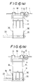
- the hanger H also has opposed rods 22. As shown in Fig. 3, the rods 22 are supported on V-shaped supports 23 projecting upward from the top of each treating tank (as described later), especially those 23 projecting from the top of an electrodeposition coating tank Z g. That is, when the hanger H is lowered into the tank, its rods 22 are supported on the V-shaped supports 23 and thus make it easy to rock the hanger H back and forth in the tank. From the top of the hanger H upwardly projects guide pins 24.
- stoppers 25 are connected to the bottom of the frame 4 of the monorail M.
- Each stopper 25 has an inner cone- shaped space.
- the hanger H carries two baskets B.
- Works W to be coated are loaded into each basket B.
- the four sides and bottom of the basket B may be constructed of wire nets 26 of expanded metal.
- Fig. 4 shows the whole of a system used to carry out the electrodeposition coating method of the invention.
- the system of Fig. 4 may be constructed inside a building.
- the rail is designated by reference numeral 1, it includes the side rails 2 and 3.
- the rail 1 makes a loop.
- the rail 1 may be fixed to the ceiling of the building.
- Plural monorails M from which the hangers H are suspended are hung from the rail system 1.
- the letter Y designates a furnace for heating and drying works W coated in treating tanks Z, to Z 12 .
- the furnace Y has an inlet Y 1 and an cutlet Y 2 .
- Reference numeral 27 designates a supply conveyor.
- In front of the supply conveyor 27 are located three short conveyors 29, 30, and 31.
- In front of the short conveyors are located three parallel basket-receiving rollers 32 connected together.
- the rollers 32 are vertically movable.
- a first loading conveyor 33 is located directly below part of the rail system 1, and overlaps with the rollers 32.
- the first loading conveyor 33 is located at a level slightly lower than the level of the rollers 32 when the rollers 32 have been raised to an upper position. As clearly shown, the first loading conveyor 33 extends perpendicular to the conveyors 27, 29, 30, and 31.
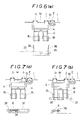
- In front of the first loading conveyor 33 is located a second loading conveyor 35. As best shown in Figs.
- the second loading conveyor 35 is operated by a motor 34 (Fig. 2).
- the second loading conveyor 35 is provided with two front guide plates 36 at its front portion.
- the first loading conveyor 33 is provided with two rear guide plates 36 spaced apart from the front guide plates 36 by a distance substantially equal to the length of the hanger H.
- the guide plates 36 are located not in the centers of the conveyors 33 and 35, but on the sides thereof.
- Fig. 2 shows only one front guide plate 36 and only one rear guide plate 36. The function of the guide plates 36 is to make it easy to position the hanger H properly relative to the conveyors 33 and 35.
- Tanks Z 1 to Z 12 are located directly below a straight portion of the rail 1. In each tank, works W are treated as follows:
- Z 3 , Z 4 , and Z 5 they are showered or immersed in water to wash them.
- Z 1 to Z 7 they are thus conditioned for electrodeposition coating. In each of the tanks Z 1 to Z 7 they are treated for about one minute.
- first and second unloading conveyors 38 and 37 In front of the inlet Y, of the furnace Y is located first and second unloading conveyors 38 and 37. As clearly shown in Figs. 7(a) to 7(e), one end of the first unloading conveyor 38 and one end of the second unloading conveyor 37 are supported by a common spindle. Also as shown in Figs. 7(a) to 7(e), the two unloading conveyors 37 and 38 are vertically movable.
- a conveyor 40 extends through the inlet Y 1 of the furnace Y. Directly in front of the front end of the conveyor 40 is located three basket-receiving rollers 39. As clearly shown in Fig. 7(a), the first unloading conveyor 38 initially overlaps with the rollers 39.
- works W to be electrodeposition coated such as forgings or castings, are loaded into baskets B, and the baskets B are manually placed successively on one end of the supply conveyor 27.
- the baskets B are conveyed by the conveyor 27. After reaching the other end of the conveyor 27, the basket is transferred therefrom onto the conveyor 29, and thence onto the conveyor 30, and thence onto the conveyor 31.
- the vertically-movable rollers 32 are initially in an upper position. From the conveyor 31 the basket is moved onto the rollers 32. Then, the rollers 32 are lowered to place the basket on one end of the first loading conveyor 32.
- a monorail M is above the first and second loading conveyors 33 and 35.
- the hanger H is lowered until the lower end of the hanger H comes into the conveyors 33 and 35 and becomes substantially flush with the lower surfaces of the conveyors 33 and 35.
- the hanger H is lowered exactly to the position of Fig. 6(b) by virtue of the guide plates 36.
- the first loading conveyor 32 is operated to convey the basket toward the hanger H.
- the basket is designated by B i .
- the second loading conveyor 32 is also operated.
- the basket B 1 reaches the second loading conveyor 35.
- the next basket B is conveyed to the front end of the first loading conveyor 33.
- the hanger H is raised.
- the basket supports 20 provided at the lower end of the hanger H come into engagement with the bottoms of the baskets B 1 and B 2 , and support the baskets in this manner while the hanger H is raised.
- the baskets are thus lifted away from the conveyors 33 and 36.
- the basket supports 20 keep supporting the baskets B 1 and B 2 in this manner until the baskets are unloaded from the hanger H.
- four of the eight supports 20 support one basket B 1
- the other four supports 20 support the other basket B 2 .
- Each basket is provided at its bottom with recesses (not shown) which receive the respective basket supports 20. Therefore there is no possibility that the baskets may drop from the hanger H.
- the hanger H is raised until the guide pins 24 engage with the stoppers 25 provided on the bottom of the monorail M. The hanger H is thus joined stably with the monorail M.
- the hanger H is rocked for such angles that the works W are not thrown off the baskets.
- the hanger H When the works W have thus been treated, the hanger H is raised out of the tank Z1. Then, the hanger H is rocked back and forth again as shown in Fig. 5. As a result, the water which has been used to shower the works and may still remain on or in the works is removed, or dropped, into the tank Zi.
- the hanger H is returned completely to the uppermost position. That is, it is raised until the guide pins 24 engage with the stoppers 25. Then, the monorail M moves to the position directly above the second tank Z 2 . Then, the hanger H is lowered into the second tank Z 2 , and the works are alkaline degreased while the hanger H is rocked back and forth. When the works have been treated, the hanger H is raised out of the tank and is rocked back and forth to remove the liquid used to treat the works.
- the monorail M stops and the hanger H is lowered into the tank and is rocked twice before it has been returned to the uppermost position, i.e., first in the tank for the treatment of the entire surface of each work and then above the tank for the removal of the liquid used, except that the hanger H is not rocked, but is returned straight to the uppermost position after it has been rocked in the tanks Z 7 and Z 12 .
- the tanks Z 7 and Z12 contain no liquid, nor is any liquid applied to the works when the works are in the two tanks. When the works are in the two tanks, the liquids used in the preceding tanks are only removed therefrom by rocking the hanger.
- the first and second unloading conveyors 38 and 37 are initially in a lower position, as shown in Fig. 7(a). Following treatment in the last tank Z 12 , the works are conveyed to the position in front of the furnace Y. That is, following treatment of the works in the last tank Z 12 , the monorail M comes to the position directly above the unloading conveyors 38 and 37, as shown in Fig. 7(a). When the monorail M has reached that position, it stops. Then, as shown in Fig. 7(b), the unloading conveyors 38 and 37 are raised to lift the baskets B 2 and B i , respectively, away from the basket supports 20 of the hanger H. Thereupon, as shown in Fig. 7(c), the monorail M restarts.
- the conveyors 38 and 37 are lowered.
- the basket B 2 is placed on the rollers 39.
- the rollers 39 are rotated to transfer the basket B 2 onto the conveyor 40, and then the basket B 2 is moved into the furnace Y by the conveyor 40.
- the conveyors 38 and 37 are raised a little, and the conveyor 37 is rotated to move the basket B 1 onto the conveyor 38.
- the conveyors 38 and 37 are lowered to place the basket B 1 on the rollers 39.
- the rollers 39 are rotated to transfer the basket B 1 onto the conveyor 40.
- the upper space in the furnace Y is divided from the lower space therein by a floor member (not shown). Also, a conveyor (not shown) is provided in the upper space, and extends from end to end of the upper space.
- a front elevator (not shown) is provided near the inlet Yi, and a rear elevator (not shown) is provided near the outlet Y 2 .
- the basket Immediately after entering the furnace Y, the basket is lifted to its upper space by the front elevator, and is conveyed therethrough. As it is conveyed therethrough, the works W in it are heated and dried.
- the basket When the basket has reached the rear end of the upper space, the basket is lowered by the rear elevator and is moved outside the furnace Y from its outlet Y 2 . Then, the basket is transferred onto a conveyor located between the furnace Y and the supply conveyor 27.
- the monorail M is moved by the locomotive E. If desired, however, the locomotive E may be omitted and instead the suspension J 1 or and J 2 may be provided with a mechanism for moving the monorail M.
- a vehicle suspended from conveyor chains may be used instead of the monorail M. That is, conveyor chains may be provided along the rail 1, and a vehicle from which the hanger H is hung may be suspended from the conveyor chains. In this case, the vehicle is moved with the conveyor chains by operating the conveyor chains.
- the hanger H may be entirely omitted and instead the baskets may be hung directly from the chains F 1 , F 2 , R i , and R 2 .
Landscapes
- Chemical & Material Sciences (AREA)
- Engineering & Computer Science (AREA)
- Chemical Kinetics & Catalysis (AREA)
- Electrochemistry (AREA)
- Materials Engineering (AREA)
- Metallurgy (AREA)
- Organic Chemistry (AREA)
- Coating Apparatus (AREA)
Applications Claiming Priority (2)
| Application Number | Priority Date | Filing Date | Title |
|---|---|---|---|
| JP155193/91 | 1991-05-30 | ||
| JP3155193A JP2607982B2 (ja) | 1991-05-30 | 1991-05-30 | 電着塗装装置 |
Publications (2)
| Publication Number | Publication Date |
|---|---|
| EP0525326A1 true EP0525326A1 (de) | 1993-02-03 |
| EP0525326B1 EP0525326B1 (de) | 1996-04-10 |
Family
ID=15600527
Family Applications (1)
| Application Number | Title | Priority Date | Filing Date |
|---|---|---|---|
| EP92108977A Expired - Lifetime EP0525326B1 (de) | 1991-05-30 | 1992-05-27 | Verfahren zur Elektrobeschichtung von Artikeln mit Farbe |
Country Status (7)
| Country | Link |
|---|---|
| US (1) | US5228961A (de) |
| EP (1) | EP0525326B1 (de) |
| JP (1) | JP2607982B2 (de) |
| CA (1) | CA2069587A1 (de) |
| DE (1) | DE4217615A1 (de) |
| GB (1) | GB2264506B (de) |
| TW (1) | TW199187B (de) |
Families Citing this family (14)
| Publication number | Priority date | Publication date | Assignee | Title |
|---|---|---|---|---|
| DE4214448A1 (de) * | 1992-05-06 | 1993-11-11 | Roka Werk Gmbh Daemmbau Elemen | Verfahren und Vorrichtung zum schwimmenden Ausbacken von Teiglingen |
| DE19706175A1 (de) * | 1997-02-17 | 1998-08-27 | Eisenmann Kg Maschbau | Durchlaufanlage für die Behandlung von Werkstücken |
| JP3148178B2 (ja) * | 1998-05-14 | 2001-03-19 | 日鉱金属株式会社 | 頭上移動形クレーンシステム |
| GB0016960D0 (en) | 2000-07-12 | 2000-08-30 | Bae Systems Plc | A jig and a method and appratus of applying a surface treatment to a member on the jig |
| DE10161086B4 (de) * | 2001-12-12 | 2005-06-02 | Wmv Apparatebau Gmbh & Co Kg | Anlage zum Behandeln von Massenteilen |
| DE10345102B4 (de) * | 2003-09-26 | 2005-09-29 | Demag Cranes & Components Gmbh | Laufkatze, insbesondere Einschienenkatze mit niedriger Bauhöhe |
| JP2006199948A (ja) * | 2004-12-21 | 2006-08-03 | Nippon Paint Co Ltd | ネジ塗装用カチオン電着塗料組成物 |
| BRPI0821810B1 (pt) * | 2007-12-28 | 2018-10-09 | Eisenmann Ag | instalação de tratamento por imersão |
| DE102009017151A1 (de) * | 2009-04-15 | 2010-10-21 | Eisenmann Anlagenbau Gmbh & Co. Kg | Anlage zur Tauchbehandlung |
| JP6221558B2 (ja) * | 2013-09-24 | 2017-11-01 | トヨタ車体株式会社 | 搬送装置 |
| DE102015105786B4 (de) * | 2015-04-15 | 2018-12-06 | Wilhelm Ungeheuer Söhne GmbH | Verfahren und Vorrichtung zur Handhabung von Vorbehandlungsbehältnissen zur Vorbehandlung von zu beschichtenden Gegenständen |
| CN106319602A (zh) * | 2016-09-18 | 2017-01-11 | 江苏友邦精工实业有限公司 | 电泳装置 |
| GB2576290A (en) * | 2018-04-30 | 2020-02-19 | Rolls Royce Plc | A carrier for holding a plurality of articles |
| CN109537027B (zh) * | 2018-12-29 | 2023-11-24 | 无锡艾赛特科技有限公司 | 一种电泳装置及电泳生产线 |
Citations (3)
| Publication number | Priority date | Publication date | Assignee | Title |
|---|---|---|---|---|
| DE2904176A1 (de) * | 1979-02-05 | 1980-08-07 | B & W Transportsysteme Gmbh | Verfahren und vorrichtung zum konservieren von werkstuecken durch beschichten im tauchverfahren |
| EP0146437A1 (de) * | 1983-11-14 | 1985-06-26 | Thomas Norman Urquhart | Verfahren und Vorrichtung zur elektrophoretischen Beschichtung |
| US4812211A (en) * | 1987-10-31 | 1989-03-14 | Hideyuki Sakai | Process and system for electrodeposition coating |
Family Cites Families (5)
| Publication number | Priority date | Publication date | Assignee | Title |
|---|---|---|---|---|
| US4337135A (en) * | 1978-10-06 | 1982-06-29 | Bunker Ramo Corporation | Barrel plating apparatus |
| JPH0815582B2 (ja) * | 1987-02-28 | 1996-02-21 | 本田技研工業株式会社 | 車体の表面処理方法 |
| US4740285A (en) * | 1987-09-11 | 1988-04-26 | Usui Kokusai Sangyo Kabushiki Kaisha | Plating hooking apparatus |
| JP2648930B2 (ja) * | 1988-05-23 | 1997-09-03 | 臼井国際産業株式会社 | 電気メッキ用引掛け装置 |
| JPH032397A (ja) * | 1989-05-29 | 1991-01-08 | Suzuki Motor Corp | 電着塗装装置 |
-
1991
- 1991-05-30 JP JP3155193A patent/JP2607982B2/ja not_active Expired - Lifetime
-
1992
- 1992-05-20 US US07/885,969 patent/US5228961A/en not_active Expired - Fee Related
- 1992-05-22 GB GB9210917A patent/GB2264506B/en not_active Expired - Fee Related
- 1992-05-22 TW TW081104018A patent/TW199187B/zh active
- 1992-05-26 CA CA002069587A patent/CA2069587A1/en not_active Abandoned
- 1992-05-27 EP EP92108977A patent/EP0525326B1/de not_active Expired - Lifetime
- 1992-05-27 DE DE4217615A patent/DE4217615A1/de not_active Withdrawn
Patent Citations (3)
| Publication number | Priority date | Publication date | Assignee | Title |
|---|---|---|---|---|
| DE2904176A1 (de) * | 1979-02-05 | 1980-08-07 | B & W Transportsysteme Gmbh | Verfahren und vorrichtung zum konservieren von werkstuecken durch beschichten im tauchverfahren |
| EP0146437A1 (de) * | 1983-11-14 | 1985-06-26 | Thomas Norman Urquhart | Verfahren und Vorrichtung zur elektrophoretischen Beschichtung |
| US4812211A (en) * | 1987-10-31 | 1989-03-14 | Hideyuki Sakai | Process and system for electrodeposition coating |
Also Published As
| Publication number | Publication date |
|---|---|
| US5228961A (en) | 1993-07-20 |
| GB2264506A (en) | 1993-09-01 |
| JP2607982B2 (ja) | 1997-05-07 |
| EP0525326B1 (de) | 1996-04-10 |
| GB9210917D0 (en) | 1992-07-08 |
| DE4217615A1 (de) | 1993-01-07 |
| TW199187B (de) | 1993-02-01 |
| CA2069587A1 (en) | 1992-12-01 |
| JPH0726396A (ja) | 1995-01-27 |
| GB2264506B (en) | 1995-08-23 |
Similar Documents
| Publication | Publication Date | Title |
|---|---|---|
| US5228961A (en) | Process for electrodeposition coating works with paint | |
| RU2192316C2 (ru) | Способ подачи и удаления деталей, в частности автомобильных кузовов, а также устройство и установка для поверхностной обработки деталей | |
| US6372107B1 (en) | Process and conveyor device for conveying vehicle bodies through a treatment tank | |
| KR970008587B1 (ko) | 컨베이어용 행거 | |
| JPH0465917B2 (de) | ||
| JPH108292A (ja) | 表面処理装置及び表面処理方法 | |
| JP3477475B2 (ja) | 表面処理用被処理物搬送方法及びその装置 | |
| KR950012430B1 (ko) | 전착 도장방법 | |
| JP3615877B2 (ja) | 塗装設備 | |
| JP3615876B2 (ja) | 塗装設備 | |
| US6224314B1 (en) | Universal rack loading/unloading system | |
| JPS63134420A (ja) | 被処理物容器の搬送装置 | |
| JPS6131695B2 (de) | ||
| JPH024488B2 (de) | ||
| JPH03215698A (ja) | 自動車用電着塗装装置 | |
| RU2771830C1 (ru) | Установка для погружения кузовов автомобилей | |
| JPH02243798A (ja) | 電気機器ケースの電着塗装装置 | |
| JPH11111437A (ja) | 高周波誘導加熱式食品加熱装置 | |
| SU986971A1 (ru) | Саморазгружающеес устройство дл гальванических линий | |
| JP2649639B2 (ja) | 電着塗装物の移載搬送装置 | |
| JPH03223494A (ja) | 自動車用電着塗装装置 | |
| JPH0629142Y2 (ja) | 昇降装置付き液処理設備 | |
| JPS6316473B2 (de) | ||
| JPH06228793A (ja) | 電着塗装用搬送装置 | |
| SU1073343A1 (ru) | Автооператорна лини дл жидкостной обработки изделий |
Legal Events
| Date | Code | Title | Description |
|---|---|---|---|
| PUAI | Public reference made under article 153(3) epc to a published international application that has entered the european phase |
Free format text: ORIGINAL CODE: 0009012 |
|
| AK | Designated contracting states |
Kind code of ref document: A1 Designated state(s): BE FR IT NL SE |
|
| RIN1 | Information on inventor provided before grant (corrected) |
Inventor name: SAKAI, HIDEYUKI |
|
| 17P | Request for examination filed |
Effective date: 19930723 |
|
| 17Q | First examination report despatched |
Effective date: 19940909 |
|
| GRAH | Despatch of communication of intention to grant a patent |
Free format text: ORIGINAL CODE: EPIDOS IGRA |
|
| GRAA | (expected) grant |
Free format text: ORIGINAL CODE: 0009210 |
|
| AK | Designated contracting states |
Kind code of ref document: B1 Designated state(s): BE FR IT NL SE |
|
| ITF | It: translation for a ep patent filed |
Owner name: BUGNION S.P.A. |
|
| ET | Fr: translation filed | ||
| PLBE | No opposition filed within time limit |
Free format text: ORIGINAL CODE: 0009261 |
|
| STAA | Information on the status of an ep patent application or granted ep patent |
Free format text: STATUS: NO OPPOSITION FILED WITHIN TIME LIMIT |
|
| 26N | No opposition filed | ||
| PGFP | Annual fee paid to national office [announced via postgrant information from national office to epo] |
Ref country code: SE Payment date: 19980518 Year of fee payment: 7 |
|
| PGFP | Annual fee paid to national office [announced via postgrant information from national office to epo] |
Ref country code: NL Payment date: 19980527 Year of fee payment: 7 Ref country code: FR Payment date: 19980527 Year of fee payment: 7 |
|
| PGFP | Annual fee paid to national office [announced via postgrant information from national office to epo] |
Ref country code: BE Payment date: 19980604 Year of fee payment: 7 |
|
| PG25 | Lapsed in a contracting state [announced via postgrant information from national office to epo] |
Ref country code: SE Free format text: LAPSE BECAUSE OF NON-PAYMENT OF DUE FEES Effective date: 19990528 |
|
| PG25 | Lapsed in a contracting state [announced via postgrant information from national office to epo] |
Ref country code: BE Free format text: LAPSE BECAUSE OF NON-PAYMENT OF DUE FEES Effective date: 19990531 |
|
| BERE | Be: lapsed |
Owner name: NICHIDAI INDUSTRIAL CO. LTD Effective date: 19990531 |
|
| PG25 | Lapsed in a contracting state [announced via postgrant information from national office to epo] |
Ref country code: NL Free format text: LAPSE BECAUSE OF NON-PAYMENT OF DUE FEES Effective date: 19991201 |
|
| EUG | Se: european patent has lapsed |
Ref document number: 92108977.7 |
|
| PG25 | Lapsed in a contracting state [announced via postgrant information from national office to epo] |
Ref country code: FR Free format text: LAPSE BECAUSE OF NON-PAYMENT OF DUE FEES Effective date: 20000131 |
|
| NLV4 | Nl: lapsed or anulled due to non-payment of the annual fee |
Effective date: 19991201 |
|
| REG | Reference to a national code |
Ref country code: FR Ref legal event code: ST |
|
| PG25 | Lapsed in a contracting state [announced via postgrant information from national office to epo] |
Ref country code: IT Free format text: LAPSE BECAUSE OF NON-PAYMENT OF DUE FEES;WARNING: LAPSES OF ITALIAN PATENTS WITH EFFECTIVE DATE BEFORE 2007 MAY HAVE OCCURRED AT ANY TIME BEFORE 2007. THE CORRECT EFFECTIVE DATE MAY BE DIFFERENT FROM THE ONE RECORDED. Effective date: 20050527 |