EP0504458A1 - Passage d'intercommunication entre deux véhicules, notamment des véhicules ferroviaires - Google Patents
Passage d'intercommunication entre deux véhicules, notamment des véhicules ferroviaires Download PDFInfo
- Publication number
- EP0504458A1 EP0504458A1 EP91104389A EP91104389A EP0504458A1 EP 0504458 A1 EP0504458 A1 EP 0504458A1 EP 91104389 A EP91104389 A EP 91104389A EP 91104389 A EP91104389 A EP 91104389A EP 0504458 A1 EP0504458 A1 EP 0504458A1
- Authority
- EP
- European Patent Office
- Prior art keywords
- transition
- transition according
- carriage
- piston
- bellows
- Prior art date
- Legal status (The legal status is an assumption and is not a legal conclusion. Google has not performed a legal analysis and makes no representation as to the accuracy of the status listed.)
- Granted
Links
Images


Classifications
-
- B—PERFORMING OPERATIONS; TRANSPORTING
- B61—RAILWAYS
- B61D—BODY DETAILS OR KINDS OF RAILWAY VEHICLES
- B61D17/00—Construction details of vehicle bodies
- B61D17/04—Construction details of vehicle bodies with bodies of metal; with composite, e.g. metal and wood body structures
- B61D17/20—Communication passages between coaches; Adaptation of coach ends therefor
Definitions
- the invention relates to a transition between two vehicles, in particular between two rail vehicles, with a transition bridge and with a bellows which is connected to the vehicle at one end and which has a coupling frame at its other end.
- the transition represents the connection between two vehicles. It can be formed in one part or in two parts, the transition being composed of two transition halves in the case of a two-part construction. In this latter case, the dome frames represent the links between the two halves. In the following, the term transition therefore includes both the two-part and the one-part embodiment. Transitions of the type mentioned are known. Such transitions are often used as a connection between so-called railcars; Railcars are rail vehicles in which each car is able to act independently as a towing vehicle.
- the invention is therefore based on the object of developing a transition of the type mentioned in such a way that when the railcars of a railcar train are uncoupled, the transitions are automatically retracted into their starting position.
- the transition is displaceable by means of a piston-cylinder drive arranged on the vehicle;
- the transition from the uncoupling process to the end position on the vehicle is used by the piston-cylinder drive.
- the transition according to the invention is characterized in that the piston-cylinder drive is connected to a travel device which is connected to the transition.
- the piston-cylinder drive thus does not act directly on the transition, but rather indirectly through the travel device.
- the transition bridge which is preferably in the manner of a parallel link, e.g. is designed as a link bridge, in order to be able to compensate for lateral movements during cornering of the train, is connected on the coupling frame side, in particular by articulation to the coupling frame, with the bellows and on the vehicle side with the travel device. It follows from this that when the travel device moves, the bellows performs a corresponding movement.
- the traversing device consists of two traversing elements, one traversing element being designed as a slide which can be coupled to the second traversing element designed as a roller carriage.
- the carriage is only coupled to the roller carriage if the transition or the bellows is to be used on the vehicle.
- at least one coupling device is provided for this purpose, which has a pivotable hook which engages in corresponding recesses in the opposite part; the hook can also be actuated by means of a piston-cylinder drive.
- the slide which is connected to the transition bridge, and the roller carriage are mounted so as to be movable relative to one another, for which purpose it is advantageous the slide is slidably arranged on the side members of the roller carriage. Due to this design, driving movements can be given, so that a transfer of these movements to the piston-cylinder drive is excluded.
- the carriage has lateral guide rollers which bear against the inner surfaces of the side members.
- the carriage In order to prevent the carriage from being lifted off the roller carriage, the carriage has shoes on its underside which engage under the respective longitudinal member.
- the slide In order to be able to give in to rotational movements in the vertical direction, the slide is connected to the transition bridge by means of a hinge.
- the traversing device consisting of a carriage and roller carriage, has an elastic element for stabilization in the axial direction, for example a spring in the form of a leaf spring, through which the carriage is connected to the roller carriage.
- This leaf spring is able to absorb compressive forces due to its arrangement between the carriage and roller carriage.
- the transmission of tensile forces, such as occur when the transition is pulled together, is done by coupling the roller carriage to the carriage.
- the roller carriage is guided in a box-shaped frame, in which the piston-cylinder drive for the roller carriage is arranged, the roller carriage being both rollers and laterally arranged rollers for guidance in the frame. This largely prevents the roller carriage from tilting in the box-shaped frame.
- the bellows is advantageously fixed to the front of the vehicle by means of a locking device consisting of a locking bar and locking latch.
- an actuating device for example a piston-cylinder drive, which pivots the bolt against a force, for example gravity, out of the bolt latch.
- the bolt is held in the bolt latch by gravity;
- the bolt is held in the bolt latch by a spring, the bolt then being pivoted out of the bolt latch against the spring force by the piston-cylinder drive. In the latter case in particular, unintentional unlocking is impossible.
- the bolt or the bolt latch is designed so that the bolt automatically runs into the bolt latch.
- a tension element is arranged in the area of the roof of the bellows, which is connected at the end to the vehicle.
- the tension element advantageously consists of a piston-cylinder drive arranged on the roof of the vehicle, which is connected at the end to the bellows by a flexible force transmission element, for example by a rope.
- the tension element is therefore only activated when the bellows is to be contracted.
- the device arranged on the roof of the bellows is not necessary, since the bellows in the retracted state has the tendency to push apart due to its own bias.
- the transition designated overall by 1 has a bellows 2, which has at one end a coupling frame 3 for connection to the opposite transition, and which is connected at its other end to the vehicle frame 4.
- the transition bridge 5 which is designed as a link bridge and is connected on the one hand to the coupling frame 3 and on the other hand to the movement device designated overall by 6; the travel device 6 is mounted in the box-shaped frame 22 of the vehicle 1a.
- the dome frame 3 can be fixed to the vehicle frame 4 by the locking device 7.
- the piston-cylinder drive 8 is located on the roof of the vehicle 1a, the piston 8a being connected to the coupling frame 3 by means of a cable 9.
- the traversing device designated overall by 6, can be seen in a plan view in FIG. 2.
- the movement device consists in detail of the roller carriage 10 and the slide 11.
- the slide 11 is connected here by hinges 12 to the link bridge 5 (FIG. 3) in order to be able to yield movements of the link bridge 5 in the vertical direction.
- the link bridge 5 is articulated by the pivot bearing 13 on the coupling frame 3 so as to rotate in horizontal direction, as occurs, for example, when the railcar train is cornering. Since the transition bridge 5 is designed as a link bridge and is therefore also flexible in the horizontal direction, this constructive design prevents the occurrence of tension in the transition 1
- the roller carriage 10 consists in particular of two parallel longitudinal beams 10a, which are connected by the cross members 10b and 10c.
- the carriage 11 is slidably mounted on the longitudinal beams 10a.
- a sliding layer 10d can be applied to the longitudinal beams 10a.
- the slide has guide rollers 20 arranged laterally in the region of the inner surfaces of the longitudinal members 10a;
- the carriage has a shoe 20a on both sides which engages under the respective longitudinal member 10a (FIG. 4).
- roller carriage 10 is connected to the carriage 11 by the leaf spring 19.
- the ends of the leaf spring 19 each abut against the bearing crossbeam 11a of the slide 11 and is clamped approximately centrally at 21 by the crossbeam 10b of the roller carriage 10.
- the roller carriage 10 can be coupled to the carriage 11 by two coupling devices 14.
- the coupling device 14 consists of a piston-cylinder drive 15, by means of which a lever 16 arranged on the roller carriage 10 can be pivoted about an axis 17 into a recess 18 arranged in the carriage 11 (FIG. 5).
- the entire traversing device 6, consisting of roller carriages 10 and slides 11, is movably supported in the box-shaped frame 22 arranged on the vehicle.
- the roller carriage is provided with casters 23 and laterally arranged guide rollers 24, which have the task of preventing the roller carriage from tilting in the box-shaped frame 22 during the movement.
- the piston-cylinder drive 25 is arranged approximately in the center of the roller carriage 10 in the box-shaped frame 22 in the longitudinal axis.
- the cylinder of the piston-cylinder drive 25 is fastened in the box-shaped frame 22 to the bearing block 26.
- the piston 25a of the piston-cylinder drive 25 is articulated on the cross member 10a of the roller carriage 10.
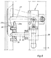
- the overall locking device designated 7 (FIG. 6) consists of the pivotable locking bar 27 arranged on the frame 4 of the vehicle 1a, which engages in a locking latch 28 located on the coupling frame 3.
- the locking head 27a is slightly curved inwards;
- the bolt holder 28a of the bolt latch 28 is slightly beveled on the outside in order to allow the bolt 27 to enter the bolt latch 28.
- a piston-cylinder drive 29 is provided on the frame 4, by means of which the bolt 27 is pivoted upward out of the bolt latch 28 against gravity.
- the centering device 30 consisting of a centering mandrel 31, which runs into a correspondingly designed bore 33 in the coupling frame 3.
- the device works as follows:
- the carriage 11 is first coupled to the roller carriage 10 by means of the two coupling devices 14 and then the roller carriage is moved into the dashed position shown in FIG. 2 by the piston-cylinder drive.
- the carriage 11 is connected by the link bridge 5 to the coupling frame 3 by the pivot bearing 13.
- Parallel to the movement of the piston 25a of the piston-cylinder drive 25, the piston 8a of the piston-cylinder drive 8 is drawn into its cylinder, the coupling frame 3 and thus the bellows 2 also being tightened by the cable 9 which is fastened to the coupling frame 3 the frame 4 can be used.
Landscapes
- Engineering & Computer Science (AREA)
- Life Sciences & Earth Sciences (AREA)
- Wood Science & Technology (AREA)
- Mechanical Engineering (AREA)
- Actuator (AREA)
- Automobile Manufacture Line, Endless Track Vehicle, Trailer (AREA)
Priority Applications (3)
| Application Number | Priority Date | Filing Date | Title |
|---|---|---|---|
| DE59101451T DE59101451D1 (de) | 1991-03-21 | 1991-03-21 | Übergang zwischen zwei Fahrzeugen, insbesondere zwischen zwei Schienenfahrzeugen. |
| ES91104389T ES2051535T3 (es) | 1991-03-21 | 1991-03-21 | Corredor de enlace entre dos vehiculos, particularmente dos vehiculos sobre carriles. |
| EP19910104389 EP0504458B1 (fr) | 1991-03-21 | 1991-03-21 | Passage d'intercommunication entre deux véhicules, notamment des véhicules ferroviaires |
Applications Claiming Priority (1)
| Application Number | Priority Date | Filing Date | Title |
|---|---|---|---|
| EP19910104389 EP0504458B1 (fr) | 1991-03-21 | 1991-03-21 | Passage d'intercommunication entre deux véhicules, notamment des véhicules ferroviaires |
Publications (2)
| Publication Number | Publication Date |
|---|---|
| EP0504458A1 true EP0504458A1 (fr) | 1992-09-23 |
| EP0504458B1 EP0504458B1 (fr) | 1994-04-20 |
Family
ID=8206551
Family Applications (1)
| Application Number | Title | Priority Date | Filing Date |
|---|---|---|---|
| EP19910104389 Expired - Lifetime EP0504458B1 (fr) | 1991-03-21 | 1991-03-21 | Passage d'intercommunication entre deux véhicules, notamment des véhicules ferroviaires |
Country Status (3)
| Country | Link |
|---|---|
| EP (1) | EP0504458B1 (fr) |
| DE (1) | DE59101451D1 (fr) |
| ES (1) | ES2051535T3 (fr) |
Cited By (4)
| Publication number | Priority date | Publication date | Assignee | Title |
|---|---|---|---|---|
| EP0958981A1 (fr) * | 1998-05-16 | 1999-11-24 | HÜBNER Gummi- und Kunststoff GmbH | Passage entre deux véhicules ou parties de véhicule reliés de manière articulée notamment entre deux autorails reliés de manière articulée |
| EP2236382A1 (fr) | 2009-04-02 | 2010-10-06 | Hübner GmbH | Dispositif d'intercirculation avec soufflet déformable, pour vehicles ferroviaires |
| EP2399798A1 (fr) * | 2010-06-25 | 2011-12-28 | Hübner GmbH | Intercirculation entre deux véhicules reliés par une articulation, notamment des véhicules ferroviaires, comprenant une paserelle et un soufflet |
| WO2020221102A1 (fr) * | 2019-04-30 | 2020-11-05 | 比亚迪股份有限公司 | Mécanisme d'accouplement et de désolidarisation, passage et train |
Citations (3)
| Publication number | Priority date | Publication date | Assignee | Title |
|---|---|---|---|---|
| DE2526703A1 (de) * | 1975-06-14 | 1976-12-30 | Scharfenbergkupplung Gmbh | Uebergangsschutz zwischen zwei miteinander kuppelbaren fahrzeugen |
| DE2636082A1 (de) * | 1976-08-11 | 1978-02-16 | Scharfenbergkupplung Gmbh | Uebergangsschutz fuer fahrzeuge |
| EP0331121A2 (fr) * | 1988-03-02 | 1989-09-06 | HÜBNER Gummi- und Kunststoff GmbH | Elément de passerelle d'intercommunication séparable pour véhicules |
-
1991
- 1991-03-21 DE DE59101451T patent/DE59101451D1/de not_active Expired - Fee Related
- 1991-03-21 ES ES91104389T patent/ES2051535T3/es not_active Expired - Lifetime
- 1991-03-21 EP EP19910104389 patent/EP0504458B1/fr not_active Expired - Lifetime
Patent Citations (3)
| Publication number | Priority date | Publication date | Assignee | Title |
|---|---|---|---|---|
| DE2526703A1 (de) * | 1975-06-14 | 1976-12-30 | Scharfenbergkupplung Gmbh | Uebergangsschutz zwischen zwei miteinander kuppelbaren fahrzeugen |
| DE2636082A1 (de) * | 1976-08-11 | 1978-02-16 | Scharfenbergkupplung Gmbh | Uebergangsschutz fuer fahrzeuge |
| EP0331121A2 (fr) * | 1988-03-02 | 1989-09-06 | HÜBNER Gummi- und Kunststoff GmbH | Elément de passerelle d'intercommunication séparable pour véhicules |
Cited By (5)
| Publication number | Priority date | Publication date | Assignee | Title |
|---|---|---|---|---|
| EP0958981A1 (fr) * | 1998-05-16 | 1999-11-24 | HÜBNER Gummi- und Kunststoff GmbH | Passage entre deux véhicules ou parties de véhicule reliés de manière articulée notamment entre deux autorails reliés de manière articulée |
| EP2236382A1 (fr) | 2009-04-02 | 2010-10-06 | Hübner GmbH | Dispositif d'intercirculation avec soufflet déformable, pour vehicles ferroviaires |
| EP2399798A1 (fr) * | 2010-06-25 | 2011-12-28 | Hübner GmbH | Intercirculation entre deux véhicules reliés par une articulation, notamment des véhicules ferroviaires, comprenant une paserelle et un soufflet |
| CN102328668A (zh) * | 2010-06-25 | 2012-01-25 | 许布奈有限公司 | 两个通过铰接件彼此连接的车辆如有轨车辆之间的过渡部 |
| WO2020221102A1 (fr) * | 2019-04-30 | 2020-11-05 | 比亚迪股份有限公司 | Mécanisme d'accouplement et de désolidarisation, passage et train |
Also Published As
| Publication number | Publication date |
|---|---|
| EP0504458B1 (fr) | 1994-04-20 |
| ES2051535T3 (es) | 1994-06-16 |
| DE59101451D1 (de) | 1994-05-26 |
Similar Documents
| Publication | Publication Date | Title |
|---|---|---|
| DE2757201C2 (de) | Übergangseinrichtung zwischen Fahrzeugen, insbesondere Eisenbahnfahrzeugen | |
| DE19513386A1 (de) | Längenverstellbare Kupplungsstange | |
| DE2420742B2 (de) | Weiche fuer hohe fahrgeschwindigkeit | |
| EP0504458B1 (fr) | Passage d'intercommunication entre deux véhicules, notamment des véhicules ferroviaires | |
| DE2164042C3 (de) | Schienengebundene Bahn | |
| EP0854813B1 (fr) | Passage entre deux vehicules relies de maniere articulee, par ex. des voitures voyageurs ou des wagons de metro | |
| DE490825C (de) | Wagen fuer Eisenbahnen, Strassenbahnen, Schnellbahnen u. dgl., insbesondere fuer Gelenkwagenzuege | |
| DE1455289C3 (de) | Kupplungsvorrichtung zum Verbinden eines für schienengebundenen Betrieb einrichtbaren, zum Rangieren dienenden Antriebsfahrzeugs mit einem Eisenbahnwagen | |
| DE2325074A1 (de) | Schnabelwagen | |
| DE1680207B2 (de) | Kraftfahrzeug mit einer vorrichtung zum transportieren und verlegen einer mit auffahrrampen versehenen klappbruecke | |
| EP2236382B1 (fr) | Dispositif d'intercirculation avec soufflet déformable, pour vehicles ferroviaires | |
| WO2000024627A1 (fr) | Procede et dispositif pour le positionnement d'un train | |
| EP0330742B1 (fr) | Dispositif d'intercirculation pour véhicules ferroviaires | |
| EP0808759A1 (fr) | Arrangement d'attelage pour véhicules ferroviaires notamment locomotives à triage | |
| EP3922488B1 (fr) | Transition entre deux pièces de véhicule raccordées au moyen d'une articulation ou d'un couplage | |
| EP0709271B1 (fr) | Chariot de triage | |
| EP0493818B1 (fr) | Passerelle d'intercommunication pour des véhicules ferroviaires | |
| DE3914506C1 (en) | Monorail train for underground mining - is driven solely by cable-hauled trolley in steep sectors so force flux between train drive and rail is interrupted by coupling rod | |
| AT413684B (de) | Zugwechsel mittels frontübergang | |
| DE3807666C1 (en) | Tramway transport device | |
| DE19515109A1 (de) | Ladungsträger, insbesondere Wechselaufbau oder Container von Lastfahrzeugen | |
| DE102009012081B3 (de) | Mitnehmer für eine Waggonverschiebeeinrichtung | |
| AT349057B (de) | Radsatzwagen einer waggonrangieranlage | |
| DE102015214747A1 (de) | Übergangseinrichtung für Schienenfahrzeuge | |
| DE19520549A1 (de) | Straßen-Schienen-Transportsystem |
Legal Events
| Date | Code | Title | Description |
|---|---|---|---|
| PUAI | Public reference made under article 153(3) epc to a published international application that has entered the european phase |
Free format text: ORIGINAL CODE: 0009012 |
|
| 17P | Request for examination filed |
Effective date: 19911227 |
|
| AK | Designated contracting states |
Kind code of ref document: A1 Designated state(s): AT BE CH DE DK ES FR GB GR IT LI NL SE |
|
| 17Q | First examination report despatched |
Effective date: 19930318 |
|
| RBV | Designated contracting states (corrected) |
Designated state(s): DE ES FR GB IT |
|
| GRAA | (expected) grant |
Free format text: ORIGINAL CODE: 0009210 |
|
| AK | Designated contracting states |
Kind code of ref document: B1 Designated state(s): DE ES FR GB IT |
|
| REF | Corresponds to: |
Ref document number: 59101451 Country of ref document: DE Date of ref document: 19940526 |
|
| REG | Reference to a national code |
Ref country code: ES Ref legal event code: FG2A Ref document number: 2051535 Country of ref document: ES Kind code of ref document: T3 |
|
| ITF | It: translation for a ep patent filed |
Owner name: STUDIO JAUMANN |
|
| GBT | Gb: translation of ep patent filed (gb section 77(6)(a)/1977) |
Effective date: 19940627 |
|
| ET | Fr: translation filed | ||
| PLBE | No opposition filed within time limit |
Free format text: ORIGINAL CODE: 0009261 |
|
| STAA | Information on the status of an ep patent application or granted ep patent |
Free format text: STATUS: NO OPPOSITION FILED WITHIN TIME LIMIT |
|
| 26N | No opposition filed | ||
| PGFP | Annual fee paid to national office [announced via postgrant information from national office to epo] |
Ref country code: FR Payment date: 20010313 Year of fee payment: 11 |
|
| PGFP | Annual fee paid to national office [announced via postgrant information from national office to epo] |
Ref country code: ES Payment date: 20010316 Year of fee payment: 11 |
|
| REG | Reference to a national code |
Ref country code: GB Ref legal event code: IF02 |
|
| PG25 | Lapsed in a contracting state [announced via postgrant information from national office to epo] |
Ref country code: ES Free format text: LAPSE BECAUSE OF NON-PAYMENT OF DUE FEES Effective date: 20020322 |
|
| PG25 | Lapsed in a contracting state [announced via postgrant information from national office to epo] |
Ref country code: FR Free format text: LAPSE BECAUSE OF NON-PAYMENT OF DUE FEES Effective date: 20021129 |
|
| REG | Reference to a national code |
Ref country code: FR Ref legal event code: ST |
|
| REG | Reference to a national code |
Ref country code: ES Ref legal event code: FD2A Effective date: 20030410 |
|
| PG25 | Lapsed in a contracting state [announced via postgrant information from national office to epo] |
Ref country code: IT Free format text: LAPSE BECAUSE OF NON-PAYMENT OF DUE FEES;WARNING: LAPSES OF ITALIAN PATENTS WITH EFFECTIVE DATE BEFORE 2007 MAY HAVE OCCURRED AT ANY TIME BEFORE 2007. THE CORRECT EFFECTIVE DATE MAY BE DIFFERENT FROM THE ONE RECORDED. Effective date: 20050321 |
|
| PGFP | Annual fee paid to national office [announced via postgrant information from national office to epo] |
Ref country code: GB Payment date: 20080320 Year of fee payment: 18 |
|
| PGFP | Annual fee paid to national office [announced via postgrant information from national office to epo] |
Ref country code: DE Payment date: 20080223 Year of fee payment: 18 |
|
| GBPC | Gb: european patent ceased through non-payment of renewal fee |
Effective date: 20090321 |
|
| PG25 | Lapsed in a contracting state [announced via postgrant information from national office to epo] |
Ref country code: DE Free format text: LAPSE BECAUSE OF NON-PAYMENT OF DUE FEES Effective date: 20091001 |
|
| PG25 | Lapsed in a contracting state [announced via postgrant information from national office to epo] |
Ref country code: GB Free format text: LAPSE BECAUSE OF NON-PAYMENT OF DUE FEES Effective date: 20090321 |