EP0501276A2 - Revêtement de l'enveloppe moteur d'un véhicule automobile - Google Patents
Revêtement de l'enveloppe moteur d'un véhicule automobile Download PDFInfo
- Publication number
- EP0501276A2 EP0501276A2 EP92102642A EP92102642A EP0501276A2 EP 0501276 A2 EP0501276 A2 EP 0501276A2 EP 92102642 A EP92102642 A EP 92102642A EP 92102642 A EP92102642 A EP 92102642A EP 0501276 A2 EP0501276 A2 EP 0501276A2
- Authority
- EP
- European Patent Office
- Prior art keywords
- frame
- parts
- vehicle
- cladding according
- fastened
- Prior art date
- Legal status (The legal status is an assumption and is not a legal conclusion. Google has not performed a legal analysis and makes no representation as to the accuracy of the status listed.)
- Granted
Links
Images

Classifications
-
- B—PERFORMING OPERATIONS; TRANSPORTING
- B62—LAND VEHICLES FOR TRAVELLING OTHERWISE THAN ON RAILS
- B62D—MOTOR VEHICLES; TRAILERS
- B62D25/00—Superstructure or monocoque structure sub-units; Parts or details thereof not otherwise provided for
- B62D25/08—Front or rear portions
- B62D25/10—Bonnets or lids, e.g. for trucks, tractors, busses, work vehicles
Definitions
- the invention relates to a covering for the engine area of a motor vehicle, in particular an agricultural or industrial vehicle.
- the cladding contains, for example, cover parts such as the bonnet, front grill and side covers, which at least partially cover the engine area and, if appropriate, other vehicle components.
- a front plate or a radiator grille which can be fastened in front of the engine on a support bracket (block construction of engine, gearbox and support bracket) connected to the engine.
- the engine is covered from above by a hood that is pivotally attached in the area of the cabin.
- the motor is laterally covered by side parts which are fastened directly to the motor via fastening struts and the like or by fastening parts.
- the components such as the radiator, air filter, oil cooler, condenser (air conditioner), battery, electric horn and the like are attached at various points to the engine block or to holding parts connected to the engine.
- the disadvantage here is that a relatively complex assembly is required, which takes place during the final assembly of the vehicle on the belt and thus makes it difficult or even impossible to shorten the belt tapping time. Furthermore, fasteners for the different components must be provided on the engine block and other locations. Vibrations from the engine and the chassis are transmitted directly to the units and can affect their function and Affect lifespan. The structure-borne noise is passed on to the cover parts undamped.
- the object to be achieved with the invention is seen in proposing an engine cowling of the type mentioned at the outset by which the disadvantages mentioned are avoided.
- the transmission of vibrations and twists from the engine block or a vehicle base frame to the cover parts and possibly to vehicle components should be made more difficult and simple assembly should be possible.
- a dimensionally stable frame to which the cover parts can be fastened, is provided which can be fastened to the motor, to a support bracket fastened to the motor or to a vehicle frame.
- the frame is preferably designed such that various vehicle components can also be attached to it.
- the cover parts that can be attached to the frame are primarily a bonnet, the front grill or a front plate and side panel parts. Cooler, oil cooler, condenser for air conditioning, air filter, battery, horn and headlights are preferably considered as vehicle components that can be attached to the frame.
- This frame has the advantage that it can be assembled by pre-assembly (but initially still without the hood and side panels), can be equipped with the components and is then available as a completely pre-assembled frame unit during final vehicle assembly. During final assembly it is then only necessary to attach the frame unit to the fuselage or on a vehicle base frame, to connect the connecting lines of the components and to attach the trim parts and the hood. This allows the cycle times for final vehicle assembly to be reduced.
- the frame is preferably supported at three points by elastic connecting elements on the trestle or vehicle frame. Insulations, damping elements or rubber bearings can be considered as elastic connecting elements.
- the rigid construction of the frame and the elastic three-point coupling to the tractor fuselage largely prevent the transmission of twists, structure-borne noise and impacts from the tractor fuselage (or vehicle base frame) to the frame according to the invention and the components attached to it.
- two relatively closely adjacent fastening points can also be used as one fastening point be valid.
- two rear, widely spaced attachment points and two front attachment points relatively close together can be provided. This comes close to a three-point fastening, which has the advantage that base frame twists do not result in twisting of the component frame.
- the frame is preferably box-shaped and is formed from a plurality of frame parts that can be screwed together. It consists, for example, of two lateral, essentially rectangular, side frame parts welded together from individual parts, which can be screwed together by means of a plurality of cross struts.
- the frame which consists of individual parts, takes up relatively little storage space until it is installed.
- the two side frame parts are preferably screwed together by a base plate.
- This base plate which consists of a sheet with angled edges, serves on the one hand to stiffen the frame and on the other hand to seal so that the air drawn in by the engine fan is guided exclusively through the grille or filter elements provided for this purpose.
- the aforementioned front attachment points for the frame attachment are attached to the base plate.
- the vehicle battery can be attached to the base plate.
- vertically extending guide elements are provided in the side frame parts for receiving a cooler which is transverse to the direction of travel and can be inserted into the frame from above.
- the guide elements are designed as U-profiles open to the inside of the frame.
- In the lower part of the Guide rails are rubber parts that allow a dampened support of the cooler.
- a crossbar (for example a vertically aligned stiffening plate) is bolted to the vertical guide elements of the side frame parts in their upper area. It can be a relatively wide sheet metal part, which has openings for the air to enter the cooler behind it and has sufficient rigidity to absorb torsional forces acting on the frame. The rigidity can be increased by folds and the like.
- the oil cooler, air filter and condenser can be attached to this crossbar.
- a hood with a radiator in front of it It is advantageous to attach a hood with a radiator in front of it to the frame.
- the hood interacts with the fan wheel of the motor when the frame is installed. Relative movements between the fan wheel attached to the motor and the radiator attached to the frame are compensated for by the scoop.
- the frame For the laying of cables, lines and the like, it is advantageous to at least partially assemble the frame from U-profiles.
- the channels formed by the U-profiles offer protection and positional stability for the cables and wires.
- the frame can also be designed so that it also determines the outer design of the tractor.
- the longitudinal struts of the side frame parts can preferably serve as surfaces which are visible from the outside and onto which stickers with types and / or company names can be stuck.
- Frame side parts can be attached to the frame.
- the side cover is preferably divided along the direction of travel into several, independently removable areas (shorter panels), so that only the corresponding part of the cover needs to be removed or opened during maintenance work on certain engine or component parts (service gate).
- service gate For service work, the frame side parts can be unscrewed, detached or otherwise removed or opened so that there is good access to the engine and the components.
- the hood is attached to a transverse hinge near the vehicle's position. Its front area can be locked on the frame and can be raised.
- the front end of the hood carries at least part of the radiator grille, which makes it easier to access the components in front of the radiator when the hood is open.
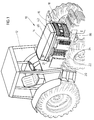
- Fig. 1 an agricultural tractor is indicated, the motor of which is not visible is located in its front area 10 in front of the driver's cab 12.
- the motor is surrounded by cover parts, some of which are shown in the form of an exploded view before their actual assembled position.
- the cover parts are a bonnet 14, a two-part front grill 16, 18 and side panel parts 20, 22, 24.
- the visible side panel parts 20, 22, 24 on the right side of the tractor are a service flap 20, a ventilation grille 22 and a front side part 24.
- the service flap 20 is fastened to a frame 26 shown in FIG. 3 via rear, vertically oriented hinges 21 indicated by an axis 28 in FIG. 2. It can be opened by pulling the handle 29. With the service flap 20 open, service work can be carried out on devices located behind it, such as an oil dipstick, oil refill opening, fuel filter, water separator, locking lever for the opening mechanism of the bonnet 14 and the like.
- the service hatch 20 can be made lockable with a key to prevent unauthorized access.
- the ventilation grille 22 can be fastened to the frame 26 by means of screws 30 which can be screwed into bores 23, only one of which was shown in FIGS. 1 and 2.
- the ventilation grille 22 is arranged behind the radiator 48 of the engine in the direction of travel and contains vertical fins for the cooling air outlet.
- the ventilation grille 22 also serves for security and covers the fan and V-belt of the motor and thus prevents them from touching.
- the front side part 24 is designed such that its lower region can be connected to the frame 26 by insertion. In the upper area, the side part 24 contains locking elements, not shown, by means of which the frame 26 can be fastened quickly.
- the training is carried out so that the front side part 24 is not removable when the hood 14 is closed.
- the front side part 24 can be easily removed if cleaning or maintenance work on the units located behind it, such as radiators, oil coolers, condensers, vehicle batteries and the like, is required.
- the side part 24 has a plurality of openings in its front area, through which cooling air can penetrate into a space enclosed by the front frame part. The openings are selected so that larger impurities and parts of plants are prevented from penetrating.
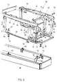
- the frame 26 is box-shaped and, according to FIG. 3, consists of several parts that can be screwed together. These are essentially two rectangular side frame parts 32, 34 arranged laterally next to the motor, which can be screwed together by means of transversely arranged parts Connecting parts are connected to each other. Each side frame part 32, 34 consists of an upper, horizontally extending U-profile 36, a lower, horizontally extending angle profile 38 and three connecting struts 40, 42, 44. These parts are welded together so that the frame side parts 32, 34 during assembly as complete individual parts that require a limited storage space are available.
- the upper U-profile 36 has an outwardly facing surface 46 (FIG. 1) that is visible when the engine cowling is installed and is not covered by any of the cover parts, that is to say neither by the hood 14 nor by a side cowling part 20, 22, 24.
- a type designation of the tractor or the like can be attached to this surface 46 even before final assembly.
- the rear connecting strut 40 essentially represents a U-profile which is open towards the inside of the frame. It carries the hinges 21 for the service flap 20.
- the middle connecting strut 42 also consists of a U-profile which is open towards the inside of the frame.
- the opposite central connecting struts 42 are arranged and designed such that they form perpendicular guide rails in the preassembled frame, into which a cooler 48 (FIG. 5) can be inserted from above. Rubber parts, not shown, are fastened in the guide rails 42, which allow a damped support of the cooler 48.
- the front connecting strut 44 contains connecting means 50 for fastening a lower front grill 52.
- the connecting parts connecting the side frame parts 32, 34 are a cross strut 54, a cross bar 56 and a base plate 58.
- the cross strut 54 is angularly shaped for reasons of stiffening and is fastened to the rear, upper end of the side frame parts 32, 34 by screws 60, only one of which is shown in FIG. 3. It is thus in the assembled state above the engine and immediately in front of the vehicle cabin 12.
- the crossbar 56 is a vertically oriented stiffening plate which can be plugged onto bolts 62 of the central connecting strut 42 from the front and can be fastened to the connecting strut 42 by washers 66 and nuts 64. Screws 68 are also used to fasten the crossbar 56 to the upper side frame parts 32, 34.
- the crossbar 56 has openings 70 which correspond to air passage openings of a cooler 48 which can be mounted behind the crossbar 56. It also contains fasteners for other units, such as the oil cooler 74 and the condenser 76 of an air conditioning system.
- the base plate 58 is trough-shaped in that its side edges are bent upwards.
- the rear side edge 78 of the base plate 58 can be plugged onto bolts 80 of the central connecting struts 42 in the same way as the crossbar 56 and screwed together by nuts 82. Also used for screwing with the lower angle profile 38 screws, which were not shown.
- the front area of the frame 26 is hermetically sealed from below by the base plate 58, so that no cooling air can enter the interior of the frame 26 from here.
- the preassembled frame 26 is largely rigid, dimensionally stable and torsion-resistant.
- the lower angle profiles 38 of the side frame parts 32, 34 and in the base plate 58 there are a total of four bores 86, the positions of which correspond to bolts 90, 92 arranged on a vehicle frame 88 and which serve to fasten the frame 26 to the vehicle frame 88.
- rubber bearings 94 are provided which are fitted onto the bolts 90, 92 before the vehicle frame 88 is assembled.
- the two rear bolts 90 are fastened on spars of the vehicle frame 88 and are at a relatively large distance from one another.
- the two front bolts 92 are fastened on a connecting bridge 96 arranged between the bars.
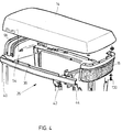
- Fig. 4 the upper region of the frame 26 is shown with the hood 14 above and an upper front grill part 16.
- the two upper U-profiles 36 are connected to one another by an upwardly curved bracket 98.
- the rear area of the bonnet 14 rests on the bracket 98.
- the hood installation axis not shown, about which the front hood area can be pivoted upwards when the engine hood 14 is opened.
- the hood raising mechanism can be of any known design.
- the upper part of a two-part front grill 16 can be fastened by screws 100.
- the hood 14 is thus also the upper front grill 16 raised, so that there is good access to the components housed in the front frame part, which was shown in FIG. 5.
- the lower front grill 52 is hooked onto the front connecting struts 44 of the frame 26.
- the front grill 52 carries protruding screws 102, of which only two are visible in FIG. 5.
- the screw heads are inserted into recesses 50 tapering downwards in the connecting struts 44.
- the screw heads are clamped in the recesses 50.
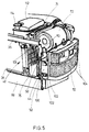
- FIG. 5 shows the arrangement of some units in the front area of the frame 26. Headlights 104 are integrated in the lower front grill 52. The vehicle battery 106 is fastened on the base plate 58. An air filter 72 is attached to the tabs 108 and 110. As already mentioned, a cooler 48 is inserted into the guide, which was formed by the two connecting struts 42, which is covered by the condenser 76 in FIG. 5 and is therefore not visible, but the position of which is indicated by the arrow 48 in FIG. 5 is designated.
- a hood On the rear side of the cooler 48, a hood, not shown, is mounted, which is positively connected to the frame 26.
- the motor fan runs in the scoop.
- the scoop can compensate for relative movements between the frame 26 and the engine, which are caused by twisting of the vehicle frame 88 or vibrations.
- An expansion tank 112 for the coolant with filler opening 114 is fastened above the cooler 48.
- an oil cooler 74 and a condenser 76 of an air conditioning system is mounted on the cross member 56.
- further vehicle components such as horn and hydraulic oil tank, can be arranged in the front area of the frame 26. Very good accessibility to these units is guaranteed. For this purpose, only the bonnet 14 needs to be set up and the front side parts 24 and possibly the lower front grill 52 removed.
- the electrical, hydraulic and other lines of the units are laid in the channels formed by the U-profiles of the frame parts and thus protected against damage.
Landscapes
- Engineering & Computer Science (AREA)
- Chemical & Material Sciences (AREA)
- Combustion & Propulsion (AREA)
- Transportation (AREA)
- Mechanical Engineering (AREA)
- Body Structure For Vehicles (AREA)
- Motor Or Generator Frames (AREA)
- Harvester Elements (AREA)
- Rear-View Mirror Devices That Are Mounted On The Exterior Of The Vehicle (AREA)
- Arrangement Or Mounting Of Propulsion Units For Vehicles (AREA)
- Superstructure Of Vehicle (AREA)
- Cooling, Air Intake And Gas Exhaust, And Fuel Tank Arrangements In Propulsion Units (AREA)
- Fittings On The Vehicle Exterior For Carrying Loads, And Devices For Holding Or Mounting Articles (AREA)
Applications Claiming Priority (2)
| Application Number | Priority Date | Filing Date | Title |
|---|---|---|---|
| DE4105844 | 1991-02-25 | ||
| DE4105844A DE4105844A1 (de) | 1991-02-25 | 1991-02-25 | Verkleidung fuer den motorbereich eines kraftfahrzeuges |
Publications (3)
| Publication Number | Publication Date |
|---|---|
| EP0501276A2 true EP0501276A2 (fr) | 1992-09-02 |
| EP0501276A3 EP0501276A3 (en) | 1993-10-20 |
| EP0501276B1 EP0501276B1 (fr) | 1996-05-01 |
Family
ID=6425817
Family Applications (1)
| Application Number | Title | Priority Date | Filing Date |
|---|---|---|---|
| EP92102642A Expired - Lifetime EP0501276B1 (fr) | 1991-02-25 | 1992-02-18 | Revêtement de l'enveloppe moteur d'un véhicule automobile |
Country Status (8)
| Country | Link |
|---|---|
| US (1) | US5215157A (fr) |
| EP (1) | EP0501276B1 (fr) |
| JP (1) | JPH04317871A (fr) |
| AT (1) | ATE137455T1 (fr) |
| CA (1) | CA2061459C (fr) |
| DE (2) | DE4105844A1 (fr) |
| FI (1) | FI97712C (fr) |
| MX (1) | MX9200797A (fr) |
Cited By (2)
| Publication number | Priority date | Publication date | Assignee | Title |
|---|---|---|---|---|
| EP2650194A3 (fr) * | 2012-04-13 | 2016-12-21 | Joseph Vögele AG | Châssis pour un engin routier |
| EP3162670A4 (fr) * | 2014-06-30 | 2018-03-21 | Yanmar Co., Ltd. | Capot et tracteur comportant un capot |
Families Citing this family (45)
| Publication number | Priority date | Publication date | Assignee | Title |
|---|---|---|---|---|
| JPH07205666A (ja) * | 1994-01-17 | 1995-08-08 | Kubota Corp | 農作業車のボンネット |
| JP3653307B2 (ja) * | 1995-08-21 | 2005-05-25 | 株式会社 神崎高級工機製作所 | ボンネットのロック構造 |
| US5645134A (en) * | 1995-11-14 | 1997-07-08 | Caterpillar Inc. | Engine enclosure assembly |
| EP0906863B1 (fr) * | 1997-10-02 | 2005-03-16 | Kanzaki Kokyukoki Mfg. Co., Ltd. | Système de montage de panneau pour véhicule |
| US6167976B1 (en) | 1998-07-30 | 2001-01-02 | Deere & Company | Engine enclosure |
| DE19936233C2 (de) * | 1999-08-05 | 2003-02-27 | Haegele Gmbh | Wärmetauscheranordnung für selbstfahrende landwirtschaftliche Nutzfahrzeuge |
| JP2001280129A (ja) * | 2000-03-30 | 2001-10-10 | Honda Motor Co Ltd | 車輌用冷却装置 |
| GB2367042A (en) * | 2000-09-26 | 2002-03-27 | New Holland Uk Ltd | Radiator mounting |
| US6487995B2 (en) | 2000-11-30 | 2002-12-03 | Detroit Diesel Corporation | Engine controller and enclosure assembly |
| US20040216934A1 (en) * | 2003-01-27 | 2004-11-04 | Kubota Corporation | Working vehicle having a hood |
| DE102004007602B4 (de) * | 2004-02-17 | 2014-06-18 | Volkswagen Ag | Abdeckung für einen Verbrennungsmotor eines Kraftfahrzeugs |
| US7575081B2 (en) * | 2004-03-29 | 2009-08-18 | Kubota Corporation | Work vehicle |
| US7213667B2 (en) * | 2004-10-29 | 2007-05-08 | Deere & Company | Air intake |
| US7416038B2 (en) * | 2005-02-04 | 2008-08-26 | International Truck Intellectual Property Company, Llc | Tubular hinge bar |
| JP4847073B2 (ja) * | 2005-08-29 | 2011-12-28 | ヤンマー株式会社 | トラクタ |
| JP5332587B2 (ja) * | 2008-12-17 | 2013-11-06 | コベルコ建機株式会社 | 作業機械 |
| US9528447B2 (en) | 2010-09-14 | 2016-12-27 | Jason Eric Green | Fuel mixture control system |
| US8573345B2 (en) * | 2011-02-15 | 2013-11-05 | Deere & Company | Ground level servicing of large work vehicles |
| GB201104158D0 (en) * | 2011-03-11 | 2011-04-27 | Agco Int Gmbh | Engine hood arrangement |
| JP5240324B2 (ja) * | 2011-06-15 | 2013-07-17 | 三菱自動車工業株式会社 | 車両のフード構造 |
| DE102011104931A1 (de) | 2011-06-21 | 2012-12-27 | Daimler Ag | Ausgleichsbehälterabdeckung |
| US9421861B2 (en) | 2011-09-16 | 2016-08-23 | Gaseous Fuel Systems, Corp. | Modification of an industrial vehicle to include a containment area and mounting assembly for an alternate fuel |
| US10086694B2 (en) | 2011-09-16 | 2018-10-02 | Gaseous Fuel Systems, Corp. | Modification of an industrial vehicle to include a containment area and mounting assembly for an alternate fuel |
| US8882071B2 (en) | 2011-09-16 | 2014-11-11 | Jason Green | Modification of an industrial vehicle to include a containment area and mounting assembly for an alternate fuel |
| US9248736B2 (en) | 2011-09-16 | 2016-02-02 | Gaseous Fuel Systems, Corp. | Modification of an industrial vehicle to include a containment area and mounting assembly for an alternate fuel |
| US8820289B2 (en) * | 2011-09-27 | 2014-09-02 | Jason Green | Module containment of fuel control system for a vehicle |
| US8881933B2 (en) | 2011-10-17 | 2014-11-11 | Jason E. Green | Vehicle mounting assembly for a fuel supply |
| US9738154B2 (en) | 2011-10-17 | 2017-08-22 | Gaseous Fuel Systems, Corp. | Vehicle mounting assembly for a fuel supply |
| US9278614B2 (en) | 2011-10-17 | 2016-03-08 | Gaseous Fuel Systems, Corp. | Vehicle mounting assembly for a fuel supply |
| US8783398B2 (en) | 2012-03-02 | 2014-07-22 | Caterpillar Inc. | Replaceable cooling system compartment door screen insert |
| US9157361B2 (en) * | 2012-06-08 | 2015-10-13 | GM Global Technology Operations LLC | Pivoting fluid fill port for a fluid system of a vehicle |
| US9579968B2 (en) * | 2012-11-30 | 2017-02-28 | Cnh Industrial America Llc | One-way vented screen assembly for a work vehicle |
| US9696066B1 (en) | 2013-01-21 | 2017-07-04 | Jason E. Green | Bi-fuel refrigeration system and method of retrofitting |
| US9845744B2 (en) | 2013-07-22 | 2017-12-19 | Gaseous Fuel Systems, Corp. | Fuel mixture system and assembly |
| US9394841B1 (en) | 2013-07-22 | 2016-07-19 | Gaseous Fuel Systems, Corp. | Fuel mixture system and assembly |
| US20150025774A1 (en) | 2013-07-22 | 2015-01-22 | Jason Green | Fuel mixture system and assembly |
| US9446809B2 (en) * | 2013-08-05 | 2016-09-20 | Richard Oneal Sallis | Frame covering device with air vents |
| US9254849B1 (en) | 2014-10-07 | 2016-02-09 | Gaseous Fuel Systems, Corp. | Device and method for interfacing with a locomotive engine |
| US9931929B2 (en) | 2014-10-22 | 2018-04-03 | Jason Green | Modification of an industrial vehicle to include a hybrid fuel assembly and system |
| US9428047B2 (en) | 2014-10-22 | 2016-08-30 | Jason Green | Modification of an industrial vehicle to include a hybrid fuel assembly and system |
| US9885318B2 (en) | 2015-01-07 | 2018-02-06 | Jason E Green | Mixing assembly |
| JP6523824B2 (ja) * | 2015-06-29 | 2019-06-05 | 三菱マヒンドラ農機株式会社 | 作業車両 |
| DE102015112126A1 (de) | 2015-07-24 | 2017-01-26 | Claas Tractor Sas | Landwirtschaftliche Arbeitsmaschine |
| US20210139079A1 (en) * | 2017-06-14 | 2021-05-13 | Agco Corporation | A Panel for an Agricultural Vehicle and an Agricultural Vehicle having such a Panel |
| EP4019372A1 (fr) | 2020-12-24 | 2022-06-29 | AGCO International GmbH | Enceinte de moteur pour machine agricole |
Citations (6)
| Publication number | Priority date | Publication date | Assignee | Title |
|---|---|---|---|---|
| GB488492A (en) * | 1936-12-05 | 1938-07-05 | Leslie Claude Jones | Improvements in and relating to motor vehicles |
| US2833365A (en) * | 1954-09-24 | 1958-05-06 | Deere Mfg Co | Gas engine fuel tank on hood door |
| FR2300006A1 (fr) * | 1975-02-05 | 1976-09-03 | Daimler Benz Ag | Vehicule utilitaire, en particulier tracteur |
| DE2642110A1 (de) * | 1976-09-18 | 1978-03-23 | Kloeckner Humboldt Deutz Ag | Motorhaube fuer fahrzeuge, insbesondere fuer land- und/oder bauwirtschaftlich nutzbare schlepper |
| US4137983A (en) * | 1977-07-11 | 1979-02-06 | Caterpillar Tractor Co. | Sectionalized panel closure |
| US4143733A (en) * | 1977-07-11 | 1979-03-13 | Caterpillar Tractor Co. | Hood panel support structure |
Family Cites Families (10)
| Publication number | Priority date | Publication date | Assignee | Title |
|---|---|---|---|---|
| GB714362A (en) * | 1952-03-20 | 1954-08-25 | Ostler Patents Ltd | Improvements relating to road vehicles |
| US3064748A (en) * | 1961-03-03 | 1962-11-20 | Jacobsen Mfg Co | Combined tractor hood, grille, and instrument panel |
| US4449606A (en) * | 1980-07-18 | 1984-05-22 | Veda, Inc. | Vehicle frame assembly |
| US4572312A (en) * | 1981-08-27 | 1986-02-25 | Case Poclain Corporation Ltd. | Mechanism for enabling a vehicle bonnet to be opened and closed |
| US4506749A (en) * | 1981-12-30 | 1985-03-26 | Allis-Chalmers Corporation | Underhood muffler for tractor |
| US4593786A (en) * | 1982-05-03 | 1986-06-10 | John Tate | Self-contained power supply and support therefor |
| DE8212782U1 (de) * | 1982-05-03 | 1986-02-20 | International Harvester Company Mbh, 4040 Neuss | Klappbare Motorhaube |
| US4491191A (en) * | 1982-12-29 | 1985-01-01 | Allis-Chalmers Corp. | Adjustable tractor grille shell |
| US4735355A (en) * | 1984-10-10 | 1988-04-05 | Mr. Gasket Company | Method for construction of vehicle space frame |
| US4889203A (en) * | 1988-08-12 | 1989-12-26 | J. I. Case Company | Composite engine enclosure |
-
1991
- 1991-02-25 DE DE4105844A patent/DE4105844A1/de not_active Withdrawn
-
1992
- 1992-02-18 DE DE59206147T patent/DE59206147D1/de not_active Expired - Fee Related
- 1992-02-18 AT AT92102642T patent/ATE137455T1/de not_active IP Right Cessation
- 1992-02-18 US US07/837,846 patent/US5215157A/en not_active Expired - Lifetime
- 1992-02-18 EP EP92102642A patent/EP0501276B1/fr not_active Expired - Lifetime
- 1992-02-19 CA CA002061459A patent/CA2061459C/fr not_active Expired - Fee Related
- 1992-02-21 JP JP4034803A patent/JPH04317871A/ja not_active Withdrawn
- 1992-02-21 FI FI920773A patent/FI97712C/fi not_active IP Right Cessation
- 1992-02-25 MX MX9200797A patent/MX9200797A/es not_active IP Right Cessation
Patent Citations (6)
| Publication number | Priority date | Publication date | Assignee | Title |
|---|---|---|---|---|
| GB488492A (en) * | 1936-12-05 | 1938-07-05 | Leslie Claude Jones | Improvements in and relating to motor vehicles |
| US2833365A (en) * | 1954-09-24 | 1958-05-06 | Deere Mfg Co | Gas engine fuel tank on hood door |
| FR2300006A1 (fr) * | 1975-02-05 | 1976-09-03 | Daimler Benz Ag | Vehicule utilitaire, en particulier tracteur |
| DE2642110A1 (de) * | 1976-09-18 | 1978-03-23 | Kloeckner Humboldt Deutz Ag | Motorhaube fuer fahrzeuge, insbesondere fuer land- und/oder bauwirtschaftlich nutzbare schlepper |
| US4137983A (en) * | 1977-07-11 | 1979-02-06 | Caterpillar Tractor Co. | Sectionalized panel closure |
| US4143733A (en) * | 1977-07-11 | 1979-03-13 | Caterpillar Tractor Co. | Hood panel support structure |
Cited By (5)
| Publication number | Priority date | Publication date | Assignee | Title |
|---|---|---|---|---|
| EP2650194A3 (fr) * | 2012-04-13 | 2016-12-21 | Joseph Vögele AG | Châssis pour un engin routier |
| EP2650194B1 (fr) | 2012-04-13 | 2018-10-24 | Joseph Vögele AG | Châssis pour un engin routier |
| EP3162670A4 (fr) * | 2014-06-30 | 2018-03-21 | Yanmar Co., Ltd. | Capot et tracteur comportant un capot |
| US10689039B2 (en) | 2014-06-30 | 2020-06-23 | Yanmar Co., Ltd. | Hood and tractor equipped with hood |
| US11634183B2 (en) | 2014-06-30 | 2023-04-25 | Yanmar Power Technology Co., Ltd. | Hood and tractor equipped with hood |
Also Published As
| Publication number | Publication date |
|---|---|
| MX9200797A (es) | 1993-01-01 |
| EP0501276A3 (en) | 1993-10-20 |
| CA2061459A1 (fr) | 1992-08-26 |
| CA2061459C (fr) | 1995-02-28 |
| FI97712C (fi) | 1997-02-10 |
| ATE137455T1 (de) | 1996-05-15 |
| JPH04317871A (ja) | 1992-11-09 |
| DE4105844A1 (de) | 1992-09-03 |
| DE59206147D1 (de) | 1996-06-05 |
| FI920773A (fi) | 1992-08-26 |
| FI920773A0 (fi) | 1992-02-21 |
| FI97712B (fi) | 1996-10-31 |
| EP0501276B1 (fr) | 1996-05-01 |
| US5215157A (en) | 1993-06-01 |
Similar Documents
| Publication | Publication Date | Title |
|---|---|---|
| EP0501276B1 (fr) | Revêtement de l'enveloppe moteur d'un véhicule automobile | |
| DE4437083C2 (de) | Modulträgerstruktur | |
| EP1707420B1 (fr) | Aménagement d'un radiateur | |
| DE3119572C2 (fr) | ||
| EP1754652B1 (fr) | Câssis du véhicule pour une véhicule utilitaire. | |
| DE4113246A1 (de) | Klimaanlage zum anbau am oder im dach eines fahrzeugs | |
| DE2349912A1 (de) | Fahrerhaus fuer einen auf ketten fahrenden schlepper | |
| EP1698520A1 (fr) | Structure avant de carrosserie avec dispositif de protection de piétons | |
| DE60317284T2 (de) | Frontteil für Motorhaube | |
| DE102018117951A1 (de) | Fahrzeug-Querträger mit verdeckter Strebe für ein Kraftfahrzeug | |
| DE10062686B4 (de) | Klimaanlage für ein Fahrzeug, insbesondere für einen Omnibus | |
| EP2030874B1 (fr) | Poids lourd doté d'une cabine de conducteur spéciale | |
| EP2031341B1 (fr) | Camion avec une cabine de conducteur blindée en construction spéciale | |
| DE102016214827B4 (de) | Kraftfahrzeug mit rahmenartigem Montageträger als Teil einer Karosserie im Front-End-Bereich | |
| EP1503930A1 (fr) | Module de paroi de separation | |
| EP0277293B1 (fr) | Ensemble de plancher pour véhicule, particulièrement pour un véhicule automobile | |
| DE3109976A1 (de) | Erkundungs- und patrouillenfahrzeug | |
| WO2005012066A1 (fr) | Partie avant d'une carrosserie de vehicule automobile | |
| DE102017115544B4 (de) | Fahrzeugverkleidungsstruktur | |
| DE2515927C2 (de) | Fahrzeug mit einer Motorverkleidung | |
| DE102020123289B3 (de) | Energiespeicher-Bodengruppe für einen elektrisch antreibbaren Personenkraftwagen | |
| DE2642110C2 (fr) | ||
| DE10037602B4 (de) | Tragwerk für ein Frontendteil einer Kraftfahrzeugkarosserie | |
| DE102014100795A1 (de) | Frontendmodul für ein Kraftfahrzeug | |
| DE19611191C2 (de) | Fahrzeugvorbau-Seitenstruktur |
Legal Events
| Date | Code | Title | Description |
|---|---|---|---|
| PUAI | Public reference made under article 153(3) epc to a published international application that has entered the european phase |
Free format text: ORIGINAL CODE: 0009012 |
|
| AK | Designated contracting states |
Kind code of ref document: A2 Designated state(s): AT BE CH DE ES FR GB IT LI |
|
| PUAL | Search report despatched |
Free format text: ORIGINAL CODE: 0009013 |
|
| AK | Designated contracting states |
Kind code of ref document: A3 Designated state(s): AT BE CH DE ES FR GB IT LI |
|
| 17P | Request for examination filed |
Effective date: 19930915 |
|
| 17Q | First examination report despatched |
Effective date: 19950725 |
|
| GRAH | Despatch of communication of intention to grant a patent |
Free format text: ORIGINAL CODE: EPIDOS IGRA |
|
| GRAA | (expected) grant |
Free format text: ORIGINAL CODE: 0009210 |
|
| AK | Designated contracting states |
Kind code of ref document: B1 Designated state(s): AT BE CH DE ES FR GB IT LI |
|
| PG25 | Lapsed in a contracting state [announced via postgrant information from national office to epo] |
Ref country code: BE Effective date: 19960501 Ref country code: ES Free format text: THE PATENT HAS BEEN ANNULLED BY A DECISION OF A NATIONAL AUTHORITY Effective date: 19960501 |
|
| REF | Corresponds to: |
Ref document number: 137455 Country of ref document: AT Date of ref document: 19960515 Kind code of ref document: T |
|
| REF | Corresponds to: |
Ref document number: 59206147 Country of ref document: DE Date of ref document: 19960605 |
|
| GBT | Gb: translation of ep patent filed (gb section 77(6)(a)/1977) |
Effective date: 19960606 |
|
| ITF | It: translation for a ep patent filed |
Owner name: LENZI & C. |
|
| ET | Fr: translation filed | ||
| PG25 | Lapsed in a contracting state [announced via postgrant information from national office to epo] |
Ref country code: CH Effective date: 19970228 Ref country code: LI Effective date: 19970228 |
|
| PLBE | No opposition filed within time limit |
Free format text: ORIGINAL CODE: 0009261 |
|
| STAA | Information on the status of an ep patent application or granted ep patent |
Free format text: STATUS: NO OPPOSITION FILED WITHIN TIME LIMIT |
|
| 26N | No opposition filed | ||
| REG | Reference to a national code |
Ref country code: CH Ref legal event code: PL |
|
| REG | Reference to a national code |
Ref country code: GB Ref legal event code: IF02 |
|
| PGFP | Annual fee paid to national office [announced via postgrant information from national office to epo] |
Ref country code: DE Payment date: 20070119 Year of fee payment: 16 |
|
| PGFP | Annual fee paid to national office [announced via postgrant information from national office to epo] |
Ref country code: AT Payment date: 20070201 Year of fee payment: 16 |
|
| PGFP | Annual fee paid to national office [announced via postgrant information from national office to epo] |
Ref country code: GB Payment date: 20070223 Year of fee payment: 16 |
|
| PGFP | Annual fee paid to national office [announced via postgrant information from national office to epo] |
Ref country code: IT Payment date: 20070528 Year of fee payment: 16 |
|
| PGFP | Annual fee paid to national office [announced via postgrant information from national office to epo] |
Ref country code: FR Payment date: 20070221 Year of fee payment: 16 |
|
| GBPC | Gb: european patent ceased through non-payment of renewal fee |
Effective date: 20080218 |
|
| PG25 | Lapsed in a contracting state [announced via postgrant information from national office to epo] |
Ref country code: AT Free format text: LAPSE BECAUSE OF NON-PAYMENT OF DUE FEES Effective date: 20080218 |
|
| REG | Reference to a national code |
Ref country code: FR Ref legal event code: ST Effective date: 20081031 |
|
| PG25 | Lapsed in a contracting state [announced via postgrant information from national office to epo] |
Ref country code: DE Free format text: LAPSE BECAUSE OF NON-PAYMENT OF DUE FEES Effective date: 20080902 |
|
| PG25 | Lapsed in a contracting state [announced via postgrant information from national office to epo] |
Ref country code: FR Free format text: LAPSE BECAUSE OF NON-PAYMENT OF DUE FEES Effective date: 20080229 |
|
| PG25 | Lapsed in a contracting state [announced via postgrant information from national office to epo] |
Ref country code: GB Free format text: LAPSE BECAUSE OF NON-PAYMENT OF DUE FEES Effective date: 20080218 |
|
| PG25 | Lapsed in a contracting state [announced via postgrant information from national office to epo] |
Ref country code: IT Free format text: LAPSE BECAUSE OF NON-PAYMENT OF DUE FEES Effective date: 20080218 |