EP0482641B1 - Bilderzeugungsvorrichtung - Google Patents
Bilderzeugungsvorrichtung Download PDFInfo
- Publication number
- EP0482641B1 EP0482641B1 EP91118163A EP91118163A EP0482641B1 EP 0482641 B1 EP0482641 B1 EP 0482641B1 EP 91118163 A EP91118163 A EP 91118163A EP 91118163 A EP91118163 A EP 91118163A EP 0482641 B1 EP0482641 B1 EP 0482641B1
- Authority
- EP
- European Patent Office
- Prior art keywords
- polygon mirror
- image forming
- forming apparatus
- rotation
- Prior art date
- Legal status (The legal status is an assumption and is not a legal conclusion. Google has not performed a legal analysis and makes no representation as to the accuracy of the status listed.)
- Expired - Lifetime
Links
Images


Classifications
-
- G—PHYSICS
- G06—COMPUTING; CALCULATING OR COUNTING
- G06K—GRAPHICAL DATA READING; PRESENTATION OF DATA; RECORD CARRIERS; HANDLING RECORD CARRIERS
- G06K15/00—Arrangements for producing a permanent visual presentation of the output data, e.g. computer output printers
- G06K15/02—Arrangements for producing a permanent visual presentation of the output data, e.g. computer output printers using printers
- G06K15/12—Arrangements for producing a permanent visual presentation of the output data, e.g. computer output printers using printers by photographic printing, e.g. by laser printers
-
- B—PERFORMING OPERATIONS; TRANSPORTING
- B41—PRINTING; LINING MACHINES; TYPEWRITERS; STAMPS
- B41J—TYPEWRITERS; SELECTIVE PRINTING MECHANISMS, i.e. MECHANISMS PRINTING OTHERWISE THAN FROM A FORME; CORRECTION OF TYPOGRAPHICAL ERRORS
- B41J2/00—Typewriters or selective printing mechanisms characterised by the printing or marking process for which they are designed
- B41J2/435—Typewriters or selective printing mechanisms characterised by the printing or marking process for which they are designed characterised by selective application of radiation to a printing material or impression-transfer material
- B41J2/47—Typewriters or selective printing mechanisms characterised by the printing or marking process for which they are designed characterised by selective application of radiation to a printing material or impression-transfer material using the combination of scanning and modulation of light
- B41J2/471—Typewriters or selective printing mechanisms characterised by the printing or marking process for which they are designed characterised by selective application of radiation to a printing material or impression-transfer material using the combination of scanning and modulation of light using dot sequential main scanning by means of a light deflector, e.g. a rotating polygonal mirror
-
- G—PHYSICS
- G06—COMPUTING; CALCULATING OR COUNTING
- G06K—GRAPHICAL DATA READING; PRESENTATION OF DATA; RECORD CARRIERS; HANDLING RECORD CARRIERS
- G06K15/00—Arrangements for producing a permanent visual presentation of the output data, e.g. computer output printers
- G06K15/02—Arrangements for producing a permanent visual presentation of the output data, e.g. computer output printers using printers
- G06K15/12—Arrangements for producing a permanent visual presentation of the output data, e.g. computer output printers using printers by photographic printing, e.g. by laser printers
- G06K15/1204—Arrangements for producing a permanent visual presentation of the output data, e.g. computer output printers using printers by photographic printing, e.g. by laser printers involving the fast moving of an optical beam in the main scanning direction
- G06K15/1209—Intensity control of the optical beam
-
- G—PHYSICS
- G06—COMPUTING; CALCULATING OR COUNTING
- G06K—GRAPHICAL DATA READING; PRESENTATION OF DATA; RECORD CARRIERS; HANDLING RECORD CARRIERS
- G06K15/00—Arrangements for producing a permanent visual presentation of the output data, e.g. computer output printers
- G06K15/02—Arrangements for producing a permanent visual presentation of the output data, e.g. computer output printers using printers
- G06K15/12—Arrangements for producing a permanent visual presentation of the output data, e.g. computer output printers using printers by photographic printing, e.g. by laser printers
- G06K15/1204—Arrangements for producing a permanent visual presentation of the output data, e.g. computer output printers using printers by photographic printing, e.g. by laser printers involving the fast moving of an optical beam in the main scanning direction
- G06K15/1219—Detection, control or error compensation of scanning velocity or position, e.g. synchronisation
Definitions
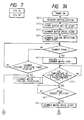
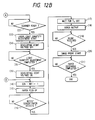
- the reason why the development and transfer at (n1) is performed after the completion of light quantity adjustment is that a latent image on the photosensitive drum 1 caused by the laser light emitted in adjusting the light quantity is prevented from developing and the transfer roller is not made dirty. Accordingly, this can be also achieved with another method in which the development and transfer is once set up before the adjustment of light quantity, and the high voltage for development is turned off for a period corresponding to the position of the photosensitive drum for which the light quantity adjustment has been made.
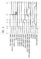
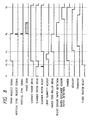
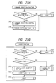
- the timing chart for the former is shown in Fig. 8, while that for the latter is shown in Fig. 9.
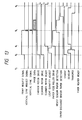
- the image signal VIDEO is a composite signal based on a timing signal for lighting up the laser to obtain an image input signal from the controller, a light-up control signal for operating the laser APC as described below, and a synchronizing signal BD which is a beam detection signal at a predetermined position in a main scan direction.
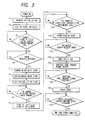
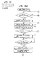
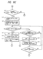
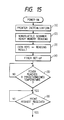
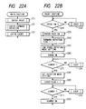
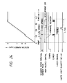
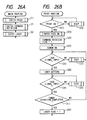
- step (7) determines whether or not the timer B is counted down (12). And it is checked again whether or not the rock on signal ROCK ON is in the ON state (13), in which if the answer is YES, namely, in the set-up characteristics as shown in Fig. 17B, it is checked whether or not the timer B is at the time-up (14). And if the answer is NO, the ESCP processing routine is executed (15), while if the answer is YES, the scanner is judged to be in the ready state (16), and the transfer to subsequent print sequence is made. Also, in the set-up characteristics as shown in Fig. 17A, the transfer to step (16) is immediately made, because the extended time is 0.
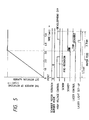
- the determining means is provided with monitor means for monitoring a scan speed state signal output from the detecting means for a predetermined period, and count means for counting up the scan speed out-of-range time of the scan optical system by monitoring the output of detecting means while the monitor means monitors the scan speed state signal, thereby determining any scan speed stabilization time based on a count value counted up by the count means, so that any scan speed stabilization time corresponding to the scan speed out-of-range time can be determined.
- the detecting means detects a changing condition of the scan speed from that of the electric power to be supplied to the scan optical system, a more precise detection is allowed, whereby the scan speed stabilization time can be calculated at optimum. Accordingly, even if the set-up characteristics of the scan optical system may be changed with the service condition or variation with the passage of time, it is always possible to determine an optimal smallest scan speed stabilization time, thereby exhibiting an excellent effect of largely shortening the first print time as compared with a conventional one.
- the present invention is easily applicable to a case where the image is recorded with the resolution corresponding to any of set resolutions, for example, 240, 300, 400, 600 (DPI (dot per inch)), in the recording apparatus having resolution switching means capable of switching the image density easily.
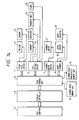
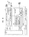
- This switching of resolution is carried out by switching the resolution in the main scan direction easily with the CPU 101 which changes the frequency dividing ratio for the variable multistage frequency divider circuit 141 as shown in Fig. 16.
- variable multistage frequency divider circuit 141 and the frequency divider changeover circuit 142 of the gate array 104 are unnecessary with the operation, but may be provided for other operations.
- monitor means for monitoring a predetermined state signal varying with the drive of the scan optical system
- directing means for directing a judgment of whether the scan speed of the scan optical system reaches a first scan speed set for writing the image or a second scan speed set at a lower speed than the first scan speed, based on the output of the monitor means
- authorization means for authorizing the light quantity adjustment with the light quantity adjusting means, at the time when the second scan speed is reached, as directed by the directing means, so that the light quantity adjustment can be performed in parallel with the set-up of the scan optical system by detecting that the scan speed of the scan optical system reaches a second scan speed, without largely changing the constitution of a conventional scan optical system.
Landscapes
- Physics & Mathematics (AREA)
- Engineering & Computer Science (AREA)
- Optics & Photonics (AREA)
- General Engineering & Computer Science (AREA)
- General Physics & Mathematics (AREA)
- Theoretical Computer Science (AREA)
- Laser Beam Printer (AREA)
- Facsimile Scanning Arrangements (AREA)
- Control Or Security For Electrophotography (AREA)
- Mechanical Optical Scanning Systems (AREA)
Claims (26)
- Bilderzeugungsvorrichtung zum Abtasten mit einem entsprechend einer Bildinformation modulierten Lichtstrahl mittels eines drehbaren Polygonspiegels (3), mit:dadurch gekennzeichnet, daßeiner Lichtstrahlerzeugungseinrichtung (2) zum Erzeugen des Lichtstrahls;einer Einstelleinrichtung (29) zum Einstellen der Lichtmenge des durch die Lichtstrahlerzeugungseinrichtung (2) erzeugten Lichtstrahls;einer Ansteuereinrichtung (19, 27) zum Ansteuern des drehbaren Polygonspiegels (3) während der Drehung; undeiner Erfassungseinrichtung (19) zum Erfassen, ob die Drehzahl des drehbaren Polygonspiegels (3) innerhalb einer vorbestimmten Zeitdauer eine vorbestimmte Drehzahl erreicht hat oder nicht,
die Lichtmengeneinstelleinrichtung (29) die Lichtmengeneinstellung nach dem Beginn des Ansteuerns des drehbaren Polygonspiegels (3) mittels der Ansteuereinrichtung (19, 27) und vor dem Erreichen der vorbestimmten Drehzahl durch die Drehzahl des drehbaren Polygonspiegels (3) started. - Bilderzeugungsvorrichtung nach Anspruch 1,
gekennzeichnet durch
eine Speichereinrichtung (30; 32) zum Speichern eines Erfassungsergebnisses der Erfassungseinrichtung (19). - Bilderzeugungsvorrichtung zum Abtasten mit einem entsprechend einer Bildinformation modulierten Lichtstrahl mittels eines drehbaren Polygonspiegels (3), mit:gekennzeichnet durcheiner Lichtstrahlerzeugungseinrichtung (2) zum Erzeugen des Lichtstrahls;einer Ansteuereinrichtung (19, 27) zum Ansteuern des drehbaren Polygonspiegels (3) während der Drehung; undeiner Erfassungseinrichtung (19) zum Erfassen, ob die Drehzahl des drehbaren Polygonspiegels (3) eine vorbestimmte Drehzahl innerhalb einer vorbestimmten Zeitdauer erreicht hat;
eine Speichereinrichtung (30; 32) zum Speichern eines Erfassungsergebnisses der Erfassungseinrichtung (19), wobei die Erfassung im Ansprechen auf das gespeicherte Erfassungsergebnis ausgelassen wird. - Bilderzeugungsvorrichtung nach Anspruch 3,
gekennzeichnet durch
eine Einstelleinrichtung (29) zum Einstellen der Lichtmenge des durch die Lichtstrahlerzeugungseinrichtung (2) erzeugten Lichtstrahls, wobei die Einstelleinrichtung (29) die Lichtmengeneinstellung entsprechend eines Speicherinhalts der Speichereinrichtung (30; 32) nach dem Ansteuerbeginn des drehbaren Polygonspiegels (3) durch die Ansteuereinrichtung (19, 27) und vor dem Erreichen der vorbestimmten Drehzahl durch die Drehzahl des drehbaren Polygonspiegels (3) startet. - Bilderzeugungsvorrichtung nach Anspruch 1 oder 4,
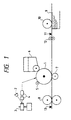
gekennzeichnet durchein fotoempfindliches Element (1), auf dem ein Latentbild durch Abtasten mit dem durch den drehbaren Polygonspiegel (3) abgelenkten Lichtstrahl gebildet wird;einer Entwicklungseinrichtung (6, 24) zum Sichtbarmachen des auf dem fotoempfindlichen Element gebildeten Latentbilds; und eine Transfereinrichtung (7, 25) zum Übertragen eines auf dem fotoempfindlichen Element (1) befindlichen sichtbaren Bilds auf ein Aufzeichnungsblatt;wobei die Vorrichtung zumindest eine der Entwicklungseinrichtung (7, 25) oder der Transfereinrichtung (7, 25) so steuert, daß die Entwicklung oder Übertragung nicht für das auf dem fotoempfindlichen Element (1) bei der Lichtmengeneinstellung durch die Lichtmengeneinstelleinrichtung (29) gebildete Latentbild erfolgt. - Bilderzeugungsvorrichtung nach Anspruch 2 oder 3,
dadurch gekennzeichnet, daß
die Speichereinrichtung (30; 32) ein Erfassungsergebnis der Erfassungseinrichtung (19) beim Ansteuern des drehbaren Polygonspiegels (3) durch die Ansteuereinrichtung (19, 27) während der Drehung speichert, wenn die Versorgung der Vorrichtung eingeschaltet ist. - Bilderzeugungsvorrichtung nach Anspruch 2 oder 3,
dadurch gekennzeichnet, daß
die Vorrichtung den drehbaren Polygonspiegel (3) während dessen Drehung mittels der Ansteuereinrichtung (19, 27) in vorbestimmten Intervallen zumindest in einem Bereitschaftszustand ansteuert und das Erfassungsergebnis der Erfassungseinrichtung (19) in der Speichereinrichtung (30; 32) speichert. - Bilderzeugungsvorrichtung nach Anspruch 2 oder 3,
dadurch gekennzeichnet, daß
die Ansteuereinrichtung (19, 27) die Drehansteuerung des drehbaren Polygonspiegels (3) im Ansprechen auf ein von einer Einrichtung zum Erzeugen der Bildinformation ausgegebenes Druckanforderungssignal startet. - Bilderzeugungsvorrichtung nach Anspruch 2 oder 8,
gekennzeichnet durcheine Lagereinrichtung (9) zum Lagern einer Vielzahl von Aufzeichnungsblättern, auf denen ein Bild aufgezeichnet wird; undeine Zuführeinrichtung (10) zum blattweisen Zuführen der in der Lagereinrichtung (9) gelagerten Aufzeichnungsblätter;wobei die Zuführeinrichtung (10) die Zuführoperation vor dem Druckanforderungssignal startet, wenn das erfaßte Ergebnis, daß der drehbare Polygonspiegel (3) eine vorbestimmte Drehzahl innerhalb einer vorbestimmten Zeitdauer erreicht hat, in der Speichereinrichtung (30; 32) gespeichert ist. - Bilderzeugungsvorrichtung nach Anspruch 8,
dadurch gekennzeichnet, daß
die Vorrichtung ein Erfassungsergebnis der Erfassungseinrichtung (19) beim Ansteuern des drehbaren Polygonspiegels (3) während dessen Drehung im Ansprechen auf ein Druckanforderungssignal in der Speichereinrichtung (30; 32) speichert. - Bilderzeugungsvorrichtung nach Anspruch 1 oder 3,
gekennzeichnet durch
eine nichtflüchtige Speichereinrichtung (32) zum Speichern des Erfassungsergebnisses der Erfassungseinrichtung (19). - Bilderzeugungsvorrichtung zum Abtasten mit einem entsprechend einer Bildinformations modulierten Lichtstrahl mittels eines drehbaren Polygonspiegels (3) mit:gekennzeichnet durcheiner Ansteuereinrichtung (19, 27) zum Ansteuern des drehbaren Polygonspiegels (3) während der Drehung; undeiner Erfassungseinrichtung (19) zum Erfassen, ob die Drehzahl des drehbaren Polygonspiegels (3) innerhalb einer vorbestimmten Zeitdauer eine vorbestimmte Drehzahl erreicht hat;
eine Bestimmungseinrichtung zum Bestimmen der abgelaufenen Zeitdauer bis die Drehzahl des drehbaren Polygonspiegels als stabil betrachtet wird, nachdem die Erfassungseinrichtung (19) feststellt, daß die Drehzahl des drehbaren Polygonspiegels (3) eine vorbestimmte Drehzahl erreicht hat. - Bilderzeugungsvorrichtung nach Anspruch 12,
gekennzeichnet durcheine Eingabeeinrichtung zum Eingeben der durch eine externe Vorrichtung gesendeten Bildinformation; undeine Ausgabeeinrichtung zum Ausgeben eines Signals, das den Zustand angibt, in dem die Bildinformation eingegeben werden kann, wenn die durch die Bestimmungseinrichtung bestimmte Zeit abgelaufen ist. - Bilderzeugungsvorrichtung nach Anspruch 12,
dadurch gekennzeichnet, daß
die Erfassungseinrichtung (19) erfaßt, daß die Drehzahl des drehbaren Polygonspiegels (3) innerhalb eines vorbestimmten Bereichs liegt, und daß die Bestimmungseinrichtung die Zeitdauer, nach der die Drehzahl des drehbaren Polygonspiegels (3) als stabil betrachtet wird, bestimmt, nachdem die Drehzahl des drehbaren Polygonspiegels (3) einen vorbestimmten Drehzahlbereichs erreicht hat. - Bilderzeugungsvorrichtung nach Anspruch 14,
dadurch gekennzeichnet, daß
die durch die Bestimmungseinrichtung bestimmte Zeitdauer basierend auf einem Erfassungsergebnis der Erfassungseinrichtung (19) für eine vorbestimmte Überwachungszeit bestimmt wird, nachdem die Drehzahl des drehbaren Polygonspiegels (3) einen vorbestimmten Bereich erreicht hat. - Bilderzeugungsvorrichtung nach Anspruch 15,
dadurch gekennzeichnet, daß
die durch die Bestimmungseinrichtung bestimmte Zeitdauer innerhalb der Überwachungszeit und entsprechend der Zeit bestimmt wird, während der sich die Drehzahl des drehbaren Polygonspiegels (3) außerhalb des vorbestimmten Bereichs befindet. - Bilderzeugungsvorrichtung nach Anspruch 15,
dadurch gekennzeichnet, daß
die Überwachungszeit basierend auf der für die Überwachungszeit erfaßten Ausgabe der Erfassungseinrichtung (19) verlängert wird. - Bilderzeugungsvorrichtung nach Anspruch 16,
dadurch gekennzeichnet, daß
die Vorrichtung eine Fehlerverarbeitung innerhalb der Überwachungszeit durchführt, wenn ein aufsummierter Wert der Zeit, während der sich die Drehzahl des drehbaren Polygonspiegels (3) außerhalb des vorbestimmten Bereichs befindet, einen vorbestimmten Wert überschreitet. - Bilderzeugungsvorrichtung nach Anspruch 16,
dadurch gekennzeichnet, daß
die Ansteuervorrichtung (19, 27) den drehbaren Polygonspiegel (3) während dessen Drehung mittels eines Phasenregelschleifenverfahrens ansteuert, und die Erfassungseinrichtung (19) erfaßt, ob die Phase verriegelt ist oder nicht. - Bilderzeugungsvorrichtung nach Anspruch 14,
dadurch gekennzeichnet, daß
die Erfassungseinrichtung (19) basierend auf einer der Ansteuereinrichtung zugeführten Versorgungsleistung erfaßt, daß sich die Drehzahl des drehbaren Polygonspiegels (3) innerhalb eines vorbestimmten Bereichs befindet. - Bilderzeugungsvorrichtung nach Anspruch 14,
dadurch gekennzeichnet, daß
die durch die Bestimmungseinrichtung bestimmte Zeitdauer beendet ist, wenn die Zeitdauer, während der sich die Drehzahl des drehbaren Polygonspiegels (3) innerhalb eines vorbestimmten Bereichs befindet, eine vorbestimmte Zeitdauer erreicht. - Bilderzeugungsvorrichtung nach Anspruch 1,
dadurch gekennzeichnet, daß
die Lichtmengeneinstelleinrichtung (29) mit der Lichtmengeneinstellung beginnen kann, wenn erfaßt wird, daß sich der drehbare Polygonspiegel (3) mit einer ersten Drehzahl dreht, selbst wenn sich der drehbare Polygonspiegel (3) mit einer gegenüber der ersten Drehzahl höheren zweiten Drehzahl drehen sollte, nach dem Beginn des Ansteuerns des drehbaren Polygonspiegels (3) mittels der Ansteuereinrichtung. - Bilderzeugungsvorrichtung nach Anspruch 22,
dadurch gekennzeichnet, daß
der drehbare Polygonspiegel (3) während dessen Drehung stabil in der ersten und zweiten Drehzahl betrieben werden kann. - Bilderzeugungsvorrichtung nach Anspruch 23,
dadurch gekennzeichnet, daß
die Vorrichtung die Bilderzeugung mit zwei verschiedenen ersten und zweiten Auflösungen durchführen kann, wobei die erste und zweite Drehzahl der ersten bzw. zweiten Auflösung entsprechen. - Bilderzeugungsvorrichtung nach Anspruch 22, 23 oder 24,
dadurch gekennzeichnet, daß
die Erfassungseinrichtung (19) einen Strahldetektor zum Erfassen des durch den drehbaren Spiegel (3) abgelenkten Lichtstrahls an einer vorbestimmten Position aufweist, und basierend auf der Ausgabe des Strahldetektors erfaßt, daß der drehbare Polygonspiegel (3) zumindest mit der ersten Drehzahl gedreht wird. - Bilderzeugungsvorrichtung nach Anspruch 22, 23 oder 24,
dadurch gekennzeichnet, daß
die Ansteuereinrichtungen (19, 27) eine Tachosignalerzeugungseinrichtung aufweist, wobei die Erfassungseinrichtung (19) basierend auf der Frequenz des Tachosignals erfaßt, daß sich der drehbare Polygonspiegel (3) zumindest mit der ersten Drehzahl dreht.
Applications Claiming Priority (8)
| Application Number | Priority Date | Filing Date | Title |
|---|---|---|---|
| JP2289339A JPH04167657A (ja) | 1990-10-26 | 1990-10-26 | 画像形成装置 |
| JP289339/90 | 1990-10-26 | ||
| JP45608/91 | 1991-02-20 | ||
| JP3045606A JPH04265761A (ja) | 1991-02-20 | 1991-02-20 | 記録装置 |
| JP45606/91 | 1991-02-20 | ||
| JP3045608A JPH04265762A (ja) | 1991-02-20 | 1991-02-20 | 記録装置 |
| JP3080476A JPH04292067A (ja) | 1991-03-20 | 1991-03-20 | 画像形成装置 |
| JP80476/91 | 1991-03-20 |
Publications (3)
| Publication Number | Publication Date |
|---|---|
| EP0482641A2 EP0482641A2 (de) | 1992-04-29 |
| EP0482641A3 EP0482641A3 (en) | 1993-08-18 |
| EP0482641B1 true EP0482641B1 (de) | 1998-05-27 |
Family
ID=27461739
Family Applications (1)
| Application Number | Title | Priority Date | Filing Date |
|---|---|---|---|
| EP91118163A Expired - Lifetime EP0482641B1 (de) | 1990-10-26 | 1991-10-24 | Bilderzeugungsvorrichtung |
Country Status (4)
| Country | Link |
|---|---|
| US (2) | US5550573A (de) |
| EP (1) | EP0482641B1 (de) |
| KR (1) | KR950000390B1 (de) |
| DE (1) | DE69129488T2 (de) |
Families Citing this family (23)
| Publication number | Priority date | Publication date | Assignee | Title |
|---|---|---|---|---|
| US6064419A (en) * | 1994-12-28 | 2000-05-16 | Canon Kabushiki Kaisha | Timings of rotational speed in a laser beam printer |
| US5864355A (en) * | 1997-03-20 | 1999-01-26 | Lexmark International, Inc. | Image forming apparatus with laser calibration during ramp-up period of an optical device |
| JP2000203082A (ja) * | 1999-01-13 | 2000-07-25 | Ricoh Co Ltd | 画像形成装置 |
| JP2001096804A (ja) * | 1999-07-23 | 2001-04-10 | Canon Inc | 画像出力装置及びその制御方法 |
| JP4497689B2 (ja) | 1999-10-01 | 2010-07-07 | キヤノン株式会社 | 印刷装置、交換ユニット、及び、メモリユニット |
| US6252618B1 (en) | 2000-06-15 | 2001-06-26 | Lexmark International, Inc. | Method of controlling print registration in an electrophotographic machine |
| JP2002023570A (ja) | 2000-07-13 | 2002-01-23 | Canon Inc | 画像形成装置およびその装置ユニット |
| US6285383B1 (en) | 2000-09-14 | 2001-09-04 | Lexmark International, Inc. | Method of controlling laser scanner phase in a multicolor electrophotographic machine |
| JP2002139807A (ja) * | 2000-10-31 | 2002-05-17 | Fuji Photo Film Co Ltd | 表示装置、表示方法及び画像処理システム |
| US6570604B2 (en) | 2001-04-16 | 2003-05-27 | Lexmark International, Inc. | Mode dependent time to begin printing |
| US6459443B1 (en) | 2001-06-21 | 2002-10-01 | Lexmark International, Inc | Method of minimizing print delay due to mirror motor warm-up in an electrophotographic machine |
| JP3765473B2 (ja) * | 2001-08-24 | 2006-04-12 | リコープリンティングシステムズ株式会社 | レーザ制御装置および電子写真装置 |
| JP3791600B2 (ja) * | 2002-01-11 | 2006-06-28 | リコープリンティングシステムズ株式会社 | 電子写真装置 |
| KR100472474B1 (ko) * | 2002-08-30 | 2005-03-10 | 삼성전자주식회사 | 전자사진 프로세서의 현상제 절약방법 및 이를 수행하는전자사진 프로세서 |
| JP4407160B2 (ja) * | 2003-05-16 | 2010-02-03 | コニカミノルタビジネステクノロジーズ株式会社 | 画像形成装置 |
| US7158163B2 (en) * | 2004-03-22 | 2007-01-02 | Kabushiki Kaisha Toshiba | Light beam scanning apparatus capable of shortening the standby time and image forming apparatus capable of shortening the standby time |
| JP4419072B2 (ja) * | 2004-11-05 | 2010-02-24 | ブラザー工業株式会社 | 画像形成装置及びそのプログラム |
| JP4687962B2 (ja) * | 2005-07-27 | 2011-05-25 | ブラザー工業株式会社 | 画像形成装置 |
| US20070216758A1 (en) * | 2006-03-14 | 2007-09-20 | Kyocera Mita Corporation | Driving control device, image forming apparatus and recording medium for recording driving control program |
| US20100048752A1 (en) * | 2008-08-21 | 2010-02-25 | Nova Chemicals Inc. | Crosslinked polymer composition |
| US8053525B2 (en) * | 2009-06-24 | 2011-11-08 | Nova Chemicals Inc. | Method of modifying the rheology of a thermoplastic resin |
| WO2015159992A1 (en) * | 2014-04-15 | 2015-10-22 | Canon Kabushiki Kaisha | Image forming apparatus |
| US9400444B2 (en) * | 2014-04-15 | 2016-07-26 | Canon Kabushiki Kaisha | Image forming apparatus with improved timing for emitting beam detect light beam |
Family Cites Families (12)
| Publication number | Priority date | Publication date | Assignee | Title |
|---|---|---|---|---|
| JPS6024624B2 (ja) * | 1977-04-07 | 1985-06-13 | 富士写真フイルム株式会社 | 光ビ−ム走査方法 |
| US4270131A (en) * | 1979-11-23 | 1981-05-26 | Tompkins E Neal | Adaptive error correction device for a laser scanner |
| US4613877A (en) * | 1984-11-26 | 1986-09-23 | Data Recording Systems, Inc. | High resolution laser printer |
| JPS6320157U (de) * | 1986-07-21 | 1988-02-09 | ||
| JP2565879B2 (ja) * | 1986-10-27 | 1996-12-18 | ミノルタ 株式会社 | レ−ザプリンタ |
| US4862288A (en) * | 1986-10-27 | 1989-08-29 | Minolta Camera Kabushiki Kaisha | Printing apparatus with plural density control |
| US4872025A (en) * | 1987-03-30 | 1989-10-03 | Minolta Camera Kabushiki Kaisha | Laser printer capable of changing a pixel density |
| JP2675811B2 (ja) * | 1988-04-20 | 1997-11-12 | キヤノン株式会社 | 光ビームプリンタ |
| JP2925548B2 (ja) * | 1988-05-13 | 1999-07-28 | キヤノン株式会社 | 記録装置 |
| JPH03202807A (ja) * | 1989-12-28 | 1991-09-04 | Toshiba Corp | レーザ発振器の光量制御装置 |
| US5258779A (en) * | 1990-02-17 | 1993-11-02 | Canon Kabushiki Kaisha | Image forming apparatus with means for controlling feeding of recording medium |
| US5083140A (en) * | 1990-04-10 | 1992-01-21 | Minnesota Mining And Manufacturing Company | Multiple charge images initiation with scan synchronization |
-
1991
- 1991-10-24 DE DE69129488T patent/DE69129488T2/de not_active Expired - Fee Related
- 1991-10-24 EP EP91118163A patent/EP0482641B1/de not_active Expired - Lifetime
- 1991-10-26 KR KR1019910018950A patent/KR950000390B1/ko not_active IP Right Cessation
-
1994
- 1994-11-30 US US08/351,107 patent/US5550573A/en not_active Expired - Fee Related
-
1995
- 1995-06-07 US US08/471,865 patent/US5883659A/en not_active Expired - Fee Related
Also Published As
| Publication number | Publication date |
|---|---|
| DE69129488D1 (de) | 1998-07-02 |
| DE69129488T2 (de) | 1998-11-12 |
| EP0482641A3 (en) | 1993-08-18 |
| KR950000390B1 (ko) | 1995-01-16 |
| KR920008684A (ko) | 1992-05-28 |
| US5883659A (en) | 1999-03-16 |
| EP0482641A2 (de) | 1992-04-29 |
| US5550573A (en) | 1996-08-27 |
Similar Documents
| Publication | Publication Date | Title |
|---|---|---|
| EP0482641B1 (de) | Bilderzeugungsvorrichtung | |
| US5043745A (en) | Light intensity control apparatus | |
| US5610646A (en) | Image forming apparatus having improved resolution switching capabilities | |
| JP2001091872A (ja) | ビーム光走査装置 | |
| US7602410B2 (en) | Apparatus for and method of forming image using oscillation mirror | |
| EP0581259B1 (de) | Bilderzeugungsgerät und Vorrichtung für die Steuerung der Lichtmenge zur Verwendung in diesem Gerät | |
| US5159184A (en) | Apparatus for controlling the intensity of a laser beam emitted from a semiconductor laser unit | |
| EP0304276B1 (de) | Strahlaufzeichnungsgerät | |
| US5130524A (en) | Apparatus for controlling intensity of laser beam emitted from semiconductor laser unit | |
| KR100372122B1 (ko) | 화상 형성 장치 | |
| US20050231781A1 (en) | Apparatus for and method of forming image using oscillation mirror | |
| US5745154A (en) | Digital image forming apparatus with scan synchronization | |
| JPH0698104A (ja) | Ld駆動回路およびシェーディング補正方法 | |
| JPH11105335A (ja) | 画像形成装置と半導体レーザーapc回路 | |
| JPH0245170A (ja) | 高精度画像記録装置 | |
| JPH0664219A (ja) | 画像形成装置 | |
| JP3710389B2 (ja) | 画像形成装置 | |
| JP2875411B2 (ja) | プリンタ装置 | |
| JP3596970B2 (ja) | 光ビーム走査装置 | |
| JP3563930B2 (ja) | 画像形成装置 | |
| JPH07306626A (ja) | 画像形成装置 | |
| JPH05328075A (ja) | 画像形成装置 | |
| JPH06127089A (ja) | 画像形成装置 | |
| JP2001324688A (ja) | 画像形成用の光走査装置および光走査方法 | |
| JPH04167657A (ja) | 画像形成装置 |
Legal Events
| Date | Code | Title | Description |
|---|---|---|---|
| PUAI | Public reference made under article 153(3) epc to a published international application that has entered the european phase |
Free format text: ORIGINAL CODE: 0009012 |
|
| AK | Designated contracting states |
Kind code of ref document: A2 Designated state(s): DE FR GB IT |
|
| PUAL | Search report despatched |
Free format text: ORIGINAL CODE: 0009013 |
|
| AK | Designated contracting states |
Kind code of ref document: A3 Designated state(s): DE FR GB IT |
|
| 17P | Request for examination filed |
Effective date: 19940104 |
|
| 17Q | First examination report despatched |
Effective date: 19960716 |
|
| GRAG | Despatch of communication of intention to grant |
Free format text: ORIGINAL CODE: EPIDOS AGRA |
|
| GRAG | Despatch of communication of intention to grant |
Free format text: ORIGINAL CODE: EPIDOS AGRA |
|
| GRAG | Despatch of communication of intention to grant |
Free format text: ORIGINAL CODE: EPIDOS AGRA |
|
| GRAH | Despatch of communication of intention to grant a patent |
Free format text: ORIGINAL CODE: EPIDOS IGRA |
|
| GRAG | Despatch of communication of intention to grant |
Free format text: ORIGINAL CODE: EPIDOS AGRA |
|
| GRAH | Despatch of communication of intention to grant a patent |
Free format text: ORIGINAL CODE: EPIDOS IGRA |
|
| GRAH | Despatch of communication of intention to grant a patent |
Free format text: ORIGINAL CODE: EPIDOS IGRA |
|
| GRAA | (expected) grant |
Free format text: ORIGINAL CODE: 0009210 |
|
| AK | Designated contracting states |
Kind code of ref document: B1 Designated state(s): DE FR GB IT |
|
| REF | Corresponds to: |
Ref document number: 69129488 Country of ref document: DE Date of ref document: 19980702 |
|
| ITF | It: translation for a ep patent filed |
Owner name: SOCIETA' ITALIANA BREVETTI S.P.A. |
|
| ET | Fr: translation filed | ||
| PLBE | No opposition filed within time limit |
Free format text: ORIGINAL CODE: 0009261 |
|
| STAA | Information on the status of an ep patent application or granted ep patent |
Free format text: STATUS: NO OPPOSITION FILED WITHIN TIME LIMIT |
|
| 26N | No opposition filed | ||
| REG | Reference to a national code |
Ref country code: GB Ref legal event code: IF02 |
|
| PGFP | Annual fee paid to national office [announced via postgrant information from national office to epo] |
Ref country code: FR Payment date: 20051010 Year of fee payment: 15 |
|
| PGFP | Annual fee paid to national office [announced via postgrant information from national office to epo] |
Ref country code: GB Payment date: 20051019 Year of fee payment: 15 |
|
| PGFP | Annual fee paid to national office [announced via postgrant information from national office to epo] |
Ref country code: DE Payment date: 20051020 Year of fee payment: 15 |
|
| PGFP | Annual fee paid to national office [announced via postgrant information from national office to epo] |
Ref country code: IT Payment date: 20061031 Year of fee payment: 16 |
|
| PG25 | Lapsed in a contracting state [announced via postgrant information from national office to epo] |
Ref country code: DE Free format text: LAPSE BECAUSE OF NON-PAYMENT OF DUE FEES Effective date: 20070501 |
|
| GBPC | Gb: european patent ceased through non-payment of renewal fee |
Effective date: 20061024 |
|
| REG | Reference to a national code |
Ref country code: FR Ref legal event code: ST Effective date: 20070629 |
|
| PG25 | Lapsed in a contracting state [announced via postgrant information from national office to epo] |
Ref country code: GB Free format text: LAPSE BECAUSE OF NON-PAYMENT OF DUE FEES Effective date: 20061024 |
|
| PG25 | Lapsed in a contracting state [announced via postgrant information from national office to epo] |
Ref country code: FR Free format text: LAPSE BECAUSE OF NON-PAYMENT OF DUE FEES Effective date: 20061031 |
|
| PG25 | Lapsed in a contracting state [announced via postgrant information from national office to epo] |
Ref country code: IT Free format text: LAPSE BECAUSE OF NON-PAYMENT OF DUE FEES Effective date: 20071024 |