EP0448950A2 - Broche pour produire un fil - Google Patents
Broche pour produire un fil Download PDFInfo
- Publication number
- EP0448950A2 EP0448950A2 EP91102233A EP91102233A EP0448950A2 EP 0448950 A2 EP0448950 A2 EP 0448950A2 EP 91102233 A EP91102233 A EP 91102233A EP 91102233 A EP91102233 A EP 91102233A EP 0448950 A2 EP0448950 A2 EP 0448950A2
- Authority
- EP
- European Patent Office
- Prior art keywords
- spindle
- thread
- sleeve
- bolt
- spindle according
- Prior art date
- Legal status (The legal status is an assumption and is not a legal conclusion. Google has not performed a legal analysis and makes no representation as to the accuracy of the status listed.)
- Withdrawn
Links
Images

Classifications
-
- D—TEXTILES; PAPER
- D02—YARNS; MECHANICAL FINISHING OF YARNS OR ROPES; WARPING OR BEAMING
- D02G—CRIMPING OR CURLING FIBRES, FILAMENTS, THREADS, OR YARNS; YARNS OR THREADS
- D02G3/00—Yarns or threads, e.g. fancy yarns; Processes or apparatus for the production thereof, not otherwise provided for
- D02G3/22—Yarns or threads characterised by constructional features, e.g. blending, filament/fibre
- D02G3/26—Yarns or threads characterised by constructional features, e.g. blending, filament/fibre with characteristics dependent on the amount or direction of twist
- D02G3/28—Doubled, plied, or cabled threads
- D02G3/285—Doubled, plied, or cabled threads one yarn running over the feeding spool of another yarn
-
- D—TEXTILES; PAPER
- D01—NATURAL OR MAN-MADE THREADS OR FIBRES; SPINNING
- D01H—SPINNING OR TWISTING
- D01H7/00—Spinning or twisting arrangements
- D01H7/02—Spinning or twisting arrangements for imparting permanent twist
- D01H7/04—Spindles
-
- D—TEXTILES; PAPER
- D01—NATURAL OR MAN-MADE THREADS OR FIBRES; SPINNING
- D01H—SPINNING OR TWISTING
- D01H7/00—Spinning or twisting arrangements
- D01H7/02—Spinning or twisting arrangements for imparting permanent twist
- D01H7/88—Hollow-spindle arrangements
Definitions
- the invention relates to a spindle for producing a thread, in particular double-wire twist or a cabling thread, with a spindle rotor having a spindle hollow shaft, a thread storage disk rotating with the spindle rotor, which has a radially extending thread guide channel for the thread which adjoins the spindle hollow shaft a first deflection point between the hollow spindle shaft and the thread guide channel is deflected from an axial path of movement into a substantially radial path of movement and after exiting the thread guide channel is conveyed to a second deflection point lying in the extension of the hollow spindle shaft, in which it is redirected into an essentially axial path of movement and with at least one organ influencing the operation of the spindle and / or the thread running, which is located in the spindle inside of the thread balloon formed during spindle operation.
- spindles for example, thread brakes, ply-wing brakes, ply-wing arrangements or the like.
- These elements which are important for the running of the thread or the operation of the spindle, are practically beyond the control of the outside during the proper spindle run, or at least such an influence is difficult.
- This is disadvantageous, and measures are desired which make it possible to influence such elements, which are provided, for example, within the stationary delivery bobbin carrier mounted on the spindle, without the need for complicated equipment.
- the invention has for its object to provide a device with which it is possible to influence mechanically from the outside on functional elements or control elements, which are arranged in the area of the delivery bobbin and are enveloped by the thread balloon previously considered impermeable during proper spindle operation.
- the spindle according to the invention is characterized in that in the region of the second deflection point there is arranged a sleeve which is coaxial to the spindle hollow shaft and displaceable in the axial direction and which is provided with at least one lateral opening, and that on the one hand a sleeve actuating element and on the other hand an actuating device for the organ influencing the mode of operation and / or the thread running.
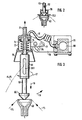
- Fig. 1 shows a double-wire twisting spindle, the upper end of the bobbin case 62, the upper end of the thread inlet tube 63, the opening of which is widened in a funnel shape, and two feed bobbins 64 and 65, which are placed one above the other, of which the threads are overhead, i.e. are pulled upwards and run together into the thread inlet tube 63.
- the two threads F4 and F5 then pass together through the hollow spindle axis before they leave the conventional thread storage disk (not shown) through the radial thread guide channel and run with balloon formation to the sleeve 61 arranged in the region of the apex of the balloon, which in the present case has the function of otherwise usual balloon thread guide exercises.
- the sleeve 61 is provided with a lateral opening 61.1 in the form of a longitudinal slot for the entry of the thread F4, F5.
- the sleeve 61 is rotatable in a in by means of a bearing 50 the extension of the sleeve lying support tube 71 mounted, which in turn is mounted on the machine frame, not shown, adjustable in the axial direction.
- a further bearing 51 is inserted for a bolt 52 coaxial to the spindle axis, which carries at its lower end a conical body 52.1, the shape of which is preferably adapted to the shape of the inlet funnel at the upper end of the thread inlet tube 63.
- a holding magnet 52.2 is preferably inserted in the cone body 52.1, to which counter-magnets 63.1 in the upper end of the thread inlet tube 63 are assigned.
- the bolt 52 serves as a bearing bolt for a twisted wing arrangement.
- a bush 66 is pushed onto the bearing pin 52, on which a carrier 66.1 is attached.
- An angled lever arm 67 is articulated on the carrier 66.1 and has at its free end a lever section 67.1 which projects into the gap between the protective jacket 62 and the upper supply spool 65.
- a roller 68 is attached, which is rotatable about a substantially vertical axis.
- a thread guide roller 69 is also rotatably mounted on the lever section 67.1, via which the thread F4 coming from the lower supply bobbin 64 runs.
- the thread F5 coming from the upper supply spool 65 runs directly to the thread inlet pipe 63 without the aid of a drainage aid.
- the twisted wing arrangement is pivoted further to the center of the spindle axis. It is always ensured that the thread F4 coming from the lower supply spool 64 can be drawn off in a contact-free manner with respect to the upper supply spool 65. This ensures that the thread F4 coming from the lower supply bobbin runs smoothly past the upper supply bobbin 65.
- the conical body 52.1 can be inserted into the upper end of the thread inlet tube 63 by axially lowering the holding tube 71 in order to prevent any further unwanted removal of the thread.
- the sleeve 61 is set in rotation by the twine thread F4, F5, which laterally enters the sleeve.
- the diameter of the slotted sleeve 61 working as a balloon thread guide is preferably selected such that the thread F4, F5 entering the slot 61.1 laterally exerts a sufficiently high torque on the sleeve 61.
- a downwardly open cap 70 is pushed onto the bolt 52 and has an outwardly directed flange ring 70.1, which lies opposite the upper edge of the funnel-shaped thread inlet tube 63.
- This cap 70 forms a run-in aid in the form of a loading weight. Such a run-in aid is used when it is necessary to additionally brake the threads before they enter the thread feed pipe.
- Another special task is to prevent loops in the single thread from entering the thread inlet tube or the spindle vertical axis.
- the braking force exerted by the cap 70 can, if necessary, be changed by applying additional weights, or else by selecting corresponding caps with different weights.
- Any suitable adjustment device can be used for lowering the holding tube 71 and thus the sleeve 61 and the bolt 52 provided with the conical body 52.1 in the direction of the arrow f8, preferably a pneumatic piston-cylinder arrangement, for example in such a way that a holding cylinder 71 in a pressure cylinder 72 guided piston 73 is attached.
- the holding tube 71 or the pressure cylinder 72 provided for adjusting the holding tube 71 is preferably pivotally mounted on the machine frame (arrow f9).
- a tab 76 is attached to the side of the pressure cylinder 72 and is mounted on a holder 78 so that it can pivot about the axis 77.
- the holder 78 is mounted on the machine frame, which is represented by a bar 79 through which a compressed air line 80 is guided.
- a branch line 81 which leads to the pressure cylinder 72, is connected to this compressed air line 80 such that the upper side of the piston 73 against the force of a return spring 74 can be acted upon with compressed air in order to adjust the sliding sleeve 61 together with the bolt 52 downward.
- a protective cap 75 is preferably attached to the underside of the printing cylinder 72.
Landscapes
- Engineering & Computer Science (AREA)
- Mechanical Engineering (AREA)
- Textile Engineering (AREA)
- Spinning Or Twisting Of Yarns (AREA)
- Unwinding Of Filamentary Materials (AREA)
- Filamentary Materials, Packages, And Safety Devices Therefor (AREA)
Applications Claiming Priority (2)
| Application Number | Priority Date | Filing Date | Title |
|---|---|---|---|
| DE4010018 | 1990-03-29 | ||
| DE4010018A DE4010018C2 (de) | 1990-03-29 | 1990-03-29 | Spindel zum Herstellen eines Fadens |
Publications (2)
| Publication Number | Publication Date |
|---|---|
| EP0448950A2 true EP0448950A2 (fr) | 1991-10-02 |
| EP0448950A3 EP0448950A3 (en) | 1991-11-27 |
Family
ID=6403275
Family Applications (1)
| Application Number | Title | Priority Date | Filing Date |
|---|---|---|---|
| EP19910102233 Withdrawn EP0448950A3 (en) | 1990-03-29 | 1991-02-18 | Spindle for producing a yarn |
Country Status (5)
| Country | Link |
|---|---|
| US (1) | US5167112A (fr) |
| EP (1) | EP0448950A3 (fr) |
| JP (1) | JPH0625922A (fr) |
| CZ (1) | CZ279950B6 (fr) |
| DE (1) | DE4010018C2 (fr) |
Families Citing this family (3)
| Publication number | Priority date | Publication date | Assignee | Title |
|---|---|---|---|---|
| DE19727609C1 (de) * | 1997-06-28 | 1999-03-18 | Hamel Ag | Verfahren zum integrierten Fachen und Zwirnen |
| US6167687B1 (en) * | 1998-02-11 | 2001-01-02 | Nextrom Ltd. | Group twinner for single and double conductor bobbins and method of making communication cables |
| KR101291735B1 (ko) * | 2011-08-26 | 2013-07-31 | (주)에나인더스트리 | 권선기용 플라이 장치 |
Family Cites Families (19)
| Publication number | Priority date | Publication date | Assignee | Title |
|---|---|---|---|---|
| US2834179A (en) * | 1953-04-28 | 1958-05-13 | Nishimura Katsuji | Thread twisting machine |
| US2830432A (en) * | 1956-06-26 | 1958-04-15 | Western Electric Co | Strand uncoiling apparatus |
| US2831311A (en) * | 1956-06-26 | 1958-04-22 | Western Electric Co | Uncoiling apparatus |
| CH413677A (de) * | 1963-02-04 | 1966-05-15 | Volkmann & Co | Vorrichtung an Mehrfachdrahtzwirnmaschinen zum Festhalten des von der Vorlagespule ablaufenden Fadens bei Fadenbruch |
| GB1052715A (fr) * | 1964-07-02 | |||
| DE1510854B1 (de) * | 1965-08-06 | 1970-07-09 | Palitex Project Co Gmbh | Mehrfachdrahtzwirn- oder -spinnspindel |
| US3290873A (en) * | 1965-10-21 | 1966-12-13 | Alfred W Vibber | Apparatus for plying strands |
| DE1560257A1 (de) * | 1966-06-06 | 1970-07-23 | Palitex Project Co Gmbh | Doppeldrahtzwirnspindel |
| DE1813801A1 (de) * | 1968-12-10 | 1970-07-02 | Hamel Gmbh Zwirnerei U Spinner | Doppeldrahtzwirnanordnung |
| DE2258183A1 (de) * | 1972-03-27 | 1973-10-04 | Erhard Rinnelt | Verfahren und vorrichtung zum behandeln endloser faeden |
| DE2246174C3 (de) * | 1972-09-20 | 1975-11-20 | Hamel Gmbh Zwirnmaschinen, 4400 Muenster | Rotor einer Doppeldrahtzwirnspindel zur Aufnahme eines frei drehbaren Spulenträgers |
| GB1463453A (fr) * | 1974-04-13 | 1977-02-02 | ||
| US4028870A (en) * | 1974-08-03 | 1977-06-14 | Kabushiki Kaisha Toyoda Jidoshokki Seisakusho | Method and device for preventing creation of fuzzy fibers of yarn during twisting operation of the multiple twister |
| DE2628125C3 (de) * | 1976-06-23 | 1979-03-08 | Palitex Project-Company Gmbh, 4150 Krefeld | Spinn- oder Zwirnmaschine |
| CS197692B1 (en) * | 1977-11-12 | 1980-05-30 | Ferdinand Lenorak | Winding machine with multiple twist spindle |
| DE3118873C2 (de) * | 1981-05-13 | 1985-01-03 | Palitex Project-Company Gmbh, 4150 Krefeld | Doppeldraht-Zwirnspindel |
| DE3130615C2 (de) * | 1981-08-01 | 1983-12-01 | Palitex Project-Company Gmbh, 4150 Krefeld | Fadenführungsvorrichtung |
| IT1222118B (it) * | 1987-07-24 | 1990-08-31 | Savio Spa | Aletta dipanatrice rotante attorno ad un perno sospeso sopra il fuso a doppia torsione per lo svolgimento di rocche sovrapposte |
| JPH0311250Y2 (fr) * | 1987-11-30 | 1991-03-19 |
-
1990
- 1990-03-29 DE DE4010018A patent/DE4010018C2/de not_active Expired - Fee Related
-
1991
- 1991-02-18 EP EP19910102233 patent/EP0448950A3/de not_active Withdrawn
- 1991-03-22 JP JP3059014A patent/JPH0625922A/ja active Pending
- 1991-03-25 US US07/674,562 patent/US5167112A/en not_active Expired - Fee Related
- 1991-03-29 CZ CS91876A patent/CZ279950B6/cs unknown
Also Published As
| Publication number | Publication date |
|---|---|
| DE4010018C2 (de) | 1994-04-14 |
| US5167112A (en) | 1992-12-01 |
| JPH0625922A (ja) | 1994-02-01 |
| DE4010018A1 (de) | 1991-10-02 |
| EP0448950A3 (en) | 1991-11-27 |
| CZ279950B6 (cs) | 1995-09-13 |
| CS9100876A2 (en) | 1991-11-12 |
Similar Documents
| Publication | Publication Date | Title |
|---|---|---|
| DE3400327A1 (de) | Glockenspinnvorrichtung | |
| DE2050490B2 (de) | Mehrstufige fadenbremsvorrichtung an einer doppeldrahtzwirnspindel | |
| EP0448949B1 (fr) | Broche pour produire un fil | |
| CH658870A5 (de) | Doppeldraht-zwirnspindel. | |
| DE2163140B2 (de) | Vorrichtung zum selbsttätigen Anspinnen an Ringspinnmaschinen | |
| DE4408262C2 (de) | Einrichtung zum Einstellen von Kapselfadenbremsen an Zwirnmaschinen, insbesondere Doppeldraht-Zwirnmaschinen | |
| CH657157A5 (de) | Fadenfuehrungsvorrichtung. | |
| EP0448950A2 (fr) | Broche pour produire un fil | |
| DE2939435A1 (de) | Fadenueberwachungseinrichtung | |
| DE3310438C2 (de) | Vorrichtung zur Veränderung des Durchmessers einer Ablaufhilfe für den Überkopfabzug eines auf eine Aufwickelspule aufzuwickelnden Fadens von einer Vorlagespule | |
| DE1160340B (de) | Doppeldrahtzwirnspindel mit Fadenspeicherrinne und im Fadenlauf vor dieser liegenden Fadenbremse | |
| EP0031843B2 (fr) | Flyer pour banc a broches | |
| DE4010019A1 (de) | Spindel zum herstellen eines fadens | |
| DE10151167A1 (de) | Verfahren und Vorrichtung zum Kablieren oder Verzwirnen von mindestens zwei Fäden sowie Kablier- und/oder Doppeldrahtzwirn-Spindel zur Durchführung dieses Verfahrens | |
| EP0383960B1 (fr) | Métier à retordre à double torsion | |
| DE3101146A1 (de) | "spinnaggregat fuer eine umwindegarnspinnmaschine" | |
| DE3741432C2 (fr) | ||
| EP0464424B1 (fr) | Procédé pour réguler automatiquement la force de freinage d'un frein de fil situé dans la broche creuse d'une broche à retordre à double torsion et broche à retordre à double torsion équipée d'un tel frein de fil | |
| DE1510847C3 (de) | Federnd nachgiebige Fadenbremse | |
| DE2713624A1 (de) | Verfahren und vorrichtung zum selbsttaetigen einfaedeln eines fadens in einen spinn- oder zwirnlaeufer | |
| DE10324653B4 (de) | Kabliermaschine und Kablierverfahren | |
| DE19540790C1 (de) | Zwirnspindel, insbesondere für eine mehrere Zwirnspindeln aufweisende Doppeldraht-Zwirnmaschine | |
| DE3840376A1 (de) | Vorrichtung zum ergreifen eines fadens nach einem fadenbruch bei einer doppeldrahtzwirnmaschine | |
| CH399972A (de) | Vorrichtung zur Verringerung der Fadenspannung | |
| DE2234096B1 (de) | Doppeldrahtzwirnmaschine mit handknoter |
Legal Events
| Date | Code | Title | Description |
|---|---|---|---|
| PUAI | Public reference made under article 153(3) epc to a published international application that has entered the european phase |
Free format text: ORIGINAL CODE: 0009012 |
|
| AK | Designated contracting states |
Kind code of ref document: A2 Designated state(s): DE ES FR GB IT |
|
| PUAL | Search report despatched |
Free format text: ORIGINAL CODE: 0009013 |
|
| AK | Designated contracting states |
Kind code of ref document: A3 Designated state(s): DE ES FR GB IT |
|
| 17P | Request for examination filed |
Effective date: 19920520 |
|
| 17Q | First examination report despatched |
Effective date: 19931014 |
|
| STAA | Information on the status of an ep patent application or granted ep patent |
Free format text: STATUS: THE APPLICATION HAS BEEN WITHDRAWN |
|
| 18W | Application withdrawn |
Withdrawal date: 19951021 |