EP0444790A2 - Zykloidisches Planetenuntersetzungsgetriebe - Google Patents
Zykloidisches Planetenuntersetzungsgetriebe Download PDFInfo
- Publication number
- EP0444790A2 EP0444790A2 EP91301059A EP91301059A EP0444790A2 EP 0444790 A2 EP0444790 A2 EP 0444790A2 EP 91301059 A EP91301059 A EP 91301059A EP 91301059 A EP91301059 A EP 91301059A EP 0444790 A2 EP0444790 A2 EP 0444790A2
- Authority
- EP
- European Patent Office
- Prior art keywords
- external gear
- gear
- eccentric member
- flange
- pins
- Prior art date
- Legal status (The legal status is an assumption and is not a legal conclusion. Google has not performed a legal analysis and makes no representation as to the accuracy of the status listed.)
- Granted
Links
- 239000003638 chemical reducing agent Substances 0.000 title abstract description 30
- 239000000463 material Substances 0.000 claims abstract description 35
- 230000037431 insertion Effects 0.000 claims 8
- 238000003780 insertion Methods 0.000 claims 8
- 230000005540 biological transmission Effects 0.000 abstract description 8
- 230000033001 locomotion Effects 0.000 abstract description 5
- 238000010276 construction Methods 0.000 abstract description 4
- 230000007246 mechanism Effects 0.000 description 10
- 238000003754 machining Methods 0.000 description 4
- 238000000034 method Methods 0.000 description 4
- 238000004519 manufacturing process Methods 0.000 description 3
- 230000015572 biosynthetic process Effects 0.000 description 2
- 101100520142 Caenorhabditis elegans pin-2 gene Proteins 0.000 description 1
- 230000008602 contraction Effects 0.000 description 1
- 230000003247 decreasing effect Effects 0.000 description 1
- 230000000694 effects Effects 0.000 description 1
- 230000002349 favourable effect Effects 0.000 description 1
- 238000001746 injection moulding Methods 0.000 description 1
- 238000000465 moulding Methods 0.000 description 1
- 238000010137 moulding (plastic) Methods 0.000 description 1
Images


Classifications
-
- F—MECHANICAL ENGINEERING; LIGHTING; HEATING; WEAPONS; BLASTING
- F16—ENGINEERING ELEMENTS AND UNITS; GENERAL MEASURES FOR PRODUCING AND MAINTAINING EFFECTIVE FUNCTIONING OF MACHINES OR INSTALLATIONS; THERMAL INSULATION IN GENERAL
- F16H—GEARING
- F16H15/00—Gearings for conveying rotary motion with variable gear ratio, or for reversing rotary motion, by friction between rotary members
-
- F—MECHANICAL ENGINEERING; LIGHTING; HEATING; WEAPONS; BLASTING
- F16—ENGINEERING ELEMENTS AND UNITS; GENERAL MEASURES FOR PRODUCING AND MAINTAINING EFFECTIVE FUNCTIONING OF MACHINES OR INSTALLATIONS; THERMAL INSULATION IN GENERAL
- F16H—GEARING
- F16H1/00—Toothed gearings for conveying rotary motion
- F16H1/28—Toothed gearings for conveying rotary motion with gears having orbital motion
- F16H1/32—Toothed gearings for conveying rotary motion with gears having orbital motion in which the central axis of the gearing lies inside the periphery of an orbital gear
Definitions
- the present invention relates to an improvement of an internal meshing type planetary gear speed changing device in which an internal gear has teeth of circular arc profile, and an external gear has teeth of trochoidal profile inclusive of an epitrochoidal parallel curve, circular arc tooth profile or the like, so that rotation of an eccentric member fitted in the external gear causes the external gear to swingingly rotate, and that rotation thus input is output after being reduced in speed (or increased in speed) through the external and internal gears which are intermeshed with each other. More particularly, the invention relates to a structure of the internal meshing type planetary gear speed changing device which is made of plastic material such that it can be reduced in size and weight, and that it can be decreased in number of component parts, have a compact construction, and be produced at a low cost with high productivity.
- Cyclo Speed Reducer each component part of which is made of a plastic material for the purpose of further reducing the Cyclo Speed Reducer described above (hereinafter referred to as the internal meshing type planetary gear reducer) in size and weight and also in number of component parts.
- the internal meshing type planetary gear reducer See Japanese Utility Model Unexamined Publication No. 63-30648.
- This internal meshing type planetary gear reducer is made of plastic material which has not only flexibility but also a favorable sliding characteristic so that rotations are effected relatively smoothly and smooth transmission of torque is conducted in the reducer. Therefore, the internal meshing type planetary gear reducer made of plastic material is remarkably useful as a speed reducing rotational member in a domestic electric appliance, an office equipment, an automatic vending machine or the like.
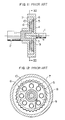
- Fig. 11 is a cross-sectional view of the conventional example of internal meshing type planetary gear reducer
- Fig. 12 is a cross-sectional view of the same as Fig. 11, taken along the line XII-XII of Fig. 11.
- rotation of an input shaft 1 is transmitted to an output shaft 2 in a state of being reduced in speed.
- the example may be, however, arranged in such a manner that the rotation reduced in speed is extracted from an internal gear 7, while the output shaft 2 being fixed.
- An eccentric member 3 is integrally formed with the input shaft 1 made of a plastic material.
- An external gear 4 of a plastic material is fitted on the eccentric member 3.
- the external gear 4 is integrally provided with external teeth 5 of trochoidal profile on an outer periphery thereof.
- Inner pins 6 are integrally formed on the external gear 4.
- the inner pins 6 are formed to project from a side face of the external gear 4 in the direction substantially parallel to a longitudinal axis of the output shaft.
- the internal gear 7 of a plastic material also serves as a lateral wall casing on this side. Besides, this internal gear 7 is stationary in this example.
- the internal gear 7 is integrally formed with circular arc teeth 8 to mesh with the external teeth 5 of the external gear 4.
- the plastic output shaft 2 is integrally provided at the one end portion with a disk-like flange 9.
- This flange 9 includes inner-pin holes 10 into which the above-mentioned inner pins 6 are inserted.
- the input shaft 1 is rotatably supported in a bearing hole 11 provided at the one end portion of the output shaft 2.
- the rotation of the input shaft 1 appears as swinging rotation of the external gear 4 via the eccentric member 3. Then, the swinging rotation of the external gear 4 is turned into rotation of the flange 9 reduced in speed through the inner pins 6, and the output force with low speed rotation of the flange 9 is transmitted to the output shaft 2.
- the known internal meshing type planetary gear reducer made of plastic material as described has technical problems as follows.
- Fig. 13 is a cross-sectional view showing a condition of contacts between the inner pins 6 and the inner-pin holes 10 at a moment of the operation.
- a center O1 of the external gear 4 provided with the inner pins 6 is eccentrically disposed by a distance e , apart from a rotational center O2 of the flange 9 (which is disposed at the same position as a rotational center of the output shaft 2) including the inner-pin holes 10.
- the center O1 is just below the rotational center O2 at the distance e .
- the inner pin 6 at every location is in contact with the bottom of the associated inner-pin hole 10, as viewed in the figure.
- a torque is transmitted when the inner pins 6 contact with the inner-pin holes 10.
- the torque transmission is mainly effected through the inner pins 6 and the inner-pin holes 10 located at positions X, Y, and Z because the inner pins 6 are swingingly rotated in a direction indicated by an arrow P in the figure. Contacts at the residual positions do not contribute to the torque transmission, and the resistive force interferes with the speed change function.
- the conventional internal meshing type planetary gear reducer is so designed that the inner pins 6 at all the locations will be brought into contact with the respective inner-pin holes 10.
- An object of the present invention is to provide an internal meshing type planetary gear speed changing device made of plastic material having a gear mechanism in which contacts between inner pins and inner pin-holes are smooth and do not interfere with transmission of a torque, with backlashes of the gear mechanism being kept small.
- the present invention has a structure mainly characterized in that only the inner pins which serve to transmit a torque are brought into contact with inner-pin holes at a predetermined range of contacting location so as to prevent unnecessary contacts between inner pins and inner-pin holes at other locations where no torque is transmitted.
- Fig. 1 is a cross-sectional view of a planetary gear speed changing device showing one preferred embodiment of the invention.
- Fig. 2 is a cross-sectional view of the same as Fig. 1, taken along the line II-II of Fig. 1.
- rotation of an input shaft 21 is transmitted to an output shaft 22 in a state of being reduced in speed.
- the embodiment may be, however, arranged in such a manner that the output shaft 22 is fixed while the rotation reduced in speed is extracted from an internal gear 27, or that rotation input from the output shaft 22 is increased in speed prior to being transmitted to the input shaft 21.
- a disk-like eccentric member 23 is formed integrally with the input shaft 21 made of a plastic material.
- An external gear 24 of a plastic material is shaped like a disk and fitted on the eccentric member 23.
- the external gear 24 is integrally provided with external gear teeth 25 of trochoidal profile on an outer periphery thereof.
- a plurality of inner pins 26 are formed on the external gear 24 integrally therewith, the inner pins 26 being formed to project from a side face of the external gear 24 in the direction substantially parallel to a longitudinal axis of the output shaft.
- An internal gear 27 of a plastic material is formed into a ring-like configuration, separately from a casing 29.
- the internal gear 27 is integrally provided with teeth 28 of circular arc profile which internally mesh with the external teeth 25 of the external gear 24.
- the internal gear 27 is received within both of the casing 29 located on one side of the internal gear and a casing 30 located on the other side thereof.
- the casing 29 of a plastic material located on one side comprises an annular side wall portion 29A, a cylindrical portion 29B integrally formed on an outer periphery of the side wall portion 29A, and a cylindrical bearing portion 29C integrally formed on an inner periphery of the side wall portion 29A.
- the outer casing 30 is fitted on an outer periphery of the internal gear 27.
- the internal gear 27 is provided with a projection 27A at a certain location corresponding to a recess portion 30A which is formed in the outer casing 30 so as to be fitted on the projection 27A, thereby preventing the internal gear 27 from rotation.
- the outer casing 30 comprises an annular side wall portion 30B and a cylindrical portion 30C integrally formed on an outer periphery of the side wall portion 30B.
- the side wall portion 30B supports the input shaft 21 extending therethrough.
- the plastic output shaft 22 is integrally provided at the one end portion with a disk-like flange 31.
- the flange 31 includes inner-pin holes 32 into which the inner pins 26 are inserted.
- the one end of the input shaft 21 is received in a bearing bore 33 provided at the one end portion of the output shaft 22, so that the one end of the input shaft 21 is rotatably supported by means of the output shaft 22.
- the inner pins 26 have such constructions as to be described below.
- a center O3 of the external gear 24 provided with the inner pins 26 is eccentrically disposed, by a distance e apart from a rotational center O4 of the flange 31 (which is disposed at the same position as a rotational center of the output shaft 22) including the inner-pin holes 32.
- the center O3 is just below the center O4 at the distance of e .
- Each inner pin 26 is provided with cutouts 26A on the inner and outer sides thereof with respect to the center O3 of the external gear 24 so that a cross section of the inner pin2 6 is substantially elliptic. Since the inner pins 26 are swingingly rotated in a direction indicated by an arrow P1 in Fig.
- a torque is thus transmitted from the inner pins 26 to the inner-pin holes 32 mainly through the inner pins 26 located at positions of X1, Y1, and Z1.
- the inner pins 26 at the residual positions are unnecessary to be in contact with the inner-pin holes 32. More specifically, the inner pins 26 are not in contact with the inner-pin holes 32 at the positions of P and Q, due to provision of the cutouts 26A, as shown in Fig. 3.
- the inner pins 26 are so arranged as to be apart from the inner peripheries of the inner-pin holes 32 with slight gaps H therebetween at the positions of R, S, and T.
- the rotation of the input shaft 21 appears as swinging rotation of the external gear 24 via the eccentric member 23.
- the torque of the swinging rotation of the external gear 24 is transmitted to the inner-pin holes 32 of the flange 31 only by the inner pins 26 located at the positions of X1, Y1, and Z1 at a moment shown in Fig. 3, causing the rotation of the flange 31 to be reduced in speed.
- the output force with low speed rotation of the flange 31 is transmitted to the output shaft 22.
- the inner pins 26 are provided with the cutouts 26A on both inner and outer sides thereof, the inner and outer sides being extended opposite to each other and facing in the radial direction of the external gear 24.
- the invention is, however, not restricted to the above embodiment.
- Fig. 4 illustrates another example of the cutout in accordance with the invention, in which each inner pin 26 is cut away to form the cutouts 26B on inner and outer sides thereof, the inner and outer sides being extended opposite to each other and facing in a radial direction of the external gear 24, substantially along the outer periphery of the pin 26.
- each inner-pin hole 32 may be arranged in such a manner that the inner periphery of the hole is formed with cutouts 32A, the cutouts 32A being located on the inner and outer sides thereof which are extended opposite and facing to each other in a radial direction of the flange 31.
- the cutouts may be formed on either the inner pins 26 or the inner-pin holes 32.
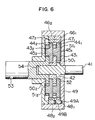
- Fig. 6 shows in cross section a second embodiment of a multistage planetary gear reducer of the internal meshing type, according to the invention.
- An input shaft 41 made of a plastic material is integrally formed with a disk-like eccentric member 42.
- a first external gear 431 of a plastic material is shaped like a disk and fitted on the eccentric member 42.
- External teeth 441 of trochoidal profile are provided on an outer periphery of the first external gear 431 formed integrally therewith.
- the first external gear 431 includes a plurality of integrally-formed inner pins 451.
- the inner pins 451 are formed so as to project from a lateral surface of the first external gear 431 in the direction substantially parallel to a longitudinal axis of the input shaft.
- a first internal gear 461 made of a plastic material is in a ring-like configuration.
- Gear teeth 471 of circular arc profile which internally mesh with the external teeth 441 of the first external gear 431 are provided on an inner periphery of the first internal gear 461 formed integrally therewith.
- the plastic first internal gear 461 is provided with a projection 481 at a certain location corresponding to a recess portion 49A which is formed in an outer casing 49 of a plastic material so as to be fitted on the projection 481, thereby preventing the first internal gear 461 from rotational movement.
- the input shaft 41 rotatably supports a first-flange 501, of a plastic material which is formed with inner-pin holes 511 and integrally provided with an eccentric member 52.
- the inner pins 451 are inserted in the inner-pin holes 511 formed in the first flange 501.
- the input shaft 41 is provided extending through the first flange 501 and the eccentric member 52.
- the eccentric member 52 is fitted in a second external gear 432 made of a plastic material.
- the second external gear 432 is provided with a plurality of inner pins 452 formed integrally therewith.
- the inner pins 452 are formed to project from a lateral face of the second external gear 432 in the direction substantially parallel to the longitudinal axis of the input shaft 41.
- a second internal gear 462 made of a plastic material is in a ring-like configuration.
- Teeth 472 of circular arc profile which internally mesh with external teeth 442 of the second external gear 432 are formed on an inner periphery of the second internal gear 462 integrally therewith.
- the second internal gear 462 is provided with a projection 482 at a certain location corresponding to a recess portion 49B which is formed in a lateral surface of the first internal gear 461 so as to be fitted on the projection 482, thereby preventing the second internal gear 462 from rotational movement.
- a disk-like second flange 502 is integrally formed at one end portion of an output shaft 53 made of a plastic material.
- the second flange 502 is provided with inner-pin holes 512 where the inner pins 452 of the second external gear 432 are inserted.
- the end portion of the input shaft 41 is inserted into a bearing bore 54 formed at the end portion of the output shaft 53 so as to be supported rotatably by the output shaft 53.
- the multistage planetary gear reducer of the internal meshing type constructed in the above-mentioned manner which is the second embodiment of the invention will operate as follows.
- Rotation of the input shaft 41 appears in a form of swinging rotation of the first external gear 431 through the eccentric member 42. Then, a torque of the swinging rotation of the first external gear 431 is transmitted to the inner-pin holes 511 of the first flange 501 via the inner pins 451, causing the rotation of the flange 501 to be reduced in speed.
- the speed-reduced rotation of the first flange 501 swingingly rotates the second external gear 432 through the eccentric member 52.
- a torque of the swinging rotation of the second external gear 432 is transmitted to the inner-pin holes 512 of the second flange 502 via the inner pins 452, thereby enabling the rotation of the second flange 502 to be reduced in speed.
- the rotation of the second flange 502 is transmitted to the output shaft 53 in a state of low speed rotation of the output shaft 53.
- the shapes and constructions of the inner pins and the inner-pin holes are substantially the same as those of the planetary gear reducer shown in Figs. 1 to 5.
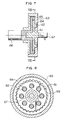
- Figs. 7 and 8 illustrate a third embodiment of the invention, in which inner pins 62 of an external gear 61 are received in inner-pin holes 64 formed on an outer casing 63.
- An internal gear 65 which meshes with the external gear 61 is integrally formed on an outer periphery of a flange which is provided at one end portion of an output shaft 66.
- rotation of the input shaft 67 appears in a state of swinging rotation of the internal gear 65 reduced in speed, and the output shaft 66 rotates at the reduced speed together with the internal gear 65.
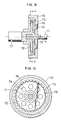
- an internal gear 73 including an annular portion and a cylindrical portion is fitted on an eccentric member 72 integrally formed with an input shaft 71 so as to be swingingly rotated.
- the internal gear 73 is integrally provided with inner pins 74 which are inserted in inner-pin holes 76 formed in an outer casing 75.
- An external gear 78 integrally formed at one end portion of an output shaft 77 internally mesh with the internal gear 73.
- rotation of the input shaft 71 appears in a state of swinging rotation of the internal gear 73 reduced in speed through the eccentric member 72.
- the swinging rotation of the internal gear 73 leads to speed-reduced rotation of the external gear 78 which is transmitted to the output shaft 77.
- the corresponding relation between the respective inner pins and the inner-pin holes is predetermined as shown in Figs. 1 to 5.
- the interconnecting arrangements of the inner pins and inner-pin holes are almost similar to those in the embodiment shown in Figs. 1 to 5.
- the internal meshing type planetary gear reducer according to the invention also operates as a speed increaser if the input and output shafts are interchanged with each other to be reversely operated, and therefore the application of the invention is not restricted to the speed reducer.
Landscapes
- Engineering & Computer Science (AREA)
- General Engineering & Computer Science (AREA)
- Mechanical Engineering (AREA)
- Retarders (AREA)
- Gear Transmission (AREA)
Applications Claiming Priority (2)
| Application Number | Priority Date | Filing Date | Title |
|---|---|---|---|
| JP2038360A JP2739071B2 (ja) | 1990-02-21 | 1990-02-21 | 内接噛合型遊星歯車増減速機 |
| JP38360/90 | 1990-02-21 |
Publications (3)
| Publication Number | Publication Date |
|---|---|
| EP0444790A2 true EP0444790A2 (de) | 1991-09-04 |
| EP0444790A3 EP0444790A3 (en) | 1992-04-08 |
| EP0444790B1 EP0444790B1 (de) | 1995-06-28 |
Family
ID=12523116
Family Applications (1)
| Application Number | Title | Priority Date | Filing Date |
|---|---|---|---|
| EP91301059A Expired - Lifetime EP0444790B1 (de) | 1990-02-21 | 1991-02-11 | Zykloidisches Planetenuntersetzungsgetriebe |
Country Status (7)
| Country | Link |
|---|---|
| US (1) | US5123883A (de) |
| EP (1) | EP0444790B1 (de) |
| JP (1) | JP2739071B2 (de) |
| KR (1) | KR0153243B1 (de) |
| AT (1) | ATE124515T1 (de) |
| CA (1) | CA2036340C (de) |
| DE (1) | DE69110704D1 (de) |
Cited By (23)
| Publication number | Priority date | Publication date | Assignee | Title |
|---|---|---|---|---|
| EP0593036A1 (de) * | 1992-10-15 | 1994-04-20 | Sumitomo Heavy Industries, Ltd. | Untersetzungsgetriebe für hin und her gehende Drehbewegung |
| FR2703746A1 (fr) * | 1993-04-05 | 1994-10-14 | Sumitomo Heavy Industries | Train d'engrenage réducteur ou multiplicateur utilisant une structure d'engrenage planétaire à denture intérieure. |
| FR2712366A1 (fr) * | 1993-11-10 | 1995-05-19 | Sumitomo Heavy Industries | Train réducteur à engrenages, en particulier pour équipement de bureau, comprenant un mécanisme réducteur à engrenages du type planétaire et à engrènement intérieur. |
| FR2717239A1 (fr) * | 1994-03-08 | 1995-09-15 | Sumitomo Heavy Industries | Dispositif de train d'engrenage à denture intérieure. |
| DE19736503A1 (de) * | 1997-08-22 | 1999-02-25 | Schaeffler Waelzlager Ohg | Vorrichtung zur Umwandlung einer Rotativbewegung in eine Linearbewegung |
| WO1999019966A1 (en) * | 1997-10-09 | 1999-04-22 | Ut Automotive Dearborn, Inc. | Multi-functional apparatus employing an intermittent motion mechanism |
| US5910065A (en) * | 1996-07-26 | 1999-06-08 | Agco Limited | Transmission with creep gear |
| WO2003044390A1 (en) * | 2001-10-16 | 2003-05-30 | Pro Quip International Korea Co., Ltd. | Decelerator for automobile actuator |
| WO2006034921A1 (de) * | 2004-09-30 | 2006-04-06 | Robert Bosch Gmbh | Exzentergetriebe mit zykloiden-triebstock-verzahnung |
| EP1666765A1 (de) * | 2004-12-03 | 2006-06-07 | Spinea s.r.o. | Getriebe |
| EP1835197A1 (de) * | 2006-03-13 | 2007-09-19 | Nissin Kogyo Co., Ltd. | Scheibenbremse für ein Fahrzeug |
| WO2009115817A3 (en) * | 2008-03-20 | 2009-11-26 | Ap Driveline Technologies Limited | Wheel winch |
| US7641579B2 (en) | 2007-04-19 | 2010-01-05 | Junkers John K | Eccentric gear mechanism and method of transfering turning force thereby |
| WO2012139674A1 (de) * | 2011-01-15 | 2012-10-18 | Lothar Ginzel | Getriebe |
| EP2677197A4 (de) * | 2011-02-14 | 2014-09-03 | Toshiaki Shimada | Getriebevorrichtung und antriebsvorrichtung |
| CN104633013A (zh) * | 2015-02-06 | 2015-05-20 | 江苏泰来减速机有限公司 | 一种新型机器人用高精度减速器 |
| US20160121474A1 (en) * | 2014-10-31 | 2016-05-05 | Robert Bosch Gmbh | Handheld Machine-Tool Device |
| CN105570391A (zh) * | 2016-03-07 | 2016-05-11 | 东莞市富宝机电科技有限公司 | 一种共轭减速传动机构 |
| CN108869641A (zh) * | 2017-05-12 | 2018-11-23 | 昆山光腾智能机械有限公司 | 针齿摆线减速器及工业机器人 |
| WO2020000303A1 (en) * | 2018-06-28 | 2020-01-02 | Abb Schweiz Ag | Planetary gearbox and associated robot joint and robot |
| EP3657039A1 (de) * | 2018-11-21 | 2020-05-27 | Toyota Jidosha Kabushiki Kaisha | Bremszylinder |
| US20230097445A1 (en) * | 2021-09-28 | 2023-03-30 | Mintrobot Co.,Ltd. | Reducer |
| EP4353417A1 (de) | 2022-10-11 | 2024-04-17 | Hilti Aktiengesellschaft | Mobile werkzeugmaschine mit zuschaltbarer oder permanenter hemmstufe |
Families Citing this family (29)
| Publication number | Priority date | Publication date | Assignee | Title |
|---|---|---|---|---|
| JPH07332441A (ja) * | 1994-06-01 | 1995-12-22 | Fanuc Ltd | 遊星歯車形減速装置 |
| JP3710010B2 (ja) * | 1995-10-19 | 2005-10-26 | 株式会社デンソー | 車両用始動兼補機装置及び車両用始動装置 |
| US5820504A (en) * | 1996-05-09 | 1998-10-13 | Hawk Corporation | Trochoidal tooth gear assemblies for in-line mechanical power transmission, gear reduction and differential drive |
| US6382038B2 (en) | 1997-09-04 | 2002-05-07 | Mcgill University | Transmission device |
| AU8969398A (en) | 1997-09-04 | 1999-03-22 | Mcgill University | Transmission device |
| WO1999023398A2 (en) | 1997-11-03 | 1999-05-14 | Ker-Train Holdings Ltd. | Planetary transmission |
| JP3292131B2 (ja) * | 1998-03-09 | 2002-06-17 | 松下電器産業株式会社 | 駆動伝達装置 |
| DE19910922A1 (de) * | 1999-03-12 | 2000-09-14 | Bosch Gmbh Robert | Exzenterzahnradgetriebe |
| TWI223034B (en) * | 2002-08-30 | 2004-11-01 | Sumitomo Heavy Industries | Power transmission device |
| US6745812B1 (en) * | 2003-02-24 | 2004-06-08 | Tai-Ping Liu | Hypocycloid drive device for adjusting slat angles for a venetian blind |
| US6739373B1 (en) * | 2003-03-10 | 2004-05-25 | Tai-Ping Liu | Lift control device for a roller shade |
| JP2004286044A (ja) * | 2003-03-19 | 2004-10-14 | Sumitomo Heavy Ind Ltd | 内歯揺動型内接噛合遊星歯車装置 |
| JP2006015856A (ja) * | 2004-07-01 | 2006-01-19 | Toyoda Mach Works Ltd | 伝達比可変操舵装置 |
| JP2007211905A (ja) * | 2006-02-09 | 2007-08-23 | Seiko Precision Inc | 減速機 |
| CN100360829C (zh) * | 2006-04-30 | 2008-01-09 | 重庆大学 | 二次包络摆线行星传动装置 |
| US20080148889A1 (en) * | 2006-12-22 | 2008-06-26 | Andrew James Elliot | Actuator |
| KR20130038432A (ko) * | 2011-10-10 | 2013-04-18 | 주식회사 만도 | 전자식 디스크 브레이크 |
| DE102012021414B4 (de) * | 2011-11-02 | 2017-07-06 | Mando Corporation | Elektromechanische Bremse |
| CN103644255A (zh) * | 2013-11-13 | 2014-03-19 | 安徽费洛卡重工传动有限公司 | 一种单级行星齿轮减速机 |
| JP6463212B2 (ja) * | 2015-04-30 | 2019-01-30 | 国立大学法人東京工業大学 | 遊星ローラ駆動型内接式遊星歯車減速装置 |
| JP6825326B2 (ja) * | 2016-11-18 | 2021-02-03 | 株式会社ジェイテクト | 遊星ローラ式変速装置 |
| JP6898876B2 (ja) * | 2018-02-28 | 2021-07-07 | 住友重機械工業株式会社 | 偏心揺動型減速装置 |
| JP7365766B2 (ja) * | 2018-11-16 | 2023-10-20 | 住友重機械工業株式会社 | 偏心揺動型減速装置 |
| EP3894724A4 (de) * | 2018-12-10 | 2022-07-20 | ABB Schweiz AG | Gehäuse für kunststoffgetriebe und zugehöriges kunststoffgetriebe und roboter |
| JP7463265B2 (ja) * | 2020-07-29 | 2024-04-08 | 美的集団股▲フン▼有限公司 | 内接噛合遊星歯車装置及びアクチュエータ |
| US12025093B2 (en) * | 2020-10-06 | 2024-07-02 | Vestas Wind Systems A/S | Wind turbine power transmission system |
| DE102020213365A1 (de) * | 2020-10-22 | 2022-04-28 | Robert Bosch Gesellschaft mit beschränkter Haftung | Exzentergetriebe für einen Bremskrafterzeuger, Bremskrafterzeuger |
| CN115750741A (zh) * | 2022-11-30 | 2023-03-07 | 重庆天作传动科技有限公司 | 矢量凸轮减速机 |
| CN118274680B (zh) * | 2024-05-31 | 2024-07-30 | 泸州豪能传动技术有限公司 | 一种差速器行星齿轮球面多点位检测装置及方法 |
Family Cites Families (15)
| Publication number | Priority date | Publication date | Assignee | Title |
|---|---|---|---|---|
| US3013447A (en) * | 1960-02-23 | 1961-12-19 | Fichtel & Sachs Ag | Eccentric drive transmission mechanism |
| US3307434A (en) * | 1964-06-22 | 1967-03-07 | David G Kope | Speed reducing mechanism |
| IE51023B1 (en) * | 1980-04-02 | 1986-09-03 | Precision Mechanical Dev | Motion transmitting devices having a toothed wheel and independently movable meshing elements |
| JPS59113340A (ja) * | 1982-12-21 | 1984-06-30 | Sumitomo Heavy Ind Ltd | 遊星歯車装置 |
| JPH0683223B2 (ja) * | 1986-02-28 | 1994-10-19 | オムロン株式会社 | プログラマブル・コントロ−ラのリンクユニツト |
| JPS6330648A (ja) * | 1986-07-24 | 1988-02-09 | Masatoshi Asano | 回転体における自己制動方法及び装置 |
| DE3628633A1 (de) * | 1986-08-22 | 1988-03-03 | Kloeckner Humboldt Deutz Ag | Schneidewerk fuer grossballenpressen |
| JPH0771132B2 (ja) * | 1986-11-19 | 1995-07-31 | 日通工株式会社 | 電話機 |
| JPS63259248A (ja) * | 1987-04-15 | 1988-10-26 | Tsuoisu Kk | トルクリミツタ付減速装置 |
| JPS63285350A (ja) * | 1987-05-15 | 1988-11-22 | Tsuoisu Kk | 減速装置 |
| JPH0256943A (ja) * | 1988-04-12 | 1990-02-26 | Sharp Corp | 回路基板への電子回路素子の接続方法、接続構造およびそれを用いる表示装置の製造方法 |
| JPH0643730B2 (ja) * | 1988-08-05 | 1994-06-08 | 大同鋼板株式会社 | 屋根の構造 |
| JPH0663308B2 (ja) * | 1988-08-08 | 1994-08-22 | 元旦ビューティ工業株式会社 | 横葺き屋根構造 |
| JPH0760841B2 (ja) * | 1988-08-22 | 1995-06-28 | 松下電器産業株式会社 | 電子部品実装装置 |
| JPH0265740A (ja) * | 1988-08-31 | 1990-03-06 | Asahi Chem Ind Co Ltd | 着火加熱装置及びその着火加熱装置を装着してなる発煙装置 |
-
1990
- 1990-02-21 JP JP2038360A patent/JP2739071B2/ja not_active Expired - Fee Related
-
1991
- 1991-02-11 DE DE69110704T patent/DE69110704D1/de not_active Expired - Lifetime
- 1991-02-11 EP EP91301059A patent/EP0444790B1/de not_active Expired - Lifetime
- 1991-02-11 AT AT91301059T patent/ATE124515T1/de not_active IP Right Cessation
- 1991-02-12 US US07/654,128 patent/US5123883A/en not_active Expired - Lifetime
- 1991-02-14 CA CA002036340A patent/CA2036340C/en not_active Expired - Fee Related
- 1991-02-19 KR KR1019910002634A patent/KR0153243B1/ko not_active Expired - Fee Related
Cited By (36)
| Publication number | Priority date | Publication date | Assignee | Title |
|---|---|---|---|---|
| EP0593036A1 (de) * | 1992-10-15 | 1994-04-20 | Sumitomo Heavy Industries, Ltd. | Untersetzungsgetriebe für hin und her gehende Drehbewegung |
| US5484345A (en) * | 1992-10-15 | 1996-01-16 | Sumitomo Heavy Industries, Ltd. | Compact gear reducer for rotation through an angle in either directions |
| FR2703746A1 (fr) * | 1993-04-05 | 1994-10-14 | Sumitomo Heavy Industries | Train d'engrenage réducteur ou multiplicateur utilisant une structure d'engrenage planétaire à denture intérieure. |
| US5533942A (en) * | 1993-04-05 | 1996-07-09 | Sumitomo Heavy Industries Ltd. | Speed change gears adopting internal-meshing planetary gear construction |
| FR2712366A1 (fr) * | 1993-11-10 | 1995-05-19 | Sumitomo Heavy Industries | Train réducteur à engrenages, en particulier pour équipement de bureau, comprenant un mécanisme réducteur à engrenages du type planétaire et à engrènement intérieur. |
| FR2717239A1 (fr) * | 1994-03-08 | 1995-09-15 | Sumitomo Heavy Industries | Dispositif de train d'engrenage à denture intérieure. |
| US6018223A (en) * | 1995-04-28 | 2000-01-25 | Lear Automotive Dearborn, Inc. | Multi-functional apparatus employing an intermittent motion mechanism |
| US5910065A (en) * | 1996-07-26 | 1999-06-08 | Agco Limited | Transmission with creep gear |
| WO1999010662A1 (de) * | 1997-08-22 | 1999-03-04 | INA Wälzlager Schaeffler oHG | Vorrichtung zur umwandlung einer rotativbewegung in eine linearbewegung |
| DE19736503A1 (de) * | 1997-08-22 | 1999-02-25 | Schaeffler Waelzlager Ohg | Vorrichtung zur Umwandlung einer Rotativbewegung in eine Linearbewegung |
| WO1999019966A1 (en) * | 1997-10-09 | 1999-04-22 | Ut Automotive Dearborn, Inc. | Multi-functional apparatus employing an intermittent motion mechanism |
| WO2003044390A1 (en) * | 2001-10-16 | 2003-05-30 | Pro Quip International Korea Co., Ltd. | Decelerator for automobile actuator |
| WO2006034921A1 (de) * | 2004-09-30 | 2006-04-06 | Robert Bosch Gmbh | Exzentergetriebe mit zykloiden-triebstock-verzahnung |
| EP1666765A1 (de) * | 2004-12-03 | 2006-06-07 | Spinea s.r.o. | Getriebe |
| WO2006058743A1 (de) * | 2004-12-03 | 2006-06-08 | Spinea S.R.O. | Getriebe |
| US7779971B2 (en) | 2006-03-13 | 2010-08-24 | Nissin Kogyo Co., Ltd. | Vehicular disk brake |
| EP1835197A1 (de) * | 2006-03-13 | 2007-09-19 | Nissin Kogyo Co., Ltd. | Scheibenbremse für ein Fahrzeug |
| US7641579B2 (en) | 2007-04-19 | 2010-01-05 | Junkers John K | Eccentric gear mechanism and method of transfering turning force thereby |
| DE102007061322B4 (de) * | 2007-04-19 | 2016-06-23 | John K. Junkers | Exzentergetriebe und Verfahren zum Übertragen einer Drehkraft durch das Exzentergetriebe |
| WO2009115817A3 (en) * | 2008-03-20 | 2009-11-26 | Ap Driveline Technologies Limited | Wheel winch |
| WO2012139674A1 (de) * | 2011-01-15 | 2012-10-18 | Lothar Ginzel | Getriebe |
| US8936525B2 (en) | 2011-02-14 | 2015-01-20 | Toshiaki Shimada | Gear system and driver |
| JP5784050B2 (ja) * | 2011-02-14 | 2015-09-24 | 利晃 島田 | 歯車装置及び駆動装置 |
| EP2677197A4 (de) * | 2011-02-14 | 2014-09-03 | Toshiaki Shimada | Getriebevorrichtung und antriebsvorrichtung |
| US20160121474A1 (en) * | 2014-10-31 | 2016-05-05 | Robert Bosch Gmbh | Handheld Machine-Tool Device |
| CN104633013A (zh) * | 2015-02-06 | 2015-05-20 | 江苏泰来减速机有限公司 | 一种新型机器人用高精度减速器 |
| CN105570391A (zh) * | 2016-03-07 | 2016-05-11 | 东莞市富宝机电科技有限公司 | 一种共轭减速传动机构 |
| CN108869641B (zh) * | 2017-05-12 | 2021-07-23 | 昆山光腾智能机械有限公司 | 针齿摆线减速器及工业机器人 |
| CN108869641A (zh) * | 2017-05-12 | 2018-11-23 | 昆山光腾智能机械有限公司 | 针齿摆线减速器及工业机器人 |
| WO2020000303A1 (en) * | 2018-06-28 | 2020-01-02 | Abb Schweiz Ag | Planetary gearbox and associated robot joint and robot |
| US11168764B2 (en) | 2018-06-28 | 2021-11-09 | Abb Schweiz Ag | Planetary gearbox and associated robot joint and robot |
| EP3657039A1 (de) * | 2018-11-21 | 2020-05-27 | Toyota Jidosha Kabushiki Kaisha | Bremszylinder |
| US11332113B2 (en) | 2018-11-21 | 2022-05-17 | Toyota Jidosha Kabushiki Kaisha | Brake actuator |
| US20230097445A1 (en) * | 2021-09-28 | 2023-03-30 | Mintrobot Co.,Ltd. | Reducer |
| US11815162B2 (en) * | 2021-09-28 | 2023-11-14 | Mintrobot Co., Ltd. | Reducer |
| EP4353417A1 (de) | 2022-10-11 | 2024-04-17 | Hilti Aktiengesellschaft | Mobile werkzeugmaschine mit zuschaltbarer oder permanenter hemmstufe |
Also Published As
| Publication number | Publication date |
|---|---|
| EP0444790B1 (de) | 1995-06-28 |
| CA2036340A1 (en) | 1991-08-22 |
| KR910021554A (ko) | 1991-12-20 |
| ATE124515T1 (de) | 1995-07-15 |
| EP0444790A3 (en) | 1992-04-08 |
| JPH03244852A (ja) | 1991-10-31 |
| JP2739071B2 (ja) | 1998-04-08 |
| US5123883A (en) | 1992-06-23 |
| DE69110704D1 (de) | 1995-08-03 |
| KR0153243B1 (ko) | 1998-10-15 |
| CA2036340C (en) | 1999-04-20 |
Similar Documents
| Publication | Publication Date | Title |
|---|---|---|
| EP0444790B1 (de) | Zykloidisches Planetenuntersetzungsgetriebe | |
| CN100552259C (zh) | 波动齿轮装置 | |
| EP0556587B1 (de) | Reihe drehzahlsteigernder und -senkender Getriebe unter Verwendung einer Getriebekonstruktion nach dem Zykloidenprinzip | |
| US5707310A (en) | Internal planetary gear device | |
| KR0157217B1 (ko) | 유성기어증감속기 | |
| EP0548888A2 (de) | Zykloidengetriebe | |
| EP0527490B1 (de) | Zykloidengetriebe | |
| JPH0228027B2 (de) | ||
| JP2011241974A (ja) | 減速装置 | |
| US4016780A (en) | Hypotrochoidal cluster gear drives | |
| JP2922476B2 (ja) | 副キャリヤ盤のない遊星歯車装置 | |
| JPH05180278A (ja) | 内接噛合遊星歯車構造 | |
| EP0336239B1 (de) | Kupplungsmechanismus in einem Zahnradgetriebe | |
| US20230128685A1 (en) | Transmission mechanism | |
| JP3343432B2 (ja) | 変動速モータ | |
| KR100235595B1 (ko) | 베어링을 이용한 변속장치 | |
| CN220816434U (zh) | 摆线齿轮传动组件、减速机和工业机器人 | |
| JPS61119869A (ja) | 動力伝達装置 | |
| JP4331483B2 (ja) | モータ内蔵ローラ | |
| CN223270528U (zh) | 一种摆线针轮精密减速器组件 | |
| KR200271928Y1 (ko) | 개선된변속장치 | |
| JPH053697U (ja) | 遊星差動式減速機のバツクラツシユ低減構造 | |
| KR102087879B1 (ko) | 2점 접촉 내접기어를 갖는 기어 모듈 | |
| JPH05231490A (ja) | 転動ボール式差動減速機構 | |
| CN119802160A (zh) | 摆线齿轮传动组件、减速机和工业机器人 |
Legal Events
| Date | Code | Title | Description |
|---|---|---|---|
| PUAI | Public reference made under article 153(3) epc to a published international application that has entered the european phase |
Free format text: ORIGINAL CODE: 0009012 |
|
| AK | Designated contracting states |
Kind code of ref document: A2 Designated state(s): AT BE CH DE DK ES FR GB GR IT LI LU NL SE |
|
| PUAL | Search report despatched |
Free format text: ORIGINAL CODE: 0009013 |
|
| AK | Designated contracting states |
Kind code of ref document: A3 Designated state(s): AT BE CH DE DK ES FR GB GR IT LI LU NL SE |
|
| 17P | Request for examination filed |
Effective date: 19920522 |
|
| 17Q | First examination report despatched |
Effective date: 19920911 |
|
| GRAA | (expected) grant |
Free format text: ORIGINAL CODE: 0009210 |
|
| AK | Designated contracting states |
Kind code of ref document: B1 Designated state(s): AT BE CH DE DK ES FR GB GR IT LI LU NL SE |
|
| PG25 | Lapsed in a contracting state [announced via postgrant information from national office to epo] |
Ref country code: IT Free format text: LAPSE BECAUSE OF FAILURE TO SUBMIT A TRANSLATION OF THE DESCRIPTION OR TO PAY THE FEE WITHIN THE PRE;WARNING: LAPSES OF ITALIAN PATENTS WITH EFFECTIVE DATE BEFORE 2007 MAY HAVE OCCURRED AT ANY TIME BEFORE 2007. THE CORRECT EFFECTIVE DATE MAY BE DIFFERENT FROM THE ONE RECORDED.SCRIBED TIME-LIMIT Effective date: 19950628 Ref country code: AT Effective date: 19950628 Ref country code: GR Free format text: LAPSE BECAUSE OF FAILURE TO SUBMIT A TRANSLATION OF THE DESCRIPTION OR TO PAY THE FEE WITHIN THE PRESCRIBED TIME-LIMIT Effective date: 19950628 Ref country code: DK Effective date: 19950628 Ref country code: ES Free format text: THE PATENT HAS BEEN ANNULLED BY A DECISION OF A NATIONAL AUTHORITY Effective date: 19950628 Ref country code: BE Effective date: 19950628 Ref country code: CH Effective date: 19950628 Ref country code: NL Free format text: LAPSE BECAUSE OF FAILURE TO SUBMIT A TRANSLATION OF THE DESCRIPTION OR TO PAY THE FEE WITHIN THE PRESCRIBED TIME-LIMIT Effective date: 19950628 Ref country code: LI Effective date: 19950628 |
|
| REF | Corresponds to: |
Ref document number: 124515 Country of ref document: AT Date of ref document: 19950715 Kind code of ref document: T |
|
| REF | Corresponds to: |
Ref document number: 69110704 Country of ref document: DE Date of ref document: 19950803 |
|
| ET | Fr: translation filed | ||
| PG25 | Lapsed in a contracting state [announced via postgrant information from national office to epo] |
Ref country code: SE Effective date: 19950928 |
|
| PG25 | Lapsed in a contracting state [announced via postgrant information from national office to epo] |
Ref country code: DE Effective date: 19950929 |
|
| REG | Reference to a national code |
Ref country code: CH Ref legal event code: PL |
|
| NLV1 | Nl: lapsed or annulled due to failure to fulfill the requirements of art. 29p and 29m of the patents act | ||
| PG25 | Lapsed in a contracting state [announced via postgrant information from national office to epo] |
Ref country code: GB Effective date: 19960211 |
|
| PG25 | Lapsed in a contracting state [announced via postgrant information from national office to epo] |
Ref country code: LU Free format text: LAPSE BECAUSE OF NON-PAYMENT OF DUE FEES Effective date: 19960229 |
|
| PLBE | No opposition filed within time limit |
Free format text: ORIGINAL CODE: 0009261 |
|
| STAA | Information on the status of an ep patent application or granted ep patent |
Free format text: STATUS: NO OPPOSITION FILED WITHIN TIME LIMIT |
|
| 26N | No opposition filed | ||
| GBPC | Gb: european patent ceased through non-payment of renewal fee |
Effective date: 19960211 |
|
| PGFP | Annual fee paid to national office [announced via postgrant information from national office to epo] |
Ref country code: FR Payment date: 20050208 Year of fee payment: 15 |
|
| REG | Reference to a national code |
Ref country code: FR Ref legal event code: ST Effective date: 20061031 |
|
| PG25 | Lapsed in a contracting state [announced via postgrant information from national office to epo] |
Ref country code: FR Free format text: LAPSE BECAUSE OF NON-PAYMENT OF DUE FEES Effective date: 20060228 |